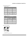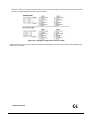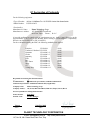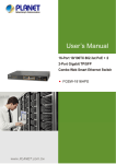
1
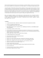
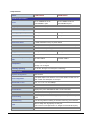
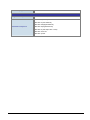
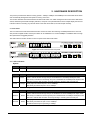
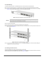
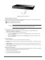
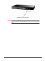
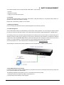
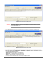
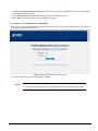
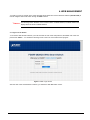
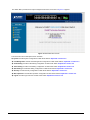
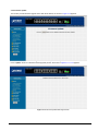
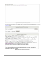
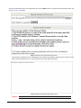
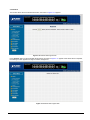
User's Manual FGSW-1820CS FGSW-2620CS 16/24-Port 10/100Mbps with 2 Gigabit TP / SFP Combo Web Smart Switch -1- Trademarks Copyright © PLANET Technology Corp. 2008. Contents subject to revision without prior notice. PLANET is a registered trademark of PLANET Technology Corp. All other trademarks belong to their respective owners. Disclaimer PLANET Technology does not warrant that the hardware will work properly in all environments and applications, and makes no warranty and representation, either implied or expressed, with respect to the quality, performance, merchantability, or fitness for a particular purpose. PLANET has made every effort to ensure that this User’s Manual is accurate; PLANET disclaims liability for any inaccuracies or omissions that may have occurred. Information in this User’s Manual is subject to change without notice and does not represent a commitment on the part of PLANET. PLANET assumes no responsibility for any inaccuracies that may be contained in this User’s Manual. PLANET makes no commitment to update or keep current the information in this User’s Manual, and reserves the right to make improvements to this User’s Manual and/or to the products described in this User’s Manual, at any time without notice. If you find information in this manual that is incorrect, misleading, or incomplete, we would appreciate your comments and suggestions. FCC Warning This equipment has been tested and found to comply with the limits for a Class A digital device, pursuant to Part 15 of the FCC Rules. These limits are designed to provide reasonable protection against harmful interference when the equipment is operated in a commercial environment. This equipment generates, uses, and can radiate radio frequency energy and, if not installed and used in accordance with the Instruction manual, may cause harmful interference to radio communications. Operation of this equipment in a residential area is likely to cause harmful interference in which case the user will be required to correct the interference at his own expense. CE Mark Warning This is a Class A product. In a domestic environment, this product may cause radio interference, in which case the user may be required to take adequate measures. WEEE Warning To avoid the potential effects on the environment and human health as a result of the presence of hazardous substances in electrical and electronic equipment, end users of electrical and electronic equipment should understand the meaning of the crossed-out wheeled bin symbol. Do not dispose of WEEE as unsorted municipal waste and have to collect such WEEE separately. Revision PLANET 16 / 24-Port 10/100Mbps with 2 Gigabit TP / SFP Combo Web Smart Switch User's Manual FOR MODELS: FGSW-1820CS / FGSW-2620CS REVISION: 1.0(FEBRUARY.2008) Part No.: 2080-A81150-000 -2- TABLE OF CONTENTS 1. INTRODUCTION ...................................................................................................................................................... 4 1.1 CHECKLIST................................................................................................................................................................ 4 1.2 ABOUT THE SWITCH .................................................................................................................................................. 4 1.3 FEATURES ................................................................................................................................................................. 5 1.4 SPECIFICATION .......................................................................................................................................................... 6 2. HARDWARE DESCRIPTION.................................................................................................................................. 8 2.1 FRONT PANEL ........................................................................................................................................................... 8 2.2 REAR PANEL ............................................................................................................................................................. 9 2.3 HARDWARE INSTALLATION....................................................................................................................................... 9 3. SWITCH MANAGEMENT..................................................................................................................................... 13 3.1 OVERVIEW .............................................................................................................................................................. 13 3.2 MANAGEMENT METHOD ......................................................................................................................................... 13 3.2.1 Web Management ........................................................................................................................................... 13 3.2.2 PLANET Smart Discovery Utility ................................................................................................................... 13 3.3 LOGGING ON TO THE FGSW-1820CS / FGSW-2620CS ......................................................................................... 15 4. WEB MANAGEMENT ............................................................................................................................................. 16 4.1 LOGIN IN TO THE SWITCH ........................................................................................................................................ 16 4.2 SYSTEM................................................................................................................................................................... 18 4.2.1 System Information ......................................................................................................................................... 19 4.2.2 IP Configuration ............................................................................................................................................. 20 4.2.3 Password Setting............................................................................................................................................. 21 4.2.4 Factory Default............................................................................................................................................... 22 4.2.5 Firmware Update............................................................................................................................................ 23 4.2.6 Reboot ............................................................................................................................................................. 26 4.3 PORT MANAGEMENT ............................................................................................................................................... 27 4.3.1 Port Configuration.......................................................................................................................................... 28 4.3.2 Port Mirroring ................................................................................................................................................ 30 4.3.3 Bandwidth Control.......................................................................................................................................... 31 4.3.4 Broadcast Storm Control ................................................................................................................................ 32 4.3.5 Port Statistics .................................................................................................................................................. 33 4.4 VLAN SETTING ...................................................................................................................................................... 34 4.4.1 Port Based VLAN............................................................................................................................................ 37 4.4.2 Port Based VLAN Setting example: ................................................................................................................ 38 4.4.3 802.1Q VLAN.................................................................................................................................................. 39 4.4.4 802.1Q VLAN Setting example ....................................................................................................................... 42 4.4.5 MTU VLAN ..................................................................................................................................................... 48 4.5 TRUNK .................................................................................................................................................................... 49 4.6 QOS SETTING .......................................................................................................................................................... 51 4.6.1 Priority Mode.................................................................................................................................................. 52 4.6.2 Class of Service Configuration ....................................................................................................................... 53 4.6.3 TCP / UDP Port Based QoS ........................................................................................................................... 55 4.7 SECURITY FILTER .................................................................................................................................................... 57 4.7.1 MAC Address Filter ........................................................................................................................................ 58 4.7.2 TCP / UDP Filter............................................................................................................................................ 59 4.8 MISC OPERATION .................................................................................................................................................... 61 4.9 LOGOUT .................................................................................................................................................................. 62 5. SWITCH OPERATION............................................................................................................................................ 63 5.1 ADDRESS TABLE ..................................................................................................................................................... 63 5.2 LEARNING ............................................................................................................................................................... 63 5.3 FORWARDING & FILTERING .................................................................................................................................... 63 5.4 STORE-AND-FORWARD ........................................................................................................................................... 63 5.5 AUTO-NEGOTIATION............................................................................................................................................... 63 6. TROUBLESHOOTING ............................................................................................................................................ 64 APPENDIX A NETWORKING CONNECTION....................................................................................................... 65 A.1 SWITCH‘S RJ-45 PIN ASSIGNMENTS ....................................................................................................................... 65 A.2 RJ-45 CABLE PIN ASSIGNMENT ............................................................................................................................... 65 -3- 1. INTRODUCTION 1.1 Checklist Check the contents of your package for following parts: z FGSW-1820CS or FGSW-2620CS x1 z Quick Installation Guide x1 z User's manual CD x1 z Power cord x 1 z Rubber feet x 4 z Two rack-mounting brackets with attachment screws x1 If any of these pieces are missing or damaged, please contact your dealer immediately, if possible, retain the carton including the original packing material, and use them against to repack the product in case there is a need to return it to us for repair. In the following section, the term “Web Smart Switch” means the two Switch devices, ie. FGSW-1820CS and FGSW-2620CS; term of “switch” can be any third switches. 1.2 About the Switch The FGSW-1820CS / FGSW-2620CS provide 16/24 10/100Mbps Fast Ethernet ports and two Gigabit Ethernet ports, either TP or SFP per port. The two Gigabit ports either can be 1000Base-T for 10/100/1000Mbps or 1000Base-SX/LX through SFP (Small Factor Pluggable) interfaces. The distance can be extended from 100 meters (TP), 550 meters (Multi-mode fiber), up to above 10/20/30/40/50/70/120 kilometers (Single-mode fiber). The FGSW-1820CS / FGSW-2620CS, equipped with non-blocking 7.2 / 8.8Gbps backplane, greatly simplifies the tasks of upgrading your LAN for catering to increase bandwidth demands. For efficient management, the FGSW-1820CS / FGSW-2620CS 16/24-Port 10/100Mbps + 2 Gigabit TP / SFP Combo Web Smart Switch is equipped with remote Web interface. The FGSW-1820CS / FGSW-2620CS can be programmed for -4- advanced switch management functions such as port configuration, port-based / IEEE 802.1Q / MTU VLAN, port mirroring, port trunk, QoS, bandwidth control, broadcast storm control, MAC address / TCP & UDP filter and IGMP Snooping v1/v2. The FGSW-1820CS / FGSW-2620CS provide port-based / IEEE 802.1Q / MTU VLAN (port based / IEEE 802.1Q VLAN including overlapping). The VLAN groups allowed on the FGSW-1820CS / FGSW-2620CS, will be maximally up to 18/26 for port-based / 32 for IEEE 802.1Q VLAN groups. Also the MTU VLAN divide port 1 to port 16/24 as separate LAN group and only can access the public port 17,18 or port 18 / port 25,26 or port 26. Via supporting port trunking, the FGSW-1820CS / FGSW-2620CS allow the operation of a high-speed trunk combining multiple ports. The FGSW-1820CS / FGSW-2620CS also provide two groups of up to 4-ports for trunking, and it supports fail-over as well. With its Auto-Negotiation capability, all the RJ-45/STP ports of Web Smart Switch can be configured to speeds of 10/20Mbps / 100/200Mbps (Fast Ethernet) and 1000/2000Mbps (Gigabit Ethernet) automatically. In addition, the products are equipped with the MDI/MDI-X auto detection for easily plug and play connection, regardless of cabling types-straight through or crossover. 1.3 Features ◆ Complies with the IEEE 802.3, IEEE 802.3u, IEEE 802.3ab, IEEE 802.3z Gigabit Ethernet standard ◆ 16/24-Port 10/100Mbps Fast Ethernet Switch ◆ 2 10/100/1000Mbps ports share with 2 SFP interfaces ◆ Each Switching ports support auto-negotiation-10/20, 100/200Mbps (Fast Ethernet) , 1000/2000Mbps (Gigabit Ethernet) supported ◆ Auto-MDI/MDI-X detection on each RJ-45 port ◆ Prevents packet loss with back pressure (half-duplex) and IEEE 802.3x PAUSE frame flow control (full-duplex) ◆ High performance Store and Forward architecture, broadcast storm control, runt/CRC filtering eliminates erroneous packets to optimize the network bandwidth ◆ 4K MAC address table, automatic source address learning and ageing ◆ 2.75Mb embedded memory for packet buffers ◆ Remote Web interface for Switch management and setup ◆ Broadcast Storm Control support ◆ Supports up to 18/26 port-based VLAN groups / 32 IEEE 802.1Q VLAN groups / MTU VLAN ◆ Supports up to 2 Trunk groups, each trunk for up to maximum 4 port with 800Mbps bandwidth ◆ Supports QoS , bandwidth control and MAC address filter / TCP & UDP filter on each port ◆ Supports port mirroring function and IGMP Snooping v1 / v2 ◆ Firmware upgrade through Web interface ◆ Password setting, IP setting and device description setting through Planet Smart discovery utility ◆ 19-inch rack mount size ◆ Internal full-range power supply suitable for worldwide use ◆ EMI standards complies with FCC, CE class A -5- 1.4 Specification Model FGSW-1820CS FGSW-2620CS Ports 16 10/ 100Base-TX RJ-45 Auto-MDI/MDI-X ports 24 10/ 100Base-TX RJ-45 Gigabit ports 2 10/100/1000Mbps ports share with 2 SFP interfaces Switch Processing Scheme Store-and-Forward Throughput (packet per second) 5.35Mpps. 6.54Mpps Switch Fabric 7.2Gbps. 8.8Gbps Address Table 4K entries Share Data Buffer 2.75Mb embedded memory for packet buffers Flow Control Back pressure for half duplex, IEEE 802.3x Pause Frame for full duplex Dimensions 440 x 120 x 44 mm (1U height) Weight 1.56 kg Power Requirement 100~240V AC, 50-60 Hz, 0.5A Power Consumption / Dissipation 16 watts / 54BTU Hardware Specification Auto-MDI/MDI-X ports 1.64 kg 19 watts / 64BTU Operating: 0~50 degree C Temperature Storage: -40~70 degree Humidity Operating: 5% to 90%, Storage: 5% to 90% (Non-condensing) Smart function System Configuration Web interface Port configuration Port speed duplex mode selection. Flow control disable / enable. Port disable / enable. Port description on each port Bandwidth Control Yes, 1 / 2 / 4 / 8 / 16 / 32 / 64Mbps Broadcast Storm Control Yes, 5% / 10% / 25% / 50% / Disable Port Statistics Display each port’s detail Ethernet traffic counter information VLAN 18/26 port-based VLAN groups / 32 IEEE 802.1Q VLAN groups / MTU VLAN Port trunking Support 2 groups of 4-Port trunk support, up to 800Mbps bandwidth per trunk Port Mirroring Port mirroring allows monitoring of the traffic across any port in real time QoS MAC address / TCP & UDP filter Allow to assign low / high priority on each port. First-In-First-Out, All-High-before-Low, Weight-Round-Robin QoS policy. Yes -6- IGMP Snooping v1 / v2 Allow to disable or enable. Standards Conformance Regulation Compliance FCC Part 15 Class A, CE IEEE 802.3 (Ethernet) IEEE 802.3u (Fast Ethernet) IEEE 802.3ab(Gigabit Ethernet) Standards Compliance IEEE 802.3z(Gigabit Ethernet) IEEE 802.3x (Full-duplex flow control) IEEE 802.1Q VLAN IEEE 802.1p QoS -7- 2. HARDWARE DESCRIPTION This product provides three different running speeds – 10Mbps, 100Mbps and 1000Mbps in the same Web Smart Switch and automatically distinguishes the speed of incoming connection. This section describes the hardware features of Web Smart Switch. For easier management and control of the Web Smart Switch, familiarize yourself with its display indicators, and ports. Front panel illustrations in this chapter display the unit LED indicators. Before connecting any network device to the Web Smart Switch, read this chapter carefully. 2.1 Front Panel The Front Panel of the Web Smart Ethernet Switch consists of 16/24x Auto-Sensing 10/100Mbps Ethernet RJ-45 Ports, Also provides 2 Gigabit TP/SFP combo ports either can be 1000Base-T for 10/100/1000Mbps or 1000Base-SX/LX through SFP (Small Factor Pluggable) interface. The LED Indicators are also located on the front panel of the Web Smart Switch. Figure 2-1: FGSW-1820CS Switch front panel Figure 2-2: FGSW-2620CS Switch front panel 2.1.1 LED indicators System LED PWR Color Green Function Lights to indicate that the Switch has power. Per 10/100Mbps port LED LNK/ACT Color Green Function Lights to indicate the link through that port is established at 10/100Mbps full duplex mode. Blink slowly to indicate the link through that port is established at 10/100Mbps half duplex mode. Blink fast to indicate that the switch is actively sending or receiving data over that port. 10/100 Orange Steady Lights to indicate the port is run at 100Mbps. Blink Slowly to indicate the port is run at 10Mbps. Per 10/100/1000Base-T port / SFP interfaces LED Color Function Lights to indicate the link through that port is established at 10/100/1000Mbps full duplex mode. LNK/ACT Green Blink slowly to indicate the link through that port is established at 10/100Mbps half duplex mode. Blink fast to indicate that the switch is actively sending or receiving data over that port. Steady Lights to indicate the port is run at 1000Mbps. 100/1000 Green Blink Slowly to indicate the port is run at 100Mbps Off: indicate that the port is operating at 10Mbps. -8- #Notice: 1. Press the RESET button once. The Web Smart Switch will reboot automatically. 2. Press the RESET button for 5 seconds. The Web Smart Switch will back to the factory default mode; the entire configuration will be erased. 2.2 Rear Panel The rear panel of the Web Smart Switch indicates an AC inlet power socket, which accepts input power from 100 to 240VAC, 50-60Hz, 0.5A. Figure 2-3: FGSW-1820C / FGSW-2620CS Switch rear panel Power Notice: 1. The device is a power-required device, it means, it will not work till it is powered. If your networks should active all the time, please consider using UPS (Uninterrupted Power Supply) for your device. It will prevent you from network data loss or network downtime. 2. In some area, installing a surge suppression device may also help to protect your Web Smart Switch from being damaged by unregulated surge or current to the Web Smart Switch. 2.3 Hardware Installation This part describes how to install your Web Smart Switch and make connections to the Switch. Please read the following topics and perform the procedures in the order being presented. To install your Web Smart Switch on a desktop or shelf, simply completed the following steps. 2.3.1 Desktop Installation To install Web Smart Switch on a desktop or shelf, simply completed the following steps: Step 1: Attached the rubber feet to the recessed areas on the bottom of the Web Smart Switch. Step 2: Place the Web Smart Switch on a desktop or shelf near an AC power source. Step 3: Keep enough ventilation space between the Web Smart Switch and the surrounding objects. #Notice: When choosing a location, please keep in mind the environmental restrictions discussed in Chapter 1, Section 4, Specification. Step 4: Connect your Switch to network devices. A. B. Connect one end of a standard network cable to the 10/100 RJ-45 ports on the front of the Web Smart Switch. Connect the other end of the cable to the network devices such as printer servers, workstations or routers…etc. #Notice: Connection to the Web Smart Switch requires UTP Category 5 network cabling with RJ-45 tips. For more information, please see the Cabling Specification in Appendix A. Step 5: Supply power to the Web Smart Switch. A. Connect one end of the power cable to the Web Smart Switch. B. Connect the power plug of the power cable to a standard wall outlet then power on the Web Smart Switch. When the Web Smart Switch receives power, the Power LED should remain solid Green. -9- 2.3.2 Rack Mounting To install the Web Smart Switch in a 19-inch standard rack, follow the instructions described below. Step 1: Place your Web Smart Switch on a hard flat surface, with the front panel positioned towards your front side. Step 2: Attach a rack-mount bracket to each side of the Web Smart Switch with supplied screws attached to the package. Figure 2-4 shows how to attach brackets to one side of the Web Smart Switch. Figure 2-4 Attaching the brackets to the Web Smart Switch Caution: You must use the screws supplied with the mounting brackets. Damage caused to the parts by using incorrect screws would invalidate your warranty. Step 3: Secure the brackets tightly. Step 4: Follow the same steps to attach the second bracket to the opposite side. Step 5: After the brackets are attached to the Web Smart Switch, use suitable screws to securely attach the brackets to the rack, as shown in Figure 2-5. Figure 2-5 Mounting the Web Smart Switch in a Rack Step 6: Precede with the steps 4 and steps 5 of section 2.3.1 Desktop Installation to connect the network cabling and supply power to your Web Smart Switch. 2.3.3 Installing the SFP transceiver The sections describe how to insert an SFP transceiver into an SFP slot. The SFP transceivers are hot-pluggable and hot-swappable. You can plug-in and out the transceiver to/from any SFP port without having to power down the Web Smart Switch. As the Figure 2-6 appears. - 10 - Figure 2-6 Plug-in the SFP transceiver Approved PLANET SFP Transceivers PLANET Web Smart Switch supports both single mode and multi mode SFP transceiver. The following list of approved PLANET SFP transceivers is correct at the time of publication: ■MGB-SX SFP (1000Base-SX SFP transceiver ) ■MGB-LX SFP (1000Base-LX SFP transceiver ) #Notice: It recommends using PLANET SFP transceiver on the Web Smart Switch. If you insert a SFP transceiver that is not supported, the Web Smart Switch will not recognize it. Before connect the other switches, workstation or Media Converter. 1. Make sure both side of the SFP transceiver are with the same media type, for example: 1000Base-SX to 1000Base-SX, 1000Base-LX to 1000Base-LX. 2. Check the fiber-optic cable type match the SFP transceiver model. ¾ To connect to 1000Base-SX SFP transceiver, use the multi-mode fiber cable- with one side must be male duplex LC connector type. ¾ To connect to 1000Base-LX SFP transceiver, use the single-mode fiber cable-with one side must be male duplex LC connector type. Connect the fiber cable 1. Attach the duplex LC connector on the network cable into the SFP transceiver. 2. Connect the other end of the cable to a device – switches with SFP installed, fiber NIC on a workstation or a Media Converter.. 3. Check the LNK/ACT LED of the SFP slot on the front of the Web Smart Switch. Ensure that the SFP transceiver is operating correctly. 4. Check the Link mode of the SFP port if the link failed. Co works with some fiber-NICs or Media Converters, set the Link mode to “1000 Force” is needed. Remove the transceiver module 1. Make sure there is no network activity by consult or check with the network administrator. Or through the management interface of the switch/converter (if available) to disable the port in advance. 2. Remove the Fiber Optic Cable gently. 3. Turn the handle of the MGB module to horizontal. 4. Pull out the module gently through the handle. - 11 - Figure 2-7 Pull out the SFP transceiver #Notice: Never pull out the module without pull the handle or the push bolts on the module. Direct pull out the module with violent could damage the module and SFP module slot of the Web Smart Switch. - 12 - 3. SWITCH MANAGEMENT This chapter describes how to manage the Web Smart Switch. Topics include: - Overview - Management method - Logging on to the Web Smart Switch 3.1 Overview The Web Smart Switch provides a user-friendly, Web interface. Using this interface, you can perform various switch configuration and management activities, including: Please refer to the following Chapter 4 for the details. 3.2 Management Method User can manage the Web Smart Switch by Web Management via a network connection. 3.2.1 Web Management The PLANET FGSW-1820CS / FGSW-2620CS provide a built-in browser interface. You can manage the Switch remotely by having a remote host with Web browser, such as Microsoft Internet Explorer, Netscape Navigator or Mozilla Firefox. The following shows how to startup the Web Management of the Switch, please note the Switch is configured through an Ethernet connection, make sure the manager PC must be set on the same IP subnet address, for example, the default IP address of the Switch is 192.168.0.100 (the factory-default IP address), then the manager PC should be set at 192.168.0.x (where x is a number between 1 and 254, except 100), and the default subnet mask is 255.255.255.0. Use Internet Explorer 5.0 or above Web browser, enter default IP address http://192.168.0.100 After entering the username and password (default user name and password is “admin”) in login screen 3.2.2 PLANET Smart Discovery Utility For easily list the FGSW-1820CS / FGSW-2620CS in your Ethernet environment, the Planet Smart Discovery Utility from user’s manual CD-ROM is an ideal solution. The following install instructions guiding you for run the Planet Smart Discovery Utility. 1. Deposit the Planet Smart Discovery Utility in administrator PC. 2. Run this utility and the following screen appears. - 13 - Figure 3-1 Planet Smart Discovery Utility Screen #Notice: If there are two LAN cards or above in the same administrator PC, choose different LAN card by use the “Select Adapter” tool. 3. Press “Refresh” button for list current connected devices in the discovery list, the screen is shown as follow. Figure 3-2 Planet Smart Discovery Utility Screen 3. This utility show all necessary information from the devices, such as MAC Address, Device Name, firmware version, Device IP Subnet address, also can assign new password, IP Subnet address and description for the devices. 4. After setup completed, press “Update Device”, “Update Multi” or “Update All” button to take affect. The meaning of the 3 buttons above are shown as below: Update Device: use current setting on one single device. Update Multi: use current setting on choose multi-devices. Update All: use current setting on whole devices in the list. The same functions mentioned above also can be finding in “Option” tools bar. - 14 - 5. To click the “Control Packet Force Broadcast” function, it can allow assign new setting value to the Web Smart Switch under different IP subnet address. 6. Press “Connect to Device” button then the Web login screen appears in Figure 3-3. 7. Press “Exit” button to shutdown the planet Smart Discovery Utility. 3.3 Logging on to the FGSW-1820CS / FGSW-2620CS When you log on to the Web Smart Switch Web interface for the first time, a sign-on string appears and you are prompted for a Web login username and password. Figure 3-3 Web Smart Switch Web Login Screen The factory default login username and password is admin. #Notice: 1. 2. For FGSW-1820CS the display will be the same to FGSW-2620CS. For security reason, please change and memorize the new password after this first setup. - 15 - 4. WEB MANAGEMENT To modify your PC’s IP domain to the same with Web Smart Switch then use the default IP address (192.168.0.100) to remote configure Web Smart Switch through the Web interface. #Notice: The following section will base on the console screens of FGSW-2620CS, for FGSW-1820CS the display will be the same to FGSW-2620CS. 4.1 Login in to the Switch To access the Web-browser interface you must first enter the user name and password, the default user name and password is "admin”. You will see the following screen comes out on the Web browser program: Figure 4-1 Web Login Screen After the User name and Password is entered, you will see the Web Main Menu screen. - 16 - The Switch Menu provide seven major management functions, the screen in Figure 4-2 appears. Figure 4-2 Web Main Menu Screen The seven items and it description shown as below: ◆ System: Provide System configuration of Web Smart Switch. Explained in section 4.2. ◆ Port Management: Provide Port Management configuration of Web Smart Switch. Explained in section 4.3. ◆ VLAN Setting: Provide VLAN Setting configuration of Web Smart Switch. Explained in section 4.4. ◆ Trunk Setting: Provide Trunk Setting configuration of Web Smart Switch. Explained in section 4.5. ◆ QoS Setting: Provide QoS Setting configuration of Web Smart Switch. Explained in section 4.6. ◆ Security: Provide Security configuration of Web Smart Switch. Explained in section 4.7. ◆ Misc Operation: Provide Misc Operation configuration of Web Smart Switch. Explained in section 4.8. ◆ Logout: Provide Logout function of Web Smart Switch. Explained in section 4.9. - 17 - 4.2 System This section provides System Information, IP Configuration, Password Setting, Factory Default, Firmware Update and Reboot functions of Web Smart Switch, the screen in Figure 4-3 appears and Table 4-1 describes the System object of Web Smart Switch. Figure 4-3 System Web Page Screen Object Description System Information Display the MAC address, Hardware Version, and Software Version, Device Description. Explained in section 4.2.1. IP Configuration Allow to change the IP subnet address of Web Smart Switch. Explained in section 4.2.2. Password Setting Allow to change the username and password of Web Smart Switch. Explained in section 4.2.3. Factory Default Allow reset the Web Smart Switch to factory default mode. Explained in section 4.2.4. Firmware Update Allow proceed firmware upgrade process of Web Smart Switch. Explained in section 4.2.5. Reboot Allow reboot the Web Smart Switch. Explained in section 4.2.6. Table 4-1 Descriptions of the System Web Page Screen Objects - 18 - 4.2.1 System Information This section displays the MAC address, Hardware Version and Software Version, also allow define the device description and press “Apply” button to take affect. The screen in Figure 4-4 appears. Figure 4-4 System Information Web Page Screen #Notice: Up to 16 characters is allowed for the Device Description. - 19 - 4.2.2 IP Configuration This section provides change the IP Address, Subnet Mask and Gateway, the screen in Figure 4-5 appears. Figure 4-5 IP Configuration Web Page Screen .After setup complete and press “Apply” button to take affect. The following screen in Figure 4-6 appears and then another Web page login screen with new IP address will show up. After input correct username and password then can continue the Web Smart Switch management. Figure 4-6 IP Configuration Web Page Screen - 20 - 4.2.3 Password Setting This section provides change the Username and Password, the screen in Figure 4-7 appears. Figure 4-7 Password Setting Web Page Screen #Notice: Up to 8 characters is allowed for the username and password assign. - 21 - 4.2.4 Factory Default This section provides reset the Web Smart Switch to factory default mode, the screen in Figure 4-8 appears. Figure 4-8 Factory Default Web Page Screen Press “Factory Default” button to take affect. The following screen in Figure 4-9 appears and then another Web page login screen with default setting will show up. After input default username and password then can continue the Web Smart Switch management. Figure 4-9 Factory Default Web Page Screen - 22 - 4.2.5 Firmware Update This section provides firmware upgrade of the Web Smart Switch, the screen in Figure 4-10 appears. Figure 4-10 Firmware Update Web Page Screen Press “Update” button for start the firmware upgrade process, the screen in Figure 4-11 & 4-12 appears. Figure 4-11 Firmware Update Web Page Screen - 23 - Figure 4-12 Firmware Update Web page Screen Then the following screen appears, press “Browser” button to find the firmware location administrator PC, the screen in Figure 4-13 appears. Figure 4-13 Firmware Update Web Page Screen - 24 - After find the firmware location from administrator PC, press “Update” button to start the firmware upgrade process. The screen in Figure 4-14 appears. Figure 4-14 Firmware Update Web Page Screen When firmware upgrade process is completed then the following screen appears, please wait for a while for system reboot. After device reboot then can use the latest firmware of the Web Smart Switch. Figure 4-15 Firmware Update Web Page Screen #Notice: Recommend to use IE 6.0 or FireFox browser tools for firmware upgrade process. - 25 - 4.2.6 Reboot This section allows reboot the Web Smart Switch, the screen in Figure 4-16 appears. Figure 4-16 Reboot Web Page Screen Press “Reboot” button to reboot the Web Smart Switch, the screen in Figure 4-17 appears. After device reboot completed, the Web login screen appears and login for further management. Figure 4-17 Reboot Web Page Screen - 26 - 4.3 Port Management This section provides Port Configuration, Port Mirroring, Bandwidth Control, Broadcast Storm Control and Port Statistics from Web Smart Switch, the screen in Figure 4-18 appears and Table 4-2 describes the system object of Web Smart Switch. Figure 4-18 Port Management Web Page Screen Object Description Port Configuration Allow to configure each port of Web Smart Switch. Explained in section 4.3.1. Port Mirroring Allow to use port mirroring function of Web Smart Switch. Explained in section 4.3.2. Bandwidth Control Allow to configure bandwidth control of each port from Web Smart Switch. Explained in section 4.3.3. Broadcast Storm Control Allow to configure broadcast storm control of each port from Web Smart Switch. Explained in section 4.3.4. Port Statistics Display each port statistics of Web Smart Switch. Explained in section 4.3.5. Table 4-2 Descriptions of the Port Management Web Page Screen Objects - 27 - 4.3.1 Port Configuration This section introduces detail settings of per port on Web Smart Switch; the screen in Figure 4-19 & 4-20 appears and Table 4-3 & 4-4 descriptions the Port Configuration objects of Web Smart Switch. Figure 4-19 Port Configuration Web Page Screen Figure 4-20 Port Configuration Web Page Screen - 28 - Object Port Description Port Description Allow choosing all or one port of Web Smart Switch for further management, the available options is All & 01 to 26 (FGSW-2620CS). Or All & 01 to 18 (FGSW-1820CS). Allow choosing various speed duplex mode from one specific port of Web Smart Switch, the available options are shown as below: Auto Negotiation 1000Full(1000Mbps Port Only) 100Full 100Half 10Full 10Half Default mode is Auto Negotiation. Allow to configure Flow control function of each port from Web Smart Switch, the available options are Enable and Disable. Default mode is Enable. Allow disable or enable one specific port from Web Smart Switch, the available options are Enable and Disable. Default mode is Enable. Allow input per Port Description of Web Smart Switch, up to maximum 8 characters allow. Apply button Press “Apply” button for save current configuration of each port on Web Smart Switch. Speed Mode Flow Control State Table 4-3 Descriptions of the Port Configuration Web Page Screen Objects Object Description Port Indicate port 1 to port 26 (FGSW-2620CS), port 1 to port 18 (FGSW-1820CS). Current Status Display per port Current Status, such as Link, Speed Mode and Flow Control. Link Display current link status from each port of the Web Smart Switch. Speed Mode Display current speed mode from each port of the Web Smart Switch. Flow Control Display current flow control status from each port of the Web Smart Switch. Setting Status Speed Mode Display per port Current Setting Status, such as Speed Mode, Flow Control, State and Port Description. Display per port Speed Mode setting value. Flow Control Display per port Flow Control setting value. State Display per port State setting value. Port Description Display per Port Description. Refresh button Press “Refresh” button to refresh current status. Table 4-4 Descriptions of the Port Configuration Web Page Screen Objects - 29 - 4.3.2 Port Mirroring This section introduces detail settings of Port Mirroring function of Web Smart Switch; the screen in Figure 4-21 appears and Table 4-5 descriptions the Port Mirroring objects of Web Smart Switch. Figure 4-21 Port Mirroring Web Page Screen Object Description Monitored Packets Provide disable and enable the Port Mirroring function, the available options are Disable, RX, TX, TX & RX. Default mode is Disable. Destination Port The destination port can be used to see all monitor port traffic. It can connect destination port to LAN analyzer or Netxray. Source Port The source port that want to monitor. All monitor port traffic will be copied to destination port. Apply button Press this button for save current configuration of Web Smart Switch. Table 4-5 Descriptions of the Port Mirroring Screen Objects - 30 - 4.3.3 Bandwidth Control This section introduces detail settings of Bandwidth Control function of Web Smart Switch; the screen in Figure 4-22 appears and Table 4-6 description the Bandwidth Control objects of Web Smart Switch. Figure 4-22 Bandwidth Control Web Page Screen Object Description Port Indicate port 1 to port 24 (FGSW-2620CS), port 1 to port 16 (FGSW-1820CS) Tx Rate Provide No Limit, 1Mbps, 2Mbps, 4Mbps, 8Mbps, 16Mbps, 32Mbps, 64Mbps different transmit rate for bandwidth control function of Web Smart Switch. Default mode is “No Limit”. Provide No Limit, 1Mbps, 2Mbps, 4Mbps, 8Mbps, 16Mbps, 32Mbps, 64Mbps different receive rate for bandwidth control function of Web Smart Switch. Default mode is “No Limit”. Press this button for save current configuration of each port on Web Smart Switch. Rx Rate Apply button Table 4-6 Descriptions of the Bandwidth Control Screen Objects - 31 - 4.3.4 Broadcast Storm Control This section introduces detail settings of Broadcast Storm Control function of Web Smart Switch; the screen in Figure 4-23 appears and Table 4-7 descriptions the Broadcast Storm Control objects of Web Smart Switch. Figure 4-23 Broadcast Storm Control Web Page Screen Object Description Filter Mode Provide 5%, 10%, 25%, 50%, Disable different filter mode. Default mode is Disable. Apply button Press this button for save current configuration of Web Smart Switch. Table 4-7 Descriptions of the Broadcast Storm Control Screen Objects - 32 - 4.3.5 Port Statistics This section introduces detail information of Port Statistics function of Web Smart Switch; the screen in Figure 4-24 appears and Table 4-8 descriptions the Port Statistics objects of Web Smart Switch. Figure 4-24 Port Statistics Web Page Screen Object Description Counter Mode Provide different type of Ethernet traffic counter mode, the available options are shown as below: Selection Receive Packet & Transmit Packet collision Count & Transmit Packet Drop Packet & Receive Packet CRC error Packet & Receive Packet Default mode is Receive Packet & Transmit Packet. Port Indicate port 1 to port 26 (FGSW-2620CS), port 1 to port 18 (FGSW-1820CS). Transmit Display Transmit count value from each port. Receive Display Receive count value from each port. Refresh button Press this button for refresh the Port Statistics value of Web Smart Switch. Clear button Press this button for clear the Port Statistics value of Web Smart Switch. Table 4-8 Descriptions of the Port Statistics Screen Objects - 33 - 4.4 VLAN Setting A Virtual LAN (VLAN) is a logical network grouping that limits the broadcast domain. It allows you to isolate network traffic so only members of the VLAN receive traffic from the same VLAN members. Basically, creating a VLAN from a switch is logically equivalent of reconnecting a group of network devices to another Layer 2 switch. However, all the network devices are still plug into the same switch physically. The Switch supports IEEE 802.1Q (tagged-based) and Port-Base VLAN setting in web management page. In the default configuration, VLAN support is “No VLAN”. Port-based VLAN Port-based VLAN limit traffic that flows into and out of switch ports. Thus, all devices connected to a port are members of the VLAN(s) the port belongs to, whether there is a single computer directly connected to a switch, or an entire department. On port-based VLAN.NIC do not need to be able to identify 802.1Q tags in packet headers. NIC send and receive normal Ethernet packets. If the packet's destination lies on the same segment, communications take place using normal Ethernet protocols. Even though this is always the case, when the destination for a packet lies on another switch port, VLAN considerations come into play to decide if the packet is dropped by the Switch or delivered. IEEE 802.1Q VLANs IEEE 802.1Q (tagged) VLAN are implemented on the Switch. 802.1Q VLAN require tagging, which enables them to span the entire network (assuming all switches on the network are IEEE 802.1Q-compliant). VLAN allow a network to be segmented in order to reduce the size of broadcast domains. All packets entering a VLAN will only be forwarded to the stations (over IEEE 802.1Q enabled switches) that are members of that VLAN, and this includes broadcast, multicast and unicast packets from unknown sources. VLAN can also provide a level of security to your network. IEEE 802.1Q VLAN will only deliver packets between stations that are members of the VLAN. Any port can be configured as either tagging or untagging. The untagging feature of IEEE 802.1Q VLAN allows VLAN to work with legacy switches that don't recognize VLAN tags in packet headers. The tagging feature allows VLAN to span multiple 802.1Q-compliant switches through a single physical connection and allows Spanning Tree to be enabled on all ports and work normally. Any port can be configured as either tagging or untagging. The untagging feature of IEEE 802.1Q VLAN allows VLAN to work with legacy switches that don’t recognize VLAN tags in packet headers. The tagging feature allows VLAN to span multiple 802.1Q-compliant switches through a single physical connection and allows Spanning Tree to be enabled on all ports and work normally. Some relevant terms: Tag - The act of putting 802.1Q VLAN information into the header of a packet. Untag - The act of stripping 802.1Q VLAN information out of the packet header. 802.1Q VLAN Tags The figure below shows the 802.1Q VLAN tag. There are four additional octets inserted after the source MAC address. Their presence is indicated by a value of 0x8100 in the Ether Type field. When a packet's Ether Type field is equal to 0x8100, the packet carries the IEEE 802.1Q/802.1p tag. The tag is contained in the following two octets and consists of 3 bits of user priority, 1 bit of Canonical Format Identifier (CFI - used for encapsulating Token Ring packets so they can be carried across Ethernet backbones), and 12 bits of VLAN ID (VID). The 3 bits of user priority are used by 802.1p. The VID is the VLAN identifier and is used by the 802.1Q standard. Because the VID is 12 bits long, 4094 unique VLAN can be identified. The tag is inserted into the packet header making the entire packet longer by 4 octets. All of the information originally contained in the packet is retained. - 34 - 802.1Q Tag User Priority 3 bits TPID (Tag Protocol Identifier) Destination Address Source Address 6 bytes 12 bits TCI (Tag Control Information) 2 bytes Ethernet Type VLAN TAG 6 bytes VLAN ID (VID) 1 bits 2 bytes Preamble CFI 4 bytes 2 bytes Data FCS 46-1517 bytes 4 bytes The Ether Type and VLAN ID are inserted after the MAC source address, but before the original Ether Type/Length or Logical Link Control. Because the packet is now a bit longer than it was originally, the Cyclic Redundancy Check (CRC) must be recalculated. Adding an IEEE802.1Q Tag Dest. Addr. Src. Addr. Length/E. type Dest. Addr. Src. Addr. E. type Data Tag Old CRC Length/E. type Original Ethernet Data New CRC New Tagged Packet Priority CFI VLAN ID Port VLAN ID Packets that are tagged (are carrying the 802.1Q VID information) can be transmitted from one 802.1Q compliant network device to another with the VLAN information intact. This allows 802.1Q VLAN to span network devices (and indeed, the entire network – if all network devices are 802.1Q compliant). Every physical port on a switch has a PVID. 802.1Q ports are also assigned a PVID, for use within the switch. If no VLAN are defined on the switch, all ports are then assigned to a default VLAN with a PVID equal to 1. Untagged packets are assigned the PVID of the port on which they were received. Forwarding decisions are based upon this PVID, in so far as VLAN are concerned. Tagged packets are forwarded according to the VID contained within the tag. Tagged packets are also assigned a PVID, but the PVID is not used to make packet forwarding decisions, the VID is. Tag-aware switches must keep a table to relate PVID within the switch to VID on the network. The switch will compare the VID of a packet to be transmitted to the VID of the port that is to transmit the packet. If the two VID are different the switch will drop the packet. Because of the existence of the PVID for untagged packets and the VID for tagged packets, tag-aware and tag-unaware network devices can coexist on the same network. A switch port can have only one PVID, but can have as many VID as the switch has memory in its VLAN table to store them. Because some devices on a network may be tag-unaware, a decision must be made at each port on a tag-aware device before packets are transmitted – should the packet to be transmitted have a tag or not? If the transmitting port is connected to a tag-unaware device, the packet should be untagged. If the transmitting port is connected to a tag-aware device, the packet should be tagged. Default VLANs The Switch initially configures one VLAN, VID = 1, called "default." The factory default setting assigns all ports on the Switch to the "default". As new VLAN are configured in Port-based mode, their respective member ports are removed from the "default." #Notice: Base on the Switch chipset specification, the Switch supports SVL(Shared VLAN Learning) , all VLAN groups share the same Layer 2 learned MAC address table. - 35 - VLAN Settings This section provides VLAN Configuration from Web Smart Switch, the screen in Figure 4-25 appears and Table 4-9 describes the VLAN Configuration object of Web Smart Switch. Figure 4-25 VLAN Setting Web Page Screen Object VLAN Mode Apply button Description Provide different VLAN operation mode, the available options are shown as below: No VLAN Port Based VLAN. Explained in section 4.4.1. 802.1Q VLAN. Explained in section 4.4.3. MTU. Explained in section 4.4.5. Default mode is No VLAN. Press this button for save current configuration of Web Smart Switch. Table 4-9 Descriptions of the VLAN Setting Screen Objects - 36 - 4.4.1 Port Based VLAN This section introduces detail information of Port Based VLAN function of Web Smart Switch; Choose “Port Based VLAN” from VLAN from the VLAN Mode and press “Apply” button to enable the port based VLAN function. The screen in Figure 4-26 & 4-27 & 4-28 appears and Table 4-10 description the Port Based VLAN objects of Web Smart Switch. Figure 4-26 Port Based VLAN Configuration Web Page Screen Figure 4-27 Port Based VLAN Configuration Web Page Screen - 37 - Figure 4-28 Port Based VLAN Configuration Web Page Screen Object Description VID Display different VLAN ID from multi-port based VLAN groups. VLAN Name Port Assign and display different VLAN name from multi-port based VLAN groups. Up to maximum 8 characters allow. Indicate port 1 to port 26 (FGSW-2620CS), port 1 to port 18 (FGSW-1820CS). Member Allow to click specific port as member port from different port based VLAN groups. Apply button Press this button for save current configuration of Web Smart Switch. Delete Group Press this button for delete existence port based VLAN groups. Add New Group Press this button for create a new port based VLAN groups. Up to maximum 18 port based VLAN groups on FGSW-1820CS and 26 port based VLAN groups on FGSW-2620CS. Table 4-10 Descriptions of the VLAN Setting Screen Objects 4.4.2 Port Based VLAN Setting example: VLAN scenario 1. Port 26 is the file server port for all the workstations 2. Port 1 to port 25 is different devices that do not need to see each other Setup steps 1. Port Setting 1.1 Assign VLAN 1 for the first VLAN group with port 1 and port 26. 1.2 Assign VLAN 2 for the second VLAN group with port 2 and port 26 1.3 Repeat the same steps for port 3 to port 25. i.e. 3 & 26, 4 & 26, ….., 25 & 26 - 38 - After the above steps port 1 to port 25 is being separated physically due to it belongs to different VLAN groups (different VLAN). However, they all can access port 26 due to port 26 is using overlapping feature to communicate with port 1 to port 25. 4.4.3 802.1Q VLAN This section introduces detail information of IEEE 802.1Q VLAN function of Web Smart Switch; Choose “802.1Q VLAN” from VLAN from the VLAN Mode and press “Apply” button to enable the 802.1Q VLAN function. The screen in Figure 4-29 & 4-30 & 4-31 appears and Table 4-11 description the 802.1Q VLAN objects of Web Smart Switch. Figure 4-29 802.1Q VLAN Configuration Web Page Screen Figure 4-30 802.1Q VLAN Configuration Web Page Screen - 39 - Figure 4-31 802.1Q VLAN Configuration Web Page Screen Object Description Group Display the existence 802.1Q VLAN groups. VID Display different VLAN ID from multi-802.1Q VLAN groups. VLAN Name Port Assign and display different VLAN name from multi-802.1Q VLAN groups. Up to maximum 8 characters allow. Indicate port 1 to port 26 (FGSW-2620CS), port 1 to port 18 (FGSW-1820CS). Member Allow to click specific port as member port from different 802.1Q VLAN groups. Apply button Press this button for save current configuration of Web Smart Switch. Per Port Setting Allow to define per port UnTag / Tag, Uplink and PVID. The screen in Figure 4-32 appears. Delete Group Press this button for delete existence 802.1Q VLAN groups. Add New Group Press this button for create a new 802.1Q VLAN groups. Up to maximum 32 802.1Q VLAN groups support on Web Smart Switch Table 4-11 Descriptions of the 802.1Q VLAN Setting Screen Objects - 40 - Figure 4-32 802.1Q VLAN Per Port Setting Web Page Screen This section introduces detail information of IEEE 802.1Q VLAN Per Port Setting of Web Smart Switch; The Table 4-12 description the 802.1Q VLAN Per Port Setting objects of Web Smart Switch. Object Description Port Indicate port 1 to port 26 (FGSW-2620CS), port 1 to port 18 (FGSW-1820CS). Link Type Define UnTag or Tag on each port of Web Smart Switch. Default mode is “UnTag”. Uplink Define No Uplink or Uplink on each port of Web Smart Switch. Default mode is “No Uplink”. PVID Assign PVID on each port of Web Smart Switch. Default PVID is “1”. Apply button Press this button for save current configuration of Web Smart Switch. VLAN Group Setting Return to 802.1Q VLAN Group Setting screen. Table 4-12 Descriptions of the 802.1Q VLAN Per Port Setting Screen Objects - 41 - 4.4.4 802.1Q VLAN Setting example Two separate 802.1Q VLAN scenario 1. Shows how the Web Smart Switch handles Untagged and Tagged traffic from two 802.1Q VLAN groups. 2. Each VLAN isolate network traffic, only the same VLAN member port can receive traffic from each other. Figure 4-33 two separate 802.1Q VLAN diagram VLAN Group VID Untagged Members Tagged Members VLAN Group 1 1 Port-7~Port-24 N/A VLAN Group 2 2 Port-1,Port-2 Port-3 VLAN Group 3 3 Port-4,Port-5 Port-6 Table 4-13 VLAN and Port Configuration The scenario described as follow: Untagged packet entering VLAN 2 1. While [PC-1] transmit an untagged packet enters Port-1, the Web Smart Switch will tag it with a VLAN Tag=2. [PC-2] and [PC-3] will received the packet through Port-2 and Port-3. 2. [PC-4], [PC-5] and [PC-6] received no packet. 3. While the packet leaves Port-2, it will be stripped away it tag becoming an untagged packet. 4. While the packet leaves Port-3, it will keep as a tagged packet with VLAN Tag=2. Tagged packet entering VLAN 2 5. While [PC-3] transmit a tagged packet with VLAN Tag=2 enters Port-3, [PC-1] and [PC-2] will received the packet through Port-1 and Port-2. 6. While the packet leaves Port-1 and Port-2, it will be stripped away it tag becoming an untagged packet. Untagged packet entering VLAN 3 7. While [PC-4] transmit an untagged packet enters Port-4, the switch will tag it with a VLAN Tag=3. [PC-5] and [PC-6] will received the packet through Port-5 and Port-6. 8. While the packet leaves Port-5, it will be stripped away it tag becoming an untagged packet. 9. While the packet leaves Port-6, it will keep as a tagged packet with VLAN Tag=3. #Notice: At this example, VLAN Group 1 just set as default VLAN, but only focus on VLAN 2, VLAN 3 traffic flow. - 42 - Setup steps 1. Create VLAN Group: Set VLAN Group 1 = default-VLAN with VID (VLAN ID) =1. Add two VLANs – VLAN 2 and VLAN 3, VLAN Group 2 with VID=2, VLAN Group 3 with VID=3. Figure 4-34 Add new VLAN Group Screen 2. Assign VLAN Member : VLAN 2 : Port-1,Port-2 and Port-3. VLAN 3 : Port-4, Port-5 and Port-6. VLAN 1: All other ports – Port-7~Port-24. Figure 4-35 Assign VLAN members for VLAN 2 and VLAN 3 - 43 - Please remember to remove the Port 1 – Port 6 from VLAN 1 membership, since the Port 1 – Port 6 had been assigned to VLAN 2 and VLAN 3. Figure 4-36 Remove specify ports from VLAN 1 member #Notice: Its import to remove the VLAN member port from VLAN 1 group. Or the ports would become overlapping setting. - 44 - 3. Assign PVID for each port: Port-1,Port-2 and Port-3 : PVID=2. Port-4,Port-5 and Port-6 : PVID=3. Port-7~Port-24 : PVID=1. 4. Enable VLAN Tag for specific ports Link Type: Port-3 (VLAN-2) and Port-6 (VLAN-3). The Per Port VLAN configuration in Figure 4-37 appears. Figure 4-37 Port 1-Port 6 802.1Q VLAN Configuration Two separate 802.1Q VLAN with overlapping area scenario 1. Based on the two separate VLAN group examples above, VLAN 2 and VLAN 3 member port cannot see each other. 2. The member ports from VLAN 2 and VLAN 3 need to access one public server. Figure 4-38 A Server connect to the VLAN overlapping area 1. Specify Port-7 on the Web Smart Switch that connects to the server. - 45 - 2. Assign Port-7 to both VLAN 2 and VLAN 3 at the VLAN Member configuration page. The screen in Figure 4-39 appears. Figure 4-39 VLAN overlap port setting 3. Define a VLAN 1 as a “Public Area” that overlapping with both VLAN 2 members and VLAN 3 members. Figure 4-40 VLAN 1 – The public area member assign - 46 - 4. Setup Port-7 with “PVID=1” at VLAN Per Port Configuration page. The screen in Figure 4-41 appears. Figure 4-41 Setup Port-7 with PVID-1 Although the VLAN 2 members: Port-1 to Port-3 and VLAN 3 members: Port-4 to Port-6 also belongs to VLAN 1. But with different PVID settings, packets form VLAN 2 or VLAN 3 is not able to access to the other VLAN. - 47 - 4.4.5 MTU VLAN This section introduces detail information of MTU VLAN function of Web Smart Switch; Choose “MTU” from VLAN from the VLAN Mode and press “Apply” button to enable the MTU VLAN function. The screen in Figure 4-42 appears and Table 4-14 description the MTU VLAN objects of Web Smart Switch. Figure 4-42 MTU VLAN Configuration Web Page Screen Object Description MTU Port Indicate the MTU Port of Web Smart Switch. Member Port Indicate the Member Port of Web Smart Switch. Apply button Press this button for save current configuration of Web Smart Switch. Table 4-14 Descriptions of the MTU VLAN Setting Screen Objects - 48 - 4.5 Trunk Port link aggregations can be used to increase the bandwidth of a network connection or to ensure fault recovery. Link aggregation lets you group up to 4 consecutive ports into a single dedicated connection between any two the Switch or other Layer 2 switches. However, before making any physical connections between devices, use the Link aggregation Configuration menu to specify the link aggregation on the devices at both ends. When using a port link aggregation, note that: 。 The ports used in a link aggregation must all be of the same media type (RJ-45, 100 Mbps fiber). 。 The ports that can be assigned to the same link aggregation have certain other restrictions (see below). 。 Ports can only be assigned to one link aggregation. 。 The ports at both ends of a connection must be configured as link aggregation ports. 。 None of the ports in a link aggregation can be configured as a mirror source port or a mirror target port. 。 Enable the link aggregation prior to connecting any cable between the switches to avoid creating a data loop. 。 Disconnect all link aggregation port cables or disable the link aggregation ports before removing a port link aggregation to avoid creating a data loop. It allows a maximum of 4 ports to be aggregated at the same time and up to 2 groups. If the group is defined as a local static link aggregation group, then the number of ports must be the same as the group member ports. - 49 - Trunk Setting This function allows to configuring the trunk function. It provides up to two trunk groups and each trunk group provides 4 member ports. Also provide four various Trunk Hash Algorithm policies for selection. The screen in Figure 4-43 appears and Table 4-15 description the Trunk Setting objects of Web Smart Switch. Figure 4-43 Trunk Setting Web Page Screen Object Description Trunk Hash Algorithm Provide four various Trunk Hash Algorithm polices, the available options are shown as below: selection SA & DA(Default) Port ID SA DA Default mode is SA & DA. Trunk1 Indicate the Trunk Member Port 1,2,3,4 of Web Smart Switch. Trunk2 Indicate the Trunk Member Port 5,6,7,8 of Web Smart Switch. Apply Press this button for save current configuration of Web Smart Switch. Table 4-15 Descriptions of the Trunk Setting Screen Objects - 50 - 4.6 QoS Setting This function provides QoS Setting of Web Smart Switch; the screen in Figure 4-44 appears and Table 4-16 descriptions the QoS Setting of Web Smart Switch. Figure 4-44 QoS Setting Web Page Screen Object Priority Mode Description Provide three different Priority polices on Web Smart Switch. Explained in section 4.6.1. Class of Service Con- Provide three different polices on each port of Web Smart Switch. Explained in section 4.6.2. figuration TCP/UDP Port Based Allow to define various QoS mode on TCP / UDP port. Explained in section 4.6.3. QoS Table 4-16 Descriptions of the QoS Setting Screen Objects - 51 - 4.6.1 Priority Mode This section introduces detail information of Priority Mode of Web Smart Switch; the screen in Figure 4-45 appears and Table 4-17 descriptions the Priority Mode of Web Smart Switch. Figure 4-45 Priority Mode Web Page Screen Object Priority Mode Apply Description Provide three different Priority polices on Web Smart Switch, the available options are shown as below: Fist-In-First-Out All-High-Before-Low Weight-Round-Robin= Low weight (0-7 range) : High weight (0-7 range) Default mode is First-In-First-Out. Press this button for save current configuration of Web Smart Switch. Table 4-17 Descriptions of the Priority Mode Screen Objects - 52 - 4.6.2 Class of Service Configuration This section introduces detail information of Class of Service Configuration of Web Smart Switch; the screen in Figure 4-46 appears and Table 4-18 descriptions the Class of Service Configuration of Web Smart Switch. Figure 4-46 Class of Service Configuration Web Page Screen Object Description Enable High Priority Allow to disable or enable the High Priority function. Default mode is Enable. Port Indicate port 1 to port 26 (FGSW-2620CS), port 1 to port 18 (FGSW-1820CS). Port Base Define per port Class of Service policy based on Port Base policy. VLAN Tag Define per port Class of Service policy based on VLAN Tag priority policy. IP /DS Define per port Class of Service policy based on IP / DS policy. Apply Press this button for save current configuration of Web Smart Switch. Table 4-18 Descriptions of the Class of Service Configuration Screen Objects VLAN Priority tag value define IEEE 802.1p priority value from VLAN tag High Priority User priority values= 4~7 Low Priority User priority values= 0~3 - 53 - IP TOS/DSCP Priority value define TOS/DSCP Value High Priority Low Priority EF AF11 AF21 AF31 AF41 DSCP 46 DSCP 10 DSCP 18 DSCP 26 DSCP 34 (101110) (001010) (010010) (011010) (100010) Other DSCP values DSCP: Differentiated Services Code Point EF: Expected Forwarding AF: Assured Forwarding - 54 - 4.6.3 TCP / UDP Port Based QoS This section introduces detail information of TCP / UDP Port Based QoS Configuration of Web Smart Switch; the screen in Figure 4-47 & 4-48 appears and Table 4-19 descriptions the TCP / UDP Port Based QoS Configuration of Web Smart Switch. Figure 4-47 TCP / UDP Port Based QoS Configuration Web Page Screen Figure 4-48 TCP / UDP Port Based QoS Configuration Web Page Screen - 55 - Object Description Protocol Display different Protocol for define the QoS policy in option FTP(20,21) Provide F-I-F-O, Discard, Low, High options. SSH(22) Provide F-I-F-O, Discard, Low, High options. TELNET(23) Provide F-I-F-O, Discard, Low, High options. SMTP(25) Provide F-I-F-O, Discard, Low, High options. DNS(53) Provide F-I-F-O, Discard, Low, High options. TFTP(69) Provide Low, High options. HTTP(80,8080) Provide Low, High options. POP3(110) Provide F-I-F-O, Discard, Low, High options. NEWS(119) Provide F-I-F-O, Discard, Low, High options. SNTP(123) Provide F-I-F-O, Discard, Low, High options. NetBIOS(137~139) Provide F-I-F-O, Discard, Low, High options. IMAP(143,220) Provide F-I-F-O, Discard, Low, High options. SNMP(161,162) Provide F-I-F-O, Discard, Low, High options. HTTPS(443) Provide F-I-F-O, Discard, Low, High options. MSN(1863) Provide F-I-F-O, Discard, Low, High options. XRD_RDP(3389) Provide F-I-F-O, Discard, Low, High options. QQ(4000,8000) Provide F-I-F-O, Discard, Low, High options. ICQ(5190) Provide F-I-F-O, Discard, Low, High options. Yahoo(5050) Provide F-I-F-O, Discard, Low, High options. BOOTP_DHCP(67,68) Provide Low, High options. User_Define_a Provide F-I-F-O, Discard, Low, High options. User_Define_b Provide F-I-F-O, Discard, Low, High options. User_Define_c Provide F-I-F-O, Discard, Low, High options. User_Define_d Provide F-I-F-O, Discard, Low, High options. User_Define Port number (1~65535) Mask(0~255) Disable Allow to define 4 protocol port numbers, such as Port and Mask. The available options are shown as below: User_Define_a User_Define_b User_Define_c User_Define_d Allow to choose “Disable” or “Enable” options. Default mode is Disable. Not Override Allow to choose “Override” or “Not Override” options. Default mode is Not Override . Apply Press this button for save current configuration of Web Smart Switch. Table 4-19 Descriptions of the TCP / UDP Port Based QoS Configuration Screen Objects - 56 - 4.7 Security Filter This function provides Security Filter of Web Smart Switch; the screen in Figure 4-49 appears and Table 4-20 descriptions the Security Filter of Web Smart Switch. Figure 4-49 Security Filter Web Page Screen Object Description MAC Address Filter Allow define three MAC Address on per port of Web Smart Switch. Explained in section 4.7.1. TCP/UDP Filter Allow define the filter policy of TCP / UDP flow on Web Smart Switch. Explained in section 4.7.2. Table 4-20 Descriptions of the Security Filter Web Page Screen Objects - 57 - 4.7.1 MAC Address Filter This section introduces detail information of MAC Address Filter of Web Smart Switch; the screen in Figure 4-50 appears and Table 4-21 & 4-22 descriptions the MAC Address Filter of Web Smart Switch. Figure 4-50 MAC Address Filter Web Page Screen Object Description MAC Address Allow to input three MAC Address on per port of Web Smart Switch. Select Port Allow to select port 1 to port 26 (FGSW-2620CS) or port 1 to port 18 (FGSW-1820CS). Binding Allow to Disable or Enable the binding function on each port of Web Smart Switch. Apply Press this button for save current configuration of Web Smart Switch. Table 4-21 Descriptions of the MAC Address Filter Screen Objects Object Description Port Indicate port 1 to port 26 (FGSW-2620CS), port 1 to port 18 (FGSW-1820CS). Binding Status Display Binding Status from each port of Web Smart Switch. MAC 1 Display first assigns MAC Address on each port of Web Smart Switch. MAC 2 Display second assigns MAC Address on each port of Web Smart Switch. MAC 3 Display third assigns MAC Address on each port of Web Smart Switch. Table 4-22 Descriptions of the MAC Address Filter Screen Objects - 58 - 4.7.2 TCP / UDP Filter This section introduces detail information of TCP / UDP Filter of Web Smart Switch; the screen in Figure 4-51 & 4-52 appears and Table 4-23 descriptions the TCP / UDP Filter Configuration of Web Smart Switch. Figure 4-51 TCP / UDP Filter Web Page Screen Figure 4-52 TCP / UDP Filter Web Page Screen - 59 - Object Description Function Enable Allow to Disable or Enable the TCP / UDP Filter function. Default mode is Disable. Port Filtering Rule Allow to Forward or Block the Port Filtering Rule. Default mode is Block. Protocol Display different Protocol for define the TCP / UDP Filter policy. FTP(20,21) SSH(22) TELNET(23) SMTP(25) DNS(53) TFTP(69) HTTP(80,8080) POP3(110) NEWS(119) SNTP(123) NetBIOS(137~139) Allow to choose list protocol for filtering IMAP(143,220) SNMP(161,162) HTTPS(443) MSN(1863) XRD_RDP(3389) QQ(4000,8000) ICQ(5190) Yahoo(5050) BOOTP_DHCP(67,68) User_Define_a User_Define_b User_Define_c User_Define_d Secure Egress Port Apply Indicate port 1 to port 26 (FGSW-2620CS), port 1 to port 18 (FGSW-1820CS). Click specific port for filtering. Press this button for save current configuration of Web Smart Switch. Table 4-23 Descriptions of the TCP / UDP Filter Configuration Screen Objects - 60 - 4.8 Misc Operation This function provides Misc Operation of Web Smart Switch; the screen in Figure 4-53 appears and Table 4-24 descriptions the Misc Operation of Web Smart Switch. Figure 4-53 Misc Operation Web Page Screen Object Description Output Queue Aging Time VLAN Striding IGMP Snooping V1 & V2 Apply Allow define the Output Queue Aging Time of Web Smart Switch, the available options are Disable, 200ms, 400ms, 600ms and 800ms. Default mode is Disable. Allow Disable or Enable the VLAN Striding function of Web Smart Switch. Default mode is Disable. Allow Disable or Enable the IGMP Snooping V1 & V2 function of Web Smart Switch. Default mode is Disable. Press this button for save current configuration of Web Smart Switch. Table 4-24 Descriptions of the Misc Operation Web Page Screen Objects - 61 - 4.9 Logout This section provide Web logout function on Web Smart Switch, after choose this function and the following screen appears in Figure 4-54 & 4-55. Please press “Logout” button to take effect and Login Web Screen appears. Please re-login the Web Smart Switch for further management. Figure 4-54 Logout Web Page Screen Figure 4-55 Login Web Page Screen - 62 - 5. SWITCH OPERATION 5.1 Address Table The Switch is implemented with an address table. This address table composed of many entries. Each entry is used to store the address information of some node in network, including MAC address, port no, etc. This information comes from the learning process of Ethernet Switch. 5.2 Learning When one packet comes in from any port. The Switch will record the source address, port no. And the other related information in address table. This information will be used to decide either forwarding or filtering for future packets. 5.3 Forwarding & Filtering When one packet comes from some port of the Ethernet Switching, it will also check the destination address besides the source address learning. The Ethernet Switching will lookup the address-table for the destination address. If not found, this packet will be forwarded to all the other ports except the port which this packet comes in. And these ports will transmit this packet to the network it connected. If found, and the destination address is located at different port from this packet comes in, the Ethernet Switching will forward this packet to the port where this destination address is located according to the information from address table. But, if the destination address is located at the same port with this packet comes in, then this packet will be filtered. Thereby increasing the network throughput and availability. 5.4 Store-and-Forward Store-and-Forward is one type of packet-forwarding techniques. A Store-and Forward Ethernet Switching stores the incoming frame in an internal buffer, do the complete error checking before transmission. Therefore, no error packets occurrence, it is the best choice when a network needs efficiency and stability. The Ethernet Switch scans the destination address from the packet-header, searches the routing table provided for the incoming port and forwards the packet, only if required. The fast forwarding makes the switch attractive for connecting servers directly to the network, thereby increasing throughput and availability. However, the switch is most commonly used to segment existing hubs, which nearly always improves overall performance. An Ethernet Switching can be easily configured in any Ethernet network environment to significantly boost bandwidth using conventional cabling and adapters. Due to the learning function of the Ethernet switching, the source address and corresponding port number of each incoming and outgoing packet are stored in a routing table. This information is subsequently used to filter packets whose destination address is on the same segment as the source address. This confines network traffic to its respective domain, reducing the overall load on the network. The Switch performs "Store and forward" therefore, no error packets occur. More reliably, it reduces the re-transmission rate. No packet loss will occur. 5.5 Auto-Negotiation The STP ports on the Switch have built-in "Auto-negotiation". This technology automatically sets the best possible bandwidth when a connection is established with another network device (usually at Power On or Reset). This is done by detect the modes and speeds at the second of both device is connected and capable of, both 10Base-T and 100Base-TX devices can connect with the port in either Half- or Full-Duplex mode. 1000Base-T can be only connected in Full-duplex mode. - 63 - 6. TROUBLESHOOTING This chapter contains information to help you solve problems. If the Switch is not functioning properly, make sure the Ethernet Switch was set up according to instructions in this manual. The Link LED is not lit Solution: Check the cable connection and remove duplex mode of the Switch. Some stations cannot talk to other stations located on the other port Solution: Please check the VLAN, port trunking function that may introduce this kind of problem. Performance is bad Solution: Check the full duplex status of the Ethernet Switch. If the Ethernet Switch is set to full duplex and the partner is set to half duplex, then the performance will be poor. 100Base-TX port link LED is lit, but the traffic is irregular Solution: Check that the attached device is not set to dedicate full duplex. Some devices use a physical or software switch to change duplex modes. Auto-negotiation may not recognize this type of full-duplex setting. Why the Switch doesn’t connect to the network Solution: Check the LNK/ACT LED on the switch Try another port on the Switch Make sure the cable is installed properly Make sure the cable is the right type Turn off the power. After a while, turn on power again. How to deal forgotten password situation of FGSW-1820CS / FGSW-2620CS? Solution: Please press Reset button at front panel for 5 seconds then the Web Smart Switch will reset to factory default mode(username and password: admin) - 64 - APPENDIX A NETWORKING CONNECTION A.1 Switch‘s RJ-45 Pin Assignments 1000Mbps, 1000Base T RJ-45 Connector pin assignment Contact MDI MDI-X 1 BI_DA+ BI_DB+ 2 BI_DA- BI_DB- 3 BI_DB+ BI_DA+ 4 BI_DC+ BI_DD+ 5 BI_DC- BI_DD- 6 BI_DB- BI_DA- 7 BI_DD+ BI_DC+ 8 BI_DD- BI_DC- 10/100Mbps, 10/100Base-TX RJ-45 Connector pin assignment MDI MDI-X Contact Media Dependant Interface Media Dependant Interface -Cross 1 Tx + (transmit) Rx + (receive) 2 Tx - (transmit) Rx - (receive) 3 Rx + (receive) Tx + (transmit) 4, 5 Not used 6 Rx - (receive) 7, 8 Tx - (transmit) Not used A.2 RJ-45 cable pin assignment 6 32 1 6 321 6 3 21 The standard RJ-45 receptacle/connector - 65 - There are 8 wires on a standard UTP/STP cable and each wire is color-coded. The following shows the pin allocation and color of straight cable and crossover cable connection: Figure A-1: Straight-Through and Crossover Cable Please make sure your connected cables are with same pin assignment and color as above picture before deploying the cables into your network. 2080-A81150-000 - 66 - EC Declaration of Conformity For the following equipment: *Type of Product: *Model Number: 16-Port 10/100Base-TX + 2G TP/SFP Combo Web Smart Switch FGSW-1820CS * Produced by: Manufacturer‘s Name : Manufacturer‘s Address: Planet Technology Corp. 11F, No 96, Min Chuan Road Hsin Tien, Taipei, Taiwan , R. O.C. is herewith confirmed to comply with the requirements set out in the Council Directive on the Approximation of the Laws of the Member States relating to Electromagnetic Compatibility Directive on (89/336/EEC,92/31/EEC,93/68/EEC). For the evaluation regarding the EMC, the following standards were applied: Emission Conducted / Radiated Harmonic Flicker Immunity ESD RS EFT/ Burst Surge CS Voltage Disp EN 50081-1 EN 55022 EN 61000-3-2 EN 61000-3-3 EN 55024 EN 61000-4-2 EN 61000-4-3 EN 61000-4-4 EN 61000-4-5 EN 61000-4-6 EN 61000-4-11 (1992) (1998) (1995) (1995) (1998) (1995) (1996) (1995) (1995) (1996) (1994) Responsible for marking this declaration if the: ⌧ Manufacturer Authorized representative established within the EU Authorized representative established within the EU (if applicable): Company Name: Planet Technology Corp. Company Address: 11F, No.96, Min Chuan Road, Hsin Tien, Taipei, Taiwan, R.O.C Person responsible for making this declaration Name, Surname Kent Kang Position / Title : Product Manager Taiwan Place 22th Feb, 2008 Date Legal Signature PLANET TECHNOLOGY CORPORATION e-mail: [email protected] 11F, No. 96, Min Chuan Road, Hsin Tien, Taip http://www.planet.com.tw EC Declaration of Conformity For the following equipment: *Type of Product: *Model Number: 24-Port 10/100Base-TX + 2G TP/SFP Combo Web Smart Switch FGSW-2620CS * Produced by: Manufacturer‘s Name : Manufacturer‘s Address: Planet Technology Corp. 11F, No 96, Min Chuan Road Hsin Tien, Taipei, Taiwan , R. O.C. is herewith confirmed to comply with the requirements set out in the Council Directive on the Approximation of the Laws of the Member States relating to Electromagnetic Compatibility Directive on (89/336/EEC). For the evaluation regarding the EMC, the following standards were applied: Emission Harmonic EN 55022 EN 61000-3-2 Flicker Immunity ESD RS EFT/ Burst Surge CS Magnetic Field Voltage Disp EN 61000-3-3 EN 55024 IEC 61000-4-2 IEC 61000-4-3 IEC 61000-4-4 IEC 61000-4-5 IEC 61000-4-6 IEC 61000-4-8 IEC 61000-4-11 (1998 + 2000 Class A) (1995 + A1:1998 + A2:1998 + A14:2000) (1995 + A1:2001) (1998 + A1:2001 + A2:2003) (1995 + A1:1998 + A2:2001) (1995 + A1:1998 + A2:2001) (1995 + A1:2001 + A2:2001) (1995 + A1:2001) (1996 + A1:2001) (1993 + A1:2001) (1994 + A1:2001) Responsible for marking this declaration if the: ⌧ Manufacturer Authorized representative established within the EU Authorized representative established within the EU (if applicable): Company Name: Planet Technology Corp. Company Address: 11F, No.96, Min Chuan Road, Hsin Tien, Taipei, Taiwan, R.O.C Person responsible for making this declaration Name, Surname Kent Kang Position / Title : Product Manager Taiwan Place 22th Feb, 2008 Date Legal Signature PLANET TECHNOLOGY CORPORATION e-mail: [email protected] http://www.planet.com.tw 11F, No. 96, Min Chuan Road, Hsin Tien, Taipei, Taiwan, R.O.C. Tel:886-2-2219-9518 Fax:886-2-2219-9528