1
Serial WAN Router
ERT-805
User’s Manual
Trademarks
Copyright PLANET Technology Corp. 2004.
Contents subject to revision without prior notice.
PLANET is a registered trademark of PLANET Technology Corp.
to their respective owners.
All other trademarks belong
Disclaimer
PLANET Technology does not warrant that the hardware will work properly in all environments
and applications, and makes no warranty and representation, either implied or expressed, with
respect to the quality, performance, merchantability, or fitness for a particular purpose.
PLANET has made every effort to ensure that this User’s Manual is accurate; PLANET
disclaims liability for any inaccuracies or omissions that may have occurred.
Information in this User’s Manual is subject to change without notice and does not represent a
commitment on the part of PLANET. PLANET assumes no responsibility for any inaccuracies
that may be contained in this User’s Manual. PLANET makes no commitment to update or keep
current the information in this User’s Manual, and reserves the right to make improvements to
this User’s Manual and/or to the products described in this User’s Manual, at any time without
notice.
If you find information in this manual that is incorrect, misleading, or incomplete, we would
appreciate your comments and suggestions.
FCC Warning
his equipment has been tested and found to comply with the limits for a Class A digital device,
pursuant to Part 15 of the FCC Rules. These limits are designed to provide reasonable
protection against harmful interference when the equipment is operated in a commercial
environment. This equipment generates, uses, and can radiate radio frequency energy and, if
not installed and used in accordance with the Instruction manual, may cause harmful
interference to radio communications. Operation of this equipment in a residential area is likely
to cause harmful interference in which case the user will be required to correct the interference
at his own expense.
CE Mark Warning
This is a Class A product. In a domestic environment, this product may cause radio interference,
in which case the user may be required to take adequate measures.
Revision
PLANET Enterprise Serial Router User's Manual
FOR MODELS: ERT-805
Part No.: EM-ERT805
2
TABLE OF CONTENTS
Chapter 1 Introduction ............................................................................................................ 1
1.1 CHECKLIST ......................................................................................................................... 1
1.2 ABOUT ERT-805................................................................................................................ 1
1.3 PRODUCT FEATURE ............................................................................................................ 2
1.4 PRODUCT SPECIFICATION ................................................................................................... 2
Chapter 2 HARDWARE INSTALLATION ................................................................................. 4
2.1 PACKAGE CONTENTS .......................................................................................................... 4
2.2 ERT-805 OUTLOOK ............................................................................................................ 4
2.3 INSTALLATION REQUIREMENTS & PHYSICAL INSTALLATION .................................................... 6
2.3.1 Device placement ...................................................................................................... 6
2.3.2 Connect to a Ethernet device .................................................................................... 6
2.3.3 Connect to a Serial Device ........................................................................................ 6
2.3.4 Power on the device .................................................................................................. 7
Chapter 3 Command Line Interface ....................................................................................... 8
3.1 HELP COMMAND ................................................................................................................. 8
3.2 REDISPLAY PREVIOUS COMMAND ........................................................................................ 9
3.3 VERIFY CURRENT CONFIGURATION...................................................................................... 9
3.4 CTRL-Z, CTRL-C AND EXIT ................................................................................................ 10
3.5 LOGIN FROM CONSOLE PORT ............................................................................................ 10
3.6 VIRTUAL TERMINAL ACCESS .............................................................................................. 10
3.7 PASSWORD ENCRYPTION .................................................................................................. 12
Chapter 4 Router Communication Protocol........................................................................ 14
4.1 RIP- ROUTER INFORMATION PROTOCOL ............................................................................ 14
4.1.1 Routing loops........................................................................................................... 14
4.1.1.5 RIP Command ...................................................................................................... 15
4.2 EIGRP – ENHANCED INTERIOR GATEWAY ROUTING PROTOCOL ......................................... 17
4.2.1 EIRGP Command .................................................................................................... 17
4.3 OSPF- OPEN SHORTEST PATH FIRST ............................................................................... 19
4.3.1 OSPF Command ..................................................................................................... 20
4.4 PPP ................................................................................................................................ 22
4.5 HDLC PROTOCOL ............................................................................................................ 28
4.6 SNA ................................................................................................................................ 30
4.6.1 Introduction .............................................................................................................. 30
3
4.7 X.25 PROTOCOL .............................................................................................................. 33
4.8 FRAME RELAY PROTOCOL................................................................................................. 37
Chapter 5 Security ................................................................................................................. 41
5.1 ACCESS-LIST .................................................................................................................... 41
5.2 NAT – NETWORK ADDRESS TRANSLATION ........................................................................ 44
5.3 VPN - IPSEC ................................................................................................................... 47
5.4 FIREWALL- CONTEXT-BASED ACCESS CONTROL (CBAC)................................................... 63
5.5 RADIUS SECURITY (AAA).................................................................................................. 68
Chapter 6 QOS ....................................................................................................................... 74
6.1 CAR – COMMITTED ACCESS RATE.................................................................................... 74
6.2 POLICY-BASED ROUTING ................................................................................................... 77
6.3 CLASS-MAP AND POLICY-MAP ............................................................................................ 78
6.4 QUEUE ............................................................................................................................. 82
6.4.1 FIFO- First IN First Out ............................................................................................ 83
6.4.2 WFQ – Weighted Fair Queuing ............................................................................... 83
6.4.3 Priority Queuing ....................................................................................................... 84
6.4.4 Custom Queuing...................................................................................................... 87
Appendix A Upgrade firmware.............................................................................................. 92
Appendix B Router Dialing ................................................................................................... 94
Appendix C Cables / Pin-assignment for ERT-805 ............................................................. 96
C.1 V.35 DTE – CB-ERTV35-MT ......................................................................................... 96
C.2 V.35 DCE – CB-ERTV35-FC ......................................................................................... 96
C.3 V.24 DTE – CB-ERT232-MT ......................................................................................... 97
C.4 V.24 DCE – CB-ERT232-FC ......................................................................................... 98
C.5 X.21 DTE – CB-ERTX21-MT ......................................................................................... 98
C.6 X.21 DCE – CB-ERTX21-FC ......................................................................................... 99
C.7 RJ-45 CONSOLE CABLE ................................................................................................. 100
C.8 DB9 TO RJ45................................................................................................................ 100
4
Chapter 1 Introduction
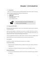
1.1 Checklist
Thank you for purchasing Planet’s ERT-805 Enterprise Serial Router. Before continuing,
please check the contents of your package for following parts:
Ø
ERT-805 Serial WAN Router
Ø
Power Cord
Ø
DB9 adapter
Ø
RJ-45 to RJ-45 modem cable
Ø
User’s Manual CD
Ø
Quick installation Guide
if any of these pieces are missing or damage please
contact your dialer immediately.
1.2 About ERT-805
ERT-805 provides single WAN port, which is T1/E1 serial interface, single LAN port, and single
console (Async) port.
With IPSec/VPN capability, the ERT-805 not only being a standard router but also can be a
router with feature-enhanced security. ERT-805 is supports MD5-HMAC/SHA1-HMAC and
certificate authentication, DES-CBC and 3DES-CBC encryption.
The other capabilities that ERT-805 provides are NAT, Access-list, AAA security, CBAC firewall
and QOS. With these functions ERT-805 is efficiency and secure network device.
User interface
ERT-805 is only able to use command line interface (CLI) to configure.
Protocol and routing
Ø
ERT-805 supports few WAN protocols on its WAN port: PPP, HDLC, SDLC, frame-relay,
LAPB and X.25.
Ø
Support static and dynamic routing protocol: static route, RIP, EIGRP and OSPF
Network Management
Ø
Connect PC to ERT-805 through network and run Telnet to manage it through command
line interface
1
Ø
ERT-805 supports SNMP and can be managed by using SNMP management software
1.3 Product Feature
Ø
Support PPP, FR, X.25, HDLC, LAPB, SDLC, SLIP and Stun
Ø
Complies with IEEE802.3 10Base-T, IEEE 802.3u 100Base-TX Standard
Ø
One serial WAN port, one RJ-45 10/100Mbps LAN port and one Console port
Ø
Provide RIP, EIGRP, OSPF and Static routing protocol
Ø
Provide Access-list, AAA, RADIUS, PAP, CHAP and CBAC for network security
Ø
Network Address Translator (NAT) simultaneous use of one IP address
Ø
Provide IPSec (DES/3DES), IKE and GRE for VPN
Ø
DHCP Serve with dynamic IP assignment for LAN port
Ø
Provide QOS to increase network efficiency
Ø
Provide WFQ, priority queuing and custom queuing to increase network performance
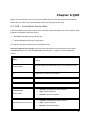
1.4 Product Specification
Model
ERT-805
Device Specification
LAN
1 x 10/100Base-TX (RJ-45)
WAN
1 x Serial Port (DB-25)
Console
1 x RJ-45
LED
5; Power, LAN Speed, LAN Link/Activity, WAN and Console Link/Activity
Network standard
IEEE802.3, 10Base-T, IEEE802.3u, 100Base-TX
Router OS Operation
Communication
PPP, frame-relay, X.25, PPPOE. HDLC, SDLC, SLIP and LAPB
Security
ACL, NAT, AAA RADIUS, PAP, CHAP and CBAC
Route protocol
RIP V1 and V2, CDP, OSPF, EIGRP and Static
VPN
IPSEC and IKE, GRE
Queue/QOS
WFQ, CQ, priority queuing and rate-limit. Class-map and policy-map
Application
DHCP server, PING, Trace Route, telnet, TFTP
Management
Telnet, Console
Throughput
2Mbps
Environment / Hardware Specification
2
Power Input
100 ~ 240V AC (+/-10%); 50/60Hz (+/-3%) auto-sensing
Power Consumption 10 watts / 34BTU
Dimensions
217 x 135 x 43 mm (1U height)
Weight
1 Kg
Temperature
0 to 50 degree C (operating)
-20 to 70 degree C (storage)
Humidity
10 ~ 90% RH (non-condensing)
Regulatory
FCC, CE class A
3
Chapter 2 HARDWARE INSTALLATION
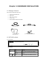
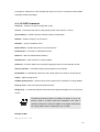
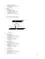
2.1 Package Contents
Item includes with ERT-805 serial router.
Ø
ERT-805 Serial WAN Router
Ø
Power Cord
Ø
DB9 to RJ-45 changer
Ø
Console cable
Ø
Quick Installation Guide and CD-ROM
Console
Cablecable
Light blue
console
Black power cord
DB-9-to-RJ-45 adapter
(for use with
blue Cable)
console cable)
(forlight
Console
CD-ROM user’s Guide &
Quick Install Guide
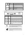
2.2 ERT-805 outlook
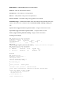
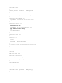
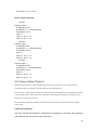
2.2.1 Front Panel
Ent er pr i se W AN Rout er
PWR
LAN
SYNC ASYN C
LNK
ACT
ERT-805
100
LED definition
LEDs
PWR
(Power)
LAN
100
State
Indication
Green
Power on when 100~240VAC power attached
Lights Off
No power
Green
This indicator light for Fast Ethernet connection
4
LNK/
Green blink
This indicator light blink when packets is transmit
ACT
Green
This indicator light green when port is connected
This indicator light green when port is connect with
Green
serial port
Serial
Blink
This indicator light blink when packets is transmit
Green blink
Configuration process
Lights Off
Not in configuration
Console
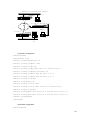
Rear Panel
100~240V AC
Console
Serial
Sync.
Async.
Printing
Ports Type Description
Console
RJ-45
Fast Ethernet
LAN
50/60HZ
Asynchronies port of ERT-805. Allows the connection to a
terminal device or PC for management or asynchronize dialing.
Synchronies port of ERT-805. Allows the connection with a
Serial
DB-25
Synchronize/ Asynchronize device like CSU/DSU modem
Fast Ethernet interface of ERT-805. Allows to connect to a
Fast Ethernet
RJ-45
Ethernet hub/switch through Category 3 or above UTP cable.
The power socket of ERT-805. The allowed power input is
Power
100~240VAC
range from 100VAC to 240VAC (+/-10%), 50/60Hz (+/-3%),
socket
auto-sensing
M
Warning!
The two RJ-45 ports of ERT-805 are not a telephone port.
Connect to a telephone wire or PSTN line to the ports may
cause the router permanently malfunction.
Serial cable is not bundled together with the router, please
consult your local dealer for the available serial cable for your
CSU/DSU modem.
5
2.3 Installation requirements & Physical Installation
To install the ERT-805 serial router, the following is required:
Ø
An Ethernet device, hub or switch with a free MDI-X RJ-45 interface
Ø
One Category 3, 4, 5, EIA568A straight UTP cable within 100 meters
Ø
The asynchronous modem or CSU/DSU (Channel Service Unit/Data Service Unit) that is
planned to connect the router
Ø
A serial cable that used to connect the router and the CSU/DSU
Ø
Rack mount accessories, such as rack ears, screws, and screws driver
Ø
A standalone PC or terminal device with a free COM interface
The serial cable and rack ears do not ship with the router,
pleas consult your local dealer for the information.
To install ERT-805 serial router, just following the steps:
Ø
Device placement
Ø
Connect a Ethernet device
Ø
Connect a Serial device
Ø
Connect the power supply
Ø
Connect a terminal or PC for management
2.3.1 Device placement
The ERT-805 is a 1-U height, 10-inch rack-mountable device that can fit to 10-inch cabinet or
19-inch cabinet. Please consult with your local dealer for the available rack ear if you would to
install the router into a 10-inch/19-inch shelf.
You can also place the ERT-805 on the desktop, please install the router in a clean, dry
environment. Avoid install the router in a place with moisture and water around/near-by.
2.3.2 Connect to a Ethernet device
The ERT-805 is with one Fast Ethernet MDI (media dependent Interface) port. This RJ-45
interface an direct connect to any Ethernet or Fast Ethernet hub or switch with MDI-X port
through Category 3 or above, 2-pair straight UTP cable. The maximum distance for the cable
should below 100 meters.
Connect to an Ethernet device with MDI interface, a cross-over cable is required.
2.3.3 Connect to a Serial Device
The ERT-805 is with one synchronize interface that can connect with CSU/DSU with up to E1
line rate.
6
Available connection is as tables below:
WAN Option
RS-232
X.21
V.24
V.35
WAN Encapsulation
Link control (HDLC) or ppp
Frame-relay
X.25
2.3.4 Power on the device
ERT-805 accepts power input from 100 to 240VAC, 50/60Hz power source. Before connect the
power cable to the router, please be sure the AC power output from your power outlet. The
router must connected to earth ground during normal use.
ERT-805 is a power-required device, it means, ERT-805 will not
work until it is powered. If your network and the router will need to
transmit data all the time, please consider use an UPS
(Uninterrupted Power Supply) for your router and the connected
Ethernet Devices. It will prevent you from network data loss.
In some area, installing a surge suppression device may also help
to protect your router from being damaged by unregulated surge or
current to the Switch or the power adapter
7
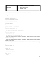
Chapter 3 Command Line Interface
This chapter describes the basic commands to access the router through console interface or
telnet. Be noted if you want to login to ERT-805 through the telnet, then enable password
must be configure.
The user can input system command configuring system protocol by command line port. When
you first login a new router by terminal, the system will give a prompt router>. Now you are in
user mode. After typing the command “enable”, the prompt will change to router#, and now you
are in privilege mode so that you could input more commands including some privilege
command. To enter the global configuration mode, you should type the command “configure
terminal” or “config T”. Then the prompt will change to router(config)#, and you could input
global configuration commands configuring the parameter of the router. If you type the
command “interface serial 0/0” or “int s0/0”,you will notice that the prompt change to
router(config-serial0/0)# and then you are in port configuration。
Prompt
Mode
Router>
Normal User mode
Router#
Enable mode for privilege operation
Rouer(config)#
Configuration mode
Rotuer(config-serial0/0)
Configuration mode of object control
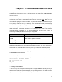
Table for different configure mode
In different configuration mode, the system will give different prompt, and every configuration
mode has its due commands collect. From the prompt you could know what configuration
mode you are in. The left most word of the prompt is the name of the router, from which you
can know that which router you are configuring. You can set the hostname of the router with
the hostname command as below:
router# config terminal
Enter configuration commands, one per line. End with CNTL/Z.
router(config)# hostname ERT_805
ERT_805(config)# exit
ERT_805#
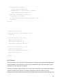
3.1 Help command
“?” and “Tab” keys are two help keys that help user to configure ERT-805. By using a “?” key in
different operate mode, the system will display the help message that tell user what command
they can use in different operate mode. For example:
8
ERT_805> ?
disable
enable
exit
help
logout
pad
ping
ppp
schedule
show
telnet
traceroute
tty
ERT_805>
Turn off privileged commands, enter GUEST user mode
Turn on privileged commands
Exit from the EXEC
Description of the interactive help system
Exit from the EXEC
Open a X.29 PAD connection
Send echo messages
Start IETF Point-to-Point Protocol (PPP)
Schedule one task
Show running system information
Open a telnet connection
Trace route to destination
Print current tty information
“Tab” is another help key, when user typing a word if from the letters you’ve typed the system
could identify the word you want to type, press the tab key then, the system will complete the
word for you automatically.
3.2 Redisplay Previous command
The system saves the inputted commands in a history table, so that you could input the
command again by it. Just simply press↑key and↓key or ctrl + P or Ctrl + N.
You could verify the commands in the history table by the command show history
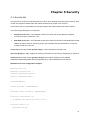
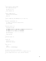
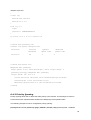
3.3 Verify Current Configuration
The system offered two special hotkeys Ctrl-Q and Ctrl-O with which you could verify your
configuration any time. In privilege mode, global configuration mode or port configuration
mode, the system will display the current configuration right now if you press Ctrl-Q as if you’ve
pressed show run. It means that you needn’t go back to privilege mode to verify your
configuration. The hotkey Ctrl-O is available only in port configuration mode. At anywhere even
when typing a command, if you press the hotkey Ctrl-O, the system will show you the
configuration message of the current port, and then you could go on with your command. This
hotkey avoids the condition that when need verifying the configuration message you have to
quit and enter the port configuration mode again and again. When configuring the routing
protocol you could use the hotkey Ctrl-O as well.
ERT_805(config-serial0/0)#
% CONFIGURATION OF CURRENT OPERATING OBJECT
interface serial 0/0
encapsulation ppp
ip address 10.0.0.1 255.255.255.192
crypto map dynmap
9
clockrate 48000
!
ERT_805(config-serial0/0)#
3.4 Ctrl-Z, Ctrl-C and exit
To exit from the configuration mode directly to privilege mode, you should type Ctrl-Z or Ctrl-C
or type exit. Ctrl-C can be available in other occasions .For example it can stop the current
operation that hasn’t been accomplished.
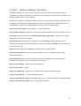
3.5 Login from Console port
Once the terminal has connected to the device, power on the device, the terminal will display
that it is running POST (Power on self-test) procedures.
Then, screen as below will show up. The ERT-805 will prompt with “>”. This means ERT-805 is
in operating mode now.
Types “enable” to enter privilege mode. The ERT-805 will prompt with “#” for privilege mode.
By default there is no password.
Router Software Version 4.2c on Hex_1f73
(3805a)
User Access Verification
Password:
ERT_805> enable
Password:
ERT_805#
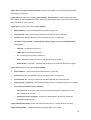
3.6 Virtual Terminal Access
The router allows being accessed from network by telnet, therefore you could configure and
maintain the router by network. Please to note, if the router hasn’t set a password for entering
privilege mode, the router will forbid the network users from entering privilege mode.
ERT805> enable
% Password is not set, you are not allowed to enter privileged mode.
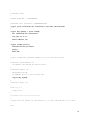
Before login ERT-805 by telnet you must set the password by command “enable password” in
global configuration mode. After that router will allow you’re entering the privilege mode by
10
telnet. If configures like below, the system will only ask for password when anyone access. For
example set the password as “1234”.
ERT805> enable
ERT805# config t
ERT805(config)# enable password 1234
ERT805(config)#line vty 0 4
ERT805(config-line)# login
ERT805(config-line)# password cisco
ERT805(config-line)# exi
ERT805(config)# exit
ERT805#
The password is set by the command “password” in vty and has no concern with what have
been configured above by the command username. The following example shows the result
that configure on above.
Router Software Version 4.2c on Hex_1f73
(3805a)
User Access Verification
Password:
ERT_805> enable
Password:
ERT_805#
The other method is force the network user to verify his username and password. For example
ERT805# config t
Enter configuration commands, one per line. End with CNTL/Z.
ERT805(config)# username rr password cisco
ERT805(config)# line vty 0 5
ERT805(config-line)# login local
ERT805(config-line)# exit
ERT805(config)# exit
ERT805#
The following example shows the result that configure on above:
11
Router Software Version 4.2c on Hex_1f73
(3805a)
User Access Verification
Username: rr
Password: (type the password cisco)
ERT805>
3.7 Password Encryption
Security is a most important issue for all the company in the world because all the system is
require password to protect important information from hacker, such as username, enable
password…etc. In default the system will display these password by clear. So the password is
not very secure. The ERT-805 is offers a command that make the system display the
password by cryptograph. For example:
ERT_805# show run
Building configuration ...
description fault
service password-encryption
service timestamps debug
!
hostname ERT_805
!
enable password 7 3EDRIxtqRWCA
!
username router password 7 65WeJR6evnrR3mP
crypto ipsec transform-set transform-1 esp-3des esp-md5-hmac
!
crypto map dynmap 1 ipsec-isakmp
set transform-set transform-1
set peer 10.0.0.2
match address 100
!
crypto isakmp policy 1
authentication pre-share
group 1
hash md5
!
12
crypto isakmp key 12345678 address 10.0.0.2 255.255.255.192
!
interface fastethernet 0/0
ip address 192.168.99.64 255.255.255.0
!
interface serial 0/0
encapsulation ppp
ip address 10.0.0.1 255.255.255.192
crypto map dynmap
clockrate 48000
!
interface async 0/0
!
line vty 0 5
login
password 7 wAVcXxom8sGSOA
!
ip route 0.0.0.0 0.0.0.0 10.0.0.2
!
access-list 100 permit ip 192.168.99.0 0.0.0.255 192.168.98.0 0.0.0.255
!
end
ERT_805#
13
Chapter 4 Router Communication
Protocol
4.1 RIP- Router Information Protocol
The routing information Protocol (RIP) is a distance-vector protocol that used to exchange
routing information between routers. RIP uses broadcast User Datagram Protocol (UDP) data
packets to exchange routing information and rip is based on distance-vector algorithm. This
routing protocol is determines the best path through an Internet by looking at the number of
hops between the two end nodes. The maximum hops count for RIP is 15 hops.
4.1.1 Routing loops
There is problem with distance-vector routing protocol, which is router cannot acquaint with the
whole status of network. Routers have to get network reachable information depending on
neighboring routers and RIP also comes up against slow convergence, which will introduce
inconsistence. The following methods that used by RIP to decrease possibility of routing loop:
spilt horizon, spilt horizon with poison reverse, Holddown timer and triggered update.
4.1.1.1 Spilt Horizon
The spilt horizon is a technique for preventing reverse routes between two routers. The rule of
spilt horizon is that router never advertised the cost of a destination to neighbor if it is the
current next-hop for the destination.
4.1.1.2 Spilt Horizon with Poison Reverse
The rule for “split horizon” is when sending updates out a particular interface, designate any
networks that were learned from updates received on that interface as unreachable. This
mean is when an interface is up; the router records from which interface a route comes, and
not sends the route back to this interface.
4.1.1.3 Holddown timer
Holddown timer is able to prevent a router from receiving new routing information that was just
removed from routing table. The default holddown timer is 180 seconds.
4.1.1.4 Triggered update
Split horizon with poisoned reverse will break any loop of two routers. However, it is still
possible for loops of three or more routers, to occur. This loop will break only when infinity
(presented as 16) will be reached. Triggered updates are an attempt to speed up this
14
convergence. Whenever a router changes the metric of a route, it is required to send update
messages almost immediately
4.1.1.5 RIP Command
router rip – enable rip in global configuration mode
version - To specify a RIP version used globally by the router (version 1 and 2)
auto-summary – enable automatic network number summarization.
Network – Enable routing on an IP network
Neighbor – specify a neighbor router
Bind-interface – Enable RIP protocol on some interface
Default-metric – set metric of redistributed routes
Distance – define an administrative distance
Distribute-list – Filter networks in routing updates
Offset-list –To add an offset to incoming and outgoing metrics to routes learned via RIP
Passive-interface - To disable sending routing updates on an interface.
Redistribute - To redistribute routes from one routing domain into another routing domain.
Timers – adjust routing timers
Validate-update-source - Perform sanity checks against source address of routing updates
Show ip route – show all routes learned through RIP
Debug ip rip - To show RIP operation information and update messages sent or received by
routers.
The difference between RIPV1 and RIPV2 is RIPV2 is not a new
protocol; rather it is RIPV1 with some extensions. The most of
important extensions in RIPV2 is addition of a Subnet mask field to
the routing update entries, enabling the use of VLSM.
Example of RIP
ERT_805# show run
15
Building configuration ...
description fault
service password-encryption
service timestamps debug
!
hostname ERT_805
!
enable password 7 3EDRIxtqRWCA
!
username router password 7 65WeJR6evnrR3mP
crypto ipsec transform-set transform-1 esp-3des esp-md5-hmac
!
crypto map dynmap 1 ipsec-isakmp
set transform-set transform-1
set peer 10.0.0.2
match address 100
!
crypto isakmp policy 1
authentication pre-share
group 1
hash md5
!
crypto isakmp key 12345678 address 10.0.0.2 255.255.255.192
!
interface fastethernet 0/0
ip address 192.168.99.64 255.255.255.0
!
interface serial 0/0
encapsulation ppp
ip address 10.0.0.1 255.255.255.192
ip ospf network point-to-point
crypto map dynmap
clockrate 48000
!
interface async 0/0
!
router rip
version 2
16
network 10.0.0.0
network 192.168.99.0
!
line vty 0 5
login
password 7 wAVcXxom8sGSOA
!
ip route 0.0.0.0 0.0.0.0 10.0.0.2
!
access-list 100 permit ip 192.168.99.0 0.0.0.255 192.168.98.0 0.0.0.255
!
end
ERT_805#
ERT_805# show ip route
Codes: A--all O--ospf S--static R--rip C--connected E--egp T--tunnel
o--cdp D--EIGRP
[Distance/Metric] g<Group#>
S
0.0.0.0/0 [2/0] via 10.0.0.2 serial0/0* act
C
10.0.0.0/26 [0/1] via 10.0.0.1 serial0/0* act
C
10.0.0.2/32 [1/0] via 10.0.0.1 serial0/0* act
R
192.168.98.0/24 [120/1] via 10.0.0.2 ttl=160, serial0/0* act
C
192.168.99.0/24 [0/1] via 192.168.99.64 fastethernet0/0* act
ERT_805#
4.2 EIGRP – Enhanced interior Gateway Routing Protocol
EIGRP is distance-vector protocol that combines the advantage of distance-vector and link
state protocol. The different between these two protocols is distance-vector protocol shares
everything it knows with directly connected neighbor only. Link state protocols announce
information with directly connected links but share the information with all routers in same area.
Because EIGRP is distance-vector therefore it’s run of the Bellman Ford protocol. These
protocols are prone to routing loops and counting to infinity. As result they must implement
loop-avoidance such as split horizon, route poisoning and holddown timers.
4.2.1 EIRGP Command
router eigrp autonomous system number– enable eigrp in global configuration mode.
Network – enable routing on an IP network
Neighbor – Specify a neighbor router
Auto-summary – Enable automatic network number summarization
17
Bind-interface – enable EIGRP protocol on some interface
Distance – define an administrative distance
Distribute-list – filter networks in routing updates
Metric/e – modify EIREP routing metrics and parameters
Passive-interface - To disable sending routing updates on an interface.
Redistribute eigrp – redistribute information from other routing protocol and there are some
optional value allow user to configure which is bandwidth, delay, reliability, loading and
mtu.
Ip hello-interval eigrp autonomous system number– configure EIGRP hello interval
Ip hold-time eigrp autonomous system number – configure EIGRP hold time
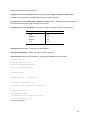
Show ip eigrp interface [detail/AS number] – display interface information.
Following is the example:
ERT_805# show ip eigrp interface
IP-EIGRP neighbors for process 1
Interface
Peers
bandwidth
delay
state
fastethernet0/0
0
10000
1000
1
serial0/0
1
1544
20000
1
ERT_805#
Show ip eigrp neighbor [detail/AS number] – display information of neighbor
ERT_805# show ip eigrp neighbors
IP-EIGRP neighbors for process 1
H
Address
Interface
Hold
Uptime Seq
(sec)
(Num)
0
10.0.0.2
serial0/0
20
00:45:10
4
RT_805#
ERT_805# show run
Building configuration ...
description fault
service password-encryption
service timestamps debug
!
hostname ERT_805
!
enable password 7 3EDRIxtqRWCA
!
username router password 7 65WeJR6evnrR3mP
crypto ipsec transform-set transform-1 esp-3des esp-md5-hmac
!
crypto map dynmap 1 ipsec-isakmp
set transform-set transform-1
set peer 10.0.0.2
match address 100
!
crypto isakmp policy 1
18
authentication pre-share
group 1
hash md5
!
crypto isakmp key 12345678 address 10.0.0.2 255.255.255.192
!
interface fastethernet 0/0
ip address 192.168.99.64 255.255.255.0
!
interface serial 0/0
encapsulation ppp
ip address 10.0.0.1 255.255.255.192
crypto map dynmap
ip hold-time eigrp 1 20
clockrate 48000
!
interface async 0/0
!
router eigrp 1
network 192.168.99.0
network 10.0.0.0
!
line vty 0 5
login
password 7 wAVcXxom8sGSOA
!
ip route 0.0.0.0 0.0.0.0 10.0.0.2
!
access-list 100 permit ip 192.168.99.0 0.0.0.255 192.168.98.0 0.0.0.255
!
end
ERT_805#
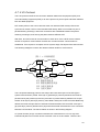
4.3 OSPF- Open Shortest Path First
OSPF is a link state protocol and it uses Dijkstra’s Shortest Path First algorithm to run on the
link state database. This technology is opposed to a distance-vector technology. OSPF router
protocol is interior gateway router protocol that used to make decision on routes in
Autonomous system. The link state protocol is use a cost metric to determine the best path to
a destination.
When router or network’s topology start to change the routing protocol will generate a LSA and
flood it to notify the area or network that belongs.
Types of area
Standard area – This area can accept intra-area, inter-area and external router. This area also
can be backbone area.
Backbone area – the backbone (transit) area always labeled area 0. Backbone area is a
central entity that contains all other area. The backbone is responsible for distributing routing
19
information between non-backbone areas
Stub area – this area do not accept router that belong to external autonomous system (AS).
The routers in stub area use a default route to reach outside autonomous system.
Totally stubby area – This area that does not accept routes from other intra-area and default
routes to be propagated within the area. If the router needs to send a packet to outside of area,
it sends it using a default route.
Not-so-stubby-area – this area allows limited number of external routes that imports into
area.
Types of routers
Internal router – routers that directly connected to the networks belong to the same area.
Backbone router – The router that connect with other Autonomous system bye physical or
victual link.
Area border router (ABR) – A router that attached to multiple areas. ABR routers maintain the
separate database for each area that connects with. Then ABR condense the topological
information for their attached area and distribute to the backbone area.
Autonomous System Boundary router (ASBR) – This router have at least one interface
connect to another autonomous system.
Types of OSPF Network Topologies
Point-to-point – Two routers that directly connect each other by serial interface.
Broadcast multiaccess – Network that connects more then two routers together with
broadcast capability. Such as Ethernet is a broadcast multiaccess.
Nonbroadcast multiaccess (NBMA) – Network support many routers but having no
broadcast capability.
4.3.1 OSPF Command
router ospf <ospf ID> - enable OSPF in global configuration mode.
Network area - address wildcard-mask area area-id
Neighbor [poll-interval | priority] - Specify a neighbor router. For point-to-Multipoint and
NBMA networks, neighbor must be configured. Poll-interval is for ospf dead-router polling
interval. Priority is for ospf priority of non-broadcast neighbor.
Area – OSPF area parameters
20
area area-id authentification -specifying the authentification type is single authentification
area area-id authentification message-digest -specifying the authentification type is
Cryptographic authentication*/
area area-id stub [no-summary] - specifying the area is stub area*/ /* no-summary
emphasizes the only default summary LSA produced into the area
area area-id default-cost cost- For stub area, default summary LSA cost’s value
area area-id nssa -specifying the area is NSSA area
area area-id range address mask [ advertise | not-advertise ] - configuring the area
parameter of range which used to condense the network topology information */
distance admin-distance
redistribute [ connected | rip | static ]
ip ospf network [ broadcast | non-broadcast | point-to-point | point-to-Multipoint ]
ip ospf cost cost - default value is 1
ip ospf retransmit-interval -seconds default value is 5 seconds
ip ospf transmit-delay secondsip ospf priority number-
default value is 1 seconds
It is valid only for Broadcast and NBMA networks
ip ospf hello-interval -seconds
ip ospf dead-interval -seconds
ip ospf authentification-key key -key’s max length is 8 Bytes, it is valid when area’s
authentification type is single authentification
ip ospf message-digest-key keyid md5 key - key’s max length is 16 Bytes, it is valid when
area’s authentification type is Cryptographic authentication
Configuration Example
Router Software Version 4220lab-RT805 on ERT805
(4.2c )
User Access Verification
Password:
ERT-805> enable
21
Password:
ERT_805# show run
Building configuration ...
service password-encryption
service timestamps debug
!
hostname router
!
enable password level 15 7 aNTUS0QSfz8T
!
interface fastethernet 0/0
ip address 192.168.99.64 255.255.255.0
!
interface serial 0/0
encapsulation hdlc
ip address 10.0.0.1 255.255.255.192
ip ospf priority 255
clockrate 48000
!
interface async 0/0
!
router ospf 2
network 192.168.99.0 0.0.0.255 area 0
network 10.0.0.0 0.0.0.255 area 0
!
line vty 0 4
login
password 7 hd3cpRj4s14LeA
!
ip route 0.0.0.0 0.0.0.0 10.0.0.2
!
end
ERT_805#
4.4 PPP
PPP (point-to-point) has provides a standard method for transport multi-protocol over ppp.
PPP is comprise of three main functional components, which is:
22
Ø
PPP has a method for encapsulating multi-protocol datagrams
Ø
Link Control Protocol (LCP) establishes, configures, authenticates and testing the
data-link connection.
Ø
Network Control Protocol (NCP) establish and configure different network-layer protocol.
PPP provides two authentications which is:
Ø
Password Authentication protocol (PAP)
Ø
Challenge Handshake Authentication protocol (CHAP)
PPP authentication using PAP
PAP is using two-way handshake to establish its identity. After PPP link establishment is
complete, the authenticator repeatedly sends username and password until the authentication
is acknowledged or the connection is terminated.
PAP is not an authentication protocol because password is sends cross the link by clear text
and it’s not protection from playback.
PPP authentication using CHAP
CHAP is using three way handshakes to establish it identify. After the PPP link is
establishment is complete, the server sends challenge to the remote node. The remote note
responds with a value calculated by using a one-way hash function (typically MD5). The server
checks the response against its own calculation of expected hash value. If the values match,
the authentication is acknowledged. CHAP is more secured then PAP because it is supports
protection against playback attack through the use of a variable challenge value that is unique
and unpredictable. The use of repeated challenges is intended to limit the time of exposure to
any single attack. The access server is in control of the frequency and timing of the challenges.
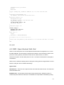
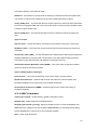
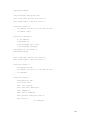
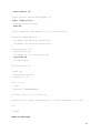
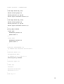
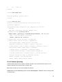
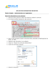
The following is showing a typical PPP session.
23
Figure 4-2 Networking diagram of PAP and CHAP
authentication example
ROUTER A
ROUTER B
encapsulation ppp – encapsulation style to ppp style (interface command)
ppp authentication [pap | chap - enable the PAP or CHAP authentication
username username password password [callback-dialstring]– add the username and
password of the peer into the local user. Callback-dialstring is for callback command in global
command
ppp compress [predictor | stacker] – configure predictor or stacker compress on the
interface
ip tcp header-compress – configure tcp header compress on the interface.
ppp callback [accept | initiate] – configure callback on interface accept is configured in
server and initiate is configured in client
Configuration Example
CHAP example
router# show run
Building configuration ...
service password-encryption
service timestamps debug
!
24
hostname router
!
enable password level 15 7 aNTUS0QSfz8T
!
username ERT-805 password 7 SBFV4NgG60tV
!
interface fastethernet 0/0
ip address 192.168.99.64 255.255.255.0
!
interface serial 0/0
encapsulation ppp
ip address 10.0.0.1 255.255.255.192
ppp authentication chap
clockrate 48000
!
interface async 0/0
!
line vty 0 4
login
password 7 hd3cpRj4s14LeA
!
ip route 192.168.98.0 255.255.255.0 10.0.0.2
!
end
router#
ERT-805# show run
Building configurati
service password-encryption
service timestamps debug
!
hostname ERT-805
!
enable password 7 5EVbxkwzBvfT
!
username router password 7 XNDVyI32Zyje
!
interface fastethernet 0/0
25
ip address 192.168.98.63 255.255.255.0
!
interface serial 0/0
encapsulation ppp
ip address 10.0.0.2 255.255.255.192
ppp authentication chap
!
interface async 0/0
!
line vty 0 4
login
password 7 o2EUq2a6AFiY4D
!
ip route 192.168.99.0 255.255.255.0 10.0.0.1
!
end
PAP example
outer# show run
Building configuration ...
service password-encryption
service timestamps debug
!
hostname router
!
enable password level 15 7 aNTUS0QSfz8T
!
interface fastethernet 0/0
ip address 192.168.99.64 255.255.255.0
!
interface serial 0/0
encapsulation ppp
ip address 10.0.0.1 255.255.255.192
ppp authentication pap
ppp pap sent-username router password 7 wRHOiZagh-kM
ppp compress predictor
ip tcp hearder-compression
!
26
interface async 0/0
!
line vty 0 4
login
password 7 hd3cpRj4s14LeA
!
ip route 192.168.98.0 255.255.255.0 10.0.0.2
!
end
router#
ERT-805# show run
Building configuration ...
service password-encryption
service timestamps debug
!
hostname ERT-805
enable password 7 5EVbxkwzBvfT
!
username router password 7 qBjbURagjK0L
!
interface fastethernet 0/0
ip address 192.168.98.63 255.255.255.0
!
interface serial 0/0
encapsulation ppp
ip address 10.0.0.2 255.255.255.192
ppp authentication pap
ip tcp header-compression
clockrate 48000
!
interface async 0/0
!
line vty 0 4
login
password 7 o2EUq2a6AFiY4D
27
!
ip route 192.168.99.0 255.255.255.0 10.0.0.1
!
end
ERT-805#
4.5 HDLC Protocol
Only when the interface operates in the synchronous mode, can it be encapsulated with
HDLC.
encapsulation hdlc – encapsulation with hdlc type
router# show run
Building configuration ...
service password-encryption
service timestamps debug
!
hostname router
!
enable password level 15 7 aNTUS0QSfz8T
!
username ERT-805 password 7 3hlZiJYY6pOn
!
interface fastethernet 0/0
ip address 192.168.99.64 255.255.255.0
!
interface serial 0/0
encapsulation hdlc
ip address 10.0.0.1 255.255.255.192
!
interface async 0/0
!
line vty 0 4
login
password 7 hd3cpRj4s14LeA
!
ip route 192.168.98.0 255.255.255.0 10.0.0.2
!
28
end
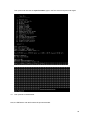
router#
router# debug hdlc s0/0
router#
03:59.544 %serial0/0 Hdlc Port debug turn on
04:01.399 serial0/0 HDLC O(len=162):CDP
01 b4 cc 27 00 01 00 0a 72 6f
75 74 65
04:01.399
72 00 02 00 11 00 00 00 01 01 01 cc 00 04 0a 00 00...
04:03.094 serial0/0 HDLC I(len=22):lmi peer_seq=155,local's=159
04:03.753 %HDLC serial0/0 Keepalive
04:03.753 serial0/0 HDLC O(len=22):lmi local_seq=160,peer's=155
04:13.093 serial0/0 HDLC I(len=22):lmi peer_seq=156,local's=160
04:13.753 %HDLC serial0/0 Keepalive
04:13.753 serial0/0 HDLC O(len=22):lmi local_seq=161,peer's=156
04:23.093 serial0/0 HDLC I(len=22):lmi peer_seq=157,local's=161
04:23.753 %HDLC serial0/0 Keepalive
04:23.753 serial0/0 HDLC O(len=22):lmi local_seq=162,peer's=157
04:33.093 serial0/0 HDLC I(len=22):lmi peer_seq=158,local's=162
04:33.753 %HDLC serial0/0 Keepalive
04:33.753 serial0/0 HDLC O(len=22):lmi local_seq=163,peer's=158
04:43.093 serial0/0 HDLC I(len=22):lmi peer_seq=159,local's=163
04:43.753 %HDLC serial0/0 Keepalive
04:43.753 serial0/0 HDLC O(len=22):lmi local_seq=164,peer's=159
04:52.259 serial0/0 HDLC I(len=163):CDP
01 b4 4d 92 00 01 00 0b 45 52
54 2d 38
04:52.259
30 35 00 02 00 11 00 00 00 01 01 01 cc 00 04 0a 00...
04:53.093 serial0/0 HDLC I(len=22):lmi peer_seq=160,local's=164
04:53.753 %HDLC serial0/0 Keepalive
04:53.753 serial0/0 HDLC O(len=22):lmi local_seq=165,peer's=160
05:01.400 serial0/0 HDLC O(len=162):CDP
01 b4 cc 27 00 01 00 0a 72 6f
75 74 65
05:01.400
72 00 02 00 11 00 00 00 01 01 01 cc 00 04 0a 00 00...
05:03.093 serial0/0 HDLC I(len=22):lmi peer_seq=161,local's=165
05:03.753 %HDLC serial0/0 Keepalive
05:03.753 serial0/0 HDLC O(len=22):lmi local_seq=166,peer's=161^C
29
router# no
05:13.094 serial0/0 HDLC I(len=22):lmi peer_seq=162,local's=166de
05:13.753 %HDLC serial0/0 Keepalive
05:13.753 serial0/0 HDLC O(len=22):lmi local_seq=167,peer's=162
4.6 SNA
4.6.1 Introduction
Switch-to-Switch Protocol (SSP) is a protocol specified in the DLSw standard that routers use
to establish DLSw connections, locate resources, forward data, and handle flow control and
error recovery.
SSP provides encapsulation on TCP/IP and makes use of the reliable data transmission of
TCP/IP between DLSw peers.
dlsw local-peer [ biu-segment | bprder| cost | group | init-pacing-window | keepalive | lf |
passive | peer-id | promisecuous] – Define dlsw local peer
dlsw remote-peer list tcp ip address [ backup | cost | dmac-output-list | dynamic |
inactivity | keepalive | lf | linger | lsap-output-list | no-llc | passive | priority |
tcp-queue-max | timeout ] – Define TCP encapsulation on DLSw Remote peer
dlsw bridge-group – link DLSw to the bridge group
dlsw timers [connect-timeout | explorer-delay-time | explorer-wait-time |
icannotreach-block-time | local-connect-timeout | sna-cache-timeout |
sna-explorer-timeout | sna-group-cache | sna-retry-interval | sna-verify-interval] – define
the dlsw timers
Encapsulation sdlc – encapsulation type to sdlc
sdlc address – assign the secondary stations attached to primary station
sdlc holdq – set max number of packet hold in queue
sdlc k – set the local window size
sdlc n1 –set the max size of incoming frame
sdlc n2 - Set the number of times a Cisco IOS software will retry an operation that has timed
out
sdlc ip-subnet – specify IP subnet
sdlc partner - Specify the destination address with which an LLC session is established for the
SDLC station
30
sdlc role – establish role of the interface
sdlc-largest-frame- Set the largest I-frame size that can be sent or received by the
designated SDLC station
sdlc simultaneous [full-datemode | half-datamode] - full-datemode is enable the primary
station to send data to and receive data from the polled secondary station. half-datamode is
Prohibit the primary stations from sending data to the polled secondary station.
sdlc t1 - Control the amount of time the Cisco IOS software waits for a reply
sdlc vmac – configure a MAC for the serial interface.
sdlc dlsw – enable DLSw on an SDLC interface
sdlc xid - Specify the XID value to be associated with the SDLC station
sdlc poll-limit-value – configure the number of times router can poll a secondary station time
sdlc poll-pause-timer – configure the time that router pause between sending each poll frame
to secondary station
sdlc poll-wait-timeout - specify the interval the router will wait for polls from a primary node
before timing out that connection.
sdlc rnr-limit – configure the time that router allows its adjacent linkstation to remain in a busy
(RNR) state before declaring it inoperative
sdlc slow-poll – enable the slow-poll capability of the router as a primary SDLC station
sdlc t2 – configure the pool time
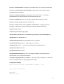
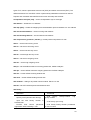
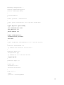
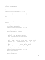
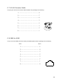
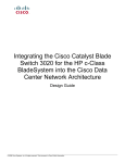
Figure 6-1 sna configuration example
400.1020.1000
Tokenring
500
IBM host
FEP
ROUTE A
ROUTE B
PU type 2.0
sdlc address
01
Configuration for Router A:
31
hostname RouterA
!
source-bridge ring-group 2000
dlsw local-peer peer-id 150.150.10.2
dlsw remote-peer 0 TCP 150.150.10.1
!
interface serial 8
IP address 150.150.10.2 255.255.255.192
clockrate 56000
!
interface tokening 0
no Ip address
ring-speed 16
source-bridge 500 1 2000
source-bridge spanning
Configuration for Router B
hostname RouterB
!
dlsw local-peer peer-id 150.150.10.1
dlsw remote-peer 0 TCP 150.150.10.2
!
interface serial 1
encapsulation hdlc
Ip address 150.150.10.1 255.255.255.192
no shutdown
!
interface serial 2
encapsulation sdlc
clock rate 9600
sdlc role primary
sdlc vmac 4000.9999.0100
sdlc address 01
sdlc xid 01 05d20066
sdlc partner 4000.1020.1000 01
sdlc dlsw 01
no shutdown
32
4.7 X.25 Protocol
The X.25 protocol is defines the connection between data terminal equipment (DTE) and
circuit-terminating equipment (DCE). X.25 is the protocol of point-to-point interaction between
DTE and DCE equipment.
DTE usually refers to the host or terminal at the user side and DCE usually refers to the
synchronous modem. DTE is connected with DCE directly. DCE is connected to a port of
packet switching exchange, and some connections are established between the packet
switching exchanges, thus forming the paths between different DTE.
With X.25, two DTE is able to communication to each other. Once a DTE device contacts
another to request a communication session then it means session communication is
established. If the request is accepted, the two systems begin full-duplex information transfer.
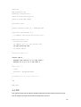
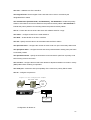
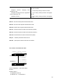
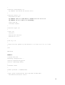
The following datagram is shown the relation between entities in X.25 network
图1-1 x.25网络模型
PSE
DCE
DTE
DCE
DTE
PSE
PSE
DCE
DTE
PSN
DTE
DCE
PSE
PSN
数据终端设备
数据电路终接设备
分组交换设备
分组交换网
The X.25 packet-switching protocol suits map to the lower three layers of the OSI (Open
system Interconnection) model. X.25 layer 3 (packet-layer protocol) describes the format of
packet used by the packet layer and the procedure of packet switching between two 3-layer
entities. X.25 layer 2 (link-layer protocol), also called LAPB (Link Access Procedure Balanced),
defines the format and procedure of interactive frames between DTE and DCE. X.25 layer 1
(physical-layer protocol) defines some physical and electrical characteristics in the connection
between DTE and DCE. The above relation is shown in the following diagram.
VC (virtual Circuits) is logic connection between two network devices. VC is a logic and
bi-directional path from one DTE device to another cross an X>25 network. There are two
33
types of VC, which is permanent virtual circuit (PVC) and switch virtual circuit (SVC). The
different between PVC and SVC is PVC is permanently established connections used for
frequent and consistent data transfers and not use call setup and call clear.
encapsulation x25 [dce | dte] – set the encapsulation style to X.25 type
x25 address – enable the X.21 address
x25 map [Qllc] – Create the mapping from the destination protocol address to X.121 address
x25 check-called-address – check incoming calls address
x25 check-calling-address – check outbound call address
x25 compression [ predictor | stacker ] – enable packet compression for x25
x25 lic – set the low incoming circuit
x25 hic – set the low incoming circuit
x25 ltc – set the low two-way circuit
x25 htc – set the high two-way circuit
x25 loc – set the low outgoing circuit
x25 hoc – set the high outgoing circuit
x25 ips – set the default maximum incoming packet size, default 128bytes
x25 ops – set the default maximum outgoing packet size. Default 128bytes
x25 win – set the default receiving window size
x25 wout – set the default sending window size
x25 modulus – setting X.25 packet number modulo. Either 8 or 128
x25 t20 – set DTE restart request retransmission timer
x25 facility Operation
Specify CUG (Closed User Group)
Input the user facility number in
hexadecimal
Perform flow control parameter
negotiation while initiating a call
Command
X.25
facility
group-number
facility-number
cug
X.25 facility byte-string
X.25 facility facility-number packetsize
in-size out-size
34
X.25 facility facility-number window size
in-size out-size
Request reverse
initiating a call
charging
while
Request throughput-level negotiation
while initiating a call
Network user ID
X.25 facility facility-number reverse
X.25 facility facility-number throughput
in out
X.25 facility facility-number throughput
in out
x25 t21 – set DTE call request retransmission timer
x25 t22 – set DTE reset request retransmission timer
x25 t23- set DTE clear request retransmission timer
x25 r20 – set the maximum number of the timeout (restart)
x25 r22 – set the maximum number of the timeout (restore)
x25 r23- set the Maximum number of the timeout (clear)
x25 pvc – create a permanent virtual circuit
x25 idle – specify the maximum idle time on interface
Two routers connected with cable
Figure 1-14 Two routers
connecting
Router1 dce
Router2dte
s1:10.1.1.1/16
X.121 87654321
X.121 12345678
s1:10.1.1.2/16
router configuration:(Use DCE cable)
Router1:
interface serial 1
encapsulation x25 dce
ip address 10.1.1.1 255.255.0.0
35
x25 address 87654321
x25 map ip 10.1.1.2 12345678
clockrate 9600
Router2:
interface serial 1
encapsulation x25 dte
ip address 10.1.1.2 255.255.0.0
x25 address 12345678
x25 map ip 10.1.1.1 87654321
Access packet switching network
Figure 1-16 Accessing packet switching network
Router1
s1:14.1.1.1/24
x121:14111
X25
s1:14.1.1.2/24
x121:14112
Router2
s1:14.1.1.3/24
x121:14113
Router3
Router1:
interface serial 1
encapsulation x25
ip address 14.1.1.1 255.255.255.0
x25 address 14111
x25 map ip 14.1.1.2 14112
x25 map ip 14.1.1.3 14113
Router2:
interface serial 1
encapsulation x25
ip address 14.1.1.2 255.255.255.0
x25 address 14112
x25 map ip 14.1.1.1 14111
x25 map ip 14.1.1.3 14113
Router3:
interface serial 1
encapsulation x25
ip address 14.1.1.3 255.255.255.0
x25 address 14113
x25 map ip 14.1.1.1 14111
36
x25 map ip 14.1.1.2 14112
Set up network with PVC
Router1:
interface serial 1
encapsulation x25
ip address 14.1.1.1 255.255.255.0
x25 address 14111
x25 ltc 3
x25 pvc 1 ip 14.1.1.2
x25 pvc 2 ip 14.1.1.3
Router2:
interface serial 1
encapsulation x25
ip address 14.1.1.2 255.255.255.0
x25 address 14112
x25 ltc 3
x25 pvc 1 ip 14.1.1.1
x25 pvc 2 ip 14.1.1.3
Router3:
interface serial 1
encapsulation x25
ip address 14.1.1.3 255.255.255.0
x25 address 14113
x25 ltc 3
x25 pvc 1 ip 14.1.1.1
x25 pvc 2 ip 14.1.1.2
4.8 Frame Relay Protocol
Frame relay protocol is provides multiplexing logical data conversations over a single physical
transmission link by assigning connection identify to each DTE devices.
Frame relay also supports PVC and SVC for data transfer between DTE devices. The different between
X.25 and frame relay is frame relay doesn’t have the windowing and retransmission strategies. Also
frame relay is only layer 2 protocol.
DLCI (data-link connection identifier) identifies the logical virtual circuit between DTE and frame
relay switch.
Frame Relay signaling
LMI (local management interface) is responsible for managing the connection and maintaining
status between the CPE devices and the FR switch.
37
The frame relay switch, which is responds one or more LMI types. There are three different
LMI types: cisco, ansi and q933a.
encapsulation frame-relay – encapsulation frame relay type on serial interface
frame-relay map ip protocol address dlci [broadcast | gateway-down | interface-down |
payload-compression] – configure static address mapping
frame-relay dlic-group – assign DLCI to some group
frame-relay fist-dlic – the number of first dlci (16-1007)
frame-relay intf-type – configure frame-relay interface type (dec, dte)
frame-relay inverse-arp – Enable/Disable inverse ARP
frame-relay lapf – set lapf parameter
frame-relay lmi-n391 – set the counter on PVC status enquiry message
frame-relay lmi-n392 – set the LMI error threshold
frame-relay lmi-n393 – set LMI monitor event counter
frame-relay lmi-t391 – set LMI T391 timer (0-4294967295)
frame-relay lmi-t392 – set DCE request confirm timer (3-30)
frame-relay lmi-type – set LMI type (ansi, cisco, q933a)
frame-relay local-dlci – set local dlci
frame-relay num-dlci – Assign the frame relay DLCI number
38
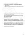
Figure 2-1 Configuration Example
E1:142.10.2.
142.10.2.6/
Router1
24
7/24
S1:192.1.1.1
/24
16
host_a
S1:192.1.1.3E1:142.10.4.
/24
7/24
17
FR
16
16
S1:192.1.1.2
/24
host_b
Router3
host_
c
Router2
142.10.4.6/
24
E1:142.10.3.
7/24
142.10.3.6/
24
(1) Router1 Configuration:
Router1>enable
Router1#conf term
Router1 (config)#interface s1
Router1 (config-if)#enca fram
Router1 (config-if)#no sh
Router1 (config-if)#Ip addr 192.1.1.1 255.255.255.0
Router1 (config-if)#fram first-dlci 16
Router1 (config-if)#fram map IP 192.1.1.2 16
Router1 (config-if)#fram map IP 192.1.1.3 17
Router1 (config-if)# exit
Router1 (config)#int e1
Router1 (config-if)# no shut
Router1 (config-if)# Ip addr 142.10.2.7 255.255.255.0
Router1 (config-if)# exit
Router1 (config)#IP route 142.10.3.0 255.255.255.0 192.1.1.2
Router1 (config)#IP route 142.10.4.0 255.255.255.0 192.1.1.3
Router1 (config)#exit
Router1#wr
(2) Router2 configuration:
Router2>enable
39
Router2#conf term
Router2 (config)#interface s1
Router2 (config-if)#enca fram
Router2 (config-if)#no sh
Router2 (config-if)#Ip addr 192.1.1.2 255.255.255.0
Router2 (config-if)#fram first-dlci 16
Router2 (config-if)#fram map IP 192.1.1.1 16
Router2 (config-if)#exit
Router2 (config)#int e1
Router2 (config-if)#no shut
Router2 (config-if)#Ip addr 142.10.3.7 255.255.255.0
Router2 (config-if)#exit
Router2 (config)#IP route 142.10.2.0 255.255.255.0 192.1.1.1
Router2 (config)#exit
Router2#wr
(2) Router3 configuration:
Router3>enable
Router3#conf term
Router3 (config)#interface s1
Router3 (config-if)#enca fram
Router3 (config-if)#no sh
Router3 (config-if)#Ip addr 192.1.1.3 255.255.255.0
Router3 (config-if)#fram first-dlci 16
Router3 (config-if)#fram map IP 192.1.1.1 16
Router3 (config-if)#exit
Router3 (config)#int e1
Router3 (config-if)#no shut
Router3 (config-if)#Ip addr 142.10.4.7 255.255.255.0
Router3 (config-if)#exit
Router3 (config)#IP route 142.10.2.0 255.255.255.0 192.1.1.1
Router3 (config)#exit
Router3#wr
40
Chapter 5 Security
5.1 Access-list
The purpose for access-list is packet filtering to control, which packets move through the network. Such
control can help limit network traffic and restrict network use by certain user or device.
Access-list is use as a packet filter, this function helps to limit network traffic and restrict network.
There are two general types of access lists:
Ø
Standard access-lists – The standard access-list is check the source address of packets.
Access-list number is start from 1-99
Ø
Extended access-list – The extended access-list is check for both source and destination packet
address and also check for specific protocols, port numbers and other parameters. Access-list
number is start from 100-199
access-list access-list number [permit | deny] – set the standard access-list’s rule.
ip access-group [in | out] – applies an existing access-list as an incoming or outgoing to an interface.
Access-list access-list number [permit | deny] protocol source-address source-wildcard
destination-address destination-wildcard [operator port] – set the extended access-list rule.
Standard access-list configuration example
ERT-805# show run
Building configuration ...
service password-encryption
service timestamps debug
!
hostname ERT-805
!
enable password 7 5EVbxkwzBvfT
!
username router password 7 qBjbURagjK0L
!
interface fastethernet 0/0
ip address 192.168.98.63 255.255.255.0
!
interface serial 0/0
encapsulation ppp
41
ip address 10.0.0.2 255.255.255.192
ip access-group 1 out
clockrate 48000
!
interface async 0/0
!
router rip
network 192.168.98.0
network 10.0.0.0
!
line vty 0 4
login
password 7 o2EUq2a6AFiY4D
!
ip route 0.0.0.0 0.0.0.0 10.0.0.1
!
access-list 1 permit host 192.168.98.62
access-list 1 permit host 192.168.98.63
access-list 1 permit host 192.168.98.64
access-list 1 permit host 10.0.0.0
access-list 1 deny any
!
end
ERT-805#
Extended access-list configuration example
ERT-805#
ERT-805# show run
Building configuration ...
service password-encryption
service timestamps debug
!
hostname ERT-805
!
42
enable password 7 5EVbxkwzBvfT
!
username router password 7 qBjbURagjK0L
!
interface fastethernet 0/0
ip address 192.168.98.63 255.255.255.0
!
interface serial 0/0
encapsulation ppp
ip address 10.0.0.2 255.255.255.192
ip access-group 100 out
clockrate 48000
!
interface async 0/0
!
router rip
network 192.168.98.0
network 10.0.0.0
!
line vty 0 4
login
password 7 o2EUq2a6AFiY4D
!
ip route 0.0.0.0 0.0.0.0 10.0.0.1
!
access-list 100 deny tcp 192.168.98.66 0.0.0.0 host 192.168.99.61 eq 21
access-list 100 permit ip any any
!
end
ERT-805#
43
5.2 NAT – Network Address Translation
IP address depletion is a main problem that facing in the public network. NAT (network address
translation) is a solution that allows the IP network of an organization to appear from the outside to use
different IP address then it own IP address.
Because the IP address is depletion therefore not all your hosts have global unique IP addresses. NAT
technology is translates the private IP address into public IP address before sending packets to the
outside network. There are two different methods, which is static and dynamic NAT.
ip nat inside source static local-ip golobal-ip – configure static NAT
ip nat [inside | outside] – Enable NAT on at least one and one outside interface by interface command
ip nat pool pool name srat-ip end-ip netmask [prefix-length | type rotary] - Define a pool of global
addresses to be allocated as needed.
Ip nat inside source list access-list no pool pool name [overload]- Establish dynamic source
translation, specifying the access list defined in the prior step. [option] overload, add the overload key
word to the command
Access-list access-list number permit source address [source wildcard bits]
Ip nat inside destination list access-list number pool pool name – Establish dynamic inside
destination translation,
Ip nat outside source list access-list no pool pool name - Establish dynamic outside source
translation, specifying the access list defined in the prior step
Show ip nat translation – display the active translations
Show ip nat statistics – display
Debug ip nat [detailed] – display a line of output for each packet that gets translated.
Clear ip nat translation * - to clear all translated entries.
Clear ip nat translation inside gip lip [outside <gip> <lip>] – clear both of inside or outside translation
Clear ip nat translation outside lip gip – clear outside translation
44
Static NAT Configuration
ERT-805# show run
Building configuration ...
service password-encryption
service timestamps debug
!
hostname ERT-805
!
enable password 7 5EVbxkwzBvfT
!
username router password 7 qBjbURagjK0L
!
interface fastethernet 0/0
ip address 192.168.98.63 255.255.255.0
ip nat inside
!
interface serial 0/0
encapsulation ppp
ip address 10.0.0.2 255.255.255.192
ip nat outside
clockrate 48000
!
interface async 0/0
!
router rip
network 192.168.98.0
network 10.0.0.0
!
line vty 0 4
login
password 7 o2EUq2a6AFiY4D
!
ip nat inside source static 192.168.98.62 10.0.1.1
!
access-list 1 permit 192.168.98.62 0.0.0.255
access-list 1 permit 10.0.0.2 0.0.0.255
!
end
45
ERT-805#
Figure of static NAT example result
ERT-805# show ip nat translations
Total 1 NAT translations
Pro Inside Local
Inside Global
Outside Global
---
192.168.98.62:0 10.0.1.1:0
TTL
ERT-805#
Dynamic NAT Configuration
ERT-805# show run
Building configuration ...
service password-encryption
service timestamps debug
!
hostname ERT-805
!
enable password 7 5EVbxkwzBvfT
username router password 7 qBjbURagjK0L
!
interface fastethernet 0/0
ip address 192.168.98.63 255.255.255.0
ip nat inside
!
interface serial 0/0
encapsulation ppp
ip address 10.0.0.2 255.255.255.192
46
ip address 10.0.1.1 255.255.255.192 secondary
ip nat outside
ip access-group 1 out
clockrate 48000
!
interface async 0/0
!
router rip
network 192.168.98.0
network 10.0.0.0
!
line vty 0 4
login
password 7 o2EUq2a6AFiY4D
!
ip nat pool overload 10.0.1.1 10.0.1.1 netmask 255.255.255.192
ip nat inside source list 1 pool overload overload
!
access-list 1 permit 192.168.98.62 0.0.0.255
access-list 1 permit 10.0.0.2 0.0.0.255 !
end
5.3 VPN - IPSec
IPSec is an implement secures the VPN (Virtual private Network). IPSec protocol includes AH
(Authentication Header), ESP (Encapsulation Security Payload) and IKE (Internet Key Exchange),
ISAKMP and transform.
Ipsec security architecture provides data confidentiality, data integrality, identity authentication,
anti-replay and DOS services. Security mechanism is implemented by AH(Authentication Header)
protocol and ESP(Encapsulation Security Payload) protocol. Key management is implemented by IKE.
The peers use SPI(Security Policy Index) to quote the dynamic negotiated SA(Security Association) to
provide data security.
crypto ipsec transform-set transform-name [transform 1] [transform 2] [transform 3]– to define the
transform set that combination of security protocols and algorithms.
mode [ tunnel | transport] – specify the mode for transform set. The default mode is tunnel.
Initialization-vector size [4 | 8] – to modify the length of the initialization-vector. The default is 8
47
crypto ipsec security-association lifetime [ kilobytes | seconds] – to modify the time value when
negotiating Ipsec security.
crypto map map-name map number [ ipsec-isakmp | ipsec-manual] – create a crypto map entry.
Ipsec-isakmp is used to establish the Ipsec security for protecting the traffic. Ipsec-maunal is not using
IKE to establish the ipsec secutiry.
crypto map map name map number ipsec-manual
Ø
Match address – specify the extended access list for crypto map
Ø
Transform-set - specify the transform sets that used with the crypto map entry
Ø
set peer [hostname | ip address] – specify the IPsec peer in a crypto map
Ø
set session key [inbound | outbound] [ah| esp] spi [ciper] hex-key-data [authenticator]
hex-key-data
-
inbound – set inbound session key
-
outbound- set outbound session key
-
ah – set AH protocol for Ipsec session key
-
ciper - Indicates that the key is to be used with the ESP encryption .
-
authenticator – (optional)
Indicates that the key is to be used with the ESP encryption
crypto map map name map number ipsec-isakmp
Ø
match address – specify the extended access list for crypto map
Ø
set peer [hostname | ip address] – specify the IPsec peer in a crypto map
Ø
set Transform-set - specify the transform sets that used with the crypto map entry
Ø
set pfs [group 1 | group 2] – specify the pfs setting. Group 1 is 769-bit and group 2 is 1024 bit
Ø
set security-association [level | lifetime]
-
level per-host - specify the IPSec security associations should be requested for each
source/destination host pair
-
lifetime [seconds | kilobytes] - override the global lifetime value that is used when
negotiating IPSec security.
crypto map dynamic-map dynamic-map name dynamic-seq no – Create dynamic-map entry.
crypto isakmp enable – enable Internet Key Exchange (IKE) at your router.
48
crypto isakmp key keystring address peer-address – configure preshared authentication key
crypto isakmp policy priority – to define Internet Key exchange (IKE) policy
-
hash
-
encryption
-
group
-
authentication
-
lifetime
show crypto ipsec sa – shows current connections and information regarding encrypted and
decrypted packets.
show crypto isakmp sa – view all current IKE security association at a peer.
clear crypto isakmp sa – clears the phase 1
clear crypto ipsec sa – clears the phase 2
debug crypto isakmp - Displays the ISAKMP negotiations of Phase 1.
Router 1
ERT_805# show run
Building configuration ...
description fault
service password-encryption
service timestamps debug
!
hostname ERT_805
!
enable password 7 3EDRIxtqRWCA
!
username router password 7 65WeJR6evnrR3mP
crypto ipsec transform-set transform-1 esp-3des esp-md5-hmac
!
crypto map dynmap 1 ipsec-isakmp
set transform-set transform-1
set peer 10.0.0.2
49
match address 100
!
crypto isakmp policy 1
authentication pre-share
group 1
hash md5
!
crypto isakmp key 12345678 address 10.0.0.2 255.255.255.192
!
interface fastethernet 0/0
ip address 192.168.99.64 255.255.255.0
!
interface serial 0/0
encapsulation ppp
ip address 10.0.0.1 255.255.255.192
crypto map dynmap
clockrate 48000
!
interface async 0/0
!
line vty 0 5
login
password 7 wAVcXxom8sGSOA
!
ip route 0.0.0.0 0.0.0.0 10.0.0.2
!
access-list 100 permit ip 192.168.99.0 0.0.0.255 192.168.98.0 0.0.0.255
!
end
ERT_805#
Router 2
router# show run
Building configuration ...
service password-encryption
service timestamps debug
50
!
hostname router
!
enable password 7 7JDUhlA4A907
!
username scott password 7 phTLTNmZFcwY3D
crypto ipsec transform-set transform-1 esp-3des esp-md5-hmac
!
crypto map dynmap 1 ipsec-isakmp
set transform-set transfrom-1
set peer 10.0.0.1
match address 100
!
crypto isakmp policy 1
authentication pre-share
group 1
hash md5
!
crypto isakmp key 12345678 address 10.0.0.1 255.255.255.192
!
interface fastethernet 0/0
ip address 192.168.98.63 255.255.255.0
!
interface serial 0/0
encapsulation ppp
ip address 10.0.0.2 255.255.255.192
crypto map dynmap
!
interface async 0/0
!
line vty 0 4
login local
!
ip route 0.0.0.0 0.0.0.0 10.0.0.1
!
access-list 100 permit ip 192.168.98.0 0.0.0.255 192.168.99.0 0.0.0.255
!
end
51
router#
router# debug crypto isakmp
router#
22:34.011 Crypto ISAKMP debugging is on
router# term
router# terminal m
router# terminal monitor
router# 23:03.993 IPSEC: SEND KEEYALIVE ON PEER 10.0.0.2
23:03.993 recv msg type=331, msg=08 0a 00 00 01 0a 00 00 02
23:03.993 recv Ipsec Msg
23:03.994 recv DPD req
23:03.994 creat a DPD struct
23:03.994 send R_U_THERE=00 00 00 20 00 00 00 01 01 10 8d 28 38 8b 12 ad e8 16
23:03.994 7f f7 5c 1c 4b 9b 2e 25 69 1a 01 27 c6 38
23:03.996 send msg=38 8b 12 ad e8 16 7f f7 5c 1c 4b 9b 2e 25 69 1a 08 10 05 01
23:03.996 b4 52 6e 59 00 00 00 54 8d da 57 8a 07 85 b6 49 62 10 70 a6 a8 df f4
23:03.996 ed d1 b7 fd e1 99 8a 60 d8 68 d8 e6 66 e8 f8 90 91 4c db 16 e6 e8 a5
23:03.996 f4 42 26 12 c5 c5 d7 85 ec 5c 7d 60 a1 4a 98 63 57 64
23:03.997 start IKE DPD timer conn= 17
23:03.049 recv msg type=100, msg=29 01 f4 01 f4 0a 00 00 02 0a 00 00 01 38 8b
1
23:03.049 2 ad e8 16 7f f7 5c 1c 4b 9b 2e 25 69 1a 08 10 05 01 b3 e7 a6 94 00
0
23:03.049 0 00 54 ef d8 1c 37 63 4f e6 27 f2 63 bd 03 93 b0 db 66 4a c2 d5 d6
e
23:03.049 c 01 74 ba d5 a1 88 1f 9e 6c 8a 40 5c f9 03 17 52 cd 98 c4 59 2f eb
1
23:03.049 6 70 1b 20 0e 0d ed 30 44 95 0d 17 39
23:03.050 recv ISAKMP:38 8b 12 ad e8 16 7f f7 5c 1c 4b 9b 2e 25 69 1a 08 10 05
23:03.050 01 b3 e7 a6 94 00 00 00 54 ef d8 1c 37 63 4f e6 27 f2 63 bd 03 93 b0
23:03.050 db 66 4a c2 d5 d6 ec 01 74 ba d5 a1 88 1f 9e 6c 8a 40 5c f9 03 17 52
23:03.050 cd 98 c4 59 2f eb 16 70 1b 20 0e 0d ed 30 44 95 0d 17 39, len=84
52
router# show crypto ipsec sa
interface: serial0/0
Crypto map tag:dynmap, local addr:10.0.0.1
Local ident (addr/mask/prot/port):192.168.99.0/255.255.255.0/0/0
Remotel ident (addr/mask/prot/port):192.168.98.0/255.255.255.0/0/0
PERMIT,flags={origin_is_acl,}
Current Peer:10.0.0.2
#pkts encaps:1160 ,pkts encrypts:1160, pkts digest:1160
#pkts decaps:1160 ,pkts decrypts:1160, pkts verify:1160
#pkts send errrors:0 ,pkts receive errors:0
local crypto endpt.:10.0.0.1, remote crypto endpt.:10.0.0.2
inbound esp sas:
Spi: 0X103(259)
sastate_mature! p_sa=259
transform: esp-md5-hmac, esp-3des
In use setting:{Tunnel}
crypto map: dynmap
sa timing: remaining key lifetime (k/sec): (313021/3345)
IV size: 8 bytes
replay detection support: Y
inbound pcp sas:
outbound esp sas:
Spi: 0X103(259)
sastate_mature!
p_sa=259
in use!
transform: esp-md5-hmac, esp-3des
In use setting:{Tunnel}
crypto map: dynmap
sa timing: remaining key lifetime (k/sec): (313026/3345)
IV size: 8 bytes
replay detection support: Y
outbound pcp sas:
router#
53
Configure Ipsec Manual between routers
Router 2
Router 1
Si
eth:192.168.98.63
Si
s0/0 10.0.0.2
s0/0 10.0.0.1
eth:192.168.99.64
Router 1 configuration
ERT-805# show run
Building configuration ...
service password-encryption
service timestamps debug
!
hostname ERT-805
!
enable password level 15 7 EJketQjD8uBh
!
crypto ipsec transform-set test esp-des
!
crypto map dynmap 1 ipsec-manual
set transform-set test
set peer 10.0.0.1
set session-key inbound esp 256 cipher 1234567890ABCDEF
set session-key outbound esp 256 cipher 0123456789ABCDEF
match address 100
!
no crypto isakmp enable
!
interface fastethernet 0/0
ip address 192.168.98.63 255.255.255.0
!
interface serial 0/0
encapsulation ppp
ip address 10.0.0.2 255.255.255.192
crypto map dynmap
clockrate 48000
!
interface async 0/0
54
!
router rip
network 192.168.98.0
network 10.0.0.0
!
line vty 0 4
login
password 7 iFEdTlElgPbW4D
!
!
access-list 100 permit ip 192.168.98.0 0.0.0.255 192.168.99.0 0.0.0.255
!
end
Router 2 configuration
ERT-805#
router# show run
Building configuration ...
service password-encryption
service timestamps debug
!
hostname router
!
enable password level 15 7 aNTUS0QSfz8T
!
crypto ipsec transform-set test esp-des
!
crypto map dynmap 1 ipsec-manual
set transform-set test
set peer 10.0.0.2
set session-key inbound esp 256 cipher 0123456789ABCDEF
set session-key outbound esp 256 cipher 1234567890ABCDEF
match address 100
!
no crypto isakmp enable
!
interface fastethernet 0/0
55
ip address 192.168.99.64 255.255.255.0
!
interface serial 0/0
encapsulation ppp
ip address 10.0.0.1 255.255.255.192
crypto map dynmap
!
interface async 0/0
!
router rip
network 192.168.99.0
network 10.0.0.0
!
line vty 0 4
login
password 7 hd3cpRj4s14LeA
!
ip route 0.0.0.0 0.0.0.0 10.0.0.2
!
access-list 100 permit ip 192.168.99.0 0.0.0.255 192.168.98.0 0.0.0.255
!
end
router#
Dynamic example
Router 1- central router
service password-encryption
service timestamps debug
!
hostname router
!
enable password 7 St3Yuxw1NBTq
!
crypto ipsec transform-set scott esp-des ah-md5-hmac
!
crypto dynamic-map dy 1
set transform-set scott
56
match address 100
!
crypto map mm 1 ipsec-isakmp dynamic dy
crypto isakmp policy 1
authentication pre-share
hash md5
!
crypto isakmp key 1234 address 10.0.0.2 255.255.255.192
!
interface fastethernet 0/0
ip address 192.168.99.64 255.255.255.0
ip address 192.168.99.64 255.255.255.0
!
interface serial 0/0
encapsulation ppp
ip address 10.0.0.1 255.255.255.192
crypto map mm
clockrate 48000
!
interface async 0/0
!
router rip
network 192.168.99.0
network 10.0.0.0
!
line vty 0 4
login
password 7 kdWL6UXPkdPV/B
!
ip route 0.0.0.0 0.0.0.0 serial 0/0
!
access-list 100 permit ip 192.168.99.0 0.0.0.255 192.168.98.0 0.0.0.255
!
end
router#
Router 2 – remote side
57
Building configuration ...
service password-encryption
service timestamps debug
!
hostname ERT-805
!
enable password 7 uh4a5s35v9i6
!
crypto ipsec transform-set scott esp-des ah-md5-hmac
!
crypto map mm 1 ipsec-isakmp
set transform-set scott
set peer 10.0.0.1
match address 100
!
crypto isakmp policy 1
authentication pre-share
hash md5
!
crypto isakmp key 1234 address 10.0.0.1 255.255.255.192
!
interface fastethernet 0/0
ip address 192.168.98.63 255.255.255.0
!
interface serial 0/0
encapsulation ppp
ip address 10.0.0.2 255.255.255.192
crypto map mm
!
interface async 0/0
!
router rip
network 10.0.0.0
network 192.168.98.0
!
line vty 0 4
login
password 7 3Z4SNtmYpBT6BC
58
!
ip route 0.0.0.0 0.0.0.0 serial 0/0
!
access-list 100 permit ip 192.168.98.0 0.0.0.255 192.168.99.0 0.0.0.255
!
end
ERT-805#
router# show crypto ipsec sa
interface: serial0/0
Crypto map tag:dynmap, local addr:10.0.0.1
Local ident (addr/mask/prot/port):192.168.99.0/255.255.255.0/0/0
Remotel ident (addr/mask/prot/port):192.168.98.0/255.255.255.0/0/0
PERMIT,flags={origin_is_acl,}
Current Peer:10.0.0.2
#pkts encaps:1160 ,pkts encrypts:1160, pkts digest:1160
#pkts decaps:1160 ,pkts decrypts:1160, pkts verify:1160
#pkts send errrors:0 ,pkts receive errors:0
local crypto endpt.:10.0.0.1, remote crypto endpt.:10.0.0.2
inbound esp sas:
Spi: 0X103(256)
sastate_mature! p_sa=256
transform: esp-des
In use setting:{Tunnel}
crypto map: dynmap
no sa timing:
IV size: 8 bytes
replay detection support: Y
inbound pcp sas:
outbound esp sas:
Spi: 0X103(256)
sastate_mature!
p_sa=256
in use!
transform: esp-des
In use setting:{Tunnel}
59
crypto map: dynmap
no sa timing:
IV size: 8 bytes
replay detection support: Y
outbound pcp sas:
router#
GRE Example
Router 1
ERT-805> enable
Password:
ERT-805# show run
Building configuration ...
service password-encryption
service timestamps debug
!
hostname ERT-805
!
enable password 7 at1a2V/tbD6b
!
crypto ipsec transform-set marc esp-3des ah-md5-hmac
initialization-vector size 8
!
crypto dynamic-map dy 1
set transform-set marc
match address 100
!
crypto map mm 1 ipsec-isakmp dynamic dy
crypto isakmp policy 1
authentication pre-share
hash sha
!
crypto isakmp key 1234 address 0.0.0.0 0.0.0.0
60
!
interface fastethernet 0/0
ip address 192.168.99.64 255.255.255.0
!
interface serial 0/0
encapsulation hdlc
ip address 130.0.1.2 255.255.0.0 tunnel 10.0.0.1 10.0.0.2
ip address 10.0.0.1 255.0.0.0 secondary
crypto map mm
clockrate 128000
!
interface async 0/0
!
router rip
version 1
network 192.168.99.0
network 10.0.0.0
!
line vty 0 31
!
access-list 100 permit ip 192.168.99.0 0.0.0.255 10.0.0.0 0.0.0.255
!
end
ERT-805#
Router 2
router# show run
Building configuration ...
service password-encryption
service timestamps debug
!
hostname router
!
enable password 7 wonRBhc01DcE
!
crypto ipsec transform-set marc esp-3des ah-md5-hmac
initialization-vector size 8
61
!
crypto map mm 1 ipsec-isakmp
set transform-set marc
set peer 10.0.0.1
match address 100
!
crypto isakmp policy 1
authentication pre-share
hash sha
!
crypto isakmp key 1234 address 10.0.0.1 255.0.0.0
!
interface fastethernet 0/0
ip address 192.168.98.63 255.255.255.0
ip nat inside
!
interface serial 0/0
encapsulation hdlc
ip address 130.0.1.1 255.255.0.0 tunnel 10.0.0.2 10.0.0.1
ip address 10.0.0.2 255.0.0.0 secondary
ip address 10.0.0.3 255.0.0.0 secondary
ip nat outside
crypto map mm
!
interface async 0/0
!
router rip
network 10.0.0.0
network 192.168.98.0
!
line vty 0 4
login
password 7 k2CZPVdrqEggyC
!
ip route 0.0.0.0 0.0.0.0 serial 0/0
ip nat pool overload 10.0.0.3 10.0.0.3 netmask 255.0.0.0
ip nat inside source list 1 pool overload overload
!
62
access-list 1 permit 192.168.98.62 0.0.0.255
access-list 100 permit ip 10.0.0.0 0.0.0.255 192.168.99.61 0.0.0.255
!
end
router#
ERT-805# show ip route
Codes: A--all O--ospf S--static R--rip C--connected E--egp T--tunnel
o--cdp D--EIGRP, EX--EIGRP external, O--OSPF, IA--OSPF inter area
N1--OSPF NSSA external type 1, N2--OSPF NSSA external type 2
E1--OSPF external type 1, E2--OSPF external type 2
[Distance/Metric] g<Group#>
C
10.0.0.0/8 [0/1] via 10.0.0.1 serial0/0* act
C
130.0.0.0/16 [0/1] via 130.0.1.2 Tunnel<serial0/0>* act
192.168.98.0/24 [120/1]
R
via 10.0.0.3, ttl=150, serial0/0 act
R
via 10.0.0.2, ttl=150, serial0/0 act
C
192.168.99.0/24 [0/1] via 192.168.99.64 fastethernet0/0* act
ERT-805#
5.4 Firewall- Context-Based Access Control (CBAC)
Security is an important issue in IT world. Most of people may know about firewall, it is use to prevent
unauthorized, external individuals from gaining access into your network. Context-Based Access
Control (CBAC) is a new feature technology that turns your router into an effective and robust firewall.
CBAC is includes the following features:
Ø
Basic and advanced traffic filtering
Ø
Security serer support
Ø
Network Address translation
Ø
Cisco encryption technology
Ø
IPSec network security
63
Ø
Neighbor router authentication
Ø
Even logging
CBAC uses timeout and thresholds to determine how long to manage information for a session and
when to drop the session that connects is failed. CBAC is only check with TCP and UDP but not ICMP.
The following example is showing the user how to configure CBAC.
ip inspect alert-off – disable alert
ip audit-trail – enable the logging of session information
ip dns-timeout – specify timeout for DNS
ip hashtable-size – specify size of hashtable
ip max-incomplete [low | high] – specify the number of incomplete connection before clamping
ip one-minute [low | high] – specify the rate of new unestablished TCP session that will cause the
software to stop/start deleting half-open session
ip inspect udp idle-time – specify the idle timeout for udp
ip inspect tcp [finwait-time | idle-time | max-incomplete | synwait-time] – configure timeout value
for tcp connections
-
finwait-time – specify timeout for TCP connections after firewall detect a FIN exchange
-
idle-time – specify the TCP connection idle-timeout
-
max-incomplete host half-open session block-time- specify max half-open connection per
host
-
synwait-time – specify the timeout for TCP connects after SYN
ip inspect name name of inspect [protocol] timeout – configure CBAC inspection protocol eg tcp,
http, udp, smtp and more.
show ip inspect all – show all CBAC configuration and all existing session
show ip inspect config – show the complete CBAC inspection configuration
show ip inspect name inspect name –show a particular inspection rule
64
show ip inspect interface – show interface configuration with inspection rule and access-list
show ip inspect session – display the current session that have been established
debug ip inspect events – display the information about CBAC events
debug ip inspect object-creation – display the message about object that create by CBAC.
debug ip inspect object-deletion – display the message about object being delete by CBAC
debug ip inspect protocol – display the information about protocol eg http, tcp, ftp…etc
Configuration Example
Building configuration...
service password-encryption
service timestamps debug
!
hostname router
!
enable password 7 Pl2cGlY8liD4
!
interface fastethernet 0/0
ip address 192.168.98.63 255.255.255.0
!
interface serial 0/0
encapsulation ppp
ip address 10.0.0.2 255.255.255.192
ip access-group 100 in
ip inspect test out
!
interface async 0/0
!
router rip
network 10.0.0.0
network 192.168.98.0
!
line vty 0 5
login
password 7 tF4VZx7eRx5VcC
!
65
ip route 0.0.0.0 0.0.0.0 10.0.0.1
ip inspect audit-trail
ip inspect max-incomplete low 100
ip inspect max-incomplete high 120
ip inspect one-minute low 100
ip inspect one-minute high 120
ip inspect tcp synwait-time 50
ip inspect name test http
ip inspect name test ftp
ip inspect name test udp
ip inspect name test tcp
ip inspect name test smtp
ip inspect name test fragment maximum 100
!
access-list 100 permit tcp host 192.168.99.61 host 192.168.98.62
access-list 100 deny tcp any any
access-list 100 deny udp any any
access-list 100 permit ip any any
!
end
router#
router# show ip inspect sessions
CBAC built 2 sessions:
dns: 192.168.98.62(1034)=>168.95.1.1(53) state:UDP_CLIENT_SYN (0X40227)
dns: 192.168.98.62(1034)=>139.175.55.244(53) state:UDP_CLIENT_SYN (0X40228)
CBAC built 1 sessions:
dns: 192.168.98.62(1034)=>168.95.1.1(53) state:UDP_CLIENT_SYN (0X40229)
router#
router# debug ip inspect tcp
router# terminal monitor
25:54.237
CBAC: RCV TCP packet 192.168.98.62:1412=>192.168.99.61:21
fastethern
25:54.237 et0/0
25:54.263
CBAC: RCV TCP packet 192.168.99.61:21=>192.168.98.62:1412 serial0/0
25:54.265
CBAC: RCV TCP packet 192.168.98.62:1412=>192.168.99.61:21
fastethern
25:54.265 et0/0
66
25:54.379
CBAC: RCV TCP packet 192.168.99.61:21=>192.168.98.62:1412 serial0/0
25:54.569
CBAC: RCV TCP packet 192.168.98.62:1412=>192.168.99.61:21
fastethern
25:54.569 et0/0
25:58.813
CBAC: RCV TCP packet 192.168.98.62:1412=>192.168.99.61:21
fastethern
25:58.813 et0/0
25:58.850
CBAC: RCV TCP packet 192.168.99.61:21=>192.168.98.62:1412 serial0/0
25:58.975
CBAC: RCV TCP packet 192.168.98.62:1412=>192.168.99.61:21
fastethern
25:58.975 et0/0
25:59.714
CBAC: RCV TCP packet 192.168.98.62:1412=>192.168.99.61:21
fastethern
25:59.714 et0/0
25:59.873
CBAC: RCV TCP packet 192.168.99.61:21=>192.168.98.62:1412 serial0/0
26:00.054
CBAC: RCV TCP packet 192.168.99.61:21=>192.168.98.62:1412 serial0/0
26:00.176
CBAC: RCV TCP packet 192.168.98.62:1412=>192.168.99.61:21
fastethern
26:00.176 et0/0
router# debug ip inspect object-creation
27:05.711 INSPECT Object Creations debugging is on
27:14.453
CBAC: creat a session table (0x40230)
27:14.453
CBAC: building a new tcp session
28:37.100
CBAC: creat a session table (0x40231)
28:37.100
CBAC: building a new udp session (0x40231)
28:41.098
CBAC: creat a session table (0x40232)
28:41.098
CBAC: building a new udp session (0x40232)
28:44.123
CBAC: creat a session table (0x40233)
28:44.124
CBAC: building a new udp session (0x40233)
28:48.127
CBAC: creat a session table (0x40234)
28:48.128
CBAC: building a new udp session (0x40234)
28:54.362
CBAC: creat a session table (0x40235)
28:54.362
CBAC: building a new tcp session
router#
router# debug ip inspect object-deletion
29:33.138 INSPECT Object Deletions debugging is on
67
29:37.201
CBAC: delete a session table (40235)
29:40.059
CBAC: delete a session table (40232)
29:45.059
CBAC: delete a session table (40230)
29:58.059
CBAC: delete a host session table
29:58.059
CBAC: delete a session table (40236)
5.5 Radius Security (AAA)
AAA (Authentication Authorization Accounting) is the way that allows access to the network server and what
services they are allow using once they have access.
radius-server host ip address of radius server [acc-port | auth-port] – specify the IP address of the
RADIUS server.
radius-server key – specify the key between the access point and RADIUS server
radius-server retransmit – specify the number of times the access point sends the request to server
radius-server timeout – specify the number of seconds that access point waits for a reply to a
RADIUS request before resending the request.
Radius-server deadtime – specify the time that mark as “dead” when RADIUS server fail to respond to
authentication request.
aaa authentication ppp authentication name [local | radius] – specify aaa authentication methods for
use on serial interface and running ppp
aaa accounting network name accounting list start-stop radius – runs start-stop accounting for all
packet service and use radius server.
ppp pap send-username pap username password pap password – enable the remote pap support
for an interface and send the pap authentication request packets.
ppp authentication [chap | pap] – specify the chap or pap authentication on interface
ppp chap hostname – configure the chap hostname
ppp chap password – configure the chap password
ppp compress [predictor | stacker] – configure predictor or stacker compress on the interface
Configuration Example
PAP example
Router 1
68
router# show run
Building configuration ...
service password-encryption
service timestamps debug
!
hostname router
!
enable password 7 St3Yuxw1NBTq
!
aaa authentication ppp scott radius
aaa accounting network scott start-stop radius
username scott password 7 1clZ5Mnm-XEu
!
interface fastethernet 0/0
ip address 192.168.99.64 255.255.255.0
!
interface serial 0/0
encapsulation ppp
ip address 10.0.0.1 255.255.255.192
ppp authentication pap scott
ppp accounting scott
clockrate 48000
!
interface async 0/0
!
router rip
network 192.168.99.0
network 10.0.0.0
!
line vty 0 4
login
password 7 kdWL6UXPkdPV/B
!
ip route 0.0.0.0 0.0.0.0 serial 0/0
radius-server key 7 DRjQtY26F/tc
radius-server deadtime 2
radius-server retransmit 4
69
radius-server host 192.168.99.63
!
end
router#
Router 2
ERT-805> enable
Password:
ERT-805# show run
Building configuration ...
service password-encryption
service timestamps debug
!
hostname ERT-805
!
enable password 7 uh4a5s35v9i6
!
interface fastethernet 0/0
ip address 192.168.98.63 255.255.255.0
!
interface serial 0/0
encapsulation ppp
ip address 10.0.0.2 255.255.255.192
ppp pap sent-username scott password 7 ZVnRE6gNg/-O
!
interface async 0/0
!
router rip
network 10.0.0.0
network 192.168.98.0
!
line vty 0 4
login
password 7 3Z4SNtmYpBT6BC
!
70
ip route 0.0.0.0 0.0.0.0 serial 0/0
!
end
ERT-805#
CHAP Example
Router 1
router# show run
Building configuration ...
service password-encryption
service timestamps debug
!
hostname router
!
enable password 7 St3Yuxw1NBTq
!
aaa authentication ppp scott radius
aaa accounting network scott start-stop radius
username scott password 7 1clZ5Mnm-XEu
!
interface fastethernet 0/0
ip address 192.168.99.64 255.255.255.0
!
interface serial 0/0
encapsulation ppp
ip address 10.0.0.1 255.255.255.192
ppp authentication chap scott
ppp accounting scott
clockrate 48000
!
interface async 0/0
!
router rip
network 192.168.99.0
network 10.0.0.0
71
!
line vty 0 4
login
password 7 kdWL6UXPkdPV/B
!
ip route 0.0.0.0 0.0.0.0 serial 0/0
radius-server key 7 DRjQtY26F/tc
radius-server deadtime 2
radius-server retransmit 4
radius-server host 192.168.99.63 acct-port 1646 auth-port 1645
!
end
router#
Router 2
ERT-805> enable
Password:
Password:
ERT-805# show run
Building configuration ...
service password-encryption
service timestamps debug
!
hostname ERT-805
!
enable password 7 uh4a5s35v9i6
!
interface fastethernet 0/0
ip address 192.168.98.63 255.255.255.0
!
interface serial 0/0
encapsulation ppp
ip address 10.0.0.2 255.255.255.192
ppp chap hostname scott
ppp chap password 7 vI3c39uvvCdX
72
!
interface async 0/0
!
router rip
network 10.0.0.0
network 192.168.98.0
!
line vty 0 4
login
password 7 3Z4SNtmYpBT6BC
!
ip route 0.0.0.0 0.0.0.0 serial 0/0
!
end
ERT-805#
Debug radius
13:51.914 #Line serial0/0 Protocol Up
13:51.921 Radius: Send to 192.168.99.63:1646, Accounting_Request, id 0xfe, len
13:51.921 52
13:51.922
Attribute type: ATTR_USER_NAME, len: 7
13:51.922
13:51.923
value: 73 63 6f 74 74
Attribute type: ATTR_CLASS, len: 6
13:51.923
13:51.923
value: 61 14 6 ae
Attribute type: ATTR_ACCT_STATUS_TYPE, len: 6
13:51.924
13:51.924
value: 0 0 0 1
Attribute type: ATTR_ACCT_SESSION_ID, len: 6
13:51.925
13:51.925
value: 0 0 0 5
Attribute type: ATTR_USER_NAME, len: 7
13:51.925
value: 73 63 6f 74 74
13:51.931 Radius: Received from 192.168.99.63:1646, Accounting_Response, id 0xf
13:51.931 e, len 20
13:51.931 Radius: No attributes in Message
73
Chapter 6 QOS
Quality of service (QOS) is use to improve the network efficiency. ERT-805 provides some different
QOS, which are CAR, Policy-based Routing, Weight fair queuing and class-map
6.1 CAR – Committed Access Rate
CAR (Committed Access Rate) is allows user to limit the output transmission rate on an interface. CAR
provides two qualities of service functions:
Ø
Bandwidth management through rate limit
Ø
Packet classification through IP precedence
The following example is shows how to configuration CAR:
rate-limit output [access-group] access-list no bps Normal bust number Maximum bust number
conform-action conform action exceed-action exceed action – configure CAR and distributed
policies.
output
access-group
Applies this CAR traffic policy to packets sent on this output
interface.
(Optional) Applies this CAR traffic policy to the specified access
list.
bps
Average rate, in bits per second (bps).
Normal burst bytes
Normal burst size, in bytes.
Maximun bust bytes
Excess burst size, in bytes.
•
continue—Evaluates the other rate-limit
conform-action
•
drop—Drops the packet.
conform-action
•
transmit—Sends the packet.
•
continue—Evaluates the other rate-limit .
•
drop—Drops the packet.
•
transmit—Sends the packet.
exceed-action exceed-action
74
Violate-action
•
continue – Evaluates the other rate-limit
•
drop – Drops the packet
•
transmit – Sends
show interface rate-limit – display information about CAR for an interface
Configuration Example
router# show run
Building configuration ...
service password-encryption
service timestamps debug
!
hostname ERT-805
!
enable password 7 uh4a5s35v9i6
!
interface fastethernet 0/0
ip address 192.168.98.63 255.255.255.0
!
interface serial 0/0
encapsulation ppp
ip address 10.0.0.2 255.255.255.192
rate-limit output access-group 100 9600 24000 32000 conform-action transmit
exceed-action drop
rate-limit output access-group 101 8000 24000 32000 conform-action transmit
exceed-action drop
rate-limit output 10000 16000 24000 conform-action transmit exceed-action drop
!
interface async 0/0
!
router rip
network 10.0.0.0
network 192.168.98.0
!
line vty 0 4
login
75
password 7 3Z4SNtmYpBT6BC
!
ip route 0.0.0.0 0.0.0.0 serial 0/0
!
access-list 100 permit tcp any any eq www
access-list 101 permit tcp any any eq ftp
!
end
router#
router# show interface s0/0 rate-limit
Output
matches: access-group 100
params: 9600 bps, 24000 limit, 32000 extended limit
conformed 3582 packets, 219373 bytes; action: transmit
exceeded 0 packets, 0 bytes; action: drop
last packet: 2ms ago, current burst: 23939 bytes
conformed 2014 bps, exceeded 0 bps
Output
matches: access-group 101
params: 8000 bps, 24000 limit, 32000 extended limit
conformed 37 packets, 2489 bytes; action: transmit
exceeded 0 packets, 0 bytes; action: drop
last packet: 157119ms ago, current burst: 23918 bytes
conformed 0 bps, exceeded 0 bps
Output
matches: all traffic
params: 10000 bps, 16000 limit, 24000 extended limit
conformed 2450 packets, 2322667 bytes; action: transmi
exceeded 22 packets, 33462 bytes; action: drop
last packet: 1ms ago, current burst: 15939 bytes
conformed 122 bps, exceeded 0 bps
router#
76
6.2 Policy-based Routing
PBR (policy-based routing) is allows user manually to defined policy that how to received packets
should be routed and also allows user to identify packets using several attributes to specify the next
hop to which the packet should be sent.
route-map map-name [deny | permit] sequence-number – to define the condition for policy routing
match ip address access-list number – to specify the condition by access-list
match length min max – to establish criteria based on packet length.
set ip next-hop ip address for next hop – to specify the next-hop router in path that packets should be
forward.
ip policy route-map map name – identify a route map to use for policy routing on an interface.
set interface type of interface – specify a list of interface which the packets can be routed.
traceroute Trace route to destination address - discovers the routes packets follow when traveling to
their destinations
Configuration Example
router# show run
Building configuration ...
service password-encryption
service timestamps debug
!
hostname router
!
enable password 7 wonRBhc01DcE
!
interface fastethernet 0/0
ip address 192.168.98.63 255.255.255.0
!
interface serial 0/0
encapsulation hdlc
ip address 10.0.0.2 255.0.0.0
ip policy route-map richard
!
interface async 0/0
!
77
router rip
version 2
network 10.0.0.0
network 192.168.98.0
!
line vty 0 4
login
password 7 k2CZPVdrqEggyC
!
route-map richard
match ip address 1
set interface serial 0/0
set ip next-hop 10.0.0.1
!
access-list 1 permit 192.168.98.62 0.0.0.255
!
end
router#
6.3 Class-map and policy-map
Class-map command is a global command which is for specify a traffic class containing match criteria.
This command is used to create traffic class only the traffic policy must use the other command that is
policy-map to specify.
The traffic class is associated with traffic policy when the class command is used. After entering the
class command, you are automatically in policy-map class configuration mode, which is where the
QoS policies for the traffic policy are defined. The following example is shows how to configure
Class-map.
class-map [match-all | match-any] class-map name – specify the traffic class.
-
match-all – when all of the match criteria in class-map must met for traffic entering that
specify in class-map.
-
match-any – when one of the match criteria in class-map must met for traffic entering that
specify in class-map
match access-group access-list no – specify the access-list index
78
any – match any packets
match input-interface – specify an input interface to match
match class-map class-map name – specify the traffic class as a match criterion.
match ip rtp lower bound of UDP destination prot – configure class-map that use rtp protocol port as
match criterion
match protocol ip [ tcp | upd] tcp/udp port number – specify the class-map that use two different
protocol as match criterion.
policy-map map name – configure the policies for class whose match criteria for a class.
class class-map name – specify the policy criteria
bandwidth [ percent | remaining | 8-2000000 ] – specify the bandwidth for a class that belong to a
policy map
fair-queue – specify the number of dynamic queues
shape [average | max-buffer | peak ] – specify the traffic shaping
queue-limit packets – Specify the maximum number of packets that queue for a traffic class
priority [percent | 8-2000000 ] – specify the guaranteed allow bandwidth in kilo bits or percent for
priority traffic
police [access-group | bps per second bps burst-normal burst-max ] conform-action action
exceed-action action violate-action action – Specify the maximum bandwidth usage by a traffic class.
show policy-map interface interface – display configuration and statistics of the policy that attached to
an interface
show class-map – display all configuration traffic policy
show class-map class-map name – display the information of user-specific traffic policies.
Configuration Example
router# show run
Building configuration ...
service password-encryption
service timestamps debug
!
hostname router
!
79
enable password 7 wonRBhc01DcE
!
class-map match-any test
match access-group 101
match protocol ip tcp 80
match input-interface serial 0/0
!
class-map match-any test1
match access-group 102
match protocol ip tcp 80
match input-interface serial 0/0
!
policy-map richard
class test
bandwidth percent 60
queue-limit 2
!
class test1
bandwidth percent 40
queue-limit 2
!
!
interface fastethernet 0/0
ip address 192.168.98.63 255.255.255.0
!
interface serial 0/0
encapsulation hdlc
ip address 10.0.0.2 255.0.0.0
service-policy Richard
!
interface async 0/0
!
router rip
version 1
network 192.168.98.0
network 10.0.0.0
!
line vty 0 4
80
login
password 7 k2CZPVdrqEggyC
!
ip route 192.168.99.0 255.255.255.0 10.0.0.1
!
access-list 1 permit 192.168.98.62 0.0.0.255
access-list 101 permit ip host 192.168.98.62 any
access-list 102 permit ip host 192.168.98.63 any
!
end
router#
router# show policy-map interface s0/0
serial0/0
Service-policy output: marc
Class-map: test (match-any)
13765 packets, 842504 bytes
5 minute offered rate 0 bps, drop rate 0 bps
Match: access-group 100
Match: protocol ip tcp
80
Match: input-interface serial0/0
Weighted Fair Queueing
Output Queue: Conversation
Bandwidth 60 (%)
Max Thresh 2 (packets)
(pkts matched/bytes matched) 13765/842504
Traffic Shaping
Target
Byte
Sustain
Excess
Interval
Increment Adapt
Rate
Limit
bits/int
bits/int
(ms)
(bytes)
154400000 4000
154400000 154400000 1000
Queue
Bytes
Packets
Depth
0
Packets
Delayed
0
0
0
Bytes
no
Shaping
Delayed
0
0
Active
Active
no
Class-map: test1 (match-any)
0 packets, 0 bytes
5 minute offered rate 0 bps, drop rate 0 bps
Match: access-group 101
Match: input-interface serial0/0
Match: class-map test
81
Weighted Fair Queueing
Output Queue: Conversation
Bandwidth 40 (%)
Max Thresh 2 (packets)
(pkts matched/bytes matched) 0/0
Class-map: class-default (match-all)
137 packets, 8713 bytes
5 minute offered rate 153 bps, drop rate 0 bps
Match any
router#
router# show class-map
Class Map match-any class-default (id 0)
Match any
Class Map match-any test (id 1)
Match access-group 100
Match protocol ip tcp
80
Match input-interface serial0/0
Class Map match-any test1 (id 2)
Match access-group 101
Match input-interface serial0/0
Match class-map test
router#
6.4 Queue
Traffic prioritization is very important for a delay-sensitive, interactive and transaction-based application.
Traffic prioritization is most effective on WAN link that combination of busy traffic and relatively lower
data rates can cause temporary congestion.
Congestion management feature allow user to control traffic by determining the packets order based on
priorities assigned to those packets. Congestion management entails the creation of queues,
assignment of packets to those queues based on the classification of the packet, and scheduling of the
82
packets in a queue for transmission. ERT-805 is provides four different types of queue that is FIFO
(default in all router), WFQ (Weighed fair queuing), priority queuing and custom queuing.
6.4.1 FIFO- First IN First Out
The traffic for FIFO is transmitted in the order received, without regard bandwidth consumption. In FIFO
all packets is treated equally. Packets are sent out an interface in the order. This method is default for
all router interfaces.
6.4.2 WFQ – Weighted Fair Queuing
WFQ is an automated method that provides fair bandwidth allocation to all network traffic. WFQ breaks
up the train of packets within a conversation to ensure that bandwidth is shared fairly between
individual conversations and that low-volume traffic is transferred in a timely fashion
fair-queue congestive-discard-threshold dynamic-queue reservable-queue – configuration an interface
to use WFQ
show queueing fair – display status of fair configuration
router# show run
Building configuration ...
service password-encryption
service timestamps debug
!
hostname router
!
enable password 7 St3Yuxw1NBTq
!
interface fastethernet 0/0
ip address 192.168.98.63 255.255.255.0
!
interface serial 0/0
encapsulation ppp
ip address 10.0.0.2 255.255.255.192
fair-queue 64 128
!
83
interface async 0/0
!
router rip
network 192.168.98.0
network 10.0.0.0
!
line vty 0 4
login
password 7 kdWL6UXPkdPV/B
!
ip route 0.0.0.0 0.0.0.0 serial 0/0
router# show queueing fair
Current fair queue configuration:
Interface
Discard
threshold
serial0/0
64
Dynamic
Reserved
queue count
2
queue count
0
router# show queue s0/0
Weighted Fair Queueing
Input queue: 0/0/0 (size/max/drops); Total output drops: 0
Queueing strategy: Weighted Fair Queueing
Output queue: IP: 10.0.0.2
0/1000/64/0/1559 (size/max total/threshold/drops/forwards)
Conversations 1/128 (active/max total)
Reserved Conversations 0/0 (allocated/max allocated)
router#
6.4.3 Priority Queuing
Priority queuing allow user to define the traffic priority in the network. This technique is useful in
environment which important traffic should not be delayed by less important traffic.
The following example is how to configuration priority queuing:
priority-list list number protocol ip [high | medium | normal | low] queue-keyword – Establish
84
priority queuing based on protocol type
priority-list list number interface interface type interface no [high | medium | normal | low] –
Establish priority queuing for all traffic entering on an incoming interface
priority-list list number default [high | medium | normal | low] -
Assign the a priority queuing for
those packets that doesn’t match any other rule in queue
priority-list list number queue-limit – specify the maximum number of packets in each queue
Priority Queue Argument
Packet Limits (default)
High
20
Medium
40
Normal
60
Low
80
priority-group list number – Assign priority into interface
show queueing priority – display the status of priority queue list
show interface interface type interface no – displays the detailed queue information
router# show run
Building configuration ...
service password-encryption
service timestamps debug
!
hostname router
!
enable password 7 Pl2cGlY8liD4
!
interface fastethernet 0/0
ip address 192.168.98.63 255.255.255.0
!
interface serial 0/0
encapsulation ppp
ip address 10.0.0.2 255.255.255.192
ip access-group 100 in
priority-group 2
!
!
85
interface async 0/0
!
router rip
network 10.0.0.0
network 192.168.98.0
!
line vty 0 5
login
password 7 tF4VZx7eRx5VcC
!
ip route 0.0.0.0 0.0.0.0 10.0.0.1
!
access-list 100 permit tcp host 192.168.99.61 host 192.168.98.62
access-list 100 permit ip any any
priority-list 2 protocol ip high tcp 80
priority-list 2 protocol ip high list 100
priority-list 2 interface fastethernet 0/0 medium
priority-list 2 protocol ip normal
priority-list 2 default low
priority-list 2 queue-limit 15 20 20 30
!
end
router#
router# show queueing priority
Current priority queue configuration:
List
Queue
Args
2
low
default
2
high
protocol ip
tcp
2
high
protocol ip
list
2
medium
interface fastethernet0/0
2
normal
protocol ip
2
high
limit 15
2
medium
limit 20
2
normal
limit 20
port 80
100
86
2
low
limit 30
router#
router# show queue s0/0
Priority Queueing, priority-list 2
router#
router# show int s0/0
serial0/0 is administratively up, line protocol is up
Hardware is RT800-E
Encapsulation PPP, loopback not set, keepalive set (10 sec)
LCP Open
IPCP Open, CCP Closed, CDP Open, MPLSCP Close
Queueing strategy: priority-list 2
Output queue: (priority #: size/max/drops/forwards), IP: 10.0.0.2
high: 0/15/0/508 medium: 0/20/0/814
normal: 0/20/0/0 low: 0/30/0/0
5 minute input rate 54 bits/sec, 0 packets/sec
5 minute output rate 54 bits/sec, 0 packets/sec
1714 packets input, 1843207 bytes, 0 no buffer
Received 0 broadcasts, 0 runts, 0 giants, 0 throttles
0 input errors, 0 CRC, 0 frame, 0 overrun, 0 ignored, 0 abort
1718 packets output, 69301 bytes, 0 underruns
0 output errors, 0 collisions, 1 interface resets
0 output buffer failures, 0 output buffers swapped out
1 carrier transitions, 0 internal resets, 0 switch line hook
software flowcontrol state is none/none (in/out)
current tx-queue: 0/0/0(nor/exp/sum)
DCD=up
DSR=up
DTR=up
RTS=up
CTS=up
6.4.4 Custom Queuing
Custom queuing allows user to specify a number of bytes to each queue and each protocol. The
following examples are showing how to configure CQ.
PS: Please note that only one queue assign per interface.
queue-list list number protocol ip queue-number queue-keyword - Establish custom queuing based
on protocol type
87
Queue-keyword
keyword-value
Explain
Fragments
NULL
Any fragments ip packet
List
List-number
Assigns traffic priorities according
to a specified list.
Specifies a less-than count. The priority
Lt
level assigned goes into effect when a
Byte-count
packet size is less than the value
entered for the byte-count argument.
Gt
Byte-count
Specifies a greater-than count.
The priority level assigned goes into
effect when a packet size exceeds
the value entered for the byte-count
argument.
Assigns the priority level defined to TCP
Tcp
Port
segments originating from or destined
to a specified port.
Udp
Port
Assigns the priority level defined to
UDP packets originating from or
destined to a specified port.
queue-list list number interface interface type interface number queue number – Establish priority
from a given interface
queue-list list number default queue number – Assigns the queue number for those packets that
doesn’t match any rule in custom queue.
queue-list list number queue queue number limit limit number – specify the max number of packets
allows in each custom queue. The range is start 0 – 1024
queue-list list number queue queue number byte-count byte-count number – specify the size of bytes
per queue.
custom-queue-list list number – Assign custom list to interface
show interface interface type interface number – display the current status of the custom output
show queueing custom - display the status of custom queue list
88
Configuration Example
router# show run
Building configuration ...
service password-encryption
service timestamps debug
!
hostname router
!
enable password 7 Pl2cGlY8liD4
!
interface fastethernet 0/0
ip address 192.168.98.63 255.255.255.0
!
interface serial 0/0
encapsulation ppp
ip address 10.0.0.2 255.255.255.192
custom-queue-list 10
!
interface async 0/0
!
router rip
network 10.0.0.0
network 192.168.98.0
!
line vty 0 5
login
password 7 tF4VZx7eRx5VcC
!
ip route 0.0.0.0 0.0.0.0 10.0.0.1
!
access-list 1 permit 192.168.98.62 0.0.0.255
queue-list 10 protocol ip 1 tcp 80
queue-list 10 interface serial 0/0 2
queue-list 10 protocol ip 3
queue-list 10 queue 4 byte-count 115200
queue-list 10 queue 4 limit 10
89
queue-list 10 default 5
queue-list 10 protocol ip 1 list 1
!
end
router#
router# show int s0/0
serial0/0 is administratively up, line protocol is up
Hardware is RT800-E
Encapsulation PPP, loopback not set, keepalive set (10 sec!
IPCP Open, CCP Closed, CDP Open, MPLSCP Close
Queueing strategy: custom-queue-list 2
Output queues: (queue #: size/max/drops/forwards), IP: 10.0.0.2
0:0/20/0/58 1:0/20/0/38 2:0/20/0/0 3:0/20/0/1914
4:0/20/0/0 5:0/20/0/0 6:0/20/0/0 7:0/20/0/0
8:0/20/0/0 9:0/20/0/0 10:0/20/0/0 11:0/20/0/0
12:0/20/0/0 13:0/20/0/0 14:0/20/0/0
15:0/20/0/0 16:0/20/0/0
5 minute input rate 116 bits/sec, 0 packets/sec
5 minute output rate 159 bits/sec, 0 packets/sec
1180 packets input, 1132182 bytes, 0 no buffer
Received 0 broadcasts, 0 runts, 0 giants, 0 throttles
0 input errors, 0 CRC, 0 fraee, 0 overrun, 0 ignored, 0 abort
1199 packets output, 51604 bytes, 0 underruns
0 output errors, 0 collisions, 1 interface resets
0 output buffer failures, 0 output buffers swapped out
1 carrier transitions, 0 internal resets, 0 switch line hook
software flowcontrol state is none/none (in/out)
current tx-queue: 0/0/1(nor/exp/sum)
DCD=up
DSR=up DTR=up
RTS=up
CTS=up
serial port mode is V.24 DTE(0x7e)
router#
90
router# show queueing custom
Current custom queue configuration:
List
Queue
Args
10
5
default
10
1
protocol ip
10
2
interface serial0/0
10
3
protocol ip
10
1
protocol ip
10
4
byte-count 115200
tcp
port 80
list 1
limit 10
router#
91
Appendix A Upgrade firmware
Please follow the steps to upgrade firmware:
1.
Find and download the latest firmware from PLANET Web site.
2.
Connect Console port to ERT-805 Serial WAN Router
3.
Change to DPS-mode and run mrcom32.exe (this program can be found in the CD-ROM menu,
directory “/utility”)
4.
Type mrcom32 com1 115200 (default is 9600)
5.
Press Ctrl + Shift + 6 to get into main menu
6.
To change Mointor Baud is press 8
7.
Type in 115200 (eg Input Baud [9600] 115200) press 15 to save and then press 3 to restart
8.
Press Ctrl + End then type in mrcom32 com1 1152000 for example mrcom32 com1 115200
press enter
9.
Then get into main menu again and type 1 press enter
After you press 1 it will shows following screen
92
Then press enter still see the Input File Name, type in the file’s name and press enter again
]
10.
Then press 3 to restart Router
Now, the ERT-805 is with the firmware file just downloaded.
93
Appendix B Router Dialing
ERT-805 is support dial-up from modem which is allow user to remote to office from other place. And the
commands are:
Physical-layer async – configure serial interface as an async interface
async mode [dedicated | interactive ] – specify line mode for interface use
dialer-list list number protocol ip [ deny | list | permit ] – configure DDR to control dialing by protocol
dialer-group – configures an interface belong to a specific dialing group
dialer-inband – enable DDR and V.25 bits dialing on the async interface
dialer string – specify the phone number to dial to a specific destination
Configuration Example
Router1
s1:10.1.1.1/8
s1:10.1.1.2/8 Router2
PSTN
Modem
Ethernet
e1:11.1.1.1/8
Modem
Ethernet
e1:12.1.1.1/8
Configuring router Router1
int s1
encap ppp
ip address 10.1.1.1 255.0.0.0
physical-layer async
async mode dedicate
line flowcontrol hardware
line cd normal
line speed 9600
dialer in-band
dialer string 2001
dialer-group 1
line inactive-timer 60
94
ip
route
12.0.0.0 255.0.0.0 10.1.1.2
dialer- list 1 protocol ip permit
Configuring router Router2
int s1
encap ppp
ip address 10.1.1.2 255.0.0.0
physical-layer async
async mode dedicate
line flowcontrol hardware
line cd normal
line speed 9600
dialer in-band
line inactive-timer 60
dialer- list 1 protocol ip permit
95
Appendix C Cables / Pin-assignment for
ERT-805
C.1 V.35 DTE – CB-ERTV35-MT
Pin to ERT-805 Description
21
MODE_1
18
MODE_0
25
MODE_DCE
1
Shield
08
B_DCD/DCD+
7
GND+
03
I_RXD/TXD+
16
Pin to device Description
GND
A
Shield_GND
F
RLSD
B
GND
Twisted pair no. 9 <—
R
RD+
I_RXD/TXD–
<—
T
RD–
02
O_TXD/RXD+
Twisted pair no. 5 —>
P
SD+
14
O_TXD/RXD–
—>
S
SD–
05
I_CTS/RTS+
Twisted pair no. 2 <—
D
CTS
06
I_DSR/DTR+
<—
E
DSR
04
O_RTS/CTS
Twisted pair no. 4 —>
C
RTS
20
O_DTR/DSR+
—>
H
DTR
17
I_RXC/TXCE+
Twisted pair no. 8 <—
V
SCR+
09
I_RXC/TXCE–
<—
X
SCR–
24
O_TCXE/RXC+
Twisted pair no. 6 —>
U
SCTE+ Not used
11
0_TXCE/RXC–
—>
W
SCTE–Not used
15
B_TXC/TXC+
Twisted pair no. 7 <—
Y
SCT+
12
B_TXC/TXC–
<—
AA
SCT–
Twisted pair no. 1 <—
C.2 V.35 DCE – CB-ERTV35-FC
Pin to ERT-805 Description
Pin to device Description
21
MODE_1
18
MODE_0
GND
25
MODE_DCE
GND
1
Shield
08
B_DCD/DCD+
7
GND
Twisted pair no. 1 <—
A
Shield_GND
F
RLSD
B
GND
96
03
I_RXD/TXD+
Twisted pair no. 3 <—
P
SD+
16
I_RXD/TXD–
<—
S
SD–
02
O_TXD/RXD+
Twisted pair no. 5 —>
R
RD+
14
O_TXD/RXD–
—>
T
RD–
05
I_CTS/RTS+
Twisted pair no. 2 <—
C
RTS
06
I_DSR/DTR+
<—
H
DTR
04
O_RTS/CTS
Twisted pair no. 4 —>
D
CTS
20
O_DTR/DSR+
—>
E
DSR
17
I_RXC/TXCE+
Twisted pair no. 8 <—
U
SCTE+ Not used
09
I_RXC/TXCE–
<—
W
SCTE–Not used
24
O_TCXE/RXC+
Twisted pair no. 6 —>
V
SCR+
11
0_TXCE/RXC–
—>
X
SCR–
15
B_TXC/TXC+
Twisted pair no. 7 —>
Y
SCT+
12
B_TXC/TXC–
—>
AA
SCT–
C.3 V.24 DTE – CB-ERT232-MT
Pin to ERT-805 Description
Pin to device Description
21
MODE_1
18
MODE_0
25
MODE_DCE
1
Shield
08
B_DCD/DCD+
7
GND
03
I_RXD/TXD+
16
GND
02
O_TXD/RXD+
14
GND
05
I_CTS/RTS+
Twisted pair no. 2 <—
5
CTS
06
I_DSR/DTR+
<—
6
DSR
04
O_RTS/CTS
Twisted pair no. 4 —>
4
RTS
20
O_DTR/DSR+
—>
20
DTR
17
I_RXC/TXCE+
Twisted pair no. 8 <—
17
RXC
09
GND
GND
24
O_TCXE/RXC+ Twisted pair no. 6 —>
11
GND
—>
15
B_TXC/TXC+
Twisted pair no. 7 <—
Twisted pair no. 1 <—
Twisted pair no. 3 <—
1
Shield_GND
8
CD
7
GND
3
RXD
GND
Twisted pair no. 5 —>
2
TXD
GND
GND
24
TXCE Not used
GND
15
TXC
97
12
GND
GND
C.4 V.24 DCE – CB-ERT232-FC
Pin to ERT-805 Description
Pin to device Description
21
MODE_1
18
MODE_0
25
MODE_DCE
1
Shield
08
B_DCD/DCD+
7
GND
03
I_RXD/TXD+
16
GND
02
O_TXD/RXD+
14
GND
05
I_CTS/RTS+
Twisted pair no. 2 <—
4
RTS
06
I_DSR/DTR+
<—
20
DTR
04
O_RTS/CTS
Twisted pair no. 4 —>
5
CTS
20
O_DTR/DSR+
—>
6
DSR
17
I_RXC/TXCE+
Twisted pair no. 8 <—
24
TXCE Not used
09
GND
GND
24
O_TCXE/RXC+ Twisted pair no. 6 —>
11
GND
—>
15
B_TXC/TXC+
Twisted pair no. 7 —>
12
GND
GND
Twisted pair no. 1 —>
Twisted pair no. 3 <—
1
Shield_GND
8
CD
7
GND
2
TXD
GND
Twisted pair no. 5 —>
3
RXD
GND
GND
17
RXC
GND
15
TXC
GND
C.5 X.21 DTE – CB-ERTX21-MT
Pin to ERT-805 Description
Pin to device Description
21
MODE_1
18
MODE_0
25
MODE_DCE
1
Shield
1
Shield_GND
7
GND
8
GND
03
I_RXD/TXD+
4
RXD+
16
I_RXD/TXD-
11
RXD-
02
O_TXD/RXD+
2
TXD+
GND
Twisted pair no. 3 <—
Twisted pair no. 5 —>
98
14
O_TXD/RXD-
9
TXD-
05
I_CTS/RTS+
Twisted pair no. 2 <—
5
INDICATION+
06
I_DSR/DTR+
<—
12
INDICATION-
04
O_RTS/CTS
Twisted pair no. 4 —>
3
CONTROL+
20
O_DTR/DSR+
—>
10
CONTROL-
17
I_RXC/TXCE+
Twisted pair no. 8 <—
6
TIMING+
09
I_RXC/TXCE-
<-
13
TIMING-
Twisted pair no. 6 —>
—>
Twisted pair no. 7 —>
C.6 X.21 DCE – CB-ERTX21-FC
Pin to ERT-805 Description
Pin to device Description
21
MODE_1
18
MODE_0
25
MODE_DCE
1
Shield
1
Shield_GND
7
GND
8
GND
03
I_RXD/TXD+
2
TXD+
16
I_RXD/TXD-
9
TXD-
02
O_TXD/RXD+
4
RXD+
14
O_TXD/RXD-
11
RXD-
05
I_CTS/RTS+
Twisted pair no. 2 <—
3
CONTROL+
06
I_DSR/DTR+
<—
10
CONTROL-
04
O_RTS/CTS
Twisted pair no. 4 —>
5
INDICATION+
20
O_DTR/DSR+
—>
12
INDICATION-
24
O_TCXE/RXC+
Twisted pair no. 8 —>
6
TIMING+
11
0_TXCE/RXC–
—>
13
TIMING-
GND
GND
Twisted pair no. 3 <—
Twisted pair no. 5 —>
Twisted pair no. 6 —>
—>
Twisted pair no. 7 —>
99
C.7 RJ-45 Console Cable
The ping out of the RJ-45 console cable bundled in the package is as following:
1…………………………………..8
2…………………………………..7
3……………………………………6
4…………………………………..5
5…………………………………..4
6 32 1
6 321
6…………………………………..3
7…………………………………..2
6
3 21
8…………………………………..1
C.8 DB9 to RJ45
The pin out of the DB9 to RJ-45 accessory bundled together with the package are as following.
DB9
RJ45
1………………………………..4
2………………………………..6
3………………………………..3
4………………………………..2
5………………………………..5
6………………………………..7
7………………………………..1
8………………………………..8
8
1
100