1
Cisco Secure Router 520 Series Software
Configuration Guide
Americas Headquarters
Cisco Systems, Inc.
170 West Tasman Drive
San Jose, CA 95134-1706
USA
http://www.cisco.com
Tel: 408 526-4000
800 553-NETS (6387)
Fax: 408 527-0883
Customer Order Number:
Text Part Number: OL-14210-01
THE SPECIFICATIONS AND INFORMATION REGARDING THE PRODUCTS IN THIS MANUAL ARE SUBJECT TO CHANGE WITHOUT NOTICE. ALL
STATEMENTS, INFORMATION, AND RECOMMENDATIONS IN THIS MANUAL ARE BELIEVED TO BE ACCURATE BUT ARE PRESENTED WITHOUT
WARRANTY OF ANY KIND, EXPRESS OR IMPLIED. USERS MUST TAKE FULL RESPONSIBILITY FOR THEIR APPLICATION OF ANY PRODUCTS.
THE SOFTWARE LICENSE AND LIMITED WARRANTY FOR THE ACCOMPANYING PRODUCT ARE SET FORTH IN THE INFORMATION PACKET THAT
SHIPPED WITH THE PRODUCT AND ARE INCORPORATED HEREIN BY THIS REFERENCE. IF YOU ARE UNABLE TO LOCATE THE SOFTWARE LICENSE
OR LIMITED WARRANTY, CONTACT YOUR CISCO REPRESENTATIVE FOR A COPY.
The Cisco implementation of TCP header compression is an adaptation of a program developed by the University of California, Berkeley (UCB) as part of UCB’s public
domain version of the UNIX operating system. All rights reserved. Copyright © 1981, Regents of the University of California.
NOTWITHSTANDING ANY OTHER WARRANTY HEREIN, ALL DOCUMENT FILES AND SOFTWARE OF THESE SUPPLIERS ARE PROVIDED “AS IS” WITH
ALL FAULTS. CISCO AND THE ABOVE-NAMED SUPPLIERS DISCLAIM ALL WARRANTIES, EXPRESSED OR IMPLIED, INCLUDING, WITHOUT
LIMITATION, THOSE OF MERCHANTABILITY, FITNESS FOR A PARTICULAR PURPOSE AND NONINFRINGEMENT OR ARISING FROM A COURSE OF
DEALING, USAGE, OR TRADE PRACTICE.
IN NO EVENT SHALL CISCO OR ITS SUPPLIERS BE LIABLE FOR ANY INDIRECT, SPECIAL, CONSEQUENTIAL, OR INCIDENTAL DAMAGES, INCLUDING,
WITHOUT LIMITATION, LOST PROFITS OR LOSS OR DAMAGE TO DATA ARISING OUT OF THE USE OR INABILITY TO USE THIS MANUAL, EVEN IF CISCO
OR ITS SUPPLIERS HAVE BEEN ADVISED OF THE POSSIBILITY OF SUCH DAMAGES.
CCDE, CCENT, Cisco Eos, Cisco Lumin, Cisco StadiumVision, the Cisco logo, DCE, and Welcome to the Human Network are trademarks; Changing the Way We Work,
Live, Play, and Learn is a service mark; and Access Registrar, Aironet, AsyncOS, Bringing the Meeting To You, Catalyst, CCDA, CCDP, CCIE, CCIP, CCNA, CCNP, CCSP,
CCVP, Cisco, the Cisco Certified Internetwork Expert logo, Cisco IOS, Cisco Press, Cisco Systems, Cisco Systems Capital, the Cisco Systems logo, Cisco Unity,
Collaboration Without Limitation, EtherFast, EtherSwitch, Event Center, Fast Step, Follow Me Browsing, FormShare, GigaDrive, HomeLink, Internet Quotient, IOS, iPhone,
iQ Expertise, the iQ logo, iQ Net Readiness Scorecard, iQuick Study, IronPort, the IronPort logo, LightStream, Linksys, MediaTone, MeetingPlace, MGX, Networkers,
Networking Academy, Network Registrar, PCNow, PIX, PowerPanels, ProConnect, ScriptShare, SenderBase, SMARTnet, Spectrum Expert, StackWise, The Fastest Way to
Increase Your Internet Quotient, TransPath, WebEx, and the WebEx logo are registered trademarks of Cisco Systems, Inc. and/or its affiliates in the United States and certain
other countries.
All other trademarks mentioned in this document or Website are the property of their respective owners. The use of the word partner does not imply a partnership relationship
between Cisco and any other company. (0804R)
© 2008 Cisco Systems, Inc. All rights reserved.
CONTENTS
Preface
ix
Objective
ix
Audience
ix
Organization
x
Conventions
xi
Related Documentation
xvi
Obtaining Documentation and Submitting a Service Request
PART
Getting Started
1
CHAPTER
xvii
1
Basic Router Configuration
1-1
Viewing the Default Configuration
1-2
Information Needed for Customizing the Default Parameters
Interface Port Labels
1-2
1-3
Configuring Basic Parameters 1-3
Configure Global Parameters 1-4
Configure Fast Ethernet LAN Interfaces 1-4
Configure WAN Interfaces 1-4
Configure the Fast Ethernet WAN Interface 1-5
Configure the ATM WAN Interface 1-5
Configure the Wireless Interface 1-6
Configuring a Loopback Interface 1-6
Configuration Example 1-7
Verifying Your Configuration 1-7
Configuring Command-Line Access to the Router 1-8
Configuration Example 1-9
Configuring Static Routes 1-10
Configuration Example 1-10
Verifying Your Configuration 1-10
Configuring Dynamic Routes 1-11
Configuring RIP 1-11
Configuration Example 1-12
Verifying Your Configuration 1-12
Cisco Secure Router 520 Series Software Configuration Guide
OL-14210-01
iii
Contents
PART
Configuring Your Router for Ethernet and DSL Access
2
CHAPTER
2
Sample Network Deployments
CHAPTER
3
Configuring PPP over Ethernet with NAT
2-1
3-1
Configure the Virtual Private Dialup Network Group Number
Configure the Fast Ethernet WAN Interfaces
Configure the Dialer Interface
Configuration Example 3-8
Verifying Your Configuration
4
3-5
3-8
Configuring PPP over ATM with NAT
Configure the Dialer Interface
4-1
4-2
Configure the ATM WAN Interface
Configure DSL Signaling Protocol
Configuring ADSL 4-6
Verify the Configuration
4-5
4-6
4-7
Configure Network Address Translation
Configuration Example 4-9
Verifying Your Configuration
CHAPTER
5
Configuring a LAN with DHCP and VLANs
Configure VLANs 5-5
Assign a Switch Port to a VLAN
Verify Your VLAN Configuration
6
4-7
4-10
Configure DHCP 5-2
Configuration Example 5-4
Verify Your DHCP Configuration
CHAPTER
3-3
3-4
Configure Network Address Translation
CHAPTER
5-1
5-4
5-6
5-6
Configuring a VPN Using Easy VPN and an IPsec Tunnel
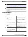
Configure the IKE Policy
6-1
6-3
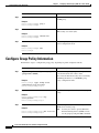
Configure Group Policy Information
6-4
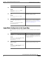
Apply Mode Configuration to the Crypto Map
Enable Policy Lookup
3-2
6-5
6-6
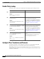
Configure IPsec Transforms and Protocols
6-6
Configure the IPsec Crypto Method and Parameters
6-7
Cisco Secure Router 520 Series Software Configuration Guide
iv
OL-14210-01
Contents
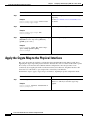
Apply the Crypto Map to the Physical Interface
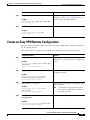
Create an Easy VPN Remote Configuration
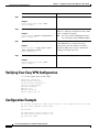
Verifying Your Easy VPN Configuration
Configuration Example
CHAPTER
7
6-8
6-9
6-10
6-10
Configuring VPNs Using an IPsec Tunnel and Generic Routing Encapsulation
7-1
Configure a VPN 7-2
Configure the IKE Policy 7-3
Configure Group Policy Information 7-4
Enable Policy Lookup 7-5
Configure IPsec Transforms and Protocols 7-5
Configure the IPsec Crypto Method and Parameters 7-6
Apply the Crypto Map to the Physical Interface 7-7
Configure a GRE Tunnel
Configuration Example
CHAPTER
8
7-8
7-9
Configuring a Simple Firewall
Configure Access Lists
8-1
8-3
Configure Inspection Rules
8-4
Apply Access Lists and Inspection Rules to Interfaces
Configuration Example
CHAPTER
9
8-5
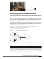
Configuring a Wireless LAN Connection
Configure the Root Radio Station
Configure Bridging on VLANs
PART
9-1
9-2
9-4
Configure Radio Station Subinterfaces
Configuration Example
8-4
9-5
9-6
Configuring Additional Features and Troubleshooting
3
CHAPTER
10
Additional Configuration Options
CHAPTER
11
Configuring Security Features
10-1
11-1
Authentication, Authorization, and Accounting
Configuring AutoSecure
11-1
11-2
Configuring Access Lists 11-2
Access Groups 11-3
Cisco Secure Router 520 Series Software Configuration Guide
OL-14210-01
v
Contents
Guidelines for Creating Access Groups
Configuring a CBAC Firewall
11-3
Configuring Cisco IOS Firewall IDS
Configuring VPNs
CHAPTER
12
Troubleshooting
Getting Started
11-3
11-4
11-4
12-1
12-1
Before Contacting Cisco or Your Reseller
ADSL Troubleshooting
12-1
12-2
ATM Troubleshooting Commands 12-2
ping atm interface Command 12-2
show interface Command 12-3
show atm interface Command 12-5
debug atm Commands 12-5
Guidelines for Using Debug Commands
debug atm errors Command 12-6
debug atm events Command 12-6
debug atm packet Command 12-7
Software Upgrade Methods
12-5
12-8
Recovering a Lost Password 12-9
Change the Configuration Register 12-9
Reset the Router 12-10
Reset the Password and Save Your Changes 12-11
Reset the Configuration Register Value 12-11
PART
Reference Information
4
APPENDIX
A
Cisco IOS Software Basic Skills
A-1
Configuring the Router from a PC
A-1
Understanding Command Modes
A-2
Getting Help
A-4
Enable Secret Passwords and Enable Passwords
Entering Global Configuration Mode
A-5
Using Commands A-5
Abbreviating Commands A-6
Undoing Commands A-6
Command-Line Error Messages
A-6
A-4
Cisco Secure Router 520 Series Software Configuration Guide
vi
OL-14210-01
Contents
Saving Configuration Changes
Summary
A-7
Where to Go Next
B
APPENDIX
Concepts
B-1
ADSL
B-1
Network Protocols
IP B-2
A-7
B-2
Routing Protocol Options
RIP B-2
B-2
PPP Authentication Protocols
PAP B-3
CHAP B-3
TACACS+
A-6
B-3
B-4
Network Interfaces B-4
Ethernet B-4
ATM for DSL B-4
PVC B-5
Dialer Interface B-5
NAT
B-5
Easy IP (Phase 1)
B-6
Easy IP (Phase 2)
B-6
QoS
B-7
IP Precedence B-7
PPP Fragmentation and Interleaving
CBWFQ B-8
RSVP B-8
Low Latency Queuing B-8
Access Lists
CHAPTER
C
ROM Monitor
B-7
B-9
C-1
Entering the ROM Monitor
ROM Monitor Commands
Command Descriptions
C-1
C-2
C-3
Disaster Recovery with TFTP Download C-3
TFTP Download Command Variables C-4
Required Variables C-4
Cisco Secure Router 520 Series Software Configuration Guide
OL-14210-01
vii
Contents
Optional Variables C-4
Using the TFTP Download Command
C-5
Configuration Register C-5
Changing the Configuration Register Manually C-6
Changing the Configuration Register Using Prompts C-6
Console Download C-7
Command Description
Error Reporting C-8
Debug Commands
APPENDIX
D
C-7
C-8
Exiting the ROM Monitor
C-9
Common Port Assignments
D-1
INDEX
Cisco Secure Router 520 Series Software Configuration Guide
viii
OL-14210-01
Preface
This preface describes the objectives, audience, organization, and conventions of this guide, and
describes related documents that have additional information. It contains the following sections:
•
Objective, page ix
•
Audience, page ix
•
Organization, page x
•
Conventions, page xi
•
Related Documentation, page xvi
•
Obtaining Documentation and Submitting a Service Request, page xvii
Objective
This guide provides an overview and explains how to install and connect the wireless and nonwireless
Cisco Secure Router 520 Series routers.
For warranty, service, and support information, see the “Cisco One-Year Limited Hardware Warranty
Terms” section in the Readme First for Cisco Secure Router 520 Series document that was shipped with
your router.
Audience
This guide is intended for network administrators whose backgrounds vary from having little or no
experience in configuring routers to having a high level of experience.
Cisco Secure Router 520 Series Software Configuration Guide
OL-14210-01
ix
Preface
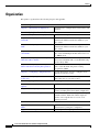
Organization
This guide is organized into the following chapters and appendix.
Part 1: Getting Started
Chapter 1, “Basic Router Configuration”
Describes how to configure basic router features and
interfaces.
Part 2: Configuring Your Router for Ethernet and DSL Access
Chapter 2, “Sample Network Deployments”
Provides a road map for Part 2.
Chapter 3, “Configuring PPP over Ethernet
with NAT”
Provides instructions on how to configure PPPoE
with Network Address Translation (NAT) on your
Cisco router.
Chapter 4, “Configuring PPP over ATM with
NAT”
Provides instructions on how to configure PPPoA
with Network Address Translation (NAT) on your
Cisco router.
Chapter 5, “Configuring a LAN with DHCP
and VLANs”
Provides instructions on how to configure your
Cisco router with multiple VLANs and to have it act
as a DHCP server.
Chapter 6, “Configuring a VPN Using Easy
VPN and an IPsec Tunnel”
Provides instructions on how to configure a virtual
private network (VPN) with a secure IP tunnel using
the Cisco Easy VPN.
Chapter 7, “Configuring VPNs Using an IPsec Provides instructions on how to configure a VPN
with a secure IP tunnel and generic routing
Tunnel and Generic Routing Encapsulation”
encapsulation (GRE).
Chapter 8, “Configuring a Simple Firewall”
Provides instructions on how to configure a basic
firewall on your Cisco router.
Chapter 9, “Configuring a Wireless LAN
Connection”
Provides instructions on how to configure a wireless
LAN connection on your Cisco router.
Part 3: Configuring Additional Features and Troubleshooting
Chapter 10, “Additional Configuration
Options”
Provides a road map for Part 3.
Chapter 11, “Configuring Security Features”
Explains basic configuration of Cisco IOS security
features, including firewall and VPN configuration.
Chapter 12, “Troubleshooting”
Provides information on identifying and solving
problems with the ADSL line and the telephone
interface. Also explains how to recover a lost
software password.
Part 4: Reference Information
Appendix A, “Cisco IOS Software Basic
Skills”
Explains what you need to know about Cisco IOS
software before you begin to configure it.
Appendix B, “Concepts”
Provides general concept explanations of features.
Cisco Secure Router 520 Series Software Configuration Guide
x
OL-14210-01
Preface
Appendix C, “ROM Monitor”
Describes the use of the ROM Monitor (ROMMON)
utility.
Appendix D, “Common Port Assignments”
Describes the currently assigned Transmission
Control Protocol (TCP) and User Datagram Protocol
(UDP) port numbers.
Conventions
This section describes the conventions used in this guide.
Note
Caution
Warning
Means reader take note. Notes contain helpful suggestions or references to additional information and
material.
This symbol means reader be careful. In this situation, you might do something that could result in
equipment damage or loss of data.
IMPORTANT SAFETY INSTRUCTIONS
This warning symbol means danger. You are in a situation that could cause bodily injury. Before you
work on any equipment, be aware of the hazards involved with electrical circuitry and be familiar
with standard practices for preventing accidents. Use the statement number provided at the end of
each warning to locate its translation in the translated safety warnings that accompanied this
device. Statement 1071
SAVE THESE INSTRUCTIONS
Waarschuwing
BELANGRIJKE VEILIGHEIDSINSTRUCTIES
Dit waarschuwingssymbool betekent gevaar. U verkeert in een situatie die lichamelijk letsel kan
veroorzaken. Voordat u aan enige apparatuur gaat werken, dient u zich bewust te zijn van de bij
elektrische schakelingen betrokken risico's en dient u op de hoogte te zijn van de standaard
praktijken om ongelukken te voorkomen. Gebruik het nummer van de verklaring onderaan de
waarschuwing als u een vertaling van de waarschuwing die bij het apparaat wordt geleverd, wilt
raadplegen.
BEWAAR DEZE INSTRUCTIES
Varoitus
TÄRKEITÄ TURVALLISUUSOHJEITA
Tämä varoitusmerkki merkitsee vaaraa. Tilanne voi aiheuttaa ruumiillisia vammoja. Ennen kuin
käsittelet laitteistoa, huomioi sähköpiirien käsittelemiseen liittyvät riskit ja tutustu
onnettomuuksien yleisiin ehkäisytapoihin. Turvallisuusvaroitusten käännökset löytyvät laitteen
mukana toimitettujen käännettyjen turvallisuusvaroitusten joukosta varoitusten lopussa näkyvien
lausuntonumeroiden avulla.
SÄILYTÄ NÄMÄ OHJEET
Cisco Secure Router 520 Series Software Configuration Guide
OL-14210-01
xi
Preface
Attention
IMPORTANTES INFORMATIONS DE SÉCURITÉ
Ce symbole d'avertissement indique un danger. Vous vous trouvez dans une situation pouvant
entraîner des blessures ou des dommages corporels. Avant de travailler sur un équipement, soyez
conscient des dangers liés aux circuits électriques et familiarisez-vous avec les procédures
couramment utilisées pour éviter les accidents. Pour prendre connaissance des traductions des
avertissements figurant dans les consignes de sécurité traduites qui accompagnent cet appareil,
référez-vous au numéro de l'instruction situé à la fin de chaque avertissement.
CONSERVEZ CES INFORMATIONS
Warnung
WICHTIGE SICHERHEITSHINWEISE
Dieses Warnsymbol bedeutet Gefahr. Sie befinden sich in einer Situation, die zu Verletzungen führen
kann. Machen Sie sich vor der Arbeit mit Geräten mit den Gefahren elektrischer Schaltungen und
den üblichen Verfahren zur Vorbeugung vor Unfällen vertraut. Suchen Sie mit der am Ende jeder
Warnung angegebenen Anweisungsnummer nach der jeweiligen Übersetzung in den übersetzten
Sicherheitshinweisen, die zusammen mit diesem Gerät ausgeliefert wurden.
BEWAHREN SIE DIESE HINWEISE GUT AUF.
Avvertenza
IMPORTANTI ISTRUZIONI SULLA SICUREZZA
Questo simbolo di avvertenza indica un pericolo. La situazione potrebbe causare infortuni alle
persone. Prima di intervenire su qualsiasi apparecchiatura, occorre essere al corrente dei pericoli
relativi ai circuiti elettrici e conoscere le procedure standard per la prevenzione di incidenti.
Utilizzare il numero di istruzione presente alla fine di ciascuna avvertenza per individuare le
traduzioni delle avvertenze riportate in questo documento.
CONSERVARE QUESTE ISTRUZIONI
Advarsel
VIKTIGE SIKKERHETSINSTRUKSJONER
Dette advarselssymbolet betyr fare. Du er i en situasjon som kan føre til skade på person. Før du
begynner å arbeide med noe av utstyret, må du være oppmerksom på farene forbundet med
elektriske kretser, og kjenne til standardprosedyrer for å forhindre ulykker. Bruk nummeret i slutten
av hver advarsel for å finne oversettelsen i de oversatte sikkerhetsadvarslene som fulgte med denne
enheten.
TA VARE PÅ DISSE INSTRUKSJONENE
Aviso
INSTRUÇÕES IMPORTANTES DE SEGURANÇA
Este símbolo de aviso significa perigo. Você está em uma situação que poderá ser causadora de
lesões corporais. Antes de iniciar a utilização de qualquer equipamento, tenha conhecimento dos
perigos envolvidos no manuseio de circuitos elétricos e familiarize-se com as práticas habituais de
prevenção de acidentes. Utilize o número da instrução fornecido ao final de cada aviso para
localizar sua tradução nos avisos de segurança traduzidos que acompanham este dispositivo.
GUARDE ESTAS INSTRUÇÕES
Cisco Secure Router 520 Series Software Configuration Guide
xii
OL-14210-01
Preface
¡Advertencia!
INSTRUCCIONES IMPORTANTES DE SEGURIDAD
Este símbolo de aviso indica peligro. Existe riesgo para su integridad física. Antes de manipular
cualquier equipo, considere los riesgos de la corriente eléctrica y familiarícese con los
procedimientos estándar de prevención de accidentes. Al final de cada advertencia encontrará el
número que le ayudará a encontrar el texto traducido en el apartado de traducciones que acompaña
a este dispositivo.
GUARDE ESTAS INSTRUCCIONES
Varning!
VIKTIGA SÄKERHETSANVISNINGAR
Denna varningssignal signalerar fara. Du befinner dig i en situation som kan leda till personskada.
Innan du utför arbete på någon utrustning måste du vara medveten om farorna med elkretsar och
känna till vanliga förfaranden för att förebygga olyckor. Använd det nummer som finns i slutet av
varje varning för att hitta dess översättning i de översatta säkerhetsvarningar som medföljer denna
anordning.
SPARA DESSA ANVISNINGAR
Cisco Secure Router 520 Series Software Configuration Guide
OL-14210-01
xiii
Preface
Aviso
INSTRUÇÕES IMPORTANTES DE SEGURANÇA
Este símbolo de aviso significa perigo. Você se encontra em uma situação em que há risco de lesões
corporais. Antes de trabalhar com qualquer equipamento, esteja ciente dos riscos que envolvem os
circuitos elétricos e familiarize-se com as práticas padrão de prevenção de acidentes. Use o
número da declaração fornecido ao final de cada aviso para localizar sua tradução nos avisos de
segurança traduzidos que acompanham o dispositivo.
GUARDE ESTAS INSTRUÇÕES
Advarsel
VIGTIGE SIKKERHEDSANVISNINGER
Dette advarselssymbol betyder fare. Du befinder dig i en situation med risiko for
legemesbeskadigelse. Før du begynder arbejde på udstyr, skal du være opmærksom på de
involverede risici, der er ved elektriske kredsløb, og du skal sætte dig ind i standardprocedurer til
undgåelse af ulykker. Brug erklæringsnummeret efter hver advarsel for at finde oversættelsen i de
oversatte advarsler, der fulgte med denne enhed.
GEM DISSE ANVISNINGER
Cisco Secure Router 520 Series Software Configuration Guide
xiv
OL-14210-01
Preface
Cisco Secure Router 520 Series Software Configuration Guide
OL-14210-01
xv
Preface
Related Documentation
The Cisco Secure Router 520 Series product is shipped with a minimal set of printed documentation.
Additional product documentation is available on Cisco.com.
In addition to the Cisco Secure Router 520 Series Software Configuration Guide (this document), the
Cisco Secure Router 520 Series documentation set includes the following documents.
The following documentation is shipped with the product:
•
For warranty, service, and support information, see the Readme First for Cisco Secure Router 520
Series document.
•
Cisco Regulatory Compliance and Safety Information Roadmap
The following Cisco Secure Router 520 Series product documentation is available on Cisco.com:
•
Cisco Secure Router 520 Series Hardware Installation Guide
http://www.cisco.com/en/US/docs/routers/access/500/520/hardware/installation/guide/SR_520_HI
guide.html
•
Regulatory Compliance and Safety Information for Cisco Secure Router 500 Series
http://www.cisco.com/en/US/docs/routers/access/500/520/rcsi/500_rcsi.html
Cisco Secure Router 520 Series Software Configuration Guide
xvi
OL-14210-01
Preface
Obtaining Documentation and Submitting a Service Request
For information on obtaining documentation, submitting a service request, and gathering additional
information, see the monthly What’s New in Cisco Product Documentation, which also lists all new and
revised Cisco technical documentation, at:
http://www.cisco.com/en/US/docs/general/whatsnew/whatsnew.html
Subscribe to the What’s New in Cisco Product Documentation as a Really Simple Syndication (RSS) feed
and set content to be delivered directly to your desktop using a reader application. The RSS feeds are a free
service and Cisco currently supports RSS version 2.0.
Cisco Secure Router 520 Series Software Configuration Guide
OL-14210-01
xvii
Preface
Cisco Secure Router 520 Series Software Configuration Guide
xviii
OL-14210-01
PA R T
1
Getting Started
CH A P T E R
1
Basic Router Configuration
The Cisco Secure Router 520 Series routers are designed for small businesses with up to 50 users and
teleworkers who want secure connectivity to corporate LANs and to the Internet. These routers provide
advanced security features that include secure Virtual Private Network (VPN) access and comprehensive
threat defense with Cisco IOS Firewall, Intrusion Prevention Solution (IPS), and URL filtering. The
Cisco Secure Router 520 Series routers also provide dynamic routing and advanced quality of service
(QoS) features.
The Cisco Secure Router 520 Series routers complement the Cisco Unified Communications 500 Series
router and the Cisco Smart Business Communications System (SBCS) portfolio. As part of the SBCS
portfolio, the Cisco Secure Router 520 Series routers deliver a common user experience through
integration with the Cisco Configuration Assistant, Cisco Smart Assist, Cisco Monitor Manager, and
Cisco Monitor Director.
This chapter provides procedures for configuring the basic parameters of your Cisco router, including
global parameter settings, routing protocols, interfaces, and command-line access using the CLI. It also
describes the default configuration at startup.
Note
Individual router routers may not support every feature described throughout this guide. Features not
supported by a particular router are indicated whenever possible.
This chapter contains the following sections:
•
Viewing the Default Configuration
•
Information Needed for Customizing the Default Parameters
•
Interface Port Labels
•
Configuring Basic Parameters
•
Configuring Static Routes
•
Configuring Dynamic Routes
Each section includes a configuration example and verification steps, as available.
For complete information on how to access global configuration mode, see the “Entering Global
Configuration Mode” section in Appendix A, “Cisco IOS Basic Skills.” For more information on the
commands used in the following tables, see the Cisco IOS Release 12.3 documentation set.
Cisco Secure Router 520 Series Software Configuration Guide
OL-14210-01
1-1
Chapter 1
Basic Router Configuration
Viewing the Default Configuration
Viewing the Default Configuration
When the router first boots up, some basic configuration has already been performed. All of the LAN
and WAN interfaces have been created, console and VTY ports are configured, and the inside interface
for Network Address Translation has been assigned.
To view the default configuration, follow these steps:
Step 1
Use the default username cisco and the default password cisco to enter the privileged EXEC mode.
Step 2
Use the show running-config command to view the initial configuration.
Information Needed for Customizing the Default Parameters
You need to gather some or all of the following information, depending on your planned network
scenario, prior to configuring your network.
•
If you are setting up an Internet connection, gather the following information:
– Point-to-Point Protocol (PPP) client name that is assigned as your login name
– PPP authentication type: Challenge Handshake Authentication Protocol (CHAP) or Password
Authentication Protocol (PAP)
– PPP password to access your Internet service provider (ISP) account
– DNS server IP address and default gateways
•
If you are setting up a connection to a corporate network, you and the network administrator must
generate and share the following information for the WAN interfaces of the routers:
– PPP authentication type: CHAP or PAP
– PPP client name to access the router
– PPP password to access the router
•
If you are setting up IP routing:
– Generate the addressing scheme for your IP network.
– Determine the IP routing parameter information, including IP address, and ATM permanent
virtual circuits (PVCs). These PVC parameters are typically virtual path identifier (VPI), virtual
circuit identifier (VCI), and traffic shaping parameters.
– Determine the number of PVCs that your service provider has given you, along with their VPIs
and VCIs.
– For each PVC determine the type of AAL5 encapsulation supported. It can be one of the
following:
AAL5SNAP—This can be either routed RFC 1483 or bridged RFC 1483. For routed RFC 1483,
the service provider must provide you with a static IP address. For bridged RFC 1483, you may
use DHCP to obtain your IP address, or you may obtain a static IP address from your service
provider.
AAL5MUX PPP—With this type of encapsulation, you need to determine the PPP-related
configuration items.
•
If you plan to connect over an ADSL line:
Cisco Secure Router 520 Series Software Configuration Guide
1-2
OL-14210-01
Chapter 1
Basic Router Configuration
Interface Port Labels
– Order the appropriate line from your public telephone service provider. Ensure that the ADSL
signaling type is DMT (also called ANSI T1.413) or DMT Issue 2.
Once you have collected the appropriate information, you can perform a full configuration on
your router, beginning with the tasks in the “Configuring Basic Parameters” section.
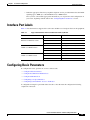
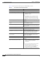
Interface Port Labels
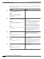
Table 1-1 lists the interfaces supported for each router and their associated port labels on the equipment.
Table 1-1
Supported Interfaces and Associated Port Labels by Router
Router
Interface
Port Label
Cisco Secure Router 520
Ethernet-to-Ethernet routers
Fast Ethernet LAN
FE0–FE3
Fast Ethernet WAN
FE4
Wireless LAN
None (antenna is not labeled)
Fast Ethernet LAN
LAN (top), FE0–FE3 (bottom)
ATM WAN
ADSLoPOTS
Wireless LAN
None (antenna is not labeled)
Fast Ethernet LAN
LAN (top), FE0–FE3 (bottom)
ATM WAN
ADSLoISDN
Wireless LAN
None (antenna is not labeled)
Cisco Secure Router 520
ADSL-over-POTS routers
Cisco Secure Router 520
ADSL-over-ISDN routers
Configuring Basic Parameters
To configure the router, perform one or more of these tasks:
•
Configure Global Parameters
•
Configure Fast Ethernet LAN Interfaces
•
Configure WAN Interfaces
•
Configuring a Loopback Interface
•
Configuring Command-Line Access to the Router
A configuration example is presented with each task to show the network configuration following
completion of that task.
Cisco Secure Router 520 Series Software Configuration Guide
OL-14210-01
1-3
Chapter 1
Basic Router Configuration
Configuring Basic Parameters
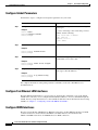
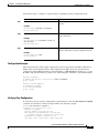
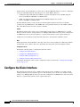
Configure Global Parameters
Perform these steps to configure selected global parameters for your router:
Step 1
Command
Purpose
configure terminal
Enters global configuration mode, when using the
console port.
Example:
If you are connecting to the router using a remote
terminal, use the following:
Router> enable
Router# configure terminal
Router(config)#
Step 2
hostname name
telnet router name or address
Login: login id
Password: *********
Router> enable
Specifies the name for the router.
Example:
Router(config)# hostname Router
Router(config)#
Step 3
enable secret password
Specifies an encrypted password to prevent
unauthorized access to the router.
Example:
Router(config)# enable secret cr1ny5ho
Router(config)#
Step 4
no ip domain-lookup
Disables the router from translating unfamiliar
words (typos) into IP addresses.
Example:
Router(config)# no ip domain-lookup
Router(config)#
For complete information on the global parameter commands, see the Cisco IOS Release 12.3
documentation set.
Configure Fast Ethernet LAN Interfaces
The Fast Ethernet LAN interfaces on your router are automatically configured as part of the default
VLAN and as such, they are not configured with individual addresses. Access is afforded through the
VLAN. You may assign the interfaces to other VLANs if desired. For more information about creating
VLANs, see Chapter 5, “Configuring a LAN with DHCP and VLANs.”
Configure WAN Interfaces
The Cisco Secure Router 520 Ethernet-to-Ethernet routers have one Fast Ethernet interface for WAN
connection. The Cisco Secure Router 520 ADSL-over-POTS and Cisco Secure Router 520
ADSL-over-ISDN routers have one ATM interface for WAN connection.
Cisco Secure Router 520 Series Software Configuration Guide
1-4
OL-14210-01
Chapter 1
Basic Router Configuration
Configuring Basic Parameters
Based on the router you have, configure the WAN interface(s) by using one of the following procedures:
•
Configure the Fast Ethernet WAN Interface
•
Configure the ATM WAN Interface
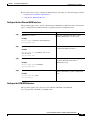
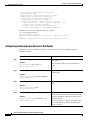
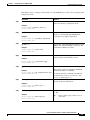
Configure the Fast Ethernet WAN Interface
This procedure applies only to the Cisco Secure Router 520 Ethernet-to-Ethernet routers. Perform these
steps to configure the Fast Ethernet interface, beginning in global configuration mode:
Step 1
Command
Purpose
interface type number
Enters the configuration mode for a Fast
Ethernet WAN interface on the router.
Example:
Router(config)# interface fastethernet 4
Router(config-if)#
Step 2
ip address ip-address mask
Sets the IP address and subnet mask for the
specified Fast Ethernet interface.
Example:
Router(config-if)# ip address 192.1.12.2
255.255.255.0
Router(config-if)#
Step 3
no shutdown
Example:
Enables the Ethernet interface, changing its
state from administratively down to
administratively up.
Router(config-if)# no shutdown
Router(config-if)#
Step 4
exit
Example:
Exits configuration mode for the Fast Ethernet
interface and returns to global configuration
mode.
Router(config-if)# exit
Router(config)#
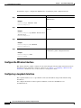
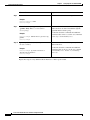
Configure the ATM WAN Interface
This procedure applies only to the Cisco Secure Router 520 ADSL-over-POTS and
Cisco Secure Router 520 ADSL-over-ISDN routers.
Cisco Secure Router 520 Series Software Configuration Guide
OL-14210-01
1-5
Chapter 1
Basic Router Configuration
Configuring Basic Parameters
Perform these steps to configure the ATM interface, beginning in global configuration mode:
Step 1
Command
Purpose
interface type number
Identifies and enters the configuration mode for an
ATM interface.
Example:
Router(config)# interface atm0
Router(config-if)#
Step 2
ip address ip-address mask
Sets the IP address and subnet mask for the ATM
interface.
Example:
Router(config-if)# ip address 200.200.100.1
255.255.255.0
Router(config-if)#
Step 3
no shutdown
Enables the ATM 0 interface.
Example:
Router(config-if)# no shutdown
Router(config-if)#
Step 4
exit
Exits configuration mode for the ATM interface
and returns to global configuration mode.
Example:
Router(config-if)# exit
Router(config)#
Configure the Wireless Interface
The wireless interface enables connection to the router through a wireless LAN connection. For more
information about configuring a wireless connection, see Chapter 9, “Configuring a Wireless LAN
Connection,” and the Cisco Access Router Wireless Configuration Guide.
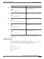
Configuring a Loopback Interface
The loopback interface acts as a placeholder for the static IP address and provides default routing
information.
For complete information on the loopback commands, see the Cisco IOS Release 12.3
documentation set.
Cisco Secure Router 520 Series Software Configuration Guide
1-6
OL-14210-01
Chapter 1
Basic Router Configuration
Configuring Basic Parameters
Perform these steps to configure a loopback interface, beginning in global configuration mode:
Step 1
Command
Purpose
interface type number
Enters configuration mode for the loopback
interface.
Example:
Router(config)# interface Loopback 0
Router(config-if)#
Step 2
ip address ip-address mask
Sets the IP address and subnet mask for the
loopback interface.
Example:
Router(config-if)# ip address 10.108.1.1
255.255.255.0
Router(config-if)#
Step 3
exit
Exits configuration mode for the loopback
interface and returns to global configuration mode.
Example:
Router(config-if)# exit
Router(config)#
Configuration Example
The loopback interface in this sample configuration is used to support Network Address Translation
(NAT) on the virtual-template interface. This configuration example shows the loopback interface
configured on the Fast Ethernet interface with an IP address of 200.200.100.1/24, which acts as a static
IP address. The loopback interface points back to virtual-template1, which has a negotiated IP address.
!
interface loopback 0
ip address 200.200.100.1 255.255.255.0 (static IP address)
ip nat outside
!
interface Virtual-Template1
ip unnumbered loopback0
no ip directed-broadcast
ip nat outside
!
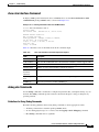
Verifying Your Configuration
To verify that you have properly configured the loopback interface, enter the show interface loopback
command. You should see verification output similar to the following example.
Router# show interface loopback 0
Loopback0 is up, line protocol is up
Hardware is Loopback
Internet address is 200.200.100.1/24
MTU 1514 bytes, BW 8000000 Kbit, DLY 5000 usec,
reliability 255/255, txload 1/255, rxload 1/255
Encapsulation LOOPBACK, loopback not set
Last input never, output never, output hang never
Cisco Secure Router 520 Series Software Configuration Guide
OL-14210-01
1-7
Chapter 1
Basic Router Configuration
Configuring Basic Parameters
Last clearing of "show interface" counters never
Queuing strategy: fifo
Output queue 0/0, 0 drops; input queue 0/75, 0 drops
5 minute input rate 0 bits/sec, 0 packets/sec
5 minute output rate 0 bits/sec, 0 packets/sec
0 packets input, 0 bytes, 0 no buffer
Received 0 broadcasts, 0 runts, 0 giants, 0 throttles
0 input errors, 0 CRC, 0 frame, 0 overrun, 0 ignored, 0 abort
0 packets output, 0 bytes, 0 underruns
0 output errors, 0 collisions, 0 interface resets
0 output buffer failures, 0 output buffers swapped out
Another way to verify the loopback interface is to ping it:
Router# ping 200.200.100.1
Type escape sequence to abort.
Sending 5, 100-byte ICMP Echos to 200.200.100.1, timeout is 2 seconds:
!!!!!
Success rate is 100 percent (5/5), round-trip min/avg/max = 1/2/4 ms
Configuring Command-Line Access to the Router
Perform these steps to configure parameters to control access to the router, beginning in global
configuration mode:
Step 1
Command
Purpose
line [aux | console | tty | vty] line-number
Enters line configuration mode, and specifies the
type of line.
Example:
This example specifies a console terminal for
access.
Router(config)# line console 0
Router(config-line)#
Step 2
password password
Specifies a unique password for the console
terminal line.
Example:
Router(config-line)# password 5dr4Hepw3
Router(config-line)#
Step 3
login
Enables password checking at terminal session
login.
Example:
Router(config-line)# login
Router(config-line)#
Step 4
exec-timeout minutes [seconds]
Example:
Router(config-line)# exec-timeout 5 30
Router(config-line)#
Sets the interval that the EXEC command
interpreter waits until user input is detected. The
default is 10 minutes. Optionally, add seconds to
the interval value.
This example shows a timeout of 5 minutes and
30 seconds. Entering a timeout of 0 0 specifies
never to time out.
Cisco Secure Router 520 Series Software Configuration Guide
1-8
OL-14210-01
Chapter 1
Basic Router Configuration
Configuring Basic Parameters
Step 5
Command
Purpose
exit
Exits line configuration mode, and returns to
global configuration mode.
Example:
Router(config-line)# exit
Router (config)#
Step 6
line [aux | console | tty | vty] line-number
Specifies a virtual terminal for remote console
access.
Example:
Router(config)# line vty 0 4
Router(config-line)#
Step 7
password password
Specifies a unique password for the virtual
terminal line.
Example:
Router(config-line)# password aldf2ad1
Router(config-line)#
Step 8
login
Enables password checking at the virtual terminal
session login.
Example:
Router(config-line)# login
Router(config-line)#
Step 9
end
Exits line configuration mode, and returns to
privileged EXEC mode.
Example:
Router(config-line)# end
Router#
For complete information about the command line commands, see the Cisco IOS Release 12.3
documentation set.
Configuration Example
The following configuration shows the command-line access commands.
You do not need to input the commands marked “default.” These commands appear automatically in the
configuration file generated when you use the show running-config command.
!
line con 0
exec-timeout 10 0
password 4youreyesonly
login
transport input none (default)
stopbits 1 (default)
line vty 0 4
password secret
login
!
Cisco Secure Router 520 Series Software Configuration Guide
OL-14210-01
1-9
Chapter 1
Basic Router Configuration
Configuring Static Routes
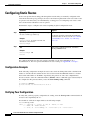
Configuring Static Routes
Static routes provide fixed routing paths through the network. They are manually configured on the
router. If the network topology changes, the static route must be updated with a new route. Static routes
are private routes unless they are redistributed by a routing protocol. Configuring static routes on the
Cisco Secure Router 520 Series router is optional.
Perform these steps to configure static routes, beginning in global configuration mode:
Step 1
Command
Purpose
ip route prefix mask {ip-address | interface-type
interface-number [ip-address]}
Specifies the static route for the IP packets.
Example:
Router(config)# ip route 192.168.0.0
255.255.0.0 10.10.10.2
Router(config)#
Step 2
end
For details about this command and additional
parameters that can be set, see the Cisco IOS IP
Command Reference, Volume 2 of 4: Routing
Protocols.
Exits router configuration mode, and enters
privileged EXEC mode.
Example:
Router(config)# end
Router#
For complete information on the static routing commands, see the Cisco IOS Release 12.3
documentation set. For more general information on static routing, see Appendix B, “Concepts.”
Configuration Example
In the following configuration example, the static route sends out all IP packets with a destination IP
address of 192.168.1.0 and a subnet mask of 255.255.255.0 on the Fast Ethernet interface to another
device with an IP address of 10.10.10.2. Specifically, the packets are sent to the configured PVC.
You do not need to enter the commands marked “(default).” These commands appear automatically in
the configuration file generated when you use the show running-config command.
!
ip classless (default)
ip route 192.168.1.0 255.255.255.0 10.10.10.2
!
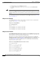
Verifying Your Configuration
To verify that you have properly configured static routing, enter the show ip route command and look
for static routes signified by the “S.”
You should see verification output similar to the following example.
Router# show ip route
Codes: C - connected, S - static, R - RIP, M - mobile, B - BGP
D - EIGRP, EX - EIGRP external,
i - IS-IS, su - IS-IS summary, L1 - IS-IS level-1, L2 - IS-IS level-2
Cisco Secure Router 520 Series Software Configuration Guide
1-10
OL-14210-01
Chapter 1
Basic Router Configuration
Configuring Dynamic Routes
ia - IS-IS inter area, * - candidate default, U - per-user static route
o - ODR, P - periodic downloaded static route
Gateway of last resort is not set
10.0.0.0/24 is subnetted, 1 subnets
C
10.108.1.0 is directly connected, Loopback0
S* 0.0.0.0/0 is directly connected, FastEthernet0
Configuring Dynamic Routes
In dynamic routing, the network protocol adjusts the path automatically, based on network traffic or
topology. Changes in dynamic routes are shared with other routers in the network.
The Cisco routers can use IP routing protocols, such as Routing Information Protocol (RIP), to learn
routes dynamically. You can configure either of these routing protocols on your router.
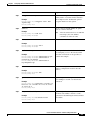
Configuring RIP
Perform these steps to configure the RIP routing protocol on the router, beginning in global
configuration mode:
Step 1
Command
Task
router rip
Enters router configuration mode, and enables RIP
on the router.
Example:
Router# configure terminal
Router(config)# router rip
Router(config-router)#
Step 2
version {1 | 2}
Specifies use of RIP version 1 or 2.
Example:
Router(config-router)# version 2
Router(config-router)#
Step 3
network ip-address
Specifies a list of networks on which RIP is to be
applied, using the address of the network of
directly connected networks.
Example:
Router(config-router)# network 192.168.1.1
Router(config-router)# network 10.10.7.1
Router(config-router)#
Cisco Secure Router 520 Series Software Configuration Guide
OL-14210-01
1-11
Chapter 1
Basic Router Configuration
Configuring Dynamic Routes
Step 4
Command
Task
no auto-summary
Disables automatic summarization of subnet routes
into network-level routes. This allows subprefix
routing information to pass across classful network
boundaries.
Example:
Router(config-router)# no auto-summary
Router(config-router)#
Step 5
end
Exits router configuration mode, and enters
privileged EXEC mode.
Example:
Router(config-router)# end
Router#
For complete information on the dynamic routing commands, see the Cisco IOS Release 12.3
documentation set. For more general information on RIP, see Appendix B, “Concepts.”
Configuration Example
The following configuration example shows RIP version 2 enabled in IP network 10.0.0.0 and
192.168.1.0.
Execute the show running-config command from privileged EXEC mode to see this configuration.
!
router rip
version 2
network 10.0.0.0
network 192.168.1.0
no auto-summary
!
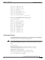
Verifying Your Configuration
To verify that you have properly configured RIP, enter the show ip route command and look for RIP
routes signified by “R.” You should see verification output like the example shown below.
Router# show ip route
Codes: C - connected, S - static, R - RIP, M - mobile, B - BGP
D - EIGRP, EX - EIGRP external,
i - IS-IS, su - IS-IS summary, L1 - IS-IS level-1, L2 - IS-IS level-2
ia - IS-IS inter area, * - candidate default, U - per-user static route
o - ODR, P - periodic downloaded static route
Gateway of last resort is not set
C
R
10.0.0.0/24 is subnetted, 1 subnets
10.108.1.0 is directly connected, Loopback0
3.0.0.0/8 [120/1] via 2.2.2.1, 00:00:02, Ethernet0/0
Cisco Secure Router 520 Series Software Configuration Guide
1-12
OL-14210-01
PA R T
2
Configuring Your Router for Ethernet and
DSL Access
CH A P T E R
2
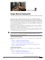
Sample Network Deployments
This part of the software configuration guide presents a variety of possible Ethernet and Digital
Subscriber Line (DSL)—based network configurations using the Cisco Secure Router 520 Series router.
Each scenario is described with a network topology, a step-by-step procedure that is used to implement
the network configuration, and a configuration example that shows the results of the configuration. The
Cisco Secure Router 520 Ethernet-to-Ethernet routers can be used in the Ethernet-based scenarios and
the Cisco Secure Router 520 ADSL-over-POTS and Cisco Secure Router 520 ADSL-over-ISDN routers
can be used in the DSL-based scenarios.
The first network scenario provides a simple network configuration: point-to-point protocol (PPP) over
the WAN interface with Network Address Translation (NAT). Each successive scenario builds on the
previous scenario by configuring another key feature.
The scenarios do not address all of the possible network needs; instead, they provide models on which
you can pattern your network. You can choose not to use features presented in the examples, or you can
add or substitute features that better suit your needs.
Note
To verify that a specific feature is compatible with your router, you can use the Software Advisor tool.
You can access this tool at www.cisco.com > Technical Support & Documentation > Tools &
Resources with your Cisco username and password.
For Ethernet-Based Network Deployments
Use the following configuration examples to assist you in configuring your router for Ethernet-based
networks.
•
Chapter 3, “Configuring PPP over Ethernet with NAT”
•
Chapter 5, “Configuring a LAN with DHCP and VLANs”
•
Chapter 6, “Configuring a VPN Using Easy VPN and an IPsec Tunnel”
•
Chapter 7, “Configuring VPNs Using an IPsec Tunnel and Generic Routing Encapsulation”
•
Chapter 8, “Configuring a Simple Firewall”
For DSL-Based Network Deployments
Use the following configuration examples to assist you in configuring your router for DSL-based
networks.
•
Chapter 4, “Configuring PPP over ATM with NAT”
•
Chapter 5, “Configuring a LAN with DHCP and VLANs”
•
Chapter 6, “Configuring a VPN Using Easy VPN and an IPsec Tunnel”
Cisco Secure Router 520 Series Software Configuration Guide
OL-14210-01
2-1
Chapter 2
Sample Network Deployments
•
Chapter 7, “Configuring VPNs Using an IPsec Tunnel and Generic Routing Encapsulation”
•
Chapter 8, “Configuring a Simple Firewall”
Cisco Secure Router 520 Series Software Configuration Guide
2-2
OL-14210-01
CH A P T E R
3
Configuring PPP over Ethernet with NAT
The Cisco Secure Router 520 Ethernet-to-Ethernet routers support Point-to-Point Protocol over Ethernet
(PPPoE) clients and network address translation (NAT).
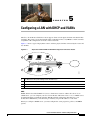
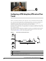
Multiple PCs can be connected to the LAN behind the router. Before the traffic from these PCs is sent
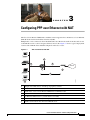
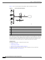
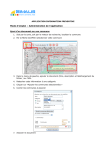
to the PPPoE session, it can be encrypted, filtered, and so forth. Figure 3-1 shows a typical deployment
scenario with a PPPoE client and NAT configured on the Cisco router.
Figure 3-1
PPP over Ethernet with NAT
4
5
2
Internet
3
6
121753
7
1
1
Multiple networked devices—Desktops, laptop PCs, switches
2
Fast Ethernet LAN interface (inside interface for NAT)
3
PPPoE client—Cisco Secure Router 520 Ethernet-to-Ethernet router
4
Point at which NAT occurs
5
Fast Ethernet WAN interface (outside interface for NAT)
6
Cable modem or other server (for example, a Cisco 6400 server) that is connected to the Internet
7
PPPoE session between the client and a PPPoE server
Cisco Secure Router 520 Series Software Configuration Guide
OL-14210-01
3-1
Chapter 3
Configuring PPP over Ethernet with NAT
Configure the Virtual Private Dialup Network Group Number
PPPoE
The PPPoE Client feature on the router provides PPPoE client support on Ethernet interfaces. A dialer
interface must be used for cloning virtual access. Multiple PPPoE client sessions can be configured on
an Ethernet interface, but each session must use a separate dialer interface and a separate dialer pool.
A PPPoE session is initiated on the client side by the Cisco Secure Router 520 Ethernet-to-Ethernet
routers. An established PPPoE client session can be terminated in one of two ways:
•
By entering the clear vpdn tunnel pppoe command. The PPPoE client session terminates, and the
PPPoE client immediately tries to reestablish the session. This also occurs if the session has a
timeout.
•
By entering the no pppoe-client dial-pool number command to clear the session. The PPPoE client
does not attempt to reestablish the session.
NAT
NAT (represented as the dashed line at the edge of the Cisco router) signifies two addressing domains
and the inside source address. The source list defines how the packet travels through the network.
Configuration Tasks
Perform the following tasks to configure this network scenario:
•
Configure the Virtual Private Dialup Network Group Number
•
Configure the Fast Ethernet WAN Interfaces
•
Configure the Dialer Interface
•
Configure Network Address Translation
An example showing the results of these configuration tasks is shown in the “Configuration Example”
section on page 3-8.
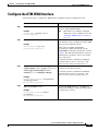
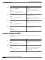
Configure the Virtual Private Dialup Network Group Number
Configuring a virtual private dialup network (VPDN) enables multiple clients to communicate through
the router by way of a single IP address.
Complete the following steps to configure a VPDN, starting from the global configuration mode. See the
“Configure Global Parameters” section on page 1-4 for details about entering this mode.
Step 1
Command or Action
Purpose
vpdn enable
Enables VPDN on the router.
Example:
Router(config)# vpdn enable
Router(config)#
Step 2
vpdn-group name
Creates and associates a VPDN group with a
customer or VPDN profile.
Example:
Router(config)# vpdn-group 1
Router(config-vpdn)#
Cisco Secure Router 520 Series Software Configuration Guide
3-2
OL-14210-01
Chapter 3
Configuring PPP over Ethernet with NAT
Configure the Fast Ethernet WAN Interfaces
Step 3
Command or Action
Purpose
request-dialin
Creates a request-dialin VPDN subgroup,
indicating the dialing direction, and initiates the
tunnel.
Example:
Router(config-vpdn)# request-dialin
Router(config-vpdn-req-in)#
Step 4
protocol {l2tp | pppoe}
Specifies the type of sessions the VPDN subgroup
can establish.
Example:
Router(config-vpdn-req-in)# protocol pppoe
Router(config-vpdn-req-in)#
Step 5
exit
Exits request-dialin VPDN group configuration.
Example:
Router(config-vpdn-req-in)# exit
Router(config-vpdn)#
Step 6
exit
Exits VPDN configuration, returning to global
configuration mode.
Example:
Router(config-vpdn)# exit
Router(config)#
Configure the Fast Ethernet WAN Interfaces
In this scenario, the PPPoE client (your Cisco router) communicates over a 10/100 Mbps-Ethernet
interface on both the inside and the outside.
Perform these steps to configure the Fast Ethernet WAN interfaces, starting in global configuration
mode:
Step 1
Command
Purpose
interface type number
Enters interface configuration mode for a
Fast Ethernet WAN interface.
Example:
Router(config)# interface fastethernet 4
Router(config-if)#
Step 2
pppoe-client dial-pool-number number
Configures the PPPoE client and specifies the
dialer interface to use for cloning.
Example:
Router(config-if)# pppoe-client
dial-pool-number 1
Router(config-if)#
Cisco Secure Router 520 Series Software Configuration Guide
OL-14210-01
3-3
Chapter 3
Configuring PPP over Ethernet with NAT
Configure the Dialer Interface
Step 3
Command
Purpose
no shutdown
Enables the Fast Ethernet interface and the
configuration changes just made to it.
Example:
Router(config-if)# no shutdown
Router(config-if)#
Step 4
exit
Example:
Exits configuration mode for the Fast Ethernet
interface and returns to global configuration
mode.
Router(config-if)# exit
Router(config)#
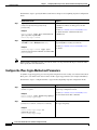
Configure the Dialer Interface
The dialer interface indicates how to handle traffic from the clients, including, for example, default
routing information, the encapsulation protocol, and the dialer pool to use. The dialer interface is also
used for cloning virtual access. Multiple PPPoE client sessions can be configured on a Fast Ethernet
interface, but each session must use a separate dialer interface and a separate dialer pool.
Complete the following steps to configure a dialer interface for one of the Fast Ethernet LAN interfaces
on the router, starting in global configuration mode:
Step 1
Command
Purpose
interface dialer dialer-rotary-group-number
Creates a dialer interface (numbered 0 to 255), and
enters interface configuration mode.
Example:
Router(config)# interface dialer 0
Router(config-if)#
Step 2
ip address negotiated
Example:
Specifies that the IP address for the interface is
obtained through PPP/IPCP (IP Control Protocol)
address negotiation.
Router(config-if)# ip address negotiated
Router(config-if)#
Step 3
ip mtu bytes
Example:
Sets the size of the IP maximum transmission unit
(MTU). The default minimum is 128 bytes. The
maximum for Ethernet is 1492 bytes.
Router(config-if)# ip mtu 1492
Router(config-if)#
Step 4
encapsulation encapsulation-type
Sets the encapsulation type to PPP for the data
packets being transmitted and received.
Example:
Router(config-if)# encapsulation ppp
Router(config-if)#
Cisco Secure Router 520 Series Software Configuration Guide
3-4
OL-14210-01
Chapter 3
Configuring PPP over Ethernet with NAT
Configure Network Address Translation
Step 5
Command
Purpose
ppp authentication {protocol1 [protocol2...]}
Sets the PPP authentication method to Challenge
Handshake Authentication Protocol (CHAP).
Example:
For details about this command and additional
parameters that can be set, see the Cisco IOS
Security Command Reference.
Router(config-if)# ppp authentication chap
Router(config-if)#
Step 6
dialer pool number
Specifies the dialer pool to use to connect to a
specific destination subnetwork.
Example:
Router(config-if)# dialer pool 1
Router(config-if)#
Step 7
dialer-group group-number
Assigns the dialer interface to a dialer group
(1–10).
Example:
Tip
Router(config-if)# dialer-group 1
Router(config-if)#
Step 8
exit
Using a dialer group controls access to
your router.
Exits the dialer 0 interface configuration.
Example:
Router(config-if)# exit
Router(config)#
Step 9
dialer-list dialer-group protocol protocol-name
{permit | deny | list access-list-number |
access-group}
Creates a dialer list and associates a dial group
with it. Packets are then forwarded through the
specified interface dialer group.
Example:
For details about this command and additional
parameters that can be set, see the Cisco IOS Dial
Technologies Command Reference.
Router(config)# dialer-list 1 protocol ip
permit
Router(config)#
Step 10
ip route prefix mask {interface-type
interface-number}
Example:
Router(config)# ip route 10.10.25.2
255.255.255.255 dialer 0
Router(config)#
Sets the IP route for the default gateway for the
dialer 0 interface.
For details about this command and additional
parameters that can be set, see the Cisco IOS IP
Command Reference, Volume 2; Routing
Protocols.
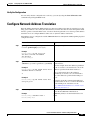
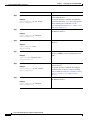
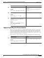
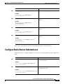
Configure Network Address Translation
Network Address Translation (NAT) translates packets from addresses that match a standard access list,
using global addresses allocated by the dialer interface. Packets that enter the router through the inside
interface, packets sourced from the router, or both are checked against the access list for possible address
translation. You can configure NAT for either static or dynamic address translations.
Cisco Secure Router 520 Series Software Configuration Guide
OL-14210-01
3-5
Chapter 3
Configuring PPP over Ethernet with NAT
Configure Network Address Translation
Perform these steps to configure the outside Fast Ethernet WAN interface with dynamic NAT, beginning
in global configuration mode:
Step 1
Command
Purpose
ip nat pool name start-ip end-ip {netmask
netmask | prefix-length prefix-length}
Creates pool of global IP addresses for NAT.
Example:
Router(config)# ip nat pool pool1
192.168.1.0 192.168.2.0 netmask
255.255.252.0
Router(config)#
Step 2
ip nat inside source {list access-list-number}
{interface type number | pool name} [overload]
Enables dynamic translation of addresses on the
inside interface.
Example 1:
The first example shows the addresses permitted
by the access list 1 to be translated to one of the
addresses specified in the dialer interface 0.
Router(config)# ip nat inside source list 1
interface dialer 0 overload
or
Example 2:
Router(config)# ip nat inside source list
acl1 pool pool1
Step 3
interface type number
Example:
Router(config)# interface vlan 1
Router(config-if)#
Step 4
For details about this command and additional
parameters that can be set, as well as information
about enabling static translation, see the
Cisco IOS IP Command Reference, Volume 1 of 4:
Addressing and Services.
Enters configuration mode for the VLAN (on
which the Fast Ethernet LAN interfaces
[FE0–FE3] reside) to be the inside interface for
NAT.
ip nat {inside | outside}
Identifies the specified VLAN interface as the
NAT inside interface.
Example:
For details about this command and additional
parameters that can be set, as well as information
about enabling static translation, see the
Cisco IOS IP Command Reference, Volume 1 of 4:
Addressing and Services.
Router(config-if)# ip nat inside
Router(config-if)#
Step 5
The second example shows the addresses
permitted by access list acl1 to be translated to one
of the addresses specified in the NAT pool pool1.
no shutdown
Enables the configuration changes just made to the
Ethernet interface.
Example:
Router(config-if)# no shutdown
Router(config-if)#
Cisco Secure Router 520 Series Software Configuration Guide
3-6
OL-14210-01
Chapter 3
Configuring PPP over Ethernet with NAT
Configure Network Address Translation
Step 6
Command
Purpose
exit
Exits configuration mode for the Fast Ethernet
interface.
Example:
Router(config-if)# exit
Router(config)#
Step 7
interface type number
Enters configuration mode for the Fast Ethernet
WAN interface (FE4) to be the outside interface
for NAT.
Example:
Router(config)# interface fastethernet 4
Router(config-if)#
Step 8
ip nat {inside | outside}
Identifies the specified WAN interface as the NAT
outside interface.
Example:
For details about this command and additional
parameters that can be set, as well as information
about enabling static translation, see the
Cisco IOS IP Command Reference, Volume 1 of 4:
Addressing and Services.
Router(config-if)# ip nat outside
Router(config-if)#
Step 9
no shutdown
Enables the configuration changes just made to the
Ethernet interface.
Example:
Router(config-if)# no shutdown
Router(config-if)#
Step 10
exit
Exits configuration mode for the Fast Ethernet
interface.
Example:
Router(config-if)# exit
Router(config)#
Step 11
access-list access-list-number {deny | permit}
source [source-wildcard]
Defines a standard access list indicating which
addresses need translation.
Note
Example:
All other addresses are implicitly denied.
Router(config)# access-list 1 permit
192.168.1.0 0.0.0.255
Note
If you want to use NAT with a virtual-template interface, you must configure a loopback interface. See
Chapter 1, “Basic Router Configuration,” for information on configuring a loopback interface.
For complete information on the NAT commands, see the Cisco IOS Release 12.3 documentation set.
For more general information on NAT concepts, see Appendix B, “Concepts.”
Cisco Secure Router 520 Series Software Configuration Guide
OL-14210-01
3-7
Chapter 3
Configuring PPP over Ethernet with NAT
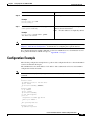
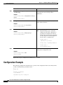
Configuration Example
Configuration Example
The following configuration example shows a portion of the configuration file for the PPPoE scenario
described in this chapter.
The VLAN interface has an IP address of 192.168.1.1 with a subnet mask of 255.255.255.0. NAT is
configured for inside and outside.
Note
Since the VLAN interface is on LAN, we have used a private IP address.
Note
Commands marked by “(default)” are generated automatically when you run the show running-config
command.
!
vpdn enable
vpdn-group 1
request-dialin
protocol pppoe
!
interface vlan 1
ip address 192.168.1.1 255.255.255.0
no ip directed-broadcast (default)
ip nat inside
!
interface FastEthernet 4
ip address 192.1.12.2 255.255.255.0
no ip directed-broadcast (default)
ip nat outside
!
interface dialer 1
ip address negotiated
ppp authentication chap
dialer pool 1
dialer-group 1
!
dialer-list 1 protocol ip permit
ip nat inside source list 1 interface dialer 0 overload
ip classless (default)
ip route 10.10.25.2 0.255.255.255 dialer 0
!
Verifying Your Configuration
Use the show ip nat statistics command in privileged EXEC mode to verify the PPPoE with NAT
configuration. You should see verification output similar to the following example:
Router# show ip nat statistics
Total active translations: 0 (0 static, 0 dynamic; 0 extended)
Outside interfaces:
FastEthernet4
Inside interfaces:
Vlan1
Hits: 0 Misses: 0
CEF Translated packets: 0, CEF Punted packets: 0
Expired translations: 0
Cisco Secure Router 520 Series Software Configuration Guide
3-8
OL-14210-01
Chapter 3
Configuring PPP over Ethernet with NAT
Configuration Example
Dynamic mappings:
-- Inside Source
[Id: 1] access-list 1 interface Dialer0 refcount 0
Queued Packets: 0
Cisco Secure Router 520 Series Software Configuration Guide
OL-14210-01
3-9
Chapter 3
Configuring PPP over Ethernet with NAT
Configuration Example
Cisco Secure Router 520 Series Software Configuration Guide
3-10
OL-14210-01
CH A P T E R
4
Configuring PPP over ATM with NAT
The Cisco Secure Router 520 ADSL-over-POTS and Cisco Secure Router 520 ADSL-over-ISDN routers
support Point-to-Point Protocol over Asynchronous Transfer Mode (PPPoA) clients and network address
translation (NAT).
Multiple PCs can be connected to the LAN behind the router. Before traffic from the PCs is sent to the
PPPoA session, it can be encrypted, filtered, and so forth. PPP over ATM provides a network solution
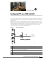
with simplified address handling and straight user verification, as with a dial network. Figure 4-1 shows
a typical deployment scenario with a PPPoA client and NAT configured on the Cisco router. This
scenario uses a single static IP address for the ATM connection.
Figure 4-1
PPP over ATM with NAT
4
5
2
ISP
3
92340
6
1
1
Small business with multiple networked devices—desktops, laptop PCs, switches
2
Fast Ethernet LAN interface (inside interface for NAT, 192.168.1.1/24)
3
PPPoA Client—Cisco Secure Router 520 ADSL-over-POTS or
Cisco Secure Router 520 ADSL-over-ISDN router
4
Point at which NAT occurs
5
ATM WAN interface (outside interface for NAT)
6
PPPoA session between the client and a PPPoA server at the ISP
Cisco Secure Router 520 Series Software Configuration Guide
OL-14210-01
4-1
Chapter 4
Configuring PPP over ATM with NAT
Configure the Dialer Interface
In this scenario, the small business or remote user on the Fast Ethernet LAN can connect to an Internet
service provider (ISP) using the following protocols on the WAN connection:
•
Asymmetric digital subscriber line (ADSL) over plain old telephone service (POTS) using the
Cisco Secure Router 520 ADSL-over-POTS routers
•
ADSL over integrated services digital network (ISDN) using the Cisco Secure
Router 520 ADSL-over-ISDN routers
The Fast Ethernet interface carries the data packet through the LAN and off-loads it to the PPP
connection on the ATM interface. The ATM traffic is encapsulated and sent over the ADSL or ISDN
lines. The dialer interface is used to connect to the ISP.
PPPoA
The PPPoA Client feature on the router provides PPPoA client support on ATM interfaces. A dialer
interface must be used for cloning virtual access. Multiple PPPoA client sessions can be configured on
an ATM interface, but each session must use a separate dialer interface and a separate dialer pool.
A PPPoA session is initiated on the client side by the Cisco Secure Router 520 Series router.
NAT
NAT (represented as the dashed line at the edge of the Cisco router) signifies two addressing domains
and the inside source address. The source list defines how the packet travels through the network.
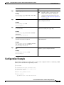
Configuration Tasks
Perform the following tasks to configure this network scenario:
•
Configure the Dialer Interface
•
Configure the ATM WAN Interface
•
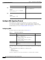
Configure DSL Signaling Protocol
•
Configure Network Address Translation
An example showing the results of these configuration tasks is shown in the “Configuration Example”
section on page 4-9.
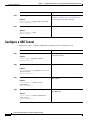
Configure the Dialer Interface
The dialer interface indicates how to handle traffic from the clients, including, for example, default
routing information, the encapsulation protocol, and the dialer pool to use. It is also used for cloning
virtual access. Multiple PPPoA client sessions can be configured on an ATM interface, but each session
must use a separate dialer interface and a separate dialer pool.
Cisco Secure Router 520 Series Software Configuration Guide
4-2
OL-14210-01
Chapter 4
Configuring PPP over ATM with NAT
Configure the Dialer Interface
Perform these steps to configure a dialer interface for the ATM interface on the router, starting in global
configuration mode:
Step 1
Command
Purpose
interface dialer dialer-rotary-group-number
Creates a dialer interface (numbered 0–255), and
enters into interface configuration mode.
Example:
Router(config)# interface dialer 0
Router(config-if)#
Step 2
ip address negotiated
Specifies that the IP address for the dialer
interface is obtained through PPP/IPCP (IP
Control Protocol) address negotiation.
Example:
Router(config-if)# ip address negotiated
Router(config-if)#
Step 3
ip mtu bytes
Sets the size of the IP maximum transmission unit
(MTU). The default minimum is 128 bytes. The
maximum for ATM is 1492 bytes.
Example:
Router(config-if)# ip mtu 1492
Router(config-if)#
Step 4
encapsulation encapsulation-type
Sets the encapsulation type to PPP for the data
packets being transmitted and received.
Example:
Router(config-if)# encapsulation ppp
Router(config-if)#
Step 5
ppp authentication {protocol1 [protocol2...]}
Sets the PPP authentication method.
Example:
The example applies the Challenge Handshake
Authentication Protocol (CHAP).
Router(config-if)# ppp authentication chap
Router(config-if)#
Step 6
dialer pool number
For details about this command and additional
parameters that can be set, see the Cisco IOS
Security Command Reference.
Specifies the dialer pool to use to connect to a
specific destination subnetwork.
Example:
Router(config-if)# dialer pool 1
Router(config-if)#
Step 7
dialer-group group-number
Example:
Router(config-if)# dialer-group 1
Router(config-if)#
Assigns the dialer interface to a dialer group
(1–10).
Tip
Using a dialer group controls access to
your router.
Cisco Secure Router 520 Series Software Configuration Guide
OL-14210-01
4-3
Chapter 4
Configuring PPP over ATM with NAT
Configure the Dialer Interface
Step 8
Command
Purpose
exit
Exits the dialer 0 interface configuration.
Example:
Router(config-if)# exit
Router(config)#
Step 9
dialer-list dialer-group protocol protocol-name
{permit | deny | list access-list-number |
access-group}
Creates a dialer list and associates a dial group
with it. Packets are then forwarded through the
specified interface dialer group.
Example:
For details about this command and additional
parameters that can be set, see the Cisco IOS Dial
Technologies Command Reference.
Router(config)# dialer-list 1 protocol ip
permit
Router(config)#
Step 10
ip route prefix mask {interface-type
interface-number}
Example:
Router(config)# ip route 10.10.25.0
255.255.255.0 dialer 0
Router(config)#
Sets the IP route for the default gateway for the
dialer 0 interface.
For details about this command and additional
parameters that can be set, see the Cisco IOS IP
Command Reference, Volume 1 of 4: Routing
Protocols.
Repeat these steps for any additional dialer interfaces or dialer pools needed.
Cisco Secure Router 520 Series Software Configuration Guide
4-4
OL-14210-01
Chapter 4
Configuring PPP over ATM with NAT
Configure the ATM WAN Interface
Configure the ATM WAN Interface
Perform these steps to configure the ATM interface, beginning in global configuration mode:
Step 1
Command
Purpose
interface type number
Enters interface configuration mode for the ATM
interface (labeled ADSLoPOTS).
Example:
Note
Router(config)# interface atm 0
Router(config-if)#
Step 2
pvc vpi/vci
This interface was initially configured
during basic router configuration. See the
“Configure WAN Interfaces” section on
page 1-4.
Creates an ATM PVC for each end node (up to ten)
with which the router communicates. Enters ATM
virtual circuit configuration mode.
Example:
Router(config-if)# pvc 8/35
Router(config-if-atm-vc)#
When a PVC is defined, AAL5SNAP
encapsulation is defined by default. Use the
encapsulation command to change this, as shown
in Step 3. The VPI and VCI arguments cannot be
simultaneously specified as zero; if one is 0, the
other cannot be 0.
For details about this command and additional
parameters that can be set, see the Cisco IOS
Wide-Area Networking Command Reference.
Step 3
encapsulation {aal5auto | aal5autoppp
virtual-template number [group group-name] |
aal5ciscoppp virtual-template number |
aal5mux protocol | aal5nlpid | aal5snap}
Example:
Specifies the encapsulation type for the PVC and
points back to the dialer interface.
For details about this command and additional
parameters that can be set, see the Cisco IOS
Wide-Area Networking Command Reference.
Router(config-if-atm-vc)# encapsulation
aal5mux ppp dialer
Router(config-if-atm-vc)#
Step 4
dialer pool-member number
Example:
Specifies the ATM interface as a member of a
dialer profile dialing pool. The pool number must
be in the range of 1–255.
Router(config-if-atm-vc)# dialer
pool-member 1
Router(config-if-atm-vc)#
Cisco Secure Router 520 Series Software Configuration Guide
OL-14210-01
4-5
Chapter 4
Configuring PPP over ATM with NAT
Configure DSL Signaling Protocol
Step 5
Command
Purpose
no shutdown
Enables interface and configuration changes just
made to the ATM interface.
Example:
Router(config-if-atm-vc)# no shutdown
Router(config-if)#
Step 6
exit
Exits configuration mode for the ATM interface.
Example:
Router(config-if)# exit
Router(config)#
Configure DSL Signaling Protocol
DSL signaling must be configured on the ATM interface for connection to your ISP. The
Cisco Secure Router 520 ADSL-over-POTS routers support ADSL signaling over POTS and the
Cisco Secure Router 520 ADSL-over-ISDN routers support ADSL signaling over ISDN. To configure
the DSL signaling protocol, see the “Configuring ADSL” section on page 4-6.
Configuring ADSL
The default configuration for ADSL signaling is shown in Table 4-1.
Table 4-1
Default ADSL Configuration
Attribute
Description
Operating mode
Specifies the operating mode of the digital subscriber line Auto
(DSL) for an ATM interface.
•
ADSL over POTS—ANSI or ITU full rate, or
automatic selection.
•
ADSL over ISDN—ITU full rate, ETSI, or
automatic selection.
Default Value
Loss of margin
Specifies the number of times a loss of margin may occur. —
Training log
Toggles between enabling the training log and disabling the Disabled
training log.
If you wish to change any of these settings, use one of the following commands in global configuration
mode:
•
dsl operating-mode (from the ATM interface configuration mode)
•
dsl lom integer
•
dsl enable-training-log
See the Cisco IOS Wide-Area Networking Command Reference for details of these commands.
Cisco Secure Router 520 Series Software Configuration Guide
4-6
OL-14210-01
Chapter 4
Configuring PPP over ATM with NAT
Configure Network Address Translation
Verify the Configuration
You can verify that the configuration is set the way you want by using the show dsl interface atm
command from privileged EXEC mode.
Configure Network Address Translation
Network Address Translation (NAT) translates packets from addresses that match a standard access list,
using global addresses allocated by the dialer interface. Packets that enter the router through the inside
interface, packets sourced from the router, or both are checked against the access list for possible address
translation. You can configure NAT for either static or dynamic address translations.
Perform these steps to configure the outside ATM WAN interface with dynamic NAT, beginning in global
configuration mode:
Step 1
Command
Purpose
ip nat pool name start-ip end-ip {netmask
netmask | prefix-length prefix-length}
Creates pool of global IP addresses for NAT.
Example:
Router(config)# ip nat pool pool1
192.168.1.0 192.168.2.0 netmask
255.255.255.0
Router(config)#
Step 2
ip nat inside source {list access-list-number}
{interface type number | pool name} [overload]
Enables dynamic translation of addresses on the
inside interface.
Example 1:
The first example shows the addresses permitted
by the access list 1 to be translated to one of the
addresses specified in the dialer interface 0.
Router(config)# ip nat inside source list 1
interface dialer 0 overload
The second example shows the addresses
permitted by access list acl1 to be translated to
one of the addresses specified in the NAT pool
pool1.
or
Example 2:
Step 3
Router(config)# ip nat inside source list
acl1 pool pool1
For details about this command and additional
parameters that can be set, as well as information
about enabling static translation, see the
Cisco IOS IP Command Reference, Volume 1 of 4:
Addressing and Services.
interface type number
Enters configuration mode for the VLAN (on
which the Fast Ethernet LAN interfaces
[FE0–FE3] reside) to be the inside interface for
NAT.
Example:
Router(config)# interface vlan 1
Router(config-if)#
Cisco Secure Router 520 Series Software Configuration Guide
OL-14210-01
4-7
Chapter 4
Configuring PPP over ATM with NAT
Configure Network Address Translation
Step 4
Command
Purpose
ip nat {inside | outside}
Applies NAT to the Fast Ethernet LAN interface
as the inside interface.
Example:
For details about this command and additional
parameters that can be set, as well as information
about enabling static translation, see the
Cisco IOS IP Command Reference, Volume 1 of 4:
Addressing and Services.
Router(config-if)# ip nat inside
Router(config-if)#
Step 5
no shutdown
Enables the configuration changes just made to
the Ethernet interface.
Example:
Router(config-if)# no shutdown
Router(config-if)#
Step 6
exit
Exits configuration mode for the Fast Ethernet
interface.
Example:
Router(config-if)# exit
Router(config)#
Step 7
interface type number
Example:
Enters configuration mode for the ATM WAN
interface (ATM0) to be the outside interface for
NAT.
Router(config)# interface atm 0
Router(config-if)#
Step 8
ip nat {inside | outside}
Identifies the specified WAN interface as the NAT
outside interface.
Example:
For details about this command and additional
parameters that can be set, as well as enabling
static translation, see the Cisco IOS IP Command
Reference, Volume 1 of 4: Addressing and
Services.
Router(config-if)# ip nat outside
Router(config-if)#
Step 9
no shutdown
Enables the configuration changes just made to
the Ethernet interface.
Example:
Router(config-if)# no shutdown
Router(config-if)#
Cisco Secure Router 520 Series Software Configuration Guide
4-8
OL-14210-01
Chapter 4
Configuring PPP over ATM with NAT
Configuration Example
Step 10
Command
Purpose
exit
Exits configuration mode for the ATM interface.
Example:
Router(config-if)# exit
Router(config)#
Step 11
access-list access-list-number {deny | permit}
source [source-wildcard]
Defines a standard access list permitting
addresses that need translation.
Note
Example:
All other addresses are implicitly denied.
Router(config)# access-list 1 permit
192.168.1.0 0.0.0.255
Note
If you want to use NAT with a virtual-template interface, you must configure a loopback interface. See
Chapter 1, “Basic Router Configuration,” for information on configuring the loopback interface.
For complete information on NAT commands, see the Cisco IOS Release 12.3 documentation set. For
more general information on NAT concepts, see Appendix B, “Concepts.”
Configuration Example
The following configuration example shows a portion of the configuration file for a client in the PPPoA
scenario described in this chapter.
The VLAN interface has an IP address of 192.168.1.1 with a subnet mask of 255.255.255.0. NAT is
configured for inside and outside.
Note
Commands marked by “(default)” are generated automatically when you run the show running-config
command.
!
interface Vlan1
ip address 192.168.1.1 255.255.255.0
ip nat inside
ip virtual-reassembly (default)
!
interface ATM0
no ip address
ip nat outside
ip virtual-reassembly
no atm ilmi-keepalive
pvc 8/35
encapsulation aal5mux ppp dialer
dialer pool-member 1
!
dsl operating-mode auto
!
interface Dialer0
ip address negotiated
Cisco Secure Router 520 Series Software Configuration Guide
OL-14210-01
4-9
Chapter 4
Configuring PPP over ATM with NAT
Configuration Example
ip mtu 1492
encapsulation ppp
dialer pool 1
dialer-group 1
ppp authentication chap
!
ip classless (default)
!
ip nat pool pool1 192.168.1.0 192.168.2.0 netmask 0.0.0.255
ip nat inside source list 1 interface Dialer0 overload
!
access-list 1 permit 192.168.1.0 0.0.0.255
dialer-list 1 protocol ip permit
ip route 10.10.25.2 0.255.255.255 dialer 0
!
Verifying Your Configuration
Use the show ip nat statistics command in privileged EXEC mode to verify the PPPoA client with NAT
configuration. You should see verification output similar to the following example:
Router# show ip nat statistics
Total active translations: 0 (0 static, 0 dynamic; 0 extended)
Outside interfaces:
ATM0
Inside interfaces:
Vlan1
Hits: 0 Misses: 0
CEF Translated packets: 0, CEF Punted packets: 0
Expired translations: 0
Dynamic mappings:
-- Inside Source
[Id: 1] access-list 1 interface Dialer0 refcount 0
Queued Packets: 0
Cisco Secure Router 520 Series Software Configuration Guide
4-10
OL-14210-01
CH A P T E R
5
Configuring a LAN with DHCP and VLANs
The Cisco Secure Router 520 Series routers support clients on both physical LANs and virtual LANs
(VLANs). The routers can use the Dynamic Host Configuration Protocol (DHCP) to enable automatic
assignment of IP configurations for nodes on these networks.
Figure 5-1 shows a typical deployment scenario with two physical LANs connected by the router and
two VLANs.
Figure 5-1
Physical and Virtual LANs with DHCP Configured on the Cisco Router
3
1
2
92339
4
1
Fast Ethernet LAN (with multiple networked devices)
2
Router and DHCP server—Cisco Secure Router 520 Series router—connected to the Internet
3
VLAN 1
4
VLAN 2
DHCP
DHCP, which is described in RFC 2131, uses a client/server router for address allocation. As an
administrator, you can configure your Cisco Secure Router 520 Series router to act as a DHCP server,
providing IP address assignment and other TCP/IP-oriented configuration information to your
workstations. DHCP frees you from having to manually assign an IP address to each client.
When you configure a DHCP server, you must configure the server properties, policies, and DHCP
options.
Cisco Secure Router 520 Series Software Configuration Guide
OL-14210-01
5-1
Chapter 5
Configuring a LAN with DHCP and VLANs
Configure DHCP
Note
Whenever you change server properties, you must reload the server with the configuration data from the
Network Registrar database.
VLANs
The Cisco Secure Router 520 Series routers support four Fast Ethernet ports on which you can configure
VLANs.
VLANs enable networks to be segmented and formed into logical groups of users, regardless of the
user’s physical location or LAN connection.
Configuration Tasks
Perform the following tasks to configure this network scenario:
Note
•
Configure DHCP
•
Configure VLANs
The procedures in this chapter assume you have already configured basic router features as well as
PPPoE or PPPoA with NAT. If you have not performed these configurations tasks, see Chapter 1, “Basic
Router Configuration,” Chapter 3, “Configuring PPP over Ethernet with NAT,” and Chapter 4,
“Configuring PPP over ATM with NAT” as appropriate for your router.
Configure DHCP
Perform these steps to configure your router for DHCP operation, beginning in global configuration
mode:
Step 1
Command
Purpose
ip domain name name
Identifies the default domain that the router uses to
complete unqualified hostnames (names without a
dotted-decimal domain name).
Example:
Router(config)# ip domain name smallbiz.com
Router(config)#
Step 2
ip name-server server-address1
[server-address2...server-address6]
Specifies the address of one or more Domain
Name System (DNS) servers to use for name and
address resolution.
Example:
Router(config)# ip name-server 192.168.11.12
Router(config)#
Step 3
ip dhcp excluded-address low-address
[high-address]
Specifies IP addresses that the DHCP server
should not assign to DHCP clients. In this
example, we are excluding the router address.
Example:
Router(config)# ip dhcp excluded-address
192.168.9.0
Cisco Secure Router 520 Series Software Configuration Guide
5-2
OL-14210-01
Chapter 5
Configuring a LAN with DHCP and VLANs
Configure DHCP
Step 4
Command
Purpose
ip dhcp pool name
Creates a DHCP address pool on the router and
enters DHCP pool configuration mode. The name
argument can be a string or an integer.
Example:
Router(config)# ip dhcp pool dpool1
Router(dhcp-config)#
Step 5
network network-number [mask | prefix-length]
Defines subnet number (IP) address for the DHCP
address pool, optionally including the mask.
Example:
Router(dhcp-config)# network 10.10.0.0
255.255.255.0
Router(dhcp-config)#
Step 6
import all
Imports DHCP option parameters into the DHCP
portion of the router database.
Example:
Router(dhcp-config)# import all
Router(dhcp-config)#
Step 7
default-router address [address2...address8]
Specifies up to 8 default routers for a DHCP client.
Example:
Router(dhcp-config)# default-router
10.10.10.10
Router(dhcp-config)#
Step 8
dns-server address [address2...address8]
Specifies up to 8 DNS servers available to a DHCP
client.
Example:
Router(dhcp-config)# dns-server 192.168.35.2
Router(dhcp-config)#
Step 9
domain-name domain
Specifies the domain name for a DHCP client.
Example:
Router(dhcp-config)# domain-name cisco.com
Router(dhcp-config)#
Step 10
exit
Exits DHCP configuration mode, and enters
global configuration mode.
Example:
Router(dhcp-config)# exit
Router(config)#
Cisco Secure Router 520 Series Software Configuration Guide
OL-14210-01
5-3
Chapter 5
Configuring a LAN with DHCP and VLANs
Configure DHCP
Configuration Example
The following configuration example shows a portion of the configuration file for the DCHP
configuration described in this chapter.
ip dhcp excluded-address 192.168.9.0
!
ip dhcp pool dpool1
import all
network 10.10.0.0 255.255.255.0
default-router 10.10.10.10
dns-server 192.168.35.2
domain-name cisco.com
!
ip domain name smallbiz.com
ip name-server 192.168.11.12
Verify Your DHCP Configuration
Use the following commands to view your DHCP configuration.
•
show ip dhcp import—Displays the optional parameters imported into the DHCP server database.
•
show ip dhcp pool—Displays information about the DHCP address pools.
•
show ip dhcp server statistics—Displays the DHCP server statistics, such as the number of address
pools, bindings, and so forth.
Router# show ip dhcp import
Address Pool Name: dpool1
Router# show ip dhcp pool
Pool dpool1 :
Utilization mark (high/low)
: 100 / 0
Subnet size (first/next)
: 0 / 0
Total addresses
: 254
Leased addresses
: 0
Pending event
: none
1 subnet is currently in the pool :
Current index
IP address range
10.10.0.1
10.10.0.1
- 10.10.0.254
Router# show ip dhcp
Memory usage
Address pools
Database agents
Automatic bindings
Manual bindings
Expired bindings
Malformed messages
Secure arp entries
server statistics
15419
1
0
0
0
0
0
0
Message
BOOTREQUEST
DHCPDISCOVER
DHCPREQUEST
DHCPDECLINE
DHCPRELEASE
DHCPINFORM
Received
0
0
0
0
0
0
Leased addresses
0
Cisco Secure Router 520 Series Software Configuration Guide
5-4
OL-14210-01
Chapter 5
Configuring a LAN with DHCP and VLANs
Configure VLANs
Message
BOOTREPLY
DHCPOFFER
DHCPACK
DHCPNAK
Router#
Sent
0
0
0
0
Configure VLANs
Perform these steps to configure VLANs on your router, beginning in privileged EXEC mode:
Step 1
Command
Purpose
vlan database
Enters VLAN configuration mode.
Example:
Router# vlan database
Router(vlan)#
Step 2
vlan vlan-id [media type] [name vlan-name]
Adds VLANs, with identifiers ranging from 2 to
1001.
Example:
For details about this command and additional
parameters that can be set, see the Cisco IOS
Switching Services Command Reference.
Router(vlan)# vlan 2 media ethernet name
VLAN0002
VLAN 2 added:
Name: VLAN0002
Media type: ETHERNET
Router(vlan)# vlan 3 media ethernet name
red-vlan
VLAN 3 added:
Name: red-vlan
Media type: ETHERNET
Router(vlan)#
Step 3
exit
Example:
Updates the VLAN database, propagates it
throughout the administrative domain, and returns
to privileged EXEC mode.
Router(vlan)# exit
Router#
Cisco Secure Router 520 Series Software Configuration Guide
OL-14210-01
5-5
Chapter 5
Configuring a LAN with DHCP and VLANs
Configure VLANs
Assign a Switch Port to a VLAN
Perform these steps to assign a switch port to a VLAN, beginning in global configuration mode:
Step 1
Command
Purpose
interface switch port id
Specifies the switch port that you want to assign
to the VLAN.
Example:
Router(config)# interface FastEthernet 2
Router(config-if)#
Step 2
switchport access vlan vlan-id
Assigns a port to the VLAN.
Example:
Router(config-if)# switchport access vlan 2
Router(config-if)#
Step 3
end
Exits interface mode and returns to privileged
EXEC mode.
Example:
Router(config-if)# end
Router#
Verify Your VLAN Configuration
Use the following commands to view your VLAN configuration.
•
show—Entered from VLAN database mode. Displays summary configuration information for all
configured VLANs.
•
show vlan-switch—Entered from privileged EXEC mode. Displays detailed configuration
information for all configured VLANs.
Router# vlan database
Router(vlan)# show
VLAN ISL Id: 1
Name: default
Media Type: Ethernet
VLAN 802.10 Id: 100001
State: Operational
MTU: 1500
Translational Bridged VLAN: 1002
Translational Bridged VLAN: 1003
VLAN ISL Id: 2
Name: VLAN0002
Media Type: Ethernet
VLAN 802.10 Id: 100002
State: Operational
MTU: 1500
Cisco Secure Router 520 Series Software Configuration Guide
5-6
OL-14210-01
Chapter 5
Configuring a LAN with DHCP and VLANs
Configure VLANs
VLAN ISL Id: 3
Name: red-vlan
Media Type: Ethernet
VLAN 802.10 Id: 100003
State: Operational
MTU: 1500
VLAN ISL Id: 1002
Name: fddi-default
Media Type: FDDI
VLAN 802.10 Id: 101002
State: Operational
MTU: 1500
Bridge Type: SRB
Translational Bridged VLAN: 1
Translational Bridged VLAN: 1003
VLAN ISL Id: 1003
Name: token-ring-default
Media Type: Token Ring
VLAN 802.10 Id: 101003
State: Operational
MTU: 1500
Bridge Type: SRB
Ring Number: 0
Bridge Number: 1
Parent VLAN: 1005
Maximum ARE Hop Count: 7
Maximum STE Hop Count: 7
Backup CRF Mode: Disabled
Translational Bridged VLAN: 1
Translational Bridged VLAN: 1002
VLAN ISL Id: 1004
Name: fddinet-default
Media Type: FDDI Net
VLAN 802.10 Id: 101004
State: Operational
MTU: 1500
Bridge Type: SRB
Bridge Number: 1
STP Type: IBM
VLAN ISL Id: 1005
Name: trnet-default
Media Type: Token Ring Net
VLAN 802.10 Id: 101005
State: Operational
MTU: 1500
Bridge Type: SRB
Bridge Number: 1
STP Type: IBM
Router# show vlan-switch
VLAN
---1
2
1002
1003
1004
1005
Name
-------------------------------default
VLAN0002
fddi-default
token-ring-default
fddinet-default
trnet-default
Status
--------active
active
active
active
active
active
Ports
------------------------------Fa0, Fa1, Fa3
Fa2
Cisco Secure Router 520 Series Software Configuration Guide
OL-14210-01
5-7
Chapter 5
Configuring a LAN with DHCP and VLANs
Configure VLANs
VLAN
---1
2
1002
1003
1004
1005
Type
----enet
enet
fddi
tr
fdnet
trnet
SAID
---------100001
100002
101002
101003
101004
101005
MTU
----1500
1500
1500
1500
1500
1500
Parent
-----1005
-
RingNo
-----0
-
BridgeNo
-------1
1
Stp
---ibm
ibm
BrdgMode
-------srb
-
Trans1
-----1002
0
1
1
0
0
Trans2
-----1003
0
1003
1002
0
0
Cisco Secure Router 520 Series Software Configuration Guide
5-8
OL-14210-01
CH A P T E R
6
Configuring a VPN Using Easy VPN and an IPsec
Tunnel
The Cisco Secure Router 520 Series routers support the creation of Virtual Private Networks (VPNs).
Cisco routers and other broadband devices provide high-performance connections to the Internet, but
many applications also require the security of VPN connections which perform a high level of
authentication and which encrypt the data between two particular endpoints.
Two types of VPNs are supported—site-to-site and remote access. Site-to-site VPNs are used to connect
branch offices to corporate offices, for example. Remote access VPNs are used by remote clients to log
in to a corporate network.
The example in this chapter illustrates the configuration of a remote access VPN that uses the Cisco Easy
VPN and an IPsec tunnel to configure and secure the connection between the remote client and the
corporate network. Figure 6-1 shows a typical deployment scenario.
Figure 6-1
Remote Access VPN Using IPsec Tunnel
5
3
2
4
6
121782
Internet
1
1
Remote, networked users
2
VPN client—Cisco Secure Router 520 Series router
3
Router—Providing the corporate office network access
Cisco Secure Router 520 Series Software Configuration Guide
OL-14210-01
6-1
Chapter 6
Configuring a VPN Using Easy VPN and an IPsec Tunnel
4
VPN server—Easy VPN server; for example, a Cisco Adaptive Security Appliance (ASA) Series
concentrator with outside interface address 210.110.101.1
5
Corporate office with a network address of 10.1.1.1
6
IPsec tunnel
Cisco Easy VPN
The Cisco Easy VPN client feature eliminates much of the tedious configuration work by implementing
the Cisco Unity Client protocol. This protocol allows most VPN parameters, such as internal IP
addresses, internal subnet masks, DHCP server addresses, WINS server addresses, and split-tunneling
flags, to be defined at a VPN server, such as a Cisco Adaptive Security Appliance (ASA) Series
concentrator that is acting as an IPsec server.
An Easy VPN server–enabled device can terminate VPN tunnels initiated by mobile and remote workers
who are running Cisco Easy VPN Remote software on PCs. Easy VPN server–enabled devices allow
remote routers to act as Easy VPN Remote nodes.
The Cisco Easy VPN client feature can be configured in one of two modes—client mode or network
extension mode. Client mode is the default configuration and allows only devices at the client site to
access resources at the central site. Resources at the client site are unavailable to the central site.
Network extension mode allows users at the central site (where the Cisco ASA Series concentrator is
located) to access network resources on the client site.
After the IPsec server has been configured, a VPN connection can be created with minimal configuration
on an IPsec client, such as a supported Cisco Secure Router 520 Series router. When the IPsec client
initiates the VPN tunnel connection, the IPsec server pushes the IPsec policies to the IPsec client and
creates the corresponding VPN tunnel connection.
Note
The Cisco Easy VPN client feature supports configuration of only one destination peer. If your
application requires creation of multiple VPN tunnels, you must manually configure the IPsec VPN and
Network Address Translation/Peer Address Translation (NAT/PAT) parameters on both the client and the
server.
Configuration Tasks
Perform the following tasks to configure your router for this network scenario:
•
Configure the IKE Policy
•
Configure Group Policy Information
•
Apply Mode Configuration to the Crypto Map
•
Enable Policy Lookup
•
Configure IPsec Transforms and Protocols
•
Configure the IPsec Crypto Method and Parameters
•
Apply the Crypto Map to the Physical Interface
•
Create an Easy VPN Remote Configuration
An example showing the results of these configuration tasks is provided in the “Configuration Example”
section on page 6-10.
Cisco Secure Router 520 Series Software Configuration Guide
6-2
OL-14210-01
Chapter 6
Configuring a VPN Using Easy VPN and an IPsec Tunnel
Configure the IKE Policy
Note
The procedures in this chapter assume that you have already configured basic router features as well as
PPPoE or PPPoA with NAT, DCHP and VLANs. If you have not performed these configurations tasks,
see Chapter 1, “Basic Router Configuration,” Chapter 3, “Configuring PPP over Ethernet with NAT,”
Chapter 4, “Configuring PPP over ATM with NAT,” and Chapter 5, “Configuring a LAN with DHCP and
VLANs” as appropriate for your router.
Note
The examples shown in this chapter refer only to the endpoint configuration on the
Cisco Secure Router 520 Series router. Any VPN connection requires both endpoints be configured
properly to function. See the software configuration documentation as needed to configure VPN for
other router models.
Configure the IKE Policy
Perform these steps to configure the Internet Key Exchange (IKE) policy, beginning in global
configuration mode:
Step 1
Command or Action
Purpose
crypto isakmp policy priority
Creates an IKE policy that is used during IKE
negotiation. The priority is a number from 1 to
10000, with 1 being the highest.
Example:
Step 2
Router(config)# crypto isakmp policy 1
Router(config-isakmp)#
Also enters the Internet Security Association Key
and Management Protocol (ISAKMP) policy
configuration mode.
encryption {des | 3des | aes | aes 192 | aes 256}
Specifies the encryption algorithm used in the IKE
policy.
Example:
The example specifies 168-bit data encryption
standard (DES).
Router(config-isakmp)# encryption 3des
Router(config-isakmp)#
Step 3
hash {md5 | sha}
Specifies the hash algorithm used in the IKE
policy.
Example:
The example specifies the Message Digest 5
(MD5) algorithm. The default is Secure Hash
standard (SHA-1).
Router(config-isakmp)# hash md5
Router(config-isakmp)#
Step 4
authentication {rsa-sig | rsa-encr | pre-share}
Specifies the authentication method used in the
IKE policy.
Example:
The example specifies a pre-shared key.
Router(config-isakmp)# authentication
pre-share
Router(config-isakmp)#
Cisco Secure Router 520 Series Software Configuration Guide
OL-14210-01
6-3
Chapter 6
Configuring a VPN Using Easy VPN and an IPsec Tunnel
Configure Group Policy Information
Step 5
Command or Action
Purpose
group {1 | 2 | 5}
Specifies the Diffie-Hellman group to be used in
an IKE policy.
Example:
Router(config-isakmp)# group 2
Router(config-isakmp)#
Step 6
lifetime seconds
Specifies the lifetime, 60–86400 seconds, for an
IKE security association (SA).
Example:
Router(config-isakmp)# lifetime 480
Router(config-isakmp)#
Step 7
exit
Exits IKE policy configuration mode, and enters
global configuration mode.
Example:
Router(config-isakmp)# exit
Router(config)#
Configure Group Policy Information
Perform these steps to configure the group policy, beginning in global configuration mode:
Step 1
Command or Action
Purpose
crypto isakmp client configuration group
{group-name | default}
Creates an IKE policy group containing attributes
to be downloaded to the remote client.
Example:
Also enters the Internet Security Association Key
and Management Protocol (ISAKMP) group
policy configuration mode.
Router(config)# crypto isakmp client
configuration group rtr-remote
Router(config-isakmp-group)#
Step 2
key name
Specifies the IKE pre-shared key for the group
policy.
Example:
Router(config-isakmp-group)# key
secret-password
Router(config-isakmp-group)#
Step 3
dns primary-server
Example:
Router(config-isakmp-group)# dns 10.50.10.1
Router(config-isakmp-group)#
Specifies the primary Domain Name System
(DNS) server for the group.
Note
You may also want to specify Windows
Internet Naming Service (WINS) servers
for the group by using the wins command.
Cisco Secure Router 520 Series Software Configuration Guide
6-4
OL-14210-01
Chapter 6
Configuring a VPN Using Easy VPN and an IPsec Tunnel
Apply Mode Configuration to the Crypto Map
Step 4
Command or Action
Purpose
domain name
Specifies group domain membership.
Example:
Router(config-isakmp-group)# domain
company.com
Router(config-isakmp-group)#
Step 5
exit
Exits IKE group policy configuration mode, and
enters global configuration mode.
Example:
Router(config-isakmp-group)# exit
Router(config)#
Step 6
ip local pool {default | poolname}
[low-ip-address [high-ip-address]]
Specifies a local address pool for the group.
For details about this command and additional
parameters that can be set, see the Cisco IOS Dial
Technologies Command Reference.
Example:
Router(config)# ip local pool dynpool
30.30.30.20 30.30.30.30
Router(config)#
Apply Mode Configuration to the Crypto Map
Perform these steps to apply mode configuration to the crypto map, beginning in global configuration
mode:
Command or Action
Step 1
Purpose
crypto map map-name isakmp authorization list Applies mode configuration to the crypto map and
list-name
enables key lookup (IKE queries) for the group
policy from an authentication, authorization, and
accounting (AAA) server.
Example:
Router(config)# crypto map dynmap isakmp
authorization list rtr-remote
Router(config)#
Step 2
crypto map tag client configuration address
[initiate | respond]
Configures the router to reply to mode
configuration requests from remote clients.
Example:
Router(config)# crypto map dynmap client
configuration address respond
Router(config)#
Cisco Secure Router 520 Series Software Configuration Guide
OL-14210-01
6-5
Chapter 6
Configuring a VPN Using Easy VPN and an IPsec Tunnel
Enable Policy Lookup
Enable Policy Lookup
Perform these steps to enable policy lookup through AAA, beginning in global configuration mode:
Step 1
Command or Action
Purpose
aaa new-model
Enables the AAA access control model.
Example:
Router(config)# aaa new-model
Router(config)#
Step 2
aaa authentication login {default | list-name}
method1 [method2...]
Example:
Router(config)# aaa authentication login
rtr-remote local
Router(config)#
Step 3
This example uses a local authentication database.
You could also use a RADIUS server for this. For
details, see the Cisco IOS Security Configuration
Guide and Cisco IOS Security Command
Reference.
aaa authorization {network | exec | commands Specifies AAA authorization of all
level | reverse-access | configuration} {default | network-related service requests, including PPP,
list-name} [method1 [method2...]]
and specifies the method of authorization.
Example:
Router(config)# aaa authorization network
rtr-remote local
Router(config)#
Step 4
Specifies AAA authentication of selected users at
login, and specifies the method used.
username name {nopassword | password
password | password encryption-type
encrypted-password}
Example:
This example uses a local authorization database.
You could also use a RADIUS server for this. For
details, see the Cisco IOS Security Configuration
Guide and Cisco IOS Security Command
Reference.
Establishes a username-based authentication
system.
This example implements a username of Cisco
with an encrypted password of Cisco.
Router(config)# username Cisco password 0
Cisco
Router(config)#
Configure IPsec Transforms and Protocols
A transform set represents a certain combination of security protocols and algorithms. During IKE
negotiation, the peers agree to use a particular transform set for protecting data flow.
During IKE negotiations, the peers search in multiple transform sets for a transform that is the same at
both peers. When such a transform set is found, it is selected and applied to the protected traffic as a part
of both peers’ configurations.
Cisco Secure Router 520 Series Software Configuration Guide
6-6
OL-14210-01
Chapter 6
Configuring a VPN Using Easy VPN and an IPsec Tunnel
Configure the IPsec Crypto Method and Parameters
Perform these steps to specify the IPsec transform set and protocols, beginning in global configuration
mode:
Step 1
Command or Action
Purpose
crypto ipsec transform-set transform-set-name
transform1 [transform2] [transform3]
[transform4]
Defines a transform set—an acceptable
combination of IPsec security protocols and
algorithms.
Example:
See the Cisco IOS Security Command Reference
for detail about the valid transforms and
combinations.
Router(config)# crypto ipsec transform-set
vpn1 esp-3des esp-sha-hmac
Router(cfg-crypto-trans)#
Step 2
crypto ipsec security-association lifetime
{seconds seconds | kilobytes kilobytes}
Specifies global lifetime values used when IPsec
security associations are negotiated.
Example:
See the Cisco IOS Security Command Reference
for details.
Router(cfg-crypto-trans)# crypto ipsec
security-association lifetime seconds 86400
Router(config)#
Note
With manually established security associations, there is no negotiation with the peer, and both sides
must specify the same transform set.
Configure the IPsec Crypto Method and Parameters
A dynamic crypto map policy processes negotiation requests for new security associations from remote
IPsec peers, even if the router does not know all the crypto map parameters (for example, IP address).
Perform these steps to configure the IPsec crypto method, beginning in global configuration mode:
Step 1
Command or Action
Purpose
crypto dynamic-map dynamic-map-name
dynamic-seq-num
Creates a dynamic crypto map entry and enters
crypto map configuration mode.
Example:
See the Cisco IOS Security Command Reference
for more detail about this command.
Router(config)# crypto dynamic-map dynmap 1
Router(config-crypto-map)#
Step 2
set transform-set transform-set-name
[transform-set-name2...transform-set-name6]
Specifies which transform sets can be used with
the crypto map entry.
Example:
Router(config-crypto-map)# set
transform-set vpn1
Router(config-crypto-map)#
Cisco Secure Router 520 Series Software Configuration Guide
OL-14210-01
6-7
Chapter 6
Configuring a VPN Using Easy VPN and an IPsec Tunnel
Apply the Crypto Map to the Physical Interface
Step 3
Command or Action
Purpose
reverse-route
Creates source proxy information for the crypto
map entry.
Example:
See the Cisco IOS Security Command Reference
for details.
Router(config-crypto-map)# reverse-route
Router(config-crypto-map)#
Step 4
exit
Returns to global configuration mode.
Example:
Router(config-crypto-map)# exit
Router(config)#
Step 5
crypto map map-name seq-num [ipsec-isakmp]
[dynamic dynamic-map-name] [discover]
[profile profile-name]
Creates a crypto map profile.
Example:
Router(config)# crypto map static-map 1
ipsec-isakmp dynamic dynmap
Router(config)#
Apply the Crypto Map to the Physical Interface
The crypto maps must be applied to each interface through which IP Security (IPsec) traffic flows.
Applying the crypto map to the physical interface instructs the router to evaluate all the traffic against
the security associations database. With the default configurations, the router provides secure
connectivity by encrypting the traffic sent between remote sites. However, the public interface still
allows the rest of the traffic to pass and provides connectivity to the Internet.
Perform these steps to apply a crypto map to an interface, beginning in global configuration mode:
Step 1
Command or Action
Purpose
interface type number
Enters the interface configuration mode for the
interface to which you want the crypto map
applied.
Example:
Router(config)# interface fastethernet 4
Router(config-if)#
Cisco Secure Router 520 Series Software Configuration Guide
6-8
OL-14210-01
Chapter 6
Configuring a VPN Using Easy VPN and an IPsec Tunnel
Create an Easy VPN Remote Configuration
Step 2
Command or Action
Purpose
crypto map map-name
Applies the crypto map to the interface.
Example:
See the Cisco IOS Security Command Reference
for more detail about this command.
Router(config-if)# crypto map static-map
Router(config-if)#
Step 3
exit
Returns to global configuration mode.
Example:
Router(config-crypto-map)# exit
Router(config)#
Create an Easy VPN Remote Configuration
The router acting as the IPsec remote router must create an Easy VPN remote configuration and assign
it to the outgoing interface.
Perform these steps to create the remote configuration, beginning in global configuration mode:
Step 1
Command or Action
Purpose
crypto ipsec client ezvpn name
Creates a Cisco Easy VPN remote configuration,
and enters Cisco Easy VPN remote configuration
mode.
Example:
Router(config)# crypto ipsec client ezvpn
ezvpnclient
Router(config-crypto-ezvpn)#
Step 2
group group-name key group-key
Specifies the IPsec group and IPsec key value for
the VPN connection.
Example:
Router(config-crypto-ezvpn)# group
ezvpnclient key secret-password
Router(config-crypto-ezvpn)#
Step 3
peer {ipaddress | hostname}
Specifies the peer IP address or hostname for the
VPN connection.
Example:
Note
Router(config-crypto-ezvpn)# peer
192.168.100.1
Router(config-crypto-ezvpn)#
Step 4
mode {client | network-extension | network
extension plus}
A hostname can be specified only when
the router has a DNS server available for
hostname resolution.
Specifies the VPN mode of operation.
Example:
Router(config-crypto-ezvpn)# mode client
Router(config-crypto-ezvpn)#
Cisco Secure Router 520 Series Software Configuration Guide
OL-14210-01
6-9
Chapter 6
Configuring a VPN Using Easy VPN and an IPsec Tunnel
Verifying Your Easy VPN Configuration
Step 5
Command or Action
Purpose
exit
Returns to global configuration mode.
Example:
Router(config-crypto-ezvpn)# exit
Router(config)#
Step 6
interface type number
Example:
Router(config)# interface fastethernet 4
Router(config-if)#
Step 7
Enters the interface configuration mode for the
interface to which you want the Cisco Easy VPN
remote configuration applied.
Note
For routers with an ATM WAN interface,
this command would be interface atm 0.
crypto ipsec client ezvpn name [outside | inside] Assigns the Cisco Easy VPN remote configuration
to the WAN interface, causing the router to
automatically create the NAT or port address
Example:
translation (PAT) and access list configuration
Router(config-if)# crypto ipsec client
needed for the VPN connection.
ezvpn ezvpnclient outside
Router(config-if)#
Step 8
exit
Returns to global configuration mode.
Example:
Router(config-crypto-ezvpn)# exit
Router(config)#
Verifying Your Easy VPN Configuration
router# show crypto ipsec client ezvpn
Tunnel name :ezvpnclient
Inside interface list:vlan 1
Outside interface:fastethernet 4
Current State:IPSEC_ACTIVE
Last Event:SOCKET_UP
Address:8.0.0.5
Mask:255.255.255.255
Default Domain:cisco.com
Configuration Example
The
and
!
aaa
!
aaa
aaa
aaa
!
following configuration example shows a portion of the configuration file for the VPN
IPsec tunnel described in this chapter.
new-model
authentication login rtr-remote local
authorization network rtr-remote local
session-id common
Cisco Secure Router 520 Series Software Configuration Guide
6-10
OL-14210-01
Chapter 6
Configuring a VPN Using Easy VPN and an IPsec Tunnel
Configuration Example
username Cisco password 0 Cisco
!
crypto isakmp policy 1
encryption 3des
authentication pre-share
group 2
lifetime 480
!
crypto isakmp client configuration group rtr-remote
key secret-password
dns 10.50.10.1 10.60.10.1
domain company.com
pool dynpool
!
crypto ipsec transform-set vpn1 esp-3des esp-sha-hmac
!
crypto ipsec security-association lifetime seconds 86400
!
crypto dynamic-map dynmap 1
set transform-set vpn1
reverse-route
!
crypto map static-map 1 ipsec-isakmp dynamic dynmap
crypto map dynmap isakmp authorization list rtr-remote
crypto map dynmap client configuration address respond
crypto ipsec client ezvpn ezvpnclient
connect auto
group 2 key secret-password
mode client
peer 192.168.100.1
!
interface fastethernet 4
crypto ipsec client ezvpn ezvpnclient outside
crypto map static-map
!
interface vlan 1
crypto ipsec client ezvpn ezvpnclient inside
!
Cisco Secure Router 520 Series Software Configuration Guide
OL-14210-01
6-11
Chapter 6
Configuring a VPN Using Easy VPN and an IPsec Tunnel
Configuration Example
Cisco Secure Router 520 Series Software Configuration Guide
6-12
OL-14210-01
CH A P T E R
7
Configuring VPNs Using an IPsec Tunnel and
Generic Routing Encapsulation
The Cisco Secure Router 520 Series routers support the creation of virtual private networks (VPNs).
Cisco routers and other broadband devices provide high-performance connections to the Internet, but
many applications also require the security of VPN connections which perform a high level of
authentication and which encrypt the data between two particular endpoints.
Two types of VPNs are supported—site-to-site and remote access. Site-to-site VPNs are used to connect
branch offices to corporate offices, for example. Remote access VPNs are used by remote clients to log
in to a corporate network.
The example in this chapter illustrates the configuration of a site-to-site VPN that uses IPsec and the
generic routing encapsulation (GRE) protocol to secure the connection between the branch office and
the corporate network. Figure 7-1 shows a typical deployment scenario.
Figure 7-1
Site-to-Site VPN Using an IPsec Tunnel and GRE
8
3
2
6
4
Internet
5
121783
1
7
9
1
Branch office containing multiple LANs and VLANs
2
Fast Ethernet LAN interface—With address 192.168.0.0/16 (also the inside interface for NAT)
3
VPN client—Cisco Secure Router 520 Series routers
4
Fast Ethernet or ATM interface—With address 200.1.1.1 (also the outside interface for NAT)
5
LAN interface—Connects to the Internet; with outside interface address of 210.110.101.1
6
VPN client—Another router, which controls access to the corporate network
7
LAN interface—Connects to the corporate network, with inside interface address of 10.1.1.1
8
Corporate office network
9
IPsec tunnel with GRE
Cisco Secure Router 520 Series Software Configuration Guide
OL-14210-01
7-1
Chapter 7
Configuring VPNs Using an IPsec Tunnel and Generic Routing Encapsulation
Configure a VPN
GRE Tunnels
GRE tunnels are typically used to establish a VPN between the Cisco router and a remote device that
controls access to a private network, such as a corporate network. Traffic forwarded through the GRE
tunnel is encapsulated and routed out onto the physical interface of the router. When a GRE interface is
used, the Cisco router and the router that controls access to the corporate network can support dynamic
IP routing protocols to exchange routing updates over the tunnel, and to enable IP multicast traffic.
Supported IP routing protocols include Routing Information Protocol (RIP) and Intermediate
System-to-Intermediate System (IS-IS).
Note
When IP Security (IPsec) is used with GRE, the access list for encrypting traffic does not list the desired
end network and applications, but instead refers to the permitted source and destination of the GRE
tunnel in the outbound direction. All packets forwarded to the GRE tunnel are encrypted if no further
access control lists (ACLs) are applied to the tunnel interface.
VPNs
VPN configuration information must be configured on both endpoints; for example, on your Cisco router
and at the remote user, or on your Cisco router and on another router. You must specify parameters, such
as internal IP addresses, internal subnet masks, DHCP server addresses, and Network Address
Translation (NAT).
Configuration Tasks
Perform the following tasks to configure this network scenario:
•
Configure a VPN
•
Configure a GRE Tunnel
A configuration example showing the results of these configuration tasks is provided in the
“Configuration Example” section on page 7-9.
Note
The procedures in this chapter assume that you have already configured basic router features as well as
PPPoE or PPPoA with NAT, DCHP, and VLANs. If you have not performed these configurations tasks,
see Chapter 1, “Basic Router Configuration,” Chapter 3, “Configuring PPP over Ethernet with NAT,”
Chapter 4, “Configuring PPP over ATM with NAT,” and Chapter 5, “Configuring a LAN with DHCP and
VLANs,” as appropriate for your router.
Configure a VPN
Perform the following tasks to configure a VPN over an IPsec tunnel:
•
Configure the IKE Policy
•
Configure Group Policy Information
•
Enable Policy Lookup
•
Configure IPsec Transforms and Protocols
•
Configure the IPsec Crypto Method and Parameters
•
Apply the Crypto Map to the Physical Interface
Cisco Secure Router 520 Series Software Configuration Guide
7-2
OL-14210-01
Chapter 7
Configuring VPNs Using an IPsec Tunnel and Generic Routing Encapsulation
Configure a VPN
Configure the IKE Policy
Perform these steps to configure the Internet Key Exchange (IKE) policy, beginning in global
configuration mode:
Step 1
Command or Action
Purpose
crypto isakmp policy priority
Creates an IKE policy that is used during IKE
negotiation. The priority is a number from 1 to
10000, with 1 being the highest.
Example:
Step 2
Router(config)# crypto isakmp policy 1
Router(config-isakmp)#
Also enters Internet Security Association and Key
Management Protocol (ISAKMP) policy
configuration mode.
encryption {des | 3des | aes | aes 192 | aes 256}
Specifies the encryption algorithm used in the
IKE policy.
Example:
The example uses 168-bit Data Encryption
Standard (DES).
Router(config-isakmp)# encryption 3des
Router(config-isakmp)#
Step 3
hash {md5 | sha}
Specifies the hash algorithm used in the IKE
policy.
Example:
The example specifies the Message Digest 5
(MD5) algorithm. The default is Secure Hash
standard (SHA-1).
Router(config-isakmp)# hash md5
Router(config-isakmp)#
Step 4
authentication {rsa-sig | rsa-encr | pre-share}
Specifies the authentication method used in the
IKE policy.
Example:
The example uses a pre-shared key.
Router(config-isakmp)# authentication
pre-share
Router(config-isakmp)#
Step 5
group {1 | 2 | 5}
Specifies the Diffie-Hellman group to be used in
the IKE policy.
Example:
Router(config-isakmp)# group 2
Router(config-isakmp)#
Step 6
lifetime seconds
Specifies the lifetime, 60–86400 seconds, for an
IKE security association (SA).
Example:
Router(config-isakmp)# lifetime 480
Router(config-isakmp)#
Step 7
exit
Exits IKE policy configuration mode, and enters
global configuration mode.
Example:
Router(config-isakmp)# exit
Router(config)#
Cisco Secure Router 520 Series Software Configuration Guide
OL-14210-01
7-3
Chapter 7
Configuring VPNs Using an IPsec Tunnel and Generic Routing Encapsulation
Configure a VPN
Configure Group Policy Information
Perform these steps to configure the group policy, beginning in global configuration mode:
Step 1
Command or Action
Purpose
crypto isakmp client configuration group
{group-name | default}
Creates an IKE policy group that contains
attributes to be downloaded to the remote client.
Example:
Also enters Internet Security Association Key
Management Protocol (ISAKMP) policy
configuration mode.
Router(config)# crypto isakmp client
configuration group rtr-remote
Router(config-isakmp-group)#
Step 2
key name
Specifies the IKE pre-shared key for the group
policy.
Example:
Router(config-isakmp-group)# key
secret-password
Router(config-isakmp-group)#
Step 3
dns primary-server
Example:
Router(config-isakmp-group)# dns 10.50.10.1
Router(config-isakmp-group)#
Step 4
domain name
Specifies the primary Domain Name Service
(DNS) server for the group.
Note
You may also want to specify Windows
Internet Naming Service (WINS) servers
for the group by using the wins command.
Specifies group domain membership.
Example:
Router(config-isakmp-group)# domain
company.com
Router(config-isakmp-group)#
Step 5
exit
Exits IKE group policy configuration mode, and
enters global configuration mode.
Example:
Router(config-isakmp-group)# exit
Router(config)#
Step 6
ip local pool {default | poolname}
[low-ip-address [high-ip-address]]
Example:
Specifies a local address pool for the group.
For details about this command and additional
parameters that can be set, see the Cisco IOS Dial
Technologies Command Reference.
Router(config)# ip local pool dynpool
30.30.30.20 30.30.30.30
Router(config)#
Cisco Secure Router 520 Series Software Configuration Guide
7-4
OL-14210-01
Chapter 7
Configuring VPNs Using an IPsec Tunnel and Generic Routing Encapsulation
Configure a VPN
Enable Policy Lookup
Perform these steps to enable policy lookup through AAA, beginning in global configuration mode:
Step 1
Command or Action
Purpose
aaa new-model
Enables the AAA access control model.
Example:
Router(config)# aaa new-model
Router(config)#
Step 2
aaa authentication login {default | list-name}
method1 [method2...]
Example:
Router(config)# aaa authentication login
rtr-remote local
Router(config)#
Step 3
This example uses a local authentication database.
You could also use a RADIUS server for this. See
the Cisco IOS Security Configuration Guide and
the Cisco IOS Security Command Reference for
details.
aaa authorization {network | exec | commands Specifies AAA authorization of all
level | reverse-access | configuration} {default | network-related service requests, including PPP,
list-name} [method1 [method2...]]
and the method used to do so.
Example:
Router(config)# aaa authorization network
rtr-remote local
Router(config)#
Step 4
Specifies AAA authentication of selected users at
login, and specifies the method used.
username name {nopassword | password
password | password encryption-type
encrypted-password}
Example:
This example uses a local authorization database.
You could also use a RADIUS server for this. See
the Cisco IOS Security Configuration Guide and
the Cisco IOS Security Command Reference for
details.
Establishes a username-based authentication
system.
This example implements a username of cisco
with an encrypted password of cisco.
Router(config)# username cisco password 0
cisco
Router(config)#
Configure IPsec Transforms and Protocols
A transform set represents a certain combination of security protocols and algorithms. During IKE
negotiation, the peers agree to use a particular transform set for protecting data flow.
During IKE negotiations, the peers search in multiple transform sets for a transform that is the same at
both peers. When such a transform set is found, it is selected and applied to the protected traffic as a part
of both peers’ configurations.
Cisco Secure Router 520 Series Software Configuration Guide
OL-14210-01
7-5
Chapter 7
Configuring VPNs Using an IPsec Tunnel and Generic Routing Encapsulation
Configure a VPN
Perform these steps to specify the IPsec transform set and protocols, beginning in global configuration
mode:
Step 1
Command or Action
Purpose
crypto ipsec transform-set transform-set-name
transform1 [transform2] [transform3]
[transform4]
Defines a transform set—An acceptable
combination of IPsec security protocols and
algorithms.
Example:
See the Cisco IOS Security Command Reference
for detail about the valid transforms and
combinations.
Router(config)# crypto ipsec transform-set
vpn1 esp-3des esp-sha-hmac
Router(cfg-crypto-trans)#
Step 2
crypto ipsec security-association lifetime
{seconds seconds | kilobytes kilobytes}
Specifies global lifetime values used when
negotiating IPsec security associations.
Example:
See the Cisco IOS Security Command Reference
for details.
Router(cfg-crypto-trans)# crypto ipsec
security-association lifetime seconds 86400
Router(config)#
Note
With manually established security associations, there is no negotiation with the peer, and both sides
must specify the same transform set.
Configure the IPsec Crypto Method and Parameters
A dynamic crypto map policy processes negotiation requests for new security associations from remote
IPsec peers, even if the router does not know all the crypto map parameters (for example, IP address).
Perform these steps to configure the IPsec crypto method, beginning in global configuration mode:
Step 1
Command or Action
Purpose
crypto dynamic-map dynamic-map-name
dynamic-seq-num
Creates a dynamic crypto map entry, and enters
crypto map configuration mode.
Example:
See the Cisco IOS Security Command Reference
for more detail about this command.
Router(config)# crypto dynamic-map dynmap 1
Router(config-crypto-map)#
Step 2
set transform-set transform-set-name
[transform-set-name2...transform-set-name6]
Specifies which transform sets can be used with
the crypto map entry.
Example:
Router(config-crypto-map)# set
transform-set vpn1
Router(config-crypto-map)#
Cisco Secure Router 520 Series Software Configuration Guide
7-6
OL-14210-01
Chapter 7
Configuring VPNs Using an IPsec Tunnel and Generic Routing Encapsulation
Configure a VPN
Step 3
Command or Action
Purpose
reverse-route
Creates source proxy information for the crypto
map entry.
Example:
See the Cisco IOS Security Command Reference
for details.
Router(config-crypto-map)# reverse-route
Router(config-crypto-map)#
Step 4
exit
Enters global configuration mode.
Example:
Router(config-crypto-map)# exit
Router(config)#
Step 5
crypto map map-name seq-num [ipsec-isakmp]
[dynamic dynamic-map-name] [discover]
[profile profile-name]
Creates a crypto map profile.
Example:
Router(config)# crypto map static-map 1
ipsec-isakmp dynamic dynmap
Router(config)#
Apply the Crypto Map to the Physical Interface
The crypto maps must be applied to each interface through which IPsec traffic flows. Applying the
crypto map to the physical interface instructs the router to evaluate all the traffic against the security
associations database. With the default configurations, the router provides secure connectivity by
encrypting the traffic sent between remote sites. However, the public interface still allows the rest of the
traffic to pass and provides connectivity to the Internet.
Perform these steps to apply a crypto map to an interface, beginning in global configuration mode:
Step 1
Command or Action
Purpose
interface type number
Enters interface configuration mode for the
interface to which you want to apply the crypto
map.
Example:
Router(config)# interface fastethernet 4
Router(config-if)#
Cisco Secure Router 520 Series Software Configuration Guide
OL-14210-01
7-7
Chapter 7
Configuring VPNs Using an IPsec Tunnel and Generic Routing Encapsulation
Configure a GRE Tunnel
Step 2
Command or Action
Purpose
crypto map map-name
Applies the crypto map to the interface.
Example:
See the Cisco IOS Security Command Reference
for more detail about this command.
Router(config-if)# crypto map static-map
Router(config-if)#
Step 3
exit
Enters global configuration mode.
Example:
Router(config-if)# exit
Router(config)#
Configure a GRE Tunnel
Perform these steps to configure a GRE tunnel, beginning in global configuration mode:
Step 1
Command or Action
Purpose
interface type number
Creates a tunnel interface and enters interface
configuration mode.
Example:
Router(config)# interface tunnel 1
Router(config-if)#
Step 2
ip address ip-address subnet mask
Assigns an address to the tunnel.
Example:
Router(config-if)# ip address 10.62.1.193
255.255.255.255
Router(config-if)#
Step 3
tunnel source interface-type number
Specifies the source endpoint of the router for the
GRE tunnel.
Example:
Router(config-if)# tunnel source
fastethernet 0
Router(config-if)#
Step 4
tunnel destination default-gateway-ip-address
Specifies the destination endpoint of the router for
the GRE tunnel.
Example:
Router(config-if)# tunnel destination
192.168.101.1
Router(config-if)#
Cisco Secure Router 520 Series Software Configuration Guide
7-8
OL-14210-01
Chapter 7
Configuring VPNs Using an IPsec Tunnel and Generic Routing Encapsulation
Configuration Example
Step 5
Command or Action
Purpose
crypto map map-name
Assigns a crypto map to the tunnel.
Note
Example:
Router(config-if)# crypto map static-map
Router(config-if)#
Step 6
exit
Dynamic routing or static routes to the
tunnel interface must be configured to
establish connectivity between the sites.
See the Cisco IOS Security Configuration
Guide for details.
Exits interface configuration mode, and returns to
global configuration mode.
Example:
Router(config-if)# exit
Router(config)#
Step 7
ip access-list {standard | extended}
access-list-name
Enters ACL configuration mode for the named
ACL that is used by the crypto map.
Example:
Router(config)# ip access-list extended
vpnstatic1
Router(config-ext-nacl)#
Step 8
permit protocol source source-wildcard
destination destination-wildcard
Specifies that only GRE traffic is permitted on the
outbound interface.
Example:
Router(config-ext-nacl)# permit gre host
192.168.100.1 host 192.168.101.1
Router(config-ext-nacl)#
Step 9
exit
Returns to global configuration mode.
Example:
Router(config-ext-nacl)# exit
Router(config)#
Configuration Example
The following configuration example shows a portion of the configuration file for a VPN using a GRE
tunnel scenario described in the preceding sections.
!
aaa new-model
!
aaa authentication login rtr-remote local
aaa authorization network rtr-remote local
aaa session-id common
!
username cisco password 0 cisco
!
interface tunnel 1
ip address 10.62.1.193 255.255.255.252
Cisco Secure Router 520 Series Software Configuration Guide
OL-14210-01
7-9
Chapter 7
Configuring VPNs Using an IPsec Tunnel and Generic Routing Encapsulation
Configuration Example
tunnel source fastethernet 0
tunnel destination interface 192.168.101.1
ip route 20.20.20.0 255.255.255.0 tunnel 1
crypto isakmp policy 1
encryption 3des
authentication pre-share
group 2
!
crypto isakmp client configuration group rtr-remote
key secret-password
dns 10.50.10.1 10.60.10.1
domain company.com
pool dynpool
!
crypto ipsec transform-set vpn1 esp-3des esp-sha-hmac
!
crypto ipsec security-association lifetime seconds 86400
!
crypto dynamic-map dynmap 1
set transform-set vpn1
reverse-route
!
crypto map static-map 1 ipsec-isakmp dynamic dynmap
crypto map dynmap isakmp authorization list rtr-remote
crypto map dynmap client configuration address respond
!
! Defines the key association and authentication for IPsec tunnel.
crypto isakmp policy 1
hash md5
authentication pre-share
crypto isakmp key cisco123 address 200.1.1.1
!
!
! Defines encryption and transform set for the IPsec tunnel.
crypto ipsec transform-set set1 esp-3des esp-md5-hmac
!
! Associates all crypto values and peering address for the IPsec tunnel.
crypto map to_corporate 1 ipsec-isakmp
set peer 200.1.1.1
set transform-set set1
match address 105
!
!
! VLAN 1 is the internal interface.
interface vlan 1
ip address 10.1.1.1 255.255.255.0
ip nat inside
ip inspect firewall in ! Inspection examines outbound traffic.
crypto map static-map
no cdp enable
!
! FE4 is the outside or Internet-exposed interface
interface fastethernet 4
ip address 210.110.101.21 255.255.255.0
! acl 103 permits IPsec traffic from the corp. router as well as
! denies Internet-initiated traffic inbound.
ip access-group 103 in
ip nat outside
no cdp enable
crypto map to_corporate ! Applies the IPsec tunnel to the outside interface.
Cisco Secure Router 520 Series Software Configuration Guide
7-10
OL-14210-01
Chapter 7
Configuring VPNs Using an IPsec Tunnel and Generic Routing Encapsulation
Configuration Example
!
! Utilize NAT overload in order to make best use of the
! single address provided by the ISP.
ip nat inside source list 102 interface Ethernet1 overload
ip classless
ip route 0.0.0.0 0.0.0.0 210.110.101.1
no ip http server
!
!
! acl 102 associated addresses used for NAT.
access-list 102 permit ip 10.1.1.0 0.0.0.255 any
! acl 103 defines traffic allowed from the peer for the IPsec tunnel.
access-list 103 permit udp host 200.1.1.1 any eq isakmp
access-list 103 permit udp host 200.1.1.1 eq isakmp any
access-list 103 permit esp host 200.1.1.1 any
! Allow ICMP for debugging but should be disabled because of security implications.
access-list 103 permit icmp any any
access-list 103 deny ip any any ! Prevents Internet-initiated traffic inbound.
! acl 105 matches addresses for the IPsec tunnel to or from the corporate network.
access-list 105 permit ip 10.1.1.0 0.0.0.255 192.168.0.0 0.0.255.255
no cdp run
Cisco Secure Router 520 Series Software Configuration Guide
OL-14210-01
7-11
Chapter 7
Configuring VPNs Using an IPsec Tunnel and Generic Routing Encapsulation
Configuration Example
Cisco Secure Router 520 Series Software Configuration Guide
7-12
OL-14210-01
CH A P T E R
8
Configuring a Simple Firewall
The Cisco Secure Router 520 Series routers support network traffic filtering by means of access lists.
The routers also support packet inspection and dynamic temporary access lists by means of
Context-Based Access Control (CBAC).
Basic traffic filtering is limited to configured access list implementations that examine packets at the
network layer or, at most, the transport layer, permitting or denying the passage of each packet through
the firewall. However, the use of inspection rules in CBAC allows the creation and use of dynamic
temporary access lists. These dynamic lists allow temporary openings in the configured access lists at
firewall interfaces. These openings are created when traffic for a specified user session exits the internal
network through the firewall. The openings allow returning traffic for the specified session (that would
normally be blocked) back through the firewall.
See the Cisco IOS Security Configuration Guide, Release 12.3, for more detailed information on traffic
filtering and firewalls.
Cisco Secure Router 520 Series Software Configuration Guide
OL-14210-01
8-1
Chapter 8
Configuring a Simple Firewall
Figure 8-1 shows a network deployment using PPPoE or PPPoA with NAT and a firewall.
Figure 8-1
Router with Firewall Configured
4
7
2
3
6
1
121781
5
1
Multiple networked devices—Desktops, laptop PCs, switches
2
Fast Ethernet LAN interface (the inside interface for NAT)
3
PPPoE or PPPoA client and firewall implementation—Cisco Secure Router 520 Series router
4
Point at which NAT occurs
5
Protected network
6
Unprotected network
7
Fast Ethernet or ATM WAN interface (the outside interface for NAT)
In the configuration example that follows, the firewall is applied to the outside WAN interface (FE4) and
protects the Fast Ethernet LAN on FE0 by filtering and inspecting all traffic entering the router on the
Fast Ethernet WAN interface FE4. Note that in this example, the network traffic originating from the
corporate network, network address 10.1.1.0, is considered safe traffic and is not filtered.
Configuration Tasks
Perform the following tasks to configure this network scenario:
•
Configure Access Lists
•
Configure Inspection Rules
•
Apply Access Lists and Inspection Rules to Interfaces
A configuration example that shows the results of these configuration tasks is provided in the
“Configuration Example” section on page 8-5.
Cisco Secure Router 520 Series Software Configuration Guide
8-2
OL-14210-01
Chapter 8
Configuring a Simple Firewall
Configure Access Lists
Note
The procedures in this chapter assume that you have already configured basic router features as well as
PPPoE or PPPoA with NAT. If you have not performed these configurations tasks, see Chapter 1, “Basic
Router Configuration,” Chapter 3, “Configuring PPP over Ethernet with NAT,” and Chapter 4,
“Configuring PPP over ATM with NAT,” as appropriate for your router. You may have also configured
DHCP, VLANs, and secure tunnels.
Configure Access Lists
Perform these steps to create access lists for use by the firewall, beginning in global configuration mode:
Step 1
Command
Purpose
access-list access-list-number {deny | permit}
protocol source source-wildcard [operator [port]]
destination
Creates an access list which prevents Internetinitiated traffic from reaching the local (inside)
network of the router, and which compares
source and destination ports.
Example:
See the Cisco IOS IP Command Reference,
Volume 1 of 4: Addressing and Services for
details about this command.
Router(config)# access-list 103 deny ip any
any
Router(config)# access-list 103 permit host
200.1.1.1 eq isakmp any
Router(config)#
Step 2
access-list access-list-number {deny | permit}
protocol source source-wildcard destination
destination-wildcard
Creates an access list that allows network traffic
to pass freely between the corporate network
and the local networks through the configured
VPN tunnel.
Example:
Router(config)# access-list 105 permit ip
10.1.1.0 0.0.0.255 192.168.0.0 0.0.255.255
Router(config)#
Cisco Secure Router 520 Series Software Configuration Guide
OL-14210-01
8-3
Chapter 8
Configuring a Simple Firewall
Configure Inspection Rules
Configure Inspection Rules
Perform these steps to configure firewall inspection rules for all TCP and UDP traffic, as well as specific
application protocols as defined by the security policy, beginning in global configuration mode:
Step 1
Command or Action
Purpose
ip inspect name inspection-name protocol
Defines an inspection rule for a particular
protocol.
Example:
Router(config)# ip inspect name firewall tcp
Router(config)#
Step 2
ip inspect name inspection-name protocol
Repeat this command for each inspection rule
that you wish to use.
Example:
Router(config)#
Router(config)#
Router(config)#
netshow
Router(config)#
Router(config)#
sqlnet
Router(config)#
ip inspect name firewall rtsp
ip inspect name firewall h323
ip inspect name firewall
ip inspect name firewall ftp
ip inspect name firewall
Apply Access Lists and Inspection Rules to Interfaces
Perform these steps to apply the ACLs and inspection rules to the network interfaces, beginning in global
configuration mode:
Step 1
Command
Purpose
interface type number
Enters interface configuration mode for the
inside network interface on your router.
Example:
Router(config)# interface vlan 1
Router(config-if)#
Step 2
ip inspect inspection-name {in | out}
Assigns the set of firewall inspection rules to the
inside interface on the router.
Example:
Router(config-if)# ip inspect firewall in
Router(config-if)#
Step 3
exit
Returns to global configuration mode.
Example:
Router(config-if)# exit
Router(config)#
Cisco Secure Router 520 Series Software Configuration Guide
8-4
OL-14210-01
Chapter 8
Configuring a Simple Firewall
Configuration Example
Step 4
Command
Purpose
interface type number
Enters interface configuration mode for the
outside network interface on your router.
Example:
Router(config)# interface fastethernet 4
Router(config-if)#
Step 5
ip access-group {access-list-number |
access-list-name}{in | out}
Assigns the defined ACLs to the outside
interface on the router.
Example:
Router(config-if)# ip access-group 103 in
Router(config-if)#
Step 6
exit
Returns to global configuration mode.
Example:
Router(config-if)# exit
Router(config)#
Configuration Example
A telecommuter is granted secure access to a corporate network, using IPsec tunneling. Security to the
home network is accomplished through firewall inspection. The protocols that are allowed are all TCP,
UDP, RTSP, H.323, NetShow, FTP, and SQLNet. There are no servers on the home network; therefore,
no traffic is allowed that is initiated from outside. IPsec tunneling secures the connection from the home
LAN to the corporate network.
Like the Internet Firewall Policy, HTTP need not be specified because Java blocking is not necessary.
Specifying TCP inspection allows for single-channel protocols such as Telnet and HTTP. UDP is
specified for DNS.
The following configuration example shows a portion of the configuration file for the simple firewall
scenario described in the preceding sections.
!
! Firewall inspection is set up for all TCP and UDP traffic as well as
! specific application protocols as defined by the security policy.
ip inspect name firewall tcp
ip inspect name firewall udp
ip inspect name firewall rtsp
ip inspect name firewall h323
ip inspect name firewall netshow
ip inspect name firewall ftp
ip inspect name firewall sqlnet
!
interface vlan 1! This is the internal home network.
ip inspect firewall in ! Inspection examines outbound traffic.
no cdp enable
!
interface fastethernet 4! FE4 is the outside or Internet-exposed interface.
! acl 103 permits IPsec traffic from the corp. router
! as well as denies Internet-initiated traffic inbound.
ip access-group 103 in
Cisco Secure Router 520 Series Software Configuration Guide
OL-14210-01
8-5
Chapter 8
Configuring a Simple Firewall
Configuration Example
ip nat outside
no cdp enable
!
! acl 103 defines traffic allowed from the peer for the IPsec tunnel.
access-list 103 permit udp host 200.1.1.1 any eq isakmp
access-list 103 permit udp host 200.1.1.1 eq isakmp any
access-list 103 permit esp host 200.1.1.1 any
! Allow ICMP for debugging but should be disabled because of security implications.
access-list 103 permit icmp any any
access-list 103 deny ip any any ! Prevents Internet-initiated traffic inbound.
! acl 105 matches addresses for the ipsec tunnel to or from the corporate network.
access-list 105 permit ip 10.1.1.0 0.0.0.255 192.168.0.0 0.0.255.255
no cdp run
!
Cisco Secure Router 520 Series Software Configuration Guide
8-6
OL-14210-01
CH A P T E R
9
Configuring a Wireless LAN Connection
The Cisco Secure Router 520 Series routers support a secure, affordable, and easy-to-use wireless LAN
solution that combines mobility and flexibility with the enterprise-class features required by networking
professionals. With a management system based on Cisco IOS software, the Cisco routers act as access
points, and are Wi-Fi certified, IEEE 802.11a/b/g-compliant wireless LAN transceivers.
You can configure and monitor the routers using the command-line interface (CLI), the browser-based
management system, or Simple Network Management Protocol (SNMP). This chapter describes how to
configure the router using the CLI. Use the interface dot11radio global configuration CLI command to
place the device into radio configuration mode.
See the Cisco Access Router Wireless Configuration Guide for more detailed information about
configuring these Cisco routers in a wireless LAN application.
Figure 9-1 shows a wireless network deployment.
Figure 9-1
Wireless Connection to the Cisco Router
3
1
2
129282
4
1
Wireless LAN (with multiple networked devices)
2
Cisco Secure Router 520 Series router connected to the Internet
3
VLAN 1
4
VLAN 2
In the configuration example that follows, a remote user is accessing the Cisco Secure Router 520 Series
router using a wireless connection. Each remote user has his own VLAN.
Cisco Secure Router 520 Series Software Configuration Guide
OL-14210-01
9-1
Chapter 9
Configuring a Wireless LAN Connection
Configure the Root Radio Station
Configuration Tasks
Perform the following tasks to configure this network scenario:
•
Configure the Root Radio Station
•
Configure Bridging on VLANs
•
Configure Radio Station Subinterfaces
A configuration example showing the results of these configuration tasks is provided in the
“Configuration Example” section on page 9-6.
Note
The procedures in this chapter assume that you have already configured basic router features as well as
PPPoE or PPPoA with NAT. If you have not performed these configurations tasks, see Chapter 1, “Basic
Router Configuration,” Chapter 3, “Configuring PPP over Ethernet with NAT,” and Chapter 4,
“Configuring PPP over ATM with NAT,” as appropriate for your router. You may have also configured
DHCP, VLANs, and secure tunnels.
Configure the Root Radio Station
Perform these steps to create and configure the root radio station for your wireless LAN, beginning in
global configuration mode:
Step 1
Command
Purpose
interface name number
Enters interface configuration mode for the
radio interface.
Example:
Router(config)# interface dot11radio 0
Router(config-if)#
Step 2
broadcast-key [vlan vlan-id] change seconds
Example:
Router(config-if)# broadcast-key vlan 1
change 45
Router(config-if)#
Specifies the time interval, in seconds, between
rotations of the broadcast encryption key used
for clients.
Note
Client devices using static Wired
Equivalent Privacy (WEP) cannot use
the access point when you enable
broadcast key rotation—only wireless
client devices using 802.1x
authentication (such as Light
Extensible Authentication Protocol
[LEAP], Extensible Authentication
Protocol–Transport Layer Security
[EAP-TLS], or Protected Extensible
Authentication Protocol [PEAP]) can
use the access point.
Note
This command is not supported on
bridges.
See the Cisco IOS Commands for Access Points
and Bridges for more details.
Cisco Secure Router 520 Series Software Configuration Guide
9-2
OL-14210-01
Chapter 9
Configuring a Wireless LAN Connection
Configure the Root Radio Station
Step 3
Command
Purpose
encryption method algorithm key
Specifies the encryption method, algorithm,
and key used to access the wireless interface.
Example:
The example uses the VLAN with optional
encryption method of data ciphers.
Router(config-if)# encryption vlan 1 mode
ciphers tkip
Router(config-if)#
Step 4
ssid name
Creates a Service Set ID (SSID), the public
name of a wireless network.
Example:
Note
Router(config-if)# ssid cisco
Router(config-if-ssid)#
Step 5
vlan number
All of the wireless devices on a WLAN
must employ the same SSID to
communicate with each other.
Binds the SSID with a VLAN.
Example:
Router(config-if-ssid)# vlan 1
Router(config-if-ssid)#
Step 6
authentication type
Sets the permitted authentication methods for a
user attempting access to the wireless LAN.
Example:
More than one method can be specified, as
shown in the example.
Router(config-if-ssid)# authentication open
Router(config-if-ssid)# authentication
network-eap eap_methods
Router(config-if-ssid)# authentication
key-management wpa
Step 7
exit
Exits SSID configuration mode, and enters
interface configuration mode for the radio
interface.
Example:
Router(config-if-ssid)# exit
Router(config-if)#
Step 8
speed rate
(Optional) Specifies the required and allowed
rates, in Mbps, for traffic over the wireless
connection.
Example:
Router(config-if)# speed basic-1.0 basic-2.0
basic-5.5 6.0 9.0 basic-11.0 12.0 18.0 24.0
36.0 48.0 54.0
Router(config-if)#
Step 9
rts [retries | threshold]
Example:
Router(config-if)# rts threshold 2312
Router(config-if)#
(Optional) Specifies the Request to Send (RTS)
threshold or the number of times to send a
request before determining the wireless LAN is
unreachable.
Cisco Secure Router 520 Series Software Configuration Guide
OL-14210-01
9-3
Chapter 9
Configuring a Wireless LAN Connection
Configure Bridging on VLANs
Step 10
Command
Purpose
power [client | local] [cck [number | maximum] |
ofdm [number | maximum]]
(Optional) Specifies the radio transmitter
power level.
Example:
See the Cisco Access Router Wireless
Configuration Guide for available power level
values.
Router(config-if)# power local cck 17
Router(config-if)# power local ofdm 17
Router(config-if)#
Step 11
channel [number | least-congested]
(Optional) Specifies the channel on which
communication occurs.
Example:
See the Cisco Access Router Wireless
Configuration Guide for available channel
numbers.
Router(config-if)# channel 2462
Router(config-if)#
Step 12
station-role [repeater | root]
(Optional) Specifies the role of this radio
interface.
Example:
You must specify at least one root interface.
Router(config-if)# station-role root
Router(config-if)#
Step 13
exit
Exits interface configuration mode, and enters
global configuration mode.
Example:
Router(config-if)# exit
Router(config)#
Configure Bridging on VLANs
Perform these steps to configure integrated routing and bridging on VLANs, beginning in global
configuration mode:
Step 1
Command or Action
Purpose
bridge [number | crb | irb |mac-address-table]
Specifies the type of bridging.
Example:
The example specifies integrated routing and
bridging.
Router(config)# bridge irb
Router(config)#
Step 2
interface name number
Enters interface configuration mode.
Example:
We want to set up bridging on the VLANs, so
the example enters the VLAN interface
configuration mode.
Router(config)# interface vlan 1
Router(config-if)#
Cisco Secure Router 520 Series Software Configuration Guide
9-4
OL-14210-01
Chapter 9
Configuring a Wireless LAN Connection
Configure Radio Station Subinterfaces
Step 3
Command or Action
Purpose
bridge-group number
Assigns a bridge group to the interface.
Example:
Router(config-if)# bridge-group 1
Router(config-if)#
Step 4
bridge-group parameter
Sets other bridge parameters for the bridging
interface.
Example:
Router(config-if)# bridge-group 1
spanning-disabled
Router(config-if)#
Step 5
interface name number
Enters configuration mode for the virtual bridge
interface.
Example:
Router(config-if)# interface bvi 1
Router(config-if)#
Step 6
ip address address mask
Specifies the address for the virtual bridge
interface.
Example:
Router(config-if)# ip address 10.0.1.1
255.255.255.0
Router(config-if)#
Repeat Step 2 through Step 6 above for each VLAN that requires a wireless interface.
Configure Radio Station Subinterfaces
Perform these steps to configure subinterfaces for each root station, beginning in global configuration
mode:
Step 1
Command
Purpose
interface type number
Enters subinterface configuration mode for the
root station interface.
Example:
Router(config)# interface dot11radio 0.1
Router(config-subif)#
Step 2
description string
Provides a description of the subinterface for
the administrative user.
Example:
Router(config-subif)# description Cisco open
Router(config-subif)#
Cisco Secure Router 520 Series Software Configuration Guide
OL-14210-01
9-5
Chapter 9
Configuring a Wireless LAN Connection
Configuration Example
Step 3
Command
Purpose
encapsulation dot1q vlanID [native |
second-dot1q]
Specifies that IEEE 802.1Q (dot1q)
encapsulation is used on the specified
subinterface.
Example:
Router(config-subif)# encapsulation dot1q 1
native
Router(config-subif)#
Step 4
no cdp enable
Disables the Cisco Discovery Protocol (CDP)
on the wireless interface.
Example:
Router(config-subif)# no cdp enable
Router(config-subif)#
Step 5
bridge-group number
Example:
Router(config-subif)# bridge-group 1
Router(config-subif)#
Assigns a bridge group to the subinterface.
Note
When the bridge-group command is
enabled, the following commands are
automatically enabled, and cannot be
disabled. If you disable these commands
you may experience an interruption in
wireless device communication.
bridge-group 1
subscriber-loop-control
bridge-group 1 spanning-disabled
bridge-group 1
block-unknown-source
Step 6
exit
Exits subinterface configuration mode, and
enters global configuration mode.
Example:
Router(config-subif)# exit
Router(config)#
Repeat these steps to configure more subinterfaces, as needed.
Configuration Example
The following configuration example shows a portion of the configuration file for the wireless LAN
scenario described in the preceding sections.
!
bridge irb
!
interface Dot11Radio0
no ip address
!
broadcast-key vlan 1 change 45
!
Cisco Secure Router 520 Series Software Configuration Guide
9-6
OL-14210-01
Chapter 9
Configuring a Wireless LAN Connection
Configuration Example
!
encryption vlan 1 mode ciphers tkip
!
ssid cisco
vlan 1
authentication open
wpa-psk ascii 0 cisco123
authentication key-management wpa
!
ssid ciscowep
vlan 2
authentication open
!
ssid ciscowpa
vlan 3
authentication open
!
speed basic-1.0 basic-2.0 basic-5.5 6.0 9.0 basic-11.0 12.0 18.0 24.0 36.0 48.0 54.0
rts threshold 2312
power local cck 50
power local ofdm 30
channel 2462
station-role root
!
interface Dot11Radio0.1
description Cisco Open
encapsulation dot1Q 1 native
no cdp enable
bridge-group 1
bridge-group 1 subscriber-loop-control
bridge-group 1 spanning-disabled
bridge-group 1 block-unknown-source
no bridge-group 1 source-learning
no bridge-group 1 unicast-flooding
!
interface Dot11Radio0.2
encapsulation dot1Q 2
bridge-group 2
bridge-group 2 subscriber-loop-control
bridge-group 2 spanning-disabled
bridge-group 2 block-unknown-source
no bridge-group 2 source-learning
no bridge-group 2 unicast-flooding
!
interface Dot11Radio0.3
encapsulation dot1Q 3
bridge-group 3
bridge-group 3 subscriber-loop-control
bridge-group 3 spanning-disabled
bridge-group 3 block-unknown-source
no bridge-group 3 source-learning
no bridge-group 3 unicast-flooding
!
interface Vlan1
no ip address
bridge-group 1
bridge-group 1 spanning-disabled
!
interface Vlan2
no ip address
bridge-group 2
bridge-group 2 spanning-disabled
!
interface Vlan3
Cisco Secure Router 520 Series Software Configuration Guide
OL-14210-01
9-7
Chapter 9
Configuring a Wireless LAN Connection
Configuration Example
no ip address
bridge-group 3
bridge-group 3 spanning-disabled
!
interface BVI1
ip address 10.0.1.1 255.255.255.0
!
interface BVI2
ip address 10.0.2.1 255.255.255.0
!
interface BVI3
ip address 10.0.3.1 255.255.255.0
!
Cisco Secure Router 520 Series Software Configuration Guide
9-8
OL-14210-01
PA R T
3
Configuring Additional Features and
Troubleshooting
CH A P T E R
10
Additional Configuration Options
This part of the software configuration guide describes additional configuration options and
troubleshooting tips for the Cisco Secure Router 520 Series routers.
The configuration options described in this part include:
•
Chapter 11, “Configuring Security Features”
•
Chapter 12, “Troubleshooting”
The descriptions contained in these chapters do not describe all of your configuration or troubleshooting
needs. See the appropriate Cisco IOS configuration guides and command references for additional
details.
Note
To verify that a specific feature is compatible with your router, you can use the Software Advisor tool.
You can access this tool at www.cisco.com > Technical Support & Documentation > Tools &
Resources with your Cisco username and password.
Cisco Secure Router 520 Series Software Configuration Guide
OL-14210-01
10-1
Chapter 10
Additional Configuration Options
Cisco Secure Router 520 Series Software Configuration Guide
10-2
OL-14210-01
CH A P T E R
11
Configuring Security Features
This chapter gives an overview of authentication, authorization, and accounting (AAA), the primary
Cisco framework for implementing selected security features that can be configured on the
Cisco Secure Router 520 Series routers.
Note
Individual router models may not support every feature described throughout this guide. Features not
supported by a particular router are indicated whenever possible.
This chapter contains the following sections:
•
Authentication, Authorization, and Accounting
•
Configuring AutoSecure
•
Configuring Access Lists
•
Configuring a CBAC Firewall
•
Configuring Cisco IOS Firewall IDS
•
Configuring VPNs
Each section includes a configuration example and verification steps, where available.
Authentication, Authorization, and Accounting
AAA network security services provide the primary framework through which you set up access control
on your router. Authentication provides the method of identifying users, including login and password
dialog, challenge and response, messaging support, and, depending on the security protocol you choose,
encryption. Authorization provides the method for remote access control, including one-time
authorization or authorization for each service, per-user account list and profile, user group support, and
support of IP, Internetwork Packet Exchange (IPX), AppleTalk Remote Access (ARA), and Telnet.
Accounting provides the method for collecting and sending security server information used for billing,
auditing, and reporting, such as user identities, start and stop times, executed commands (such as PPP),
number of packets, and number of bytes.
AAA uses protocols such as RADIUS, TACACS+, or Kerberos to administer its security functions. If
your router is acting as a network access server, AAA is the means through which you establish
communication between your network access server and your RADIUS, TACACS+, or Kerberos
security server.
Cisco Secure Router 520 Series Software Configuration Guide
OL-14210-01
11-1
Chapter 11
Configuring Security Features
Configuring AutoSecure
For information about configuring AAA services and supported security protocols, see the following
sections of the Cisco IOS Security Configuration Guide:
•
Configuring Authentication
•
Configuring Authorization
•
Configuring Accounting
•
Configuring RADIUS
•
Configuring TACACS+
•
Configuring Kerberos
Configuring AutoSecure
The AutoSecure feature disables common IP services that can be exploited for network attacks and
enables IP services and features that can aid in the defense of a network when under attack. These IP
services are all disabled and enabled simultaneously with a single command, greatly simplifying security
configuration on your router. For a complete description of the AutoSecure feature, see the AutoSecure
feature document.
Configuring Access Lists
Access lists (ACLs) permit or deny network traffic over an interface based on source IP address,
destination IP address, or protocol. Access lists are configured as standard or extended. A standard
access list either permits or denies passage of packets from a designated source. An extended access list
allows designation of both the destination and the source, and it allows designation of individual
protocols to be permitted or denied passage. An access list is a series of commands with a common tag
to bind them together. The tag is either a number or a name. Table 11-1 lists the commands used to
configure access lists.
Table 11-1
ACL Type
Access List Configuration Commands
Configuration Commands
Numbered
Standard
access-list {1-99}{permit | deny} source-addr [source-mask]
Extended
access-list {100-199}{permit | deny} protocol source-addr
[source-mask] destination-addr [destination-mask]
Named
Standard
ip access-list standard name followed by deny {source |
source-wildcard | any}
Extended
ip access-list extended name followed by {permit | deny} protocol
{source-addr[source-mask] | any}{destination-addr
[destination-mask] | any}
Cisco Secure Router 520 Series Software Configuration Guide
11-2
OL-14210-01
Chapter 11
Configuring Security Features
Configuring a CBAC Firewall
Access Groups
A sequence of access list definitions bound together with a common name or number is called an access
group. An access group is enabled for an interface during interface configuration with the following
command:
ip access-group {access-list-number | access-list-name}{in | out}
where in | out refers to the direction of travel of the packets being filtered.
Guidelines for Creating Access Groups
Use the following guidelines when creating access groups.
•
The order of access list definitions is significant. A packet is compared against the first access list
in the sequence. If there is no match (that is, if neither a permit nor a deny occurs), the packet is
compared with the next access list, and so on.
•
All parameters must match the access list before the packet is permitted or denied.
•
There is an implicit “deny all” at the end of all sequences.
For more complete information on creating access lists, see the “Access Control Lists: Overview and
Guidelines” section of the Cisco IOS Release 12.3 Security Configuration Guide.
Configuring a CBAC Firewall
Context-Based Access Control (CBAC) lets you configure a stateful firewall where packets are inspected
internally and the state of network connections is monitored. This is superior to static access lists,
because access lists can only permit or deny traffic based on individual packets, not streams of packets.
Also, because CBAC inspects the packets, decisions to permit or deny traffic can be made by examining
application layer data, something static access lists cannot do.
To configure a CBAC firewall, specify which protocols to examine by using the following command in
interface configuration mode:
ip inspect name inspection-name protocol timeout seconds
When inspection detects that the specified protocol is passing through the firewall, a dynamic access list
is created to allow the passage of return traffic. The timeout parameter specifies the length of time the
dynamic access list remains active without return traffic passing through the router. When the timeout
value is reached, the dynamic access list is removed, and subsequent packets (possibly valid ones) are
not permitted.
Use the same inspection name in multiple statements to group them into one set of rules. This set of rules
can be activated elsewhere in the configuration by using the ip inspect inspection-name in | out
command when you configure an interface at the firewall.
See Chapter 8, “Configuring a Simple Firewall,” for a sample configuration. For additional information
about configuring a CBAC firewall, see the “Configuring Context-Based Access Control” section of the
Cisco IOS Release 12.3 Security Configuration Guide.
Cisco Secure Router 520 Series Software Configuration Guide
OL-14210-01
11-3
Chapter 11
Configuring Security Features
Configuring Cisco IOS Firewall IDS
Configuring Cisco IOS Firewall IDS
Cisco IOS Firewall Intrusion Detection System (IDS) technology enhances perimeter firewall protection
by taking appropriate action on packets and flows that violate the security policy or represent malicious
network activity.
Cisco IOS Firewall IDS identifies 59 of the most common attacks using “signatures” to detect patterns
of misuse in network traffic. It acts as an in-line intrusion detection sensor, watching packets and
sessions as they flow through the router, scanning each to match any of the IDS signatures. When it
detects suspicious activity, it responds before network security can be compromised, logs the event, and,
depending on configuration, sends an alarm, drops suspicious packets, or resets the TCP connection.
For additional information about configuring Cisco IOS Firewall IDS, see the “Configuring Cisco IOS
Firewall Intrusion Detection System” section of the Cisco IOS Release 12.3 Security Configuration
Guide.
Configuring VPNs
A virtual private network (VPN) connection provides a secure connection between two networks over a
public network such as the Internet. Cisco Secure Router 520 Series routers support site-to-site VPNs
using IP security (IPsec) tunnels and generic routing encapsulation (GRE). Permanent VPN connections
between two peers, or dynamic VPNs using EZVPN which create and tear down VPN connections as
needed, can be configured. Chapter 6, “Configuring a VPN Using Easy VPN and an IPsec Tunnel,” and
Chapter 7, “Configuring VPNs Using an IPsec Tunnel and Generic Routing Encapsulation,” show
examples of how to configure your router with these features. For more information about IPsec and
GRE configuration, see the “Configuring IPsec Network Security” chapter of the Cisco IOS Release
12.3 Security Configuration Guide.
For information about additional VPN configurations supported by Cisco Secure Router 520 Series
routers, see the EZVPN Server feature document. Cisco Secure Router 520 Series routers can be
configured to act as EZVPN servers, letting authorized EZVPN clients establish dynamic VPN tunnels
to the connected network.
Cisco Secure Router 520 Series Software Configuration Guide
11-4
OL-14210-01
CH A P T E R
12
Troubleshooting
Use the information in this chapter to help isolate problems you might encounter or to rule out the router
as the source of a problem. This chapter contains the following sections:
•
Getting Started
•
Before Contacting Cisco or Your Reseller
•
ADSL Troubleshooting
•
ATM Troubleshooting Commands
•
Software Upgrade Methods
•
Recovering a Lost Password
Getting Started
Before troubleshooting a software problem, you must connect a terminal or PC to the router using the
light-blue console port. With a connected terminal or PC, you can view status messages from the router
and enter commands to troubleshoot a problem.
You can also remotely access the interface (Ethernet, ADSL, or telephone) by using Telnet. The Telnet
option assumes that the interface is up and running.
Before Contacting Cisco or Your Reseller
If you cannot locate the source of a problem, contact your local reseller for advice. Before you call, you
should have the following information ready:
•
Chassis type and serial number
•
Maintenance agreement or warranty information
•
Type of software and version number
•
Date you received the hardware
•
Brief description of the problem
•
Brief description of the steps you have taken to isolate the problem
Cisco Secure Router 520 Series Software Configuration Guide
OL-14210-01
12-1
Chapter 12
Troubleshooting
ADSL Troubleshooting
ADSL Troubleshooting
If you experience trouble with the ADSL connection, verify the following:
•
The ADSL line is connected and is using pins 3 and 4. For more information on the ADSL
connection, see the hardware guide for your router.
•
The ADSL CD LED is on. If it is not on, the router may not be connected to the DSL access
multiplexer (DSLAM). For more information on the ADSL LEDs, see the hardware installation
guide specific for your router.
•
The correct Asynchronous Transfer Mode (ATM) virtual path identifier/virtual circuit identifier
(VPI/VCI) is being used.
•
The DSLAM supports discrete multi-tone (DMT) Issue 2.
•
The ADSL cable that you connect to the Cisco router must be 10BASE-T Category 5, unshielded
twisted-pair (UTP) cable. Using regular telephone cable can introduce line errors.
ATM Troubleshooting Commands
Use the following commands to troubleshoot your ATM interface.
•
ping atm interface Command
•
show interface Command
•
show atm interface Command
•
debug atm Commands
ping atm interface Command
Use the ping atm interface command to determine whether a particular PVC is in use. The PVC does
not need to be configured on the router to use this command. Example 12-1 shows the use of this
command to determine whether PVC 8/35 is in use.
Example 12-1 Determining If a PVC Is in Use
Router# ping atm interface atm 0 8 35 seg-loopback
Type escape sequence to abort.
Sending 5, 53-byte segment OAM echoes, timeout is 2 seconds:
!!!!!
Success rate is 100 percent (5/5), round-trip min/avg/max = 148/148/148 ms
This command sends five OAM F5 loopback packets to the DSLAM (segment OAM packets). If the PVC
is configured at the DSLAM, the ping is successful.
To test whether the PVC is being used at the aggregator, enter the following command:
Router# ping atm interface atm 0 8 35 end-loopback
Type escape sequence to abort.
Sending 5, 53-byte end-to-end OAM echoes, timeout is 2 seconds:
!!!!!
Success rate is 100 percent (5/5), round-trip min/avg/max = 400/401/404 ms
Cisco Secure Router 520 Series Software Configuration Guide
12-2
OL-14210-01
Chapter 12
Troubleshooting
ATM Troubleshooting Commands
This command sends end-to-end OAM F5 packets, which are echoed back by the aggregator.
show interface Command
Use the show interface command to display the status of all physical ports (Ethernet and ATM) and
logical interfaces on the router. Table 12-1 describes messages in the command output.
Example 12-2 Viewing Status of Selected Interfaces
Router# show interface atm 0
ATM0 is up, line protocol is up
Hardware is PQUICC_SAR (with Alcatel ADSL Module)
Internet address is 14.0.0.16/8
MTU 1500 bytes, sub MTU 1500, BW 640 Kbit, DLY 80 usec,
reliability 40/255, txload 1/255, rxload 1/255
Encapsulation ATM, loopback not set
Keepalive not supported
Encapsulation(s):AAL5, PVC mode
10 maximum active VCs, 1 current VCCs
VC idle disconnect time:300 seconds
Last input 01:16:31, output 01:16:31, output hang never
Last clearing of “show interface” counters never
Input queue:0/75/0 (size/max/drops); Total output drops:0
Queueing strategy:Per VC Queuing
5 minute input rate 0 bits/sec, 0 packets/sec
5 minute output rate 0 bits/sec, 0 packets/sec
512 packets input, 59780 bytes, 0 no buffer
Received 0 broadcasts, 0 runts, 0 giants, 0 throttles
0 input errors, 1024 CRC, 0 frame, 0 overrun, 0 ignored, 0 abort
426 packets output, 46282 bytes, 0 underruns
0 output errors, 0 collisions, 2 interface resets
0 output buffer failures, 0 output buffers swapped out
Router# show interface fastethernet 0
Ethernet0 is up, line protocol is up
Hardware is PQUICC Ethernet, address is 0000.Oc13.a4db
(bia0010.9181.1281)
Internet address is 170.1.4.101/24
MTU 1500 bytes, BW 10000 Kbit, DLY 1000 usec,
reliability 255/255., txload 1/255, rxload 1/255
Encapsulation ARPA, loopback not set
Keepalive set (10 sec)
Router# show interface dialer 1
Dialer 1 is up, line protocol is up
Hardware is Dialer interface
Internet address is 1.1.1.1/24
MTU 1500 bytes, BW 100000 Kbit, DLY 100000 usec, reliability
255/255. txload 1/255, rxload 1/255
Encapsulation PPP, loopback not set
Keepalive set (10 sec)
DTR is pulsed for 5 seconds on reset
LCP Closed
Cisco Secure Router 520 Series Software Configuration Guide
OL-14210-01
12-3
Chapter 12
Troubleshooting
ATM Troubleshooting Commands
Table 12-1 describes possible command output for the show interface command.
Table 12-1
show interface Command Output Description
Output
Cause
For ATM Interfaces
ATM 0 is up, line protocol is up
ATM 0 is down, line protocol is down
The ATM line is up and operating correctly.
•
The ATM interface has been disabled with the
shutdown command.
or
•
ATM 0.n is up, line protocol is up
The ATM line is down, possibly because the
ADSL cable is disconnected or because the
wrong type of cable is connected to the ATM
port.
The specified ATM subinterface is up and operating
correctly.
ATM 0.n is administratively down, line protocol The specified ATM subinterface has been disabled
is down
with the shutdown command.
ATM 0.n is down, line protocol is down
The specified ATM subinterface is down, possibly
because the ATM line has been disconnected (by the
service provider).
For Fast Ethernet Interfaces
Fast Ethernet n is up, line protocol is up
The specified Fast Ethernet interface is connected to
the network and operating correctly.
Fast Ethernet n is up, line protocol is down
The specified Fast Ethernet interface has been
correctly configured and enabled, but the Ethernet
cable might be disconnected from the LAN.
Fast Ethernet n is administratively down, line
protocol is down
The specified Fast Ethernet interface has been
disabled with the shutdown command, and the
interface is disconnected.
For Dialer Interfaces
Dialer n is up, line protocol is up
Dialer n is down, line protocol is down
The specified dialer interface is up and operating
correctly.
•
This is a standard message and may not indicate
anything is actually wrong with the
configuration.
or
•
If you are having problems with the specified
dialer interface, this can mean it is not
operating, possibly because the interface has
been brought down with the shutdown
command, or the ADSL cable is disconnected.
Cisco Secure Router 520 Series Software Configuration Guide
12-4
OL-14210-01
Chapter 12
Troubleshooting
ATM Troubleshooting Commands
show atm interface Command
To display ATM-specific information about an ATM interface, use the show atm interface atm 0
command from privileged EXEC mode, as shown in Example 12-3.
Example 12-3 Viewing Information About an ATM Interface
Router# show atm interface atm 0
Interface ATM0:
AAL enabled: AAL5 , Maximum VCs:11, Current VCCs:0
Maximum Transmit Channels:0
Max. Datagram Size:1528
PLIM Type:INVALID - 640Kbps, Framing is INVALID,
DS3 lbo:short, TX clocking:LINE
0 input, 0 output, 0 IN fast, 0 OUT fast
Avail bw = 640
Config. is ACTIVE
Table 12-2 describes some of the fields shown in the command output.
Table 12-2
show atm interface Command Output Description
Field
Description
ATM interface
Interface number. Always 0 for the Cisco Secure Router 520 Series router.
AAL enabled
Type of AAL enabled. The Cisco Secure Router 520 Series routers support AAL5.
Maximum VCs
Maximum number of virtual connections this interface supports.
Current VCCs
Number of active virtual channel connections (VCCs).
Maximum
Transmit
Channels
Maximum number of transmit channels.
Max Datagram
Size
Configured maximum number of bytes in the largest datagram.
PLIM Type
Physical layer interface module (PLIM) type.
debug atm Commands
Use the debug commands to troubleshoot configuration problems that you might be having on your
network. The debug commands provide extensive, informative displays to help you interpret any
possible problems.
Guidelines for Using Debug Commands
Read the following guidelines before using debug commands to ensure appropriate results.
•
All debug commands are entered in privileged EXEC mode.
•
To view debugging messages on a console, enter the logging console debugging command.
•
Most debug commands take no arguments.
Cisco Secure Router 520 Series Software Configuration Guide
OL-14210-01
12-5
Chapter 12
Troubleshooting
ATM Troubleshooting Commands
Caution
•
To disable debugging, enter the undebug all command.
•
To use debug commands during a Telnet session on your router, enter the terminal monitor
command.
Debugging is assigned a high priority in your router CPU process, and it can render your router unusable.
For this reason, use debug commands only to troubleshoot specific problems. The best time to use debug
commands is during periods of low network traffic so that other activity on the network is not adversely
affected.
You can find additional information and documentation about the debug commands in the Cisco IOS
Debug Command Reference.
debug atm errors Command
Use the debug atm errors command to display ATM errors. The no form of this command disables
debugging output. Example 12-4 shows a sample output.
Example 12-4 Viewing ATM Errors
Router# debug atm errors
ATM errors debugging is on
Router#
01:32:02:ATM(ATM0.2):VC(3)
01:32:04:ATM(ATM0.2):VC(3)
01:32:06:ATM(ATM0.2):VC(3)
01:32:08:ATM(ATM0.2):VC(3)
01:32:10:ATM(ATM0.2):VC(3)
Bad
Bad
Bad
Bad
Bad
SAP
SAP
SAP
SAP
SAP
received
received
received
received
received
4500
4500
4500
4500
4500
debug atm events Command
Use the debug atm events command to display events that occur on the ATM interface processor and to
diagnose problems in an ATM network. This command provides an overall picture of the stability of the
network. The no form of this command disables debugging output.
If the interface is successfully communicating with the Digital Subscriber Line Access Multiplexer
(DSLAM) at the telephone company, the modem state is 0x10. If the interface is not communicating with
the DSLAM, the modem state is 0x8. Example 12-5 shows an ADSL line that is up and training
successfully. Example 12-6 shows an ADSL line that is not communicating correctly. Note that the
modem state does not transition to 0x10.
Example 12-5 Viewing ATM Interface Processor Events—Success
Router# debug atm events
Router#
00:02:57: DSL: Send ADSL_OPEN command.
00:02:57: DSL: Using subfunction 0xA
00:02:57: DSL: Using subfunction 0xA
00:02:57: DSL: Sent command 0x5
00:02:57: DSL: Received response: 0x26
00:02:57: DSL: Unexpected response 0x26
00:02:57: DSL: Send ADSL_OPEN command.
00:02:57: DSL: Using subfunction 0xA
00:02:57: DSL: Using subfunction 0xA
00:02:57: DSL: Sent command 0x5
Cisco Secure Router 520 Series Software Configuration Guide
12-6
OL-14210-01
Chapter 12
Troubleshooting
ATM Troubleshooting Commands
00:03:00:
00:03:02:
00:03:05:
00:03:07:
00:03:09:
00:03:09:
00:03:09:
00:03:09:
00:03:09:
00:03:09:
00:03:09:
00:03:09:
00:03:09:
DSL:
DSL:
DSL:
DSL:
DSL:
DSL:
DSL:
DSL:
DSL:
DSL:
DSL:
DSL:
DSL:
1: Modem state = 0x8
2: Modem state = 0x10
3: Modem state = 0x10
4: Modem state = 0x10
Received response: 0x24
Showtime!
Sent command 0x11
Received response: 0x61
Read firmware revision 0x1A04
Sent command 0x31
Received response: 0x12
operation mode 0x0001
SM: [DMTDSL_DO_OPEN -> DMTDSL_SHOWTIME]
Example 12-6 Viewing ATM Interface Processor Events—Failure
Router# debug atm events
Router#
00:02:57: DSL: Send ADSL_OPEN command.
00:02:57: DSL: Using subfunction 0xA
00:02:57: DSL: Using subfunction 0xA
00:02:57: DSL: Sent command 0x5
00:02:57: DSL: Received response: 0x26
00:02:57: DSL: Unexpected response 0x26
00:02:57: DSL: Send ADSL_OPEN command.
00:02:57: DSL: Using subfunction 0xA
00:02:57: DSL: Using subfunction 0xA
00:02:57: DSL: Sent command 0x5
00:03:00: DSL: 1: Modem state = 0x8
00:03:00: DSL: 1: Modem state = 0x8
00:03:00: DSL: 1: Modem state = 0x8
00:03:00: DSL: 1: Modem state = 0x8
00:03:00: DSL: 1: Modem state = 0x8
00:03:00: DSL: 1: Modem state = 0x8
debug atm packet Command
Use the debug atm packet command to display all process-level ATM packets for both outbound and
inbound packets. The output reports information online when a packet is received or a transmission is
attempted. The no form of this command disables debugging output.
Caution
Because the debug atm packet command generates a significant amount of output for every packet
processed, use it only when network traffic is low, so that other system activities are not adversely
affected.
The command syntax is:
debug atm packet [interface atm number [vcd vcd-number][vc vpi/vci number]]
no debug atm packet [interface atm number [vcd vcd-number][vc vpi/vci number]]
where the keywords are defined as follows:
interface atm number(Optional) ATM interface or subinterface number.
vcd vcd-number(Optional) Number of the virtual circuit designator (VCD).
vc vpi/vci numberVPI/VCI value of the ATM PVC.
Cisco Secure Router 520 Series Software Configuration Guide
OL-14210-01
12-7
Chapter 12
Troubleshooting
Software Upgrade Methods
Example 12-7 shows sample output for the debug atm packet command.
Example 12-7 Viewing ATM Packet Processing
Router# debug atm packet
Router#
01:23:48:ATM0(O):
VCD:0x1 VPI:0x1 VCI:0x64 DM:0x0 SAP:AAAA CTL:03 OUI:000000 TYPE:0800 Length:0x70
01:23:48:4500 0064 0008 0000 FF01 9F80 0E00 0010 0E00 0001 0800 A103 0AF3 17F7 0000
01:23:48:0000 004C BA10 ABCD ABCD ABCD ABCD ABCD ABCD ABCD ABCD ABCD ABCD ABCD ABCD
01:23:48:ABCD ABCD ABCD ABCD ABCD ABCD ABCD ABCD ABCD ABCD ABCD ABCD ABCD ABCD ABCD
01:23:48:ABCD ABCD ABCD ABCD ABCD
01:23:48:
01:23:48:ATM0(I):
VCD:0x1 VPI:0x1 VCI:0x64 Type:0x0 SAP:AAAA CTL:03 OUI:000000 TYPE:0800 Length:0x70
01:23:48:4500 0064 0008 0000 FE01 A080 0E00 0001 0E00 0010 0000 A903 0AF3 17F7 0000
01:23:48:0000 004C BA10 ABCD ABCD ABCD ABCD ABCD ABCD ABCD ABCD ABCD ABCD ABCD ABCD
01:23:48:ABCD ABCD ABCD ABCD ABCD ABCD ABCD ABCD ABCD ABCD ABCD ABCD ABCD ABCD ABCD
01:23:48:ABCD ABCD ABCD ABCD ABCD
01:23:48:
Table 12-3 describes some of the fields shown in the debug atm packet command output.
Table 12-3
debug atm packet Command Output Description
Field
Description
ATM0
Interface that is generating the packet.
(O)
Output packet. (I) would mean receive packet.
VCD: 0xn
Virtual circuit associated with this packet, where n is some
value.
VPI: 0xn
Virtual path identifier for this packet, where n is some value.
DM: 0xn
Descriptor mode bits, where n is some value.
Length: n
Total length of the packet (in bytes) including the ATM
headers.
Software Upgrade Methods
Several methods are available for upgrading software on the Cisco Secure Router 520 Series routers,
including:
•
Copy the new software image to flash memory over the LAN or WAN while the existing Cisco IOS
software image is operating.
•
Copy the new software image to flash memory over the LAN while the boot image (ROM monitor)
is operating.
•
Copy the new software image over the console port while in ROM monitor mode.
•
From ROM monitor mode, boot the router from a software image that is loaded on a TFTP server.
To use this method, the TFTP server must be on the same LAN as the router.
Cisco Secure Router 520 Series Software Configuration Guide
12-8
OL-14210-01
Chapter 12
Troubleshooting
Recovering a Lost Password
Recovering a Lost Password
To recover a lost enable or lost enable-secret password:
1.
Change the Configuration Register
2.
Reset the Router
3.
Reset the Password and Save Your Changes (for lost enable secret passwords only)
4.
Reset the Configuration Register Value
Note
Recovering a lost password is only possible when you are connected to the router through the console
port. These procedures cannot be performed through a Telnet session.
Tip
See the “Hot Tips” section on Cisco.com for additional information on replacing enable secret
passwords.
Change the Configuration Register
To change a configuration register, follow these steps:
Step 1
Connect an ASCII terminal or a PC running a terminal emulation program to the CONSOLE port on the
rear panel of the router.
Step 2
Configure the terminal to operate at 9600 baud, 8 data bits, no parity, and 1 stop bit.
Step 3
At the privileged EXEC prompt (router_name #), enter the show version command to display the
existing configuration register value (shown in bold at the bottom of this output example):
Router# show version
Cisco IOS Software, SR520 Software (SR520-ADVIPSERVICESK9-M), Experimental Version
12.4(20070608:212108) [rhsu2k-p121 190]
Copyright (c) 1986-2007 by Cisco Systems, Inc.
Compiled Fri 08-Jun-07 15:16 by rhsu2k
ROM: System Bootstrap, Version 12.3(8r)YI, RELEASE SOFTWARE
Router uptime is 29 minutes
System returned to ROM by power-on
Running default software
This product contains cryptographic features and is subject to United
States and local country laws governing import, export, transfer and
use. Delivery of Cisco cryptographic products does not imply
third-party authority to import, export, distribute or use encryption.
Importers, exporters, distributors and users are responsible for
compliance with U.S. and local country laws. By using this product you
agree to comply with applicable laws and regulations. If you are unable
to comply with U.S. and local laws, return this product immediately.
A summary of U.S. laws governing Cisco cryptographic products may be found at:
http://www.cisco.com/wwl/export/crypto/tool/stqrg.html
If you require further assistance please contact us by sending email to
[email protected].
Cisco Secure Router 520 Series Software Configuration Guide
OL-14210-01
12-9
Chapter 12
Troubleshooting
Recovering a Lost Password
Cisco SR520W-ADSL (MPC8272) processor (revision 0x100) with 118784K/12288K bytes of
memory.
Processor board ID FOC09171CB7
MPC8272 CPU Rev: Part Number 0xC, Mask Number 0x10
4 FastEthernet interfaces
1 ATM interface
1 802.11 Radio
128K bytes of non-volatile configuration memory.
20480K bytes of processor board System flash (Intel Strataflash)
Configuration register is 0x0
Step 4
Record the setting of the configuration register.
Step 5
To enable the break setting (indicated by the value of bit 8 in the configuration register), enter the
config-register 0x01 command from privileged EXEC mode.
•
Break enabled—Bit 8 is set to 0.
•
Break disabled (default setting)—Bit 8 is set to 1.
Reset the Router
To reset the router, follow these steps:
Step 1
If break is enabled, go to Step 2. If break is disabled, turn the router off (O), wait 5 seconds, and turn it
on (|) again. Within 60 seconds, press the Break key. The terminal displays the ROM monitor prompt.
Go to Step 3.
Note
Step 2
Some terminal keyboards have a key labeled Break. If your keyboard does not have a Break key,
see the documentation that came with the terminal for instructions on how to send a break.
Press break. The terminal displays the following prompt:
rommon 2>
Step 3
Enter confreg 0x2142 to reset the configuration register:
rommon 2> confreg 0x2142
Step 4
Initialize the router by entering the reset command:
rommon 2> reset
The router cycles its power, and the configuration register is set to 0x2142. The router uses the boot ROM
system image, indicated by the system configuration dialog:
--- System Configuration Dialog ---
Step 5
Enter no in response to the prompts until the following message is displayed:
Press RETURN to get started!
Step 6
Press Return. The following prompt appears:
Router>
Cisco Secure Router 520 Series Software Configuration Guide
12-10
OL-14210-01
Chapter 12
Troubleshooting
Recovering a Lost Password
Step 7
Enter the enable command to enter enable mode. Configuration changes can be made only in enable
mode:
Router> enable
The prompt changes to the privileged EXEC prompt:
Router#
Step 8
Enter the show startup-config command to display an enable password in the configuration file:
Router# show startup-config
If you are recovering an enable password, do not perform the steps in the following “Reset the Password
and Save Your Changes” section. Instead, complete the password recovery process by performing the
steps in the “Reset the Configuration Register Value” section.
If you are recovering an enable secret password, it is not displayed in the show startup-config command
output. Complete the password recovery process by performing the steps in the following “Reset the
Password and Save Your Changes” section.
Reset the Password and Save Your Changes
To reset your password and save the changes, follow these steps:
Step 1
Enter the configure terminal command to enter global configuration mode:
Router# configure terminal
Step 2
Enter the enable secret command to reset the enable secret password in the router:
Router(config)# enable secret password
Step 3
Enter exit to exit global configuration mode:
Router(config)# exit
Step 4
Save your configuration changes:
Router# copy running-config startup-config
Reset the Configuration Register Value
To reset the configuration register value after you have recovered or reconfigured a password, follow
these steps:
Step 1
Enter the configure terminal command to enter global configuration mode:
Router# configure terminal
Step 2
Enter the configure register command and the original configuration register value that you recorded.
Router(config)# config-reg value
Cisco Secure Router 520 Series Software Configuration Guide
OL-14210-01
12-11
Chapter 12
Troubleshooting
Recovering a Lost Password
Step 3
Enter exit to exit configuration mode:
Router(config)# exit
Note
Step 4
To return to the configuration being used before you recovered the lost enable password, do not
save the configuration changes before rebooting the router.
Reboot the router, and enter the recovered password.
Cisco Secure Router 520 Series Software Configuration Guide
12-12
OL-14210-01
PA R T
4
Reference Information
A P P E N D I X
A
Cisco IOS Software Basic Skills
Understanding how to use Cisco IOS software can save you time when you are configuring your router.
If you need a refresher, take a few minutes to read this appendix.
This appendix contains the following sections:
•
Configuring the Router from a PC
•
Understanding Command Modes
•
Getting Help
•
Enable Secret Passwords and Enable Passwords
•
Entering Global Configuration Mode
•
Using Commands
•
Saving Configuration Changes
•
Summary
•
Where to Go Next
If you are already familiar with Cisco IOS software, go to one of the following chapters:
•
Chapter 1, “Basic Router Configuration”
•
Chapter 2, “Sample Network Deployments”
•
One of the configuration topic chapters described in Chapter 10, “Additional Configuration
Options.”
Configuring the Router from a PC
You can configure your router from a PC connected through the console port using terminal emulation
software. The PC uses this software to send commands to your router. Table A-1 lists some common
types of this software, which are based on the type of PC you are using.
Table A-1
Terminal Emulation Software
PC Operating System
Software
Windows 95, Windows 98, Windows 2000,
Windows NT, Windows XP
HyperTerm (included with Windows software),
ProComm Plus
Cisco Secure Router 520 Series Software Configuration Guide
OL-14210-01
A-1
Appendix A
Cisco IOS Software Basic Skills
Understanding Command Modes
Table A-1
Terminal Emulation Software
PC Operating System
Software
Windows 3.1
Terminal (included with Windows software)
Macintosh
ProComm, VersaTerm (supplied separately)
You can use the terminal emulation software to change settings for the type of device that is connected
to the PC, in this case a router. Configure the software to the following standard VT-100 emulation
settings so that your PC can communicate with your router:
•
9600 baud
•
8 data bits
•
No parity
•
1 stop bit
•
No flow control
These settings should match the default settings of your router. To change the router baud, data bits,
parity, or stop bits settings, you must reconfigure parameters in the ROM monitor. For more information,
see Appendix C, “ROM Monitor.” To change the router flow control setting, use the flowcontrol line
configuration command.
For information on how to enter global configuration mode so that you can configure your router, see
the “Entering Global Configuration Mode” section later in this chapter.
Understanding Command Modes
This section describes the Cisco IOS command mode structure. Each command mode supports specific
Cisco IOS commands. For example, you can use the interface type number command only from global
configuration mode.
The following Cisco IOS command modes are hierarchical. When you begin a router session, you are in
user EXEC mode.
•
User EXEC
•
Privileged EXEC
•
Global configuration
Table A-2 lists the command modes that are used in this guide, how to access each mode, the prompt you
see in that mode, and how to exit to a mode or enter the next mode. Because each mode configures
different router elements, you might need to enter and exit modes frequently. You can see a list of
available commands for a particular mode by entering a question mark (?) at the prompt. For a
description of each command, including syntax, see the Cisco IOS Release 12.3 documentation set.
Cisco Secure Router 520 Series Software Configuration Guide
A-2
OL-14210-01
Appendix A
Cisco IOS Software Basic Skills
Understanding Command Modes
Table A-2
Command Modes Summary
Mode
Access Method
Prompt
Exit and Entrance Method
User EXEC
Begin a session with
your router.
Router>
To exit a router session, enter Use this mode for these tasks:
the logout command.
• Change terminal settings.
Privileged
EXEC
Enter the enable
command from user
EXEC mode.
Router#
•
•
Global
configuration
Enter the configure
command from
privileged EXEC
mode.
Router
(config)#
To exit to user EXEC
mode, enter the disable
command.
To enter global
configuration mode,
enter the configure
command.
About This Mode
•
Perform basic tests.
•
Display system information.
Use this mode for these tasks:
•
Configure your router
operating parameters.
•
Perform the verification steps
shown in this guide.
To prevent unauthorized changes
to your router configuration,
access to this mode should be
protected with a password as
described in “Enable Secret
Passwords and Enable Passwords”
later in this chapter.
To exit to privileged
Use this mode to configure
EXEC mode, enter the
parameters that apply to your
exit or end command, or router as a whole.
press Ctrl-Z.
Also, you can access the following
modes, which are described later in
• To enter interface
this table:
configuration mode,
enter the interface
• Interface configuration
command.
• Router configuration
•
•
Interface
configuration
Router
Enter the interface
(config-if)#
command (with a
specific interface, such
as interface atm 0)
from global
configuration mode.
Line configuration
To exit to global
Use this mode to configure
configuration mode,
parameters for the router Ethernet
enter the exit command. and serial interfaces or
subinterfaces.
• To exit to privileged
EXEC mode, enter the
end command, or press
Ctrl-Z.
•
•
To enter subinterface
configuration mode,
specify a subinterface
with the interface
command.
Cisco Secure Router 520 Series Software Configuration Guide
OL-14210-01
A-3
Appendix A
Cisco IOS Software Basic Skills
Getting Help
Table A-2
Command Modes Summary (continued)
Mode
Access Method
Router
configuration
Enter one of the router Router
commands followed by (configrouter)#
the appropriate
keyword, for example
router rip, from
global configuration
mode.
•
To exit to global
Use this mode to configure an IP
configuration mode,
routing protocol.
enter the exit command.
•
To exit to privileged
EXEC mode, enter the
end command, or press
Ctrl-Z.
Router
Enter the line
(configcommand with the
line)#
desired line number
and optional line type,
for example, line 0,
from global
configuration mode.
•
To exit to global
Use this mode to configure
configuration mode,
parameters for the terminal line.
enter the exit command.
•
To exit to privileged
EXEC mode, enter the
end command, or press
Ctrl-Z.
Line
configuration
Prompt
Exit and Entrance Method
About This Mode
Getting Help
You can use the question mark (?) and arrow keys to help you enter commands.
For a list of available commands at that command mode, enter a question mark:
Router> ?
access-enable Create a temporary access-list entry
access-profile Apply user-profile to interface
clear
Reset functions
...
To complete a command, enter a few known characters followed by a question mark (with no space):
Router> s?
* s=show set show slip systat
For a list of command variables, enter the command followed by a space and a question mark:
Router> show ?
...
clock
Display the system clock
dialer
Dialer parameters and statistics
exception exception information
...
To redisplay a command you previously entered, press the Up Arrow key. You can continue to press the
Up Arrow key for more commands.
Enable Secret Passwords and Enable Passwords
By default, the router ships without password protection. Because many privileged EXEC commands are
used to set operating parameters, you should password-protect these commands to prevent unauthorized
use.
Cisco Secure Router 520 Series Software Configuration Guide
A-4
OL-14210-01
Appendix A
Cisco IOS Software Basic Skills
Entering Global Configuration Mode
You can use two commands to do this:
•
enable secret password—A very secure, encrypted password
•
enable password—A less secure, unencrypted local password
Both the enable and enable secret passwords control access to various privilege levels (0 to 15). The
enable password is intended for local use and is thus unencrypted. The enable secret password is
intended for network use; that is, in environments where the password crosses the network or is stored
on a TFTP server. You must enter an enable secret or enable password with a privilege level of 1 to gain
access to privileged EXEC mode commands.
For maximum security, the passwords should be different. If you enter the same password for both during
the setup process, your router accepts the passwords, but warns you that they should be different.
An enable secret password can contain from 1 to 25 uppercase and lowercase alphanumeric characters.
An enable password can contain any number of uppercase and lowercase alphanumeric characters. In
both cases, a number cannot be the first character. Spaces are also valid password characters; for
example, two words is a valid password. Leading spaces are ignored; trailing spaces are recognized.
Entering Global Configuration Mode
To make any configuration changes to your router, you must be in global configuration mode. This
section describes how to enter global configuration mode while using a terminal or PC that is connected
to your router console port.
To enter global configuration mode, follow these steps:
Step 1
After your router boots up, enter the enable or enable secret command:
Router> enable
Step 2
If you have configured your router with an enable password, enter it when you are prompted.
The enable password does not appear on the screen when you enter it. This example shows how to enter
privileged EXEC mode:
Password: enable_password
Router#
Privileged EXEC mode is indicated by the # in the prompt. You can now make changes to your router
configuration.
Step 3
Enter the configure terminal command to enter global configuration mode:
Router# configure terminal
Router(config)#
You can now make changes to your router configuration.
Using Commands
This section provides some tips about entering Cisco IOS commands at the command-line interface
(CLI).
Cisco Secure Router 520 Series Software Configuration Guide
OL-14210-01
A-5
Appendix A
Cisco IOS Software Basic Skills
Saving Configuration Changes
Abbreviating Commands
You only have to enter enough characters for the router to recognize the command as unique. This
example shows how to enter the show version command:
Router # sh v
Undoing Commands
If you want to disable a feature or undo a command you entered, you can enter the keyword no before
most commands; for example, no ip routing.
Command-Line Error Messages
Table A-3 lists some error messages that you might encounter while using the CLI to configure your
router.
Table A-3
Common CLI Error Messages
Error Message
Meaning
How to Get Help
% Ambiguous command:
"show con”
You did not enter enough
characters for your router to
recognize the command.
Reenter the command, followed
by a question mark (?) with no
space between the command and
the question mark.
The possible keywords that you
can enter with the command are
displayed.
% Incomplete command.
You did not enter all of the
keywords or values required by
this command.
Reenter the command, followed
by a question mark (?) with no
space between the command and
the question mark.
The possible keywords that you
can enter with the command are
displayed.
% Invalid input detected at
‘^’ marker.
You entered the command
Enter a question mark (?) to
incorrectly. The error occurred
display all of the commands that
where the caret mark (^) appears. are available in this particular
command mode.
Saving Configuration Changes
You need to enter the copy running-config startup-config command to save your configuration changes
to nonvolatile RAM (NVRAM) so that they are not lost if there is a system reload or power outage. This
example shows how to use this command to save your changes:
Router# copy running-config startup-config
Destination filename [startup-config]?
Cisco Secure Router 520 Series Software Configuration Guide
A-6
OL-14210-01
Appendix A
Cisco IOS Software Basic Skills
Summary
Press Return to accept the default destination filename startup-config, or enter your desired destination
filename and press Return.
It might take a minute or two to save the configuration to NVRAM. After the configuration has been
saved, the following message appears:
Building configuration...
Router#
Summary
Now that you have reviewed some Cisco IOS software basics, you can begin to configure your router.
Remember:
•
You can use the question mark (?) and arrow keys to help you enter commands.
•
Each command mode restricts you to a set of commands. If you are having difficulty entering a
command, check the prompt, and then enter the question mark (?) for a list of available commands.
You might be in the wrong command mode or using the wrong syntax.
•
If you want to disable a feature, enter the keyword no before the command; for example, no ip
routing.
•
Save your configuration changes to NVRAM so that they are not lost if there is a system reload or
power outage.
Where to Go Next
To configure your router, go to Chapter 1, “Basic Router Configuration,” and Chapter 2, “Sample
Network Deployments.”
Cisco Secure Router 520 Series Software Configuration Guide
OL-14210-01
A-7
Appendix A
Cisco IOS Software Basic Skills
Where to Go Next
Cisco Secure Router 520 Series Software Configuration Guide
A-8
OL-14210-01
A P P E N D I X
B
Concepts
This appendix contains conceptual information that may be useful to Internet service providers or
network administrators when they configure Cisco routers. To review some typical network scenarios,
see Chapter 2, “Sample Network Deployments.” For information on additional details or configuration
topics, see Chapter 10, “Additional Configuration Options.”
The following topics are included in this appendix:
•
ADSL
•
Network Protocols
•
Routing Protocol Options
•
PPP Authentication Protocols
•
TACACS+
•
Network Interfaces
•
NAT
•
Easy IP (Phase 1)
•
Easy IP (Phase 2)
•
QoS
•
Access Lists
ADSL
ADSL is a technology that allows both data and voice to be transmitted over the same line. It is a
packet-based network technology that allows high-speed transmission over twisted-pair copper wire on
the local loop (“last mile”) between a network service provider (NSP) central office and the customer
site, or on local loops created within either a building or a campus.
The benefit of ADSL over a serial or dialup line is that it is always on and always connected, increasing
bandwidth and lowering the costs compared with a dialup or leased line. ADSL technology is
asymmetric in that it allows more bandwidth from an NSP central office to the customer site than from
the customer site to the central office. This asymmetry, combined with always-on access (which
eliminates call setup), makes ADSL ideal for Internet and intranet surfing, video on demand, and remote
LAN access.
Cisco Secure Router 520 Series Software Configuration Guide
OL-14210-01
B-1
Appendix B
Concepts
Network Protocols
Network Protocols
Network protocols enable the network to pass data from its source to a specific destination over LAN or
WAN links. Routing address tables are included in the network protocols to provide the best path for
moving the data through the network.
IP
The best-known Transmission Control Protocol/Internet Protocol (TCP/IP) at the internetwork layer is
IP, which provides the basic packet delivery service for all TCP/IP networks. In addition to the physical
node addresses, the IP protocol implements a system of logical host addresses called IP addresses. The
IP addresses are used by the internetwork and higher layers to identify devices and to perform
internetwork routing. The Address Resolution Protocol (ARP) enables IP to identify the physical address
that matches a given IP address.
IP is used by all protocols in the layers above and below it to deliver data, which means that all TCP/IP
data flows through IP when it is sent and received regardless of its final destination.
IP is a connectionless protocol, which means that IP does not exchange control information (called a
handshake) to establish an end-to-end connection before transmitting data. In contrast, a
connection-oriented protocol exchanges control information with the remote computer to verify that it
is ready to receive data before sending it. When the handshaking is successful, the computers have
established a connection. IP relies on protocols in other layers to establish the connection if
connection-oriented services are required.
Internet Packet Exchange (IPX) exchanges routing information using Routing Information Protocol
(RIP), a dynamic distance-vector routing protocol. RIP is described in more detail in the following
subsections.
Routing Protocol Options
Routing protocols include Routing Information Protocol (RIP).
RIP
RIP is an associated protocol for IP, and is widely used for routing protocol traffic over the Internet. RIP
is a distance-vector routing protocol, which means that it uses distance (hop count) as its metric for route
selection. Hop count is the number of routers that a packet must traverse to reach its destination. For
example, if a particular route has a hop count of 2, then a packet must traverse two routers to reach its
destination.
By default, RIP routing updates are broadcast every 30 seconds. You can reconfigure the interval at
which the routing updates are broadcast. You can also configure triggered extensions to RIP so that
routing updates are sent only when the routing database is updated. For more information on triggered
extensions to RIP, see the Cisco IOS Release 12.3 documentation set.
Cisco Secure Router 520 Series Software Configuration Guide
B-2
OL-14210-01
Appendix B
Concepts
PPP Authentication Protocols
PPP Authentication Protocols
The Point-to-Point Protocol (PPP) encapsulates network layer protocol information over
point-to-point links.
PPP originally emerged as an encapsulation protocol for transporting IP traffic over point-to-point links.
PPP also established a standard for the assignment and management of IP addresses, asynchronous
(start/stop) and bit-oriented synchronous encapsulation, network protocol multiplexing, link
configuration, link quality testing, error detection, and option negotiation for such capabilities as
network-layer address negotiation and data-compression negotiation. PPP supports these functions by
providing an extensible Link Control Protocol (LCP) and a family of Network Control Protocols (NCPs)
to negotiate optional configuration parameters and facilities.
The current implementation of PPP supports two security authentication protocols to authenticate a PPP
session:
•
Password Authentication Protocol (PAP)
•
Challenge Handshake Authentication Protocol (CHAP)
PPP with PAP or CHAP authentication is often used to inform the central site which remote routers are
connected to it.
PAP
PAP uses a two-way handshake to verify the passwords between routers. To illustrate how PAP works,
imagine a network topology in which a remote office Cisco router is connected to a corporate office
Cisco router. After the PPP link is established, the remote office router repeatedly sends a configured
username and password until the corporate office router accepts the authentication.
PAP has the following characteristics:
•
The password portion of the authentication is sent across the link in clear text (not scrambled or
encrypted).
•
PAP provides no protection from playback or repeated trial-and-error attacks.
•
The remote office router controls the frequency and timing of the authentication attempts.
CHAP
CHAP uses a three-way handshake to verify passwords. To illustrate how CHAP works, imagine a
network topology in which a remote office Cisco router is connected to a corporate office Cisco router.
After the PPP link is established, the corporate office router sends a challenge message to the remote
office router. The remote office router responds with a variable value. The corporate office router checks
the response against its own calculation of the value. If the values match, the corporate office router
accepts the authentication. The authentication process can be repeated any time after the link is
established.
CHAP has the following characteristics:
•
The authentication process uses a variable challenge value rather than a password.
•
CHAP protects against playback attack through the use of the variable challenge value, which is
unique and unpredictable. Repeated challenges limit the time of exposure to any single attack.
•
The corporate office router controls the frequency and timing of the authentication attempts.
Cisco Secure Router 520 Series Software Configuration Guide
OL-14210-01
B-3
Appendix B
Concepts
TACACS+
Note
We recommend using CHAP because it is the more secure of the two protocols.
TACACS+
Cisco Secure Router 520 Series routers support the Terminal Access Controller Access Control
System Plus (TACACS+) protocol through Telnet. TACACS+ is a Cisco proprietary authentication
protocol that provides remote access authentication and related network security services, such as event
logging. User passwords are administered in a central database rather than in individual routers.
TACACS+ also provides support for separate modular authentication, authorization, and accounting
(AAA) facilities that are configured at individual routers.
Network Interfaces
This section describes the network interface protocols that Cisco Secure Router 520 Series routers
support. The following network interface protocols are supported:
•
Ethernet
•
ATM for DSL
Ethernet
Ethernet is a baseband LAN protocol that transports data and voice packets to the WAN interface using
carrier sense multiple access collision detect (CSMA/CD). The term is now often used to refer to all
CSMA/CD LANs. Ethernet was designed to serve in networks with sporadic, occasionally heavy traffic
requirements, and the IEEE 802.3 specification was developed in 1980 based on the original Ethernet
technology.
Under the Ethernet CSMA/CD media-access process, any host on a CSMA/CD LAN can access the
network at any time. Before sending data, CSMA/CD hosts listen for traffic on the network. A host
wanting to send data waits until it detects no traffic before it transmits. Ethernet allows any host on the
network to transmit whenever the network is quiet. A collision occurs when two hosts listen for traffic,
hear none, and then transmit simultaneously. In this situation, both transmissions are damaged, and the
hosts must retransmit at some later time. Algorithms determine when the colliding hosts should
retransmit.
ATM for DSL
Asynchronous Transfer Mode (ATM) is a high-speed multiplexing and switching protocol that supports
multiple traffic types, including voice, data, video, and imaging.
ATM is composed of fixed-length cells that switch and multiplex all information for the network. An
ATM connection is simply used to transfer bits of information to a destination router or host. The ATM
network is considered a LAN with high bandwidth availability. Unlike a LAN, which is connectionless,
ATM requires certain features to provide a LAN environment to the users.
Each ATM node must establish a separate connection to every node in the ATM network that it needs to
communicate with. All such connections are established through a permanent virtual circuit (PVC).
Cisco Secure Router 520 Series Software Configuration Guide
B-4
OL-14210-01
Appendix B
Concepts
NAT
PVC
A PVC is a connection between remote hosts and routers. A PVC is established for each ATM end node
with which the router communicates. The characteristics of the PVC that are established when it is
created are set by the ATM adaptation layer (AAL) and the encapsulation type. An AAL defines the
conversion of user information into cells. An AAL segments upper-layer information into cells at the
transmitter and reassembles the cells at the receiver.
Cisco routers support the AAL5 format, which provides a streamlined data transport service that
functions with less overhead and affords better error detection and correction capabilities than AAL3/4.
AAL5 is typically associated with variable bit rate (VBR) traffic and unspecified bit rate (UBR) traffic.
ATM encapsulation is the wrapping of data in a particular protocol header. The type of router that you
are connecting to determines the type of ATM PVC encapsulation.
The routers support the following encapsulation types for ATM PVCs:
•
LLC/SNAP (RFC 1483)
•
VC-MUX (RFC 1483)
•
PPP (RFC 2364)
Each PVC is considered a complete and separate link to a destination node. Users can encapsulate data
as needed across the connection. The ATM network disregards the contents of the data. The only
requirement is that data be sent to the ATM subsystem of the router in a manner that follows the specific
AAL format.
Dialer Interface
A dialer interface assigns PPP features (such as authentication and IP address assignment method) to a
PVC. Dialer interfaces are used when configuring PPP over ATM.
Dialer interfaces can be configured independently of any physical interface and applied dynamically as
needed.
NAT
Network Address Translation (NAT) provides a mechanism for a privately addressed network to access
registered networks, such as the Internet, without requiring a registered subnet address. This mechanism
eliminates the need for host renumbering and allows the same IP address range to be used in multiple
intranets.
NAT is configured on the router at the border of an inside network (a network that uses nonregistered IP
addresses) and an outside network (a network that uses a globally unique IP address; in this case, the
Internet). NAT translates the inside local addresses (the nonregistered IP addresses assigned to hosts on
the inside network) into globally unique IP addresses before sending packets to the outside network.
With NAT, the inside network continues to use its existing private or obsolete addresses. These addresses
are converted into legal addresses before packets are forwarded onto the outside network. The translation
function is compatible with standard routing; the feature is required only on the router connecting the
inside network to the outside domain.
Cisco Secure Router 520 Series Software Configuration Guide
OL-14210-01
B-5
Appendix B
Concepts
Easy IP (Phase 1)
Translations can be static or dynamic. A static address translation establishes a one-to-one mapping
between the inside network and the outside domain. Dynamic address translations are defined by
describing the local addresses to be translated and the pool of addresses from which to allocate outside
addresses. Allocation occurs in numeric order, and multiple pools of contiguous address blocks can be
defined.
NAT eliminates the need to readdress all hosts that require external access, saving time and money. It
also conserves addresses through application port-level multiplexing. With NAT, internal hosts can share
a single registered IP address for all external communications. In this type of configuration, relatively
few external addresses are required to support many internal hosts, thus conserving IP addresses.
Because the addressing scheme on the inside network may conflict with registered addresses already
assigned within the Internet, NAT can support a separate address pool for overlapping networks and
translate as appropriate.
Easy IP (Phase 1)
The Easy IP (Phase 1) feature combines Network Address Translation (NAT) and PPP/Internet Protocol
Control Protocol (IPCP). This feature enables a Cisco router to automatically negotiate its own
registered WAN interface IP address from a central server and to enable all remote hosts to access the
Internet using this single registered IP address. Because Easy IP (Phase 1) uses existing port-level
multiplexed NAT functionality within Cisco IOS software, IP addresses on the remote LAN are invisible
to the Internet.
The Easy IP (Phase 1) feature combines NAT and PPP/IPCP. With NAT, the router translates the
nonregistered IP addresses used by the LAN devices into the globally unique IP address used by the
dialer interface. The ability of multiple LAN devices to use the same globally unique IP address is known
as overloading. NAT is configured on the router at the border of an inside network (a network that uses
nonregistered IP addresses) and an outside network (a network that uses a globally unique IP address; in
this case, the Internet).
With PPP/IPCP, Cisco routers automatically negotiate a globally unique (registered) IP address for the
dialer interface from the ISP router.
Easy IP (Phase 2)
The Easy IP (Phase 2) feature combines Dynamic Host Configuration Protocol (DHCP) server and relay.
DHCP is a client-server protocol that enables devices on an IP network (the DHCP clients) to request
configuration information from a DHCP server. DHCP allocates network addresses from a central pool
on an as-needed basis. DHCP is useful for assigning IP addresses to hosts connected to the network
temporarily or for sharing a limited pool of IP addresses among a group of hosts that do not need
permanent IP addresses.
DHCP frees you from having to assign an IP address to each client manually.
DHCP configures the router to forward UDP broadcasts, including IP address requests, from DHCP
clients. DHCP allows for increased automation and fewer network administration problems by:
•
Eliminating the need for the manual configuration of individual computers, printers, and shared file
systems
•
Preventing the simultaneous use of the same IP address by two clients
•
Allowing configuration from a central site
Cisco Secure Router 520 Series Software Configuration Guide
B-6
OL-14210-01
Appendix B
Concepts
QoS
QoS
This section describes Quality of Service (QoS) parameters, including the following:
•
IP Precedence
•
PPP Fragmentation and Interleaving
•
CBWFQ
•
RSVP
•
Low Latency Queuing
QoS refers to the capability of a network to provide better service to selected network traffic over various
technologies, including ATM, Ethernet and IEEE 802.1 networks, and IP-routed networks that may use
any or all of these underlying technologies. Primary goals of QoS include dedicated bandwidth,
controlled jitter and latency (required by some real-time and interactive traffic), and improved loss
characteristics. QoS technologies provide the elemental building blocks for future business applications
in campus, WAN, and service provider networks.
QoS must be configured throughout your network, not just on your router running VoIP, to improve voice
network performance. Not all QoS techniques are appropriate for all network routers. Edge routers and
backbone routers in your network do not necessarily perform the same operations; the QoS tasks they
perform might differ as well. To configure your IP network for real-time voice traffic, you need to
consider the functions of both edge and backbone routers in your network.
QoS software enables complex networks to control and predictably service a variety of networked
applications and traffic types. Almost any network can take advantage of QoS for optimum efficiency,
whether it is a small corporate network, an Internet service provider, or an enterprise network.
IP Precedence
You can partition traffic in up to six classes of service using IP Precedence (two others are reserved for
internal network use). The queuing technologies throughout the network can then use this signal to
expedite handling.
Features such as policy-based routing and committed access rate (CAR) can be used to set precedence
based on extended access-list classification. This allows considerable flexibility for precedence
assignment, including assignment by application or user, by destination and source subnet, and so on.
Typically this functionality is deployed as close to the edge of the network (or administrative domain)
as possible, so that each subsequent network element can provide service based on the determined policy.
IP Precedence can also be set in the host or network client with the signaling used optionally. IP
Precedence enables service classes to be established using existing network queuing mechanisms (such
as class-based weighted fair queuing [CBWFQ]) with no changes to existing applications or complicated
network requirements.
PPP Fragmentation and Interleaving
With multiclass multilink PPP interleaving, large packets can be multilink-encapsulated and fragmented
into smaller packets to satisfy the delay requirements of real-time voice traffic; small real-time packets,
which are not multilink encapsulated, are transmitted between fragments of the large packets. The
interleaving feature also provides a special transmit queue for the smaller, delay-sensitive packets,
enabling them to be transmitted earlier than other flows. Interleaving provides the delay bounds for
delay-sensitive voice packets on a slow link that is used for other best-effort traffic.
Cisco Secure Router 520 Series Software Configuration Guide
OL-14210-01
B-7
Appendix B
Concepts
QoS
In general, multilink PPP with interleaving is used in conjunction with CBWFQ and RSVP or IP
Precedence to ensure voice packet delivery. Use multilink PPP with interleaving and CBWFQ to define
how data is managed; use Resource Reservation Protocol (RSVP) or IP Precedence to give priority to
voice packets.
CBWFQ
In general, class-based weighted fair queuing (CBWFQ) is used in conjunction with multilink PPP and
interleaving and RSVP or IP Precedence to ensure voice packet delivery. CBWFQ is used with multilink
PPP to define how data is managed; RSVP or IP Precedence is used to give priority to voice packets.
There are two levels of queuing: ATM queues and Cisco IOS queues. CBWFQ is applied to Cisco IOS
queues. A first-in-first-out (FIFO) Cisco IOS queue is automatically created when a PVC is created. If
you use CBWFQ to create classes and attach them to a PVC, a queue is created for each class.
CBWFQ ensures that queues have sufficient bandwidth and that traffic gets predictable service.
Low-volume traffic streams are preferred; high-volume traffic streams share the remaining capacity,
obtaining equal or proportional bandwidth.
RSVP
RSVP enables routers to reserve enough bandwidth on an interface to ensure reliability and quality
performance. RSVP allows end systems to request a particular QoS from the network. Real-time voice
traffic requires network consistency. Without consistent QoS, real-time traffic can experience jitter,
insufficient bandwidth, delay variations, or information loss. RSVP works in conjunction with current
queuing mechanisms. It is up to the interface queuing mechanism (such as CBWFQ) to implement the
reservation.
RSVP works well on PPP, HDLC, and similar serial-line interfaces. It does not work well on
multi-access LANs. RSVP can be equated to a dynamic access list for packet flows.
You should configure RSVP to ensure QoS if the following conditions describe your network:
•
Small-scale voice network implementation
•
Links slower than 2 Mbps
•
Links with high utilization
•
Need for the best possible voice quality
Low Latency Queuing
Low latency queuing (LLQ) provides a low-latency strict priority transmit queue for real-time traffic.
Strict priority queuing allows delay-sensitive data to be dequeued and sent first (before packets in other
queues are dequeued), giving delay-sensitive data preferential treatment over other traffic.
Cisco Secure Router 520 Series Software Configuration Guide
B-8
OL-14210-01
Appendix B
Concepts
Access Lists
Access Lists
With basic standard and static extended access lists, you can approximate session filtering by using the
established keyword with the permit command. The established keyword filters TCP packets based on
whether the ACK or RST bits are set. (Set ACK or RST bits indicate that the packet is not the first in the
session and the packet therefore belongs to an established session.) This filter criterion would be part of
an access list applied permanently to an interface.
Cisco Secure Router 520 Series Software Configuration Guide
OL-14210-01
B-9
Appendix B
Concepts
Access Lists
Cisco Secure Router 520 Series Software Configuration Guide
B-10
OL-14210-01
A P P E N D I X
C
ROM Monitor
The ROM monitor firmware runs when the router is powered up or reset. The firmware helps to initialize
the processor hardware and boot the operating system software. You can use the ROM monitor to
perform certain configuration tasks, such as recovering a lost password or downloading software over
the console port. If there is no Cisco IOS software image loaded on the router, the ROM monitor runs
the router.
This appendix contains the following sections:
•
Entering the ROM Monitor
•
ROM Monitor Commands
•
Command Descriptions
•
Disaster Recovery with TFTP Download
•
Configuration Register
•
Console Download
•
Debug Commands
•
Exiting the ROM Monitor
Entering the ROM Monitor
To use the ROM monitor, you must be using a terminal or PC that is connected to the router over the
console port.
Perform these steps to configure the router to boot up in ROM monitor mode the next time it is rebooted:
Step 1
Command
Purpose
enable
Enters privileged EXEC mode.
Enter your password if prompted.
Step 2
configure terminal
Enters global configuration mode.
Step 3
config-reg 0x0
Resets the configuration register.
Cisco Secure Router 520 Series Software Configuration Guide
OL-14210-01
C-1
Appendix C
ROM Monitor
ROM Monitor Commands
Command
Purpose
Step 4
exit
Exits global configuration mode.
Step 5
reload
Reboots the router with the new configuration register value. The router
remains in ROM monitor and does not boot the Cisco IOS software.
As long as the configuration value is 0x0, you must manually boot the
operating system from the console. See the boot command in the “Command
Descriptions” section in this appendix.
After the router reboots, it is in ROM monitor mode. The number in the
prompt increments with each new line.
Timesaver
Break (system interrupt) is always enabled for 60 seconds after the router reboots, regardless of whether
it is set to on or off in the configuration register. During this 60-second window, you can break to the
ROM monitor prompt by pressing the Break key.
ROM Monitor Commands
Enter ? or help at the ROM monitor prompt to display a list of available commands and options, as
follows:
rommon 1 >
alias
boot
break
confreg
cont
context
cookie
copy
delete
dir
dis
dnld
format
frame
fsck
help
history
meminfo
mkdir
more
rename
repeat
reset
rmdir
set
stack
sync
sysret
tftpdnld
unalias
unset
xmodem
?
set and display aliases command
boot up an external process
set/show/clear the breakpoint
configuration register utility
continue executing a downloaded image
display the context of a loaded image
display contents of cookie PROM in hex
Copy a file-copy [-b <buffer_size>] <src_file> <dst_file>
Delete file(s)-delete <filenames ...>
List files in directories-dir <directory>
display instruction stream
serial download a program module
Format a filesystem-format <filessystem>
print out a selected stack frame
Check filesystem consistency-fsck <filesystem>
monitor builtin command help
monitor command history
main memory information
Create dir(s)-mkdir <dirnames ...>
Concatenate (type) file(s)-cat <filenames ...>
Rename a file-rename <old_name> <new_name>
repeat a monitor command
system reset
Remove a directory
display the monitor variables
produce a stack trace
write monitor environment to NVRAM
print out info from last system return
tftp image download
unset an alias
unset a monitor variable
x/ymodem image download
Cisco Secure Router 520 Series Software Configuration Guide
C-2
OL-14210-01
Appendix C
ROM Monitor
Command Descriptions
Commands are case sensitive. You can halt any command by pressing the Break key on a terminal. If
you are using a PC, most terminal emulation programs halt a command when you press the Ctrl and the
Break keys at the same time. If you are using another type of terminal emulator or terminal emulation
software, see the documentation for that product for information on how to send a Break command.
Command Descriptions
Table C-1 describes the most commonly used ROM monitor commands.
Table C-1
Commonly Used ROM Monitor Commands
Command
Description
help or ?
Displays a summary of all available ROM monitor commands.
-?
Displays information about command syntax; for example:
rommon 16 > dis -?
usage : dis [addr] [length]
The output for this command is slightly different for the xmodem download
command:
rommon 11 > xmodem -?
xmodem: illegal option -- ?
usage: xmodem [-cyrxu] <destination filename>
-c CRC-16
-y ymodem-batch protocol
-r copy image to dram for launch
-x do not launch on download completion
-u upgrade ROMMON, System will reboot after upgrade
reset or i
Resets and initializes the router, similar to a power up.
dir device:
Lists the files on the named device; for example, flash memory files:
rommon 4 > dir flash:
Directory of flash:/
2 -rwx 10283208 <date> c870-advsecurityk9-mz
9064448 bytes available (10289152 bytes used)
boot commands
For more information about the ROM monitor boot commands, see the Cisco IOS
Configuration Fundamentals and Network Management Guide.
b
Boots the first image in flash memory.
b flash: [filename] Attempts to boot the image directly from the first partition of flash memory. If you
do not enter a filename, this command will boot this first image in flash memory.
Disaster Recovery with TFTP Download
The standard way to load new software on your router is to use the copy tftp flash privileged EXEC
command from the Cisco IOS software command-line interface (CLI). However, if the router is unable
to boot Cisco IOS software, you can load new software while in ROM monitor mode.
This section describes how to load a Cisco IOS software image from a remote TFTP server to the router
flash memory. Use the tftpdnld command only for disaster recovery, because it erases all existing data
in flash memory before downloading a new software image to the router.
Cisco Secure Router 520 Series Software Configuration Guide
OL-14210-01
C-3
Appendix C
ROM Monitor
Disaster Recovery with TFTP Download
TFTP Download Command Variables
This section describes the system variables that can be set in ROM monitor mode and that are used
during the TFTP download process. There are both required variables and optional variables.
Note
The commands described in this section are case sensitive and must be entered exactly as shown.
Required Variables
These variables must be set with these commands before you use the tftpdnld command:
Variable
Command
IP address of the router.
IP_ADDRESS= ip_address
Subnet mask of the router.
IP_SUBNET_MASK=
ip_address
IP address of the default gateway of the
router.
DEFAULT_GATEWAY=
ip_address
IP address of the TFTP server from which the TFTP_SERVER= ip_address
software will be downloaded.
Name of the file that will be downloaded to
the router.
TFTP_FILE= filename
Optional Variables
These variables can be set with these commands before using the tftpdnld command:
Variable
Command
Configures how the router displays file download progress.
TFTP_VERBOSE= setting
0—No progress is displayed.
1—Exclamation points (!!!) are displayed to indicate file download
progress. This is the default setting.
2—Detailed progress is displayed during the file download process; for
example:
•
Initializing interface.
•
Interface link state up.
•
ARPing for 1.4.0.1
•
ARP reply for 1.4.0.1 received. MAC address 00:00:0c:07:ac:01
Cisco Secure Router 520 Series Software Configuration Guide
C-4
OL-14210-01
Appendix C
ROM Monitor
Configuration Register
Number of times the router attempts ARP and TFTP download. The
default is 7.
TFTP_RETRY_COUNT=
retry_times
Length of time, in seconds, before the download process times out. The TFTP_TIMEOUT= time
default is
2,400 seconds (40 minutes).
Whether or not the router performs a checksum test on the downloaded TFTP_CHECKSUM=settin
image:
g
1—Checksum test is performed.
0—No checksum test is performed.
Using the TFTP Download Command
Perform these steps in ROM monitor mode to download a file through TFTP:
Step 1
Use the appropriate commands to enter all the required variables and any optional variables described in
preceding sections.
Step 2
Enter the tftpdnld command as follows:
rommon 1 > tftpdnld
You will see output similar to the following:
IP_ADDRESS: 10.3.6.7
IP_SUBNET_MASK: 255.255.0.0
DEFAULT_GATEWAY: 10.3.0.1
TFTP_SERVER: 192.168.254.254
TFTP_FILE: sr520-adipservicessk9-mz
Do you wish to continue? y/n: [n]:
Step 3
If you are sure that you want to continue, enter y in response to the question in the output:
Do you wish to continue? y/n:
[n]:y
The router begins to download the new file.
If you mistakenly entered yes, you can enter Ctrl-C or Break to stop the transfer before the flash
memory is erased.
Configuration Register
The virtual configuration register is in nonvolatile RAM (NVRAM) and has the same functionality as
other Cisco routers. You can view or modify the virtual configuration register from either the ROM
monitor or the operating system software. Within the ROM monitor, you can change the configuration
register by entering the register value in hexadecimal format, or by allowing the ROM monitor to prompt
you for the setting of each bit.
Cisco Secure Router 520 Series Software Configuration Guide
OL-14210-01
C-5
Appendix C
ROM Monitor
Configuration Register
Changing the Configuration Register Manually
To change the virtual configuration register from the ROM monitor manually, enter the confreg
command followed by the new value of the register in hexadecimal format, as shown in the following
example:
rommon 1 > confreg 0x2101
You must reset or power cycle for new config to take effect
rommon 2 >
The value is always interpreted as hexadecimal. The new virtual configuration register value is written
into NVRAM but does not take effect until you reset or reboot the router.
Changing the Configuration Register Using Prompts
Entering the confreg command without an argument displays the contents of the virtual configuration
register and a prompt to alter the contents by describing the meaning of each bit.
In either case, the new virtual configuration register value is written into NVRAM but does not take
effect until you reset or reboot the router.
The following display shows an example of entering the confreg command:
rommon 7> confreg
Configuration Summary
enabled are:
console baud: 9600
boot: the ROM Monitor
do you wish to change the configuration? y/n [n]:
enable “diagnostic mode”? y/n [n]: y
enable “use net in IP bcast address”? y/n [n]:
enable “load rom after netboot fails”? y/n [n]:
enable “use all zero broadcast”? y/n [n]:
enable “break/abort has effect”? y/n [n]:
enable “ignore system config info”? y/n [n]:
change console baud rate? y/n [n]: y
enter rate: 0 = 9600, 1 = 4800, 2 = 1200, 3 = 2400
change the boot characteristics? y/n [n]: y
enter to boot:
0 = ROM Monitor
1 = the boot helper image
2-15 = boot system
[0]: 0
y
[0]:
0
Configuration Summary
enabled are:
diagnostic mode
console baud: 9600
boot: the ROM Monitor
do you wish to change the configuration? y/n
[n]:
You must reset or power cycle for new config to take effect
Cisco Secure Router 520 Series Software Configuration Guide
C-6
OL-14210-01
Appendix C
ROM Monitor
Console Download
Console Download
You can use console download, a ROM monitor function, to download either a software image or a
configuration file over the router console port. After download, the file is either saved to the mini-flash
memory module or to main memory for execution (image files only).
Use console download when you do not have access to a TFTP server.
Note
If you want to download a software image or a configuration file to the router over the console port, you
must use the ROM monitor dnld command.
Note
If you are using a PC to download a Cisco IOS image over the router console port at 115,200 bps, ensure
that the PC serial port is using a 16550 universal asynchronous transmitter/receiver (UART). If the PC
serial port is not using a 16550 UART, we recommend using a speed of 38,400 bps or less when
downloading a Cisco IOS image over the console port.
Command Description
The following are the syntax and descriptions for the xmodem console download command:
xmodem [-cyrx] destination_file_name
c
Optional. Performs the download using 16-bit cyclic redundancy check (CRC-16) error
checking to validate packets. Default is 8-bit CRC.
y
Optional. Sets the router to perform the download using Ymodem protocol. The default
is Xmodem protocol. The protocols differ as follows:
•
Xmodem supports a 128-block transfer size. Ymodem supports a 1024-block
transfer size.
•
Ymodem uses CRC-16 error checking to validate each packet. Depending on the
device that the software is being downloaded from, this function might not be
supported by Xmodem.
r
Optional. Image is loaded into DRAM for execution. The default is to load the image
into flash memory.
x
Optional. Image is loaded into DRAM without being executed.
destination_ Name of the system image file or the system configuration file. In order for the router
file_name
to recognize it, the name of the configuration file must be router_confg.
Follow these steps to run Xmodem:
Step 1
Move the image file to the local drive where Xmodem will execute.
Step 2
Enter the xmodem command.
Cisco Secure Router 520 Series Software Configuration Guide
OL-14210-01
C-7
Appendix C
ROM Monitor
Debug Commands
Error Reporting
Because the ROM monitor console download uses the console to perform the data transfer, when an error
occurs during a data transfer, error messages are only displayed on the console once the data transfer is
terminated.
If you have changed the baud rate from the default rate, the error message is followed by a message
telling you to restore the terminal to the baud rate specified in the configuration register.
Debug Commands
Most ROM monitor debugging commands are functional only when Cisco IOS software has crashed or
is halted. If you enter a debugging command and Cisco IOS crash information is not available, you see
the following error message:
“xxx: kernel context state is invalid, can not proceed.”
The following are ROM monitor debugging commands:
•
stack or k—Produces a stack trace; for example:
rommon 6> stack
Stack trace:
PC = 0x801111b0
Frame 00: FP = 0x80005ea8
Frame 01: FP = 0x80005eb4
Frame 02: FP = 0x80005f74
Frame 03: FP = 0x80005f9c
Frame 04: FP = 0x80005fac
Frame 05: FP = 0x80005fc4
•
PC
PC
PC
PC
PC
PC
=
=
=
=
=
=
0x801111b0
0x80113694
0x8010eb44
0x80008118
0x80008064
0xfff03d70
context—Displays processor context; for example:
rommon 7> context
CPU context of the most
PC = 0x801111b0 MSR =
CTR = 0x801065e4 XER =
DEC = 0xffffffff TBU =
R0 = 0x00000000 R1 =
R4 = 0x8fab0d76 R5 =
R8 = 0x00000000 R9 =
R12 = 0x00000080 R13 =
R16 = 0xffffffff R17 =
R20 = 0xffffffff R21 =
R24 = 0xffffffff R25 =
R28 = 0xffffffff R29 =
recent exception:
0x00009032 CR =
0xa0006d36 DAR =
0xffffffff TBL =
0x80005ea8 R2 =
0x80657d00 R6 =
0x80570000 R10 =
0xffffffff R14 =
0xffffffff R18 =
0xffffffff R22 =
0xffffffff R26 =
0xffffffff R30 =
0x53000035
0xffffffff
0xffffffff
0xffffffff
0x80570000
0x0000954c
0xffffffff
0xffffffff
0xffffffff
0xffffffff
0xffffffff
LR
DSISR
IMMR
R3
R7
R11
R15
R19
R23
R27
R31
=
=
=
=
=
=
=
=
=
=
=
0x80113694
0xffffffff
0xffffffff
0x00000000
0x80570000
0x00000000
0xffffffff
0xffffffff
0xffffffff
0xffffffff
0xffffffff
•
frame—Displays an individual stack frame.
•
sysret—Displays return information from the last booted system image. This information includes
the reason for terminating the image, a stack dump of up to eight frames, and, if an exception is
involved, the address where the exception occurred; for example:
rommon 8> sysret
System Return Info:
count: 19, reason: user break
pc:0x801111b0, error address: 0x801111b0
Stack Trace:
FP: 0x80005ea8, PC: 0x801111b0
FP: 0x80005eb4, PC: 0x80113694
FP: 0x80005f74, PC: 0x8010eb44
Cisco Secure Router 520 Series Software Configuration Guide
C-8
OL-14210-01
Appendix C
ROM Monitor
Exiting the ROM Monitor
FP:
FP:
FP:
FP:
FP:
•
0x80005f9c,
0x80005fac,
0x80005fc4,
0x80005ffc,
0x00000000,
PC:
PC:
PC:
PC:
PC:
0x80008118
0x80008064
0xfff03d70
0x00000000
0x00000000
meminfo—Displays size in bytes, starting address, available range of main memory, the starting
point and size of packet memory, and size of NVRAM; for example:
rommon 9> meminfo
Main memory size: 40 MB.
Available main memory starts at 0x10000, size 40896KB
IO (packet) memory size: 5 percent of main memory.
NVRAM size: 32KB
Exiting the ROM Monitor
You must set the configuration register to a value from 0x2 to 0xF for the router to boot a Cisco IOS
image from flash memory upon startup or reloading.
The following example shows how to reset the configuration register and cause the router to boot a
Cisco IOS image stored in flash memory:
rommon 1 > confreg 0x2101
You must reset or power cycle for new config to take effect:
rommon 2 > boot
The router will boot the Cisco IOS image in flash memory. The configuration register will change to
0x2101 the next time the router is reset or power cycled.
Cisco Secure Router 520 Series Software Configuration Guide
OL-14210-01
C-9
Appendix C
ROM Monitor
Exiting the ROM Monitor
Cisco Secure Router 520 Series Software Configuration Guide
C-10
OL-14210-01
A P P E N D I X
D
Common Port Assignments
Table D-1 lists currently assigned Transmission Control Protocol (TCP) port numbers. To the extent
possible, the User Datagram Protocol (UDP) uses the same numbers.
Table D-1
TCP Port Numbers
Port
Keyword
Description
0
—
Reserved
1–4
—
Unassigned
5
RJE
Remote job entry
7
ECHO
Echo
9
DISCARD
Discard
11
USERS
Active users
13
DAYTIME
Daytime
15
NETSTAT
Who is up or NETSTAT
17
QUOTE
Quote of the day
19
CHARGEN
Character generator
20
FTP-DATA
File Transfer Protocol (data)
21
FTP
File Transfer Protocol
23
TELNET
Terminal connection
25
SMTP
Simple Mail Transport Protocol
37
TIME
Time
39
RLP
Resource Location Protocol
42
NAMESERVER
Hostname server
43
NICNAME
Who is
49
LOGIN
Login Host Protocol
53
DOMAIN
Domain name server
67
BOOTPS
Bootstrap Protocol Server
68
BOOTPC
Bootstrap Protocol Client
69
TFTP
Trivial File Transfer Protocol
Cisco Secure Router 520 Series Software Configuration Guide
OL-14210-01
D-1
Appendix D
Common Port Assignments
Table D-1
TCP Port Numbers (continued)
Port
Keyword
Description
75
—
Any private dial-out service
77
—
Any private RJE service
79
FINGER
Finger
95
SUPDUP
SUPDUP Protocol
101
HOST NAME
Network interface card (NIC) hostname
server
102
ISO-TSAP
ISO-Transport Service Access Point
(TSAP)
103
X400
X400
104
X400-SND
X400-SND
111
SUNRPC
Sun Microsystems Remote Procedure
Call
113
AUTH
Authentication service
117
UUCP-PATH
UNIX-to-UNIX Copy Protocol (UUCP)
Path Service
119
NNTP
Usenet Network News Transfer Protocol
123
NTP
Network Time Protocol
126
SNMP
Simple Network Management Protocol
137
NETBIOS-NS
NetBIOS name service
138
NETBIOS-DGM
NetBIOS datagram service
139
NETBIOS-SSN
NetBIOS session service
161
SNMP
Simple Network Management Protocol
162
SNMP-TRAP
Simple Network Management Protocol
traps
512
rexec
UNIX remote execution (control)
513
TCP—rlogin
UDP—rwho
TCP—UNIX remote login
TCP—rsh
UDP—syslog
TCP—UNIX remote shell
515
Printer
UNIX line printer remote spooling
520
RIP
Routing Information Protocol
525
Timed
Time server
514
UDP—UNIX broadcast name service
UDP—system log
Cisco Secure Router 520 Series Software Configuration Guide
D-2
OL-14210-01
INDEX
overview
Symbols
B-4
packets, displaying
-? command
? command
C-3
12-7
PVC encapsulation types
A-4, C-3
queues
B-5
B-8
troubleshooting commands
12-2 to 12-8
ATM adaptation layer
A
See AAL
AAL
AAL3/4
AAL5
ATM interface
B-5
See ATM
B-5
authentication protocols
B-5
abbreviating commands
access groups
See PPP authentication protocols
A-6
AutoSecure
11-3
11-2
access lists
applying to interfaces
8-4
configuration commands
11-2
configuring for firewalls
8-3, 9-2
description
ACK bits
B
b command
B-9
C-3
b flash command
B-9
boot commands
Address Resolution Protocol
C-3
C-3
bridging, configuring
See ARP
1-8, 9-4
broadcast intervals, RIP
B-2
ADSL
configuring
ordering
overview
4-6
B-1
troubleshooting
ARP
C
1-2
CAR
12-2
B-7
caution, defined
B-2
i-xi
CBAC firewall, configuring
Asymmetric Digital Line Subscriber Line
CBWFQ
See ADSL
CHAP
ATM
11-3
B-7
B-3
Cisco IOS Firewall IDS
11-4
errors, displaying
12-6
Cisco IOS queues
events, displaying
12-6
class-based weighted fair queuing
interface, configuring basic parameters
interface, configuring for PPPoA
4-5
1-6
B-8
See CBWFQ
command-line access to router
Cisco Secure Router 520 Series Software Configuration Guide
OL-14210-01
IN-1
Index
configuration example
configuring
show interface
1-9
stack
1-8
command modes
C-8
sysret
A-2 to A-4
12-3
C-8
commands
tftpdnld
C-3, C-5
-?
undoing
A-6
xmodem
C-7
?
C-3
A-4
abbreviating
access list
command variables
A-6
listing
11-2
ATM troubleshooting
b
TFTP download
12-2 to 12-8
C-4
committed access rate
C-3
b flash
boot
A-4
See CAR
C-3
configuration changes
C-3
completing
making
A-4
confreg
C-6
context
C-8
saving
12-11, A-6
configuration examples
copy running-config startup-config
copy tftp flash
debug atm
A-5
A-6
command-line access
DHCP server
C-3
5-4
dynamic routes
12-5
1-12
debug atm errors
12-6
PPPoA with NAT
4-9
debug atm events
12-6
PPPoE with NAT
3-8
debug atm packet
12-7
simple firewall
dir device
static route
C-3
finding available
flowcontrol
frame
help
8-5
1-10
VPN with IPsec and GRE
A-4
VPN with IPsec tunnel
A-2
wireless LAN
C-8
7-9
6-10
9-6
configuration prerequisites
C-3
help with
1-9
1-2
configuration register
A-4
i
C-3
changing
k
C-8
changing from ROM monitor
meminfo
permit
value, resetting
C-9
ping atm interface
A-5
basic router parameters
bridging
A-4
DHCP server
C-2 to C-3
ROM monitor debugging
show atm interface
C-8, C-9
12-5
show dsl interface atm
4-7
1-5
1-1
1-8
command-line access
C-3
ROM monitor
12-11
ATM WAN interface
12-2
privileged EXEC, accessing
reset
C-5
configuring
B-9
redisplaying
12-9 to 12-10
1-8
5-1
dialer interface
3-4
dynamic routes
1-11, 1-12
Easy VPN
6-1
Cisco Secure Router 520 Series Software Configuration Guide
IN-2
OL-14210-01
Index
Fast Ethernet LAN interfaces
1-4
Fast Ethernet WAN interface
1-5
firewall
GRE tunnel
IKE policy
configuration example
1-4
8-4
6-1
loopback interface
3-4, 4-2
description
B-5
disaster recovery
C-3
C-3 to C-5
DSL signaling protocol
3-1, 3-2
4-6
Dynamic Host Configuration Protocol
1-11
router from PC
static routes
See DHCP
A-1
dynamic routes
1-10
configuration example
5-1
VPDN group number
VPNs
configuring
dir device command
1-6 to 1-8
4-7
VLANs
5-4
dialer interface
6-3, 7-3
PPPoE with NAT
5-1
verify configuration
inspection rules for firewalls
RIP
5-4
configuring router as
6-4, 7-4
IPsec tunnel
B-6
DHCP server
7-8
group policy
5-1
DHCP and Easy IP (Phase 2)
8-1 to 8-6
global parameters
NAT
IP address assignment
configuring
3-2
1-12
1-11, 1-12
6-1, 7-2
WAN interface
1-4
your network, preparing for
confreg command
E
1-2
C-6
Easy IP
connections, setting up
1-2
console download
C-7 to C-8
context command
C-8
Phase 1 overview
B-6
Phase 2 overview
B-6
Easy VPN
copy running-config startup-config command
copy tftp flash command
C-3
corporate network, connecting to
1-2
crypto map, applying to interface
6-8, 7-7
A-6
configuration tasks
remote configuration
6-9
verify configuration
6-10
enable password
recovering
setting
D
6-2
12-12
A-4
enable secret password
debug atm commands
recovering
12-5
debug atm errors command
12-6
debug atm events command
12-6, 12-7
encapsulation
debug atm packet command
12-7
error messages, configuration
A-6
error reporting, ROM monitor
C-7
debug commands, ROM monitor
default configuration, viewing
C-8, C-9
1-2
DHCP
configuring DHCP server
setting
12-12
B-5
errors, ATM, displaying
Ethernet
5-2
A-4
12-6
B-4
events, ATM, displaying
12-6
Cisco Secure Router 520 Series Software Configuration Guide
OL-14210-01
IN-3
Index
extended access list, overview
hop count, defined
B-9
F
B-2
I
Fast Ethernet LAN interfaces, configuring
1-4
i command
Fast Ethernet WAN interface, configuring
1-5, 3-3
IKE policy, configuring
filtering
C-3
6-3, 7-3
inspection rules
See access lists
applying to interfaces
firewalls
configuring
access list configuration
configuration tasks
flowcontrol command
fragmentation, PPP
frame command
8-4
interleaving, PPP
1-3
B-7
Internet connection, setting up
8-5
IP, overview
8-2
configuring inspection rules
A-3
interface port labels (table)
8-4
applying inspection rules to interfaces
configuration example
8-4
interface configuration mode
8-3, 9-2
applying access lists to interfaces
8-4
8-4
IPCP
1-2
B-2
B-6
IP Precedence
A-2
with CBWFQ
B-7
overview
C-8
B-8
B-7
IP routing, setting up
1-2
IPsec tunnel
G
configuration example
configuring
global configuration mode
entering
summary
6-7, 7-6
transforms and protocols
A-2, A-3
global parameters, setting up
configuration example
7-9
K
k command
7-8
group policy, configuring
6-6, 7-5
1-4
GRE tunnel
configuring
6-1, 7-1
crypto method
A-5
6-10, 7-9
C-8
6-4, 7-4
L
H
LAN with DHCP and VLANs, configuring
handshake
defined
B-2
three-way
two-way
LFQ
B-8
A-4
Link Control Protocol
See LCP
C-3
help with commands
B-3
line configuration mode
B-3
B-3
help command
LCP
5-1 to 5-8
A-4
LLC
B-5
Cisco Secure Router 520 Series Software Configuration Guide
IN-4
OL-14210-01
Index
loopback interface, configuring
1-6 to 1-8
P
low latency queuing
packets, ATM, displaying
See LFQ
PAP
12-7
B-3
parameters, setting up global
M
1-4
Password Authentication Protocol
meminfo command
See PAP
C-9
password protection
metrics
RIP
A-4
passwords
B-2
mode configuration, applying to crypto map
6-5
modes
recovery
12-9 to 12-12
resetting
12-11
setting
See command modes
A-4
permanent virtual circuit
See PVC
N
permit command
NAT
ping atm interface command
configuration example
4-7
configuring with PPPoE
3-1, 3-5
overview
See PPP
policy-based routing
6-6, 7-4, 7-5
port assignments, common
port labels for interfaces
B-3
D-1 to D-2
1-3
port numbers currently assigned
network address translation
D-1 to D-2
PPP
See NAT
network configuration, preparing for
1-2
authentication protocols
fragmentation
Network Control Protocols
interleaving
See NCP
network protocols
B-7
policy lookup, enabling
B-5 to B-6
See also Easy IP (Phase 1)
NCP
12-2
Point-to-Point Protocol
3-8, 4-9
configuring with PPPoA
B-9
overview
B-2
B-7
B-7
B-3
PPP/Internet Protocol Control Protocol
network scenarios
See configuration examples
See IPCP
PPPoA, configuration example
nonvolatile RAM
4-9
PPPoE
See NVRAM
NVRAM, saving changes to
A-6
client
3-1
configuration example
configuring
O
overloading, defined
B-3
3-8
3-1
verifying your configuration
B-6
prerequisites, for configuration
3-8
1-2
privileged EXEC commands, accessing
privileged EXEC mode
A-5
A-2, A-3
Cisco Secure Router 520 Series Software Configuration Guide
OL-14210-01
IN-5
Index
protocols
ATM
RST bits
RSVP
B-4
Ethernet
B-4
network
B-2
network interface
routing overview
B-8
S
B-4 to B-5
PPP authentication
B-9
B-3
saving configuration changes
B-2 to ??
12-11, A-6
scenarios, network
PVC
See configuration examples
encapsulation types
overview
B-5
security authentication protocols
B-5
security features, configuring
B-3
11-1 to 11-4
settings
router default
Q
A-2
standard VT-100 emulation
QoS parameters
queues, ATM
show atm interface command
B-7 to B-8
12-5
show dsl interface atm command
B-8
show interface command
site-to-site VPN
R
radio station subinterfaces, configuring
reset command
9-5
stack command
7-1
configuring
1-10
sysret command
C-8
12-11
12-11
1-10
12-10 to 12-11
RIP
configuring
overview
T
1-11
TACACS+
B-2
ROM monitor
B-4
TCP/IP-oriented configuration
commands
TCP port numbers
C-2 to C-3
debug commands
exiting
1-10
configuration example
configuration register value
entering
C-8
configuration
resetting
router
12-8
static routes
6-1
C-3
passwords
4-7
12-3
software, upgrading methods
remote access VPN
A-2
tftpdnld command
C-1
TFTP download
C-9
root radio station, configuring
router configuration mode
D-1 to D-2
terminal emulation software
C-8, C-9
9-2
A-4
Routing Information Protocol
See RIP
5-1
A-1
C-3, C-5
C-3 to C-5
See also console download
transform set, configuring
6-6
translation
See NAT
routing protocol overview
B-2 to ??
triggered extensions to RIP
B-2
Cisco Secure Router 520 Series Software Configuration Guide
IN-6
OL-14210-01
Index
troubleshooting commands, ATM
12-2 to 12-8
X
xmodem command
U
UDP port numbers
C-7
D-1 to D-2
undoing commands
A-6
upgrading software, methods for
12-8
User Datagram Protocol
See UDP
user EXEC mode
A-2, A-3
V
variables, command listing
VC
A-4
B-5
verify
DHCP server configuration
Easy VPN configuration
5-4
6-10
PPPoE with NAT configuration
VLAN configuration
3-8
5-6
viewing default configuration
virtual configuration register
1-2
C-5
virtual private dialup network group number,
configuring 3-2
VLANs
configuring
5-1
verify configuration
5-6
VPDN group number, configuring
3-2
VPNs
configuration example
configuration tasks
configuring
6-10
6-2, 7-2
6-1, 7-1, 11-4
W
WAN interface, configuring
1-4, 3-3
wireless LAN configuration example
9-6
Cisco Secure Router 520 Series Software Configuration Guide
OL-14210-01
IN-7
Index
Cisco Secure Router 520 Series Software Configuration Guide
IN-8
OL-14210-01