1
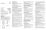
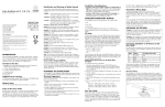
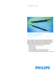
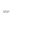
i n s t r u c t i o n s
The scope of this document is to explain in the steps necessary to install
iColor Accent Powercore and assure peak performance. Its intended use is for
reference only, by persons who are fully qualified. This document should never
be considered a substitute for any provision of a regulation or state and / or
local code.
Identification and Warnings of Safety Hazards
Philips Color Kinetics
3 Burlington Woods Drive
Burlington, Massachusetts 01803 USA
Tel 888.Full.RGB
Tel 617.423.9999
Fax 617.423.9998
www.colorkinetics.com
Item # 123-000010-00 (2-foot)
123-000010-01 (4-foot)
123-000010-02 (8-foot)
Copyright © 2009 Philips Solid-State Lighting Solutions, Inc. All rights reserved.
Chromacore, Chromasic, CK, the CK logo, Color Kinetics, the Color Kinetics logo,
ColorBlast, ColorBlaze, ColorBurst, ColorGraze, ColorPlay, ColorReach, DIMand,
EssentialWhite, eW, iColor, iColor Cove, IntelliWhite, iW, iPlayer, Light Without Limits,
Optibin, and Powercore are either registered trademarks or trademarks of Philips
Solid-State Lighting Solutions, Inc. in the United States and / or other countries. All
other brand or product names are trademarks or registered trademarks of their
respective owners.
PUB-000166-00 Rev 05
Specifications subject to change without notice. Refer to www.colorkinetics.com for
the most recent version.
Getting Started
The Philips iColor® Accent Powercore fixture is a direct view indoor /
outdoor linear fixture that can be used to create long ribbons of color to
highlight the outside of buildings or to create low-resolution video displays
in entertainment or retail applications. This guide contains important
information about installing and operating your new iColor Accent
Powercore fixtures safely and accurately.
Included in This Box
• 1 iColor Accent Powercore fixture (either 2-ft (0.46 m),
4-ft (1.22 m), or 8-ft (2.44 m))
• User Guide
Additional Items Needed
•
•
•
•
•
•
•
Philips Data Enabler EO (Item #: 106-000003-06)
50 ft (15.24 m) Leader Cable (Item # 108-000028-01)
1 ft (.30 m) Jumper Cable (Item # 108-000029-03)
2 ft (.60 m) Jumper Cable (Item # 108-000029-06)
5 ft (1.52 m) Jumper Cable (Item # 108-000029-05)
10 ft (3.05 m) Jumper Cable (Item # 108-000029-04
#10 mounting screws (M5) and tools
In accordance with ANSI Z535.4-2002 the following system of identifying
the severity of the hazards associated with the products is used:
“danger” Imminently hazardous situation which, if not avoided, will
result in death or serious injury.
“warning” Potentially hazardous situation which, if not avoided, could
result in death or serious injury.
“caution” Potentially hazardous situation which, if not avoided, may
result in minor or moderate injury or property damage. Also used to alert
against unsafe practices.
ignoring a hazard will void any warranty.
danger: Ensure that main power supply is off before installing, wiring, or
servicing the iColor Accent Powercore.
danger: iColor Accent Powercore must be installed by a qualified
electrician in accordance with NEC and relevant local codes.
warning: Do not attempt to install or use iColor Accent Powercore until
you read and understand the installation instructions and safety labels.
warning: Do not use iColor Accent Powercore if the power cables are
damaged.
warning: As dictated by a Structural Engineer and/or local code, install
safety cables to iColor Accent Powercore fixtures.
warning: When using safety cables, ensure that they comply to the
specifications given in this user guide.
caution: Do not attempt to remove the rubber purge ports located on
the end caps of the fixtures.
caution: iColor Accent Powercore has no serviceable parts. Do not
attempt to open the fixture.
caution: Do not use sharp tools near or on the fixture lens.
caution: Do not hot swap. Ensure that power to the fixture is off before
connecting or disconnecting fixtures.
note: The instructions and precautions set forth in this user guide are not
necessarily all-inclusive, all conceivable, or relevant to all applications as
Color Kinetics cannot anticipate all conceivable or unique situations.
Owner / User Responsibilities
It is the responsibility of the contractor, installer, purchaser, owner, and user
to install, maintain, and operate iColor Accent Powercore in such a manner
as to comply with all state and local laws, ordinances, regulations, and the
American National Standard Institute Safety Code.
Installation Considerations
When creating your installation plan, consider the following:
• Location of Data Enabler EO in relation to the lights. Each Data Enabler
EO supports one leader cable.
• Location of the screw holes on the fixture and method of attaching. The
fixture can be installed using screws suitable for the mounting surface.
• Calculate the number of fixtures per Data Enabler EO. Use the
Configuration Calculator located at www.colorkinetics.com/support
to calculate the number of fixtures you can put on a Data Enabler EO.
This fixtures to Data Enabler EO ratio is determined by the parameters
of your installation. Installation parameters include all or some of the
following: line voltage, fixture type, leader length, and jumper lengths. In
any case, the run of iColor Accent Powercore fixtures cannot exceed 15
fixtures or 100 feet (30.48 m), not including the leader cable.
• Install and wire the Data Enabler EO before installing iColor Accent
Powercore fixtures. Refer to the Data Enabler EO User Guide.
STEPS TO A SUCCESSFUL INSTALLATION
There are two sets of installation steps, depending on whether your iColor
Accent Powercore fixtures will be controlled using Ethernet or DMX.
1. Install the Data Enabler EO.
2. Install the fixtures.
3. Connect the fixtures to Light System Manager (LSM) or Video System
Manager (VSM).
Each of these steps are described below.
Installing the Data Enabler EO (for Ethernet)
Determine the location for the Data Enabler EO. One Data Enabler EO
can support a one leader cable. the run of iColor Accent Powercore
fixtures cannot exceed 15 fixtures or 100 feet (30.48 m), not including the
leader cable.
Things to remember:
• Install the Data Enabler EO according to state and local codes.
• Consult an Electrical Inspector to approve all wiring plans.
Refer to the Data Enabler EO User Guide for complete installation and
wiring instructions. After running power and data to the Data Enabler EO,
you are ready to attach the iColor Accent Powercore fixtures.
Installing the Fixtures (for Ethernet)
A
inches
cm
B
inches
cm
C
inches
cm
D
inches
cm
Fastening
Locations
per Fixture
24
60.96
0.25
0.64
4.88
12.40
14.63
37.16
18.38
46.69
6
4.5
2.0
48
121.92
0.38
0.97
8.06
20.47
16.13
40.97
42.38
107.65
10
9.3
4.2
96
242.84
0.50
1.27
12.06
30.63
24.13
61.29
90.38
229.57
14
18.0
8.6
Weight
lbs.
kg
Use hardware suitable for the mounting surface. (See Figure 1.)
Table 1 lists the dimensions for the different size fixtures.
Figure 1
TOP VIEW
0.25 in (0.64 cm) THRU
(CLEARANCE FOR
#10 FASTENER)
B (SEE TABLE)
that the power source is off before wiring the Data
Enabler EO or connecting fixtures. Failure to do so will result in death and
will void the warranty.
D (SEE TABLE)
note: The
iColor Accent Powercore fixture can be used as a template
when pre-drilled pilot holes are required. Hold the fixture in place and
mark the screw holes.
1. Position the first fixture in a series and attach it with the appropriate
number of #10 mounting screws suitable for the mounting surface.
Ensure that the male connector is in position to receive data and power
from the Leader Cable. (See Figure 2.) Table 1 lists the dimensions for
the different size fixtures.
2. Position the next fixture in the series, matching the male connector end
to the female connector of the previously mounted fixture. Attach the
fixture to the surface. (See Figure 2.) Table 1 lists the dimensions for the
different size fixtures.
The flexible connector cables allow for up to 180º turning radius.
Figure 2
SIDE VIEW
danger: Ensure
planNING the installation
Planning Suggestions
Mount the fixtures by using the mounting holes on each side of the fixture.
The number of mounting holes depends on the size of the fixture (see
Table 1).
When planning iColor Accent Powercore installation, Philips Color Kinetics
suggests doing the following:
• Consult a Structural Engineer to design an installation scheme that is safe
and viable, and an Electrical Inspector to approve all wiring plans.
• Refer to local and state codes for installation compliance.
• Create a Layout Plan drawing.
• Create a Mapping Grid. Use this grid to record serial numbers for easy
reference and addressing.
• Consult Philips Color Kinetics Application Engineering Services as needed,
at [email protected].
Fixture
Size
inches
cm
Installation Steps for Ethernet Control
iColor Accent Powercore fixtures are installed in series. The in-line
connectors allow the fixtures to butt up against one another, providing for
the best visual effects. Jumper cables are available to add space between the
fixtures when needed.
The iColor Accent Powercore installation requires in-depth planning to
ensure timely, successful installation.
Table 1: iColor Accent Powercore Fixture Dimensions
Leader
Cable
Female - to - Male
Connection
First Light in Series
2.03 in (5.16 cm)
i n s t a l l a t i o n
Scope of This Document
2.03 in (5.16 cm)
iColor Accent Powercore
Second Light in Series
TOP VIEW
B (SEE TABLE)
D (SEE TABLE)
0.25 in (0.64 cm) THRU
(CLEARANCE FOR
#10 FASTENER)
C (SEE TABLE)
A (SEE TABLE)
Mounting Base Plate Alignment
3. Continue mounting the fixtures, making power/data connections as you
go, until all lights in the series are mounted.
4. Once all fixtures are mounted and connected, connect the leader cable
from the Data Enabler to the first fixture in the series. Ensure power is
off when making this connection.
5. Insert the terminator into the last fixture of each light series.
6. Repeat Steps 1 through 5 for each Data Enabler in the installation until
all lights are installed. (See Figure 3.)
iColor Accent Powercore Specifications
Figure 4
DMX DATA
Figure 3
a
at
D
En
ab
r
le
EO
DMX
Controller
* PC used for show
authoring and show control.
Ethernet IN
(CAT 5e / RJ45)
WH/ORG
ORG
Data
Enabler
EO
Maximum run length:
The lesser of 15 fixtures
or 100 feet
WH/ORG
ORG
WH/BLUE
BLUE
ETHERNET
100 – 240 VAC
Data Enabler EO
Data
Enabler
EO
DMX OUT
DMX IN
100 – 240 VAC
Data Enabler EO
1. Install the Data Enabler EO.
2. Install the fixtures.
3. Address the fixtures using QuickPlay Pro software.
4. Connect to a Philips Color Kinetics or third party DMX512 controller.
Each of these steps are described below.
Installing the Data Enabler EO (for DMX)
See on page 1.
Installing the Fixtures (for DMX)
See on page 1.
Addressing the Fixtures (for DMX)
note: Serial addressing gives you the option of post-installation addressing
multiple fixtures through a single Data Enabler or multiple Data Enablers
using the recorded serial numbers. Refer to the QuickPlay Pro Addressing
and Configuration Guide.
The iColor Accent Powercore fixtures are pre-addressed to light number
1 at the time of manufacture. Address each fixture with a new light number,
as needed, using QuickPlay Pro.
note: During setup of a DMX installation, the QuickPlay Pro software
addresses the fixtures using an Ethernet connection between the PC and
the Data Enabler EO.
Download the QuickPlay Pro Addressing and Configuration Software and
instructions from www.colorkinetics.com/support/addressing.
1. With power disconnected, connect a single iColor Accent Powercore
fixture or a series of fixtures to a Data Enabler EO.
2. Connect the PC running QuickPlay Pro to the Ethernet Port on the
Data Enabler EO.
3. C
onnect power to the Data Enabler EO.
4. Use QuickPlay Pro to set the light address for each fixture.
Connecting to the DMX512 Controller
For DMX control, connect the iColor Accent Powercore fixtures and the
Data Enabler EO to the Color Kinetics or third party DMX512 controller
as described in the user documentation for the controller. (See Figure 4.)
100 – 240 VAC 50 – 60 Hz
10 W per foot maximum
.01 A per foot maximum
Environmental specifications
temperature range
-4ºF to 122ºF ( -20ºC to 50ºC)
protection ratingIP66
100 – 240 VAC
Installation Steps for DMX Control
ELECTRICAL specifications
Current
WH/ORG
ORG
WH/BLUE
BLUE
DMX IN
DMX OUT
ETHERNET
WH/ORG
ORG
WH/BLUE
BLUE
DMX IN
DMX OUT
ETHERNET
ORG
WH/BLUE
BLUE
WH/ORG
DMX IN
DMX OUT
100 – 240 VAC
Data Enabler EO
Philips Data Enabler EO (Item#106-000003-06)
Philips full line of controllers, including Video System
Manager, Light System Manager, and other DMX512 sources
100 – 240 VAC
Always terminate last
light in series.
Connecting to LSM or VSM (for Ethernet)
For Ethernet control, connect the iColor Accent Powercore fixtures and
the Data Enabler EO to the Light System Manager (LSM) or Video System
Manager (VSM) as described in the LSM or VSM User Guides.
Figure 4 shows the configuration.
caution: Ensure terminator is inserted into last fixture of each series.
Failure to do so may result in minor or moderate injury or property
damage and will void the warranty.
DMX OUT
(CAT 5 / RJ45)
control
power consumption
Maximum Run length:
The lesser of 15 fixtures
or 100 feet (30.48 m)
Terminator
data interface
DMX IN
(CAT 5 / RJ45)
input voltage
ETHERNET
Connectors are gender specific.
Ensure that all lights are installed
with connectors facing the same directions.
Ethernet IN
(CAT 5e / RJ45)
DMX IN
Ethernet IN
(CAT 5e / RJ45)
Maximum run length:
The lesser of 15 fixtures
or 100 feet
ETHERNET
Ethernet
Switch
WH/BLUE
COMMUNICATION specifications
BLUE
PC*
DMX OUT
Light
Video
System - or - System
Engine
Engine
50-foot (15.24 m)
leader cable
to first light in series
Female-to-Male
connection
16.7 million additive RGB colors; continuously variable
intensity output range
output50-100 lumens (estimated)
sourceChip-on-board RGB LEDs
visibility range
250º x 180º
housing
Sealed plastic and extruded aluminum
weight
2-ft (0.61 m) - 4.5 lbs (2.0 kg)
4-ft (1.22 m) - 9.3 lbs (4.2 kg)
8-ft (2.44 m) - 18.0 lbs (8.2 kg)
connectors
Over-molded, integral male/female connectors
listings UL / cUL, CE
color range
ETHERNET DATA
DMX IN
Terminator
Temperature Monitoring
For protection from extreme temperatures, the iColor Accent Powercore has been
designed with a temperature monitoring feature. If operating temperatures rise to
an unsafe level, a compensation circuit is triggered and the iColor Accent Powercore
operation is interrupted causing the lights to turn dull red.
To prevent additional power shut-downs, determine the cause of the overheating and
correct the problem. Power-cycle the system to return to full intensity.
LED Source Life
In traditional lamp sources, lifetime is defined as the point at which 50% of the lamps fail.
This is also termed Mean Time Between Failure (MTBF). LEDs are semiconductor devices
and have a much longer MTBF than conventional sources. However, MTBF is not the only
consideration in determining useful life. Philips Color Kinetics uses the concept of useful
light output for rating source lifetimes. Like traditional sources, LED output degrades over
time (lumen depreciation) and this is the metric for SSL lifetime.
LED lumen depreciation is affected by numerous environmental conditions such as
ambient temperature, humidity, and ventilation. Lumen depreciation is also affected by
means of control, thermal management, current levels, and a host of other electrical design
considerations. Philips Color Kinetics systems are expertly engineered to optimize LED
life when used under normal operating conditions. Lumen depreciation information is
based on LED manufacturers’ source life data as well as other third party testing. Low
temperatures and controlled effects have a beneficial effect on lumen depreciation. Overall
system lifetime could vary substantially based on usage and the environment in which the
system is installed.
Temperature and effects will affect lifetime. Philips Color Kinetics rates product lifetime
using lumen depreciation to 50% of original light output. When the fixture is running at
room temperature using a color wash effect, the lifetime is in the range of 30,000-50,000
hours. This is based on LED manufacturers’ test data. For more detailed information on
source life, please see www.colorkinetics.com/lifetime.