1
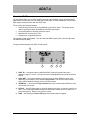
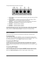
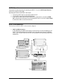
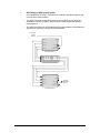
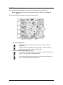
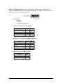
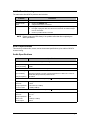
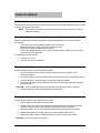
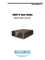
SoundPals™
ADAT-4 User Guide
ADAT-to-AES converter
Printing History
SoundPals™ ADAT-4 ADAT-to-AES converter
Rev. N/C
March 2007
Printed in U.S.A.
Part Number 08-2054-00
The information contained in this guide is subject to change without notice or obligation.
Copyrights and Trademarks
© 2005 GRAHAM-PATTEN SYSTEMS, INC.
Contents of this publication may not be reproduced in any form without the written permission of Graham-Patten.
Reproduction or reverse engineering of copyrighted software is prohibited.
FCC Compliance
This equipment has been tested and found to comply with the limits for a Class A digital device pursuant to Part 15
of the FCC Rules. These limits are designed to provide reasonable protection against harmful interference when the
equipment is operated in a commercial environment. This equipment generates, uses, and can radiate radio
frequency energy and, if not installed and used in accordance with the instruction manual, may cause harmful
interference to radio communications. Operation of this equipment in a residential area is likely to cause harmful
interference in which case the user will be required to correct the interference at your own expense.
Warranty Statement
Graham-Patten warrants that the equipment it manufactures is free from defects in workmanship and materials and
meets applicable published specifications. Equipment that has been operated within published ratings and has not
been subjected to abuse or modification, and which fails because of such defects, will be replaced or repaired at the
Company’s discretion if it is returned, freight prepaid, to Graham-Patten within seven years of receipt.
This warranty supersedes all other Warranties, express or implied. Graham-Patten is not liable for any
consequential damages.
Company Address
GRAHAM-PATTEN SYSTEMS, INC.
119 East McKnight Way, Unit A
Grass Valley, California 95949
Telephone: (888) 622-4747, (530) 477-2984
Fax: (530) 477-2986
e-mail: [email protected]
World Wide Web: www.gpsys.com
Graham-Patten is a division of
Table of Contents
Table of Contents
ii
Introduction
1
What are SoundPals?.............................................................................................................. 1
Documentation Conventions.................................................................................................... 1
Signals and Values .................................................................................................................. 1
Warnings.................................................................................................................................. 1
Unpacking and Inspection ....................................................................................................... 2
Power Supply Note .................................................................................................................. 2
ADAT-4
3
About the ADAT-4.................................................................................................................... 3
ADAT-4 Installation.................................................................................................................. 4
Connecting Power ............................................................................................................. 4
Connecting the ADAT Input .............................................................................................. 4
Connecting the ADAT Outputs.......................................................................................... 4
ADAT-4 Operation ................................................................................................................... 5
ADAT-4 Interconnection .......................................................................................................... 5
ADAT-to-AES Conversion................................................................................................. 5
ADAT Bridge to AES Routing System............................................................................... 6
ADAT-4 Internal Jumpers ........................................................................................................ 7
ADAT-4 Troubleshooting ......................................................................................................... 9
ADAT-4 Specifications............................................................................................................. 9
Audio Specifications .......................................................................................................... 9
Environmental Specifications and Dimensions ............................................................... 10
Channel Routing.............................................................................................................. 10
Inside the Module ........................................................................................... 11
In This Section ....................................................................................................................... 11
Before You Begin................................................................................................................... 11
Opening the Module .............................................................................................................. 11
Closing the Module ................................................................................................................ 11
External Power................................................................................................ 12
About Power Supplies ........................................................................................................... 12
CE Compliance ...................................................................................................................... 12
Portable Power Sources ........................................................................................................ 12
Power Supply Specifications ................................................................................................. 12
Power Supply Sources .......................................................................................................... 12
ii • Table of Contents
ADAT-4 User Guide
Introduction
What are SoundPals?
Each Graham-Patten SoundPals module is essentially a digital audio building block that can be
used independently, or interconnected to perform more advanced mixing and audio processing
functions.
SoundPals can be used in both standalone and system configurations:
•
In a “standalone” configuration, each SoundPals module is designed to perform a specific
audio processing function such as ADAT-to-Analog conversion. In this way, each module
functions as a perfect low-cost adjunct to larger mixing consoles (such as the GrahamPatten D/ESAM series) — for single-purpose processing tasks.
•
In a “system” configuration, SoundPals can be linked to form more comprehensive digital
audio tools. For field recording, studio applications, and workstation applications,
SoundPals can be used to seamlessly perform functions that would otherwise require
extensive peripheral gear. Best of all, SoundPals “systems” can be re-configured quickly
and easily — to suit your changing audio production requirements.
All SoundPals modules are extremely compact, rugged, and identical in size for ease of
installation, interconnection, and use. In addition, SoundPals support AES3id. This allows
longer, more robust AES signal distribution using standard coaxial cable. Error free distances of
1000 feet can be attained using inexpensive coaxial cables.
Documentation Conventions
The following documentation conventions are used in this guide:
•
Buttons, knobs, connectors, and switches are indicated in bold-faced capital letters. For
example:
Adjust the left GAIN TRIM to …
•
Primary sections are listed in bold text, with a line above:
Primary Section
•
Secondary sections are listed in bold text, with no line:
Secondary Section
Signals and Values
Note the following important information regarding audio signal level:
•
•
AES3 = Balanced output with 2 channels of digital audio (left and right)
AES3id = Unbalanced output with 2 channels of digital audio (left and right)
Warnings
Please observe the following important warnings:
•
•
•
Heed all warnings on the unit and in the instructions.
Do not use this product in or near water.
Route power cords and other cables so that they are not likely to be damaged.
Disconnect power before cleaning. Do not use liquid or aerosol cleaners; use only a
damp cloth.
ADAT-4 User Guide
Page 1
Unpacking and Inspection
When you receive your SoundPals modules, inspect the cartons for signs of damage. Contact
your dealer and the shipper immediately if you suspect any damage has occurred during
shipping. Check the contents of each box to be sure that all parts are included. If any items are
missing, contact your dealer immediately.
Power Supply Note
SoundPals are delivered with a power connector only. A separate power supply must be
obtained. Graham-Patten offers several power solutions for both domestic and international
customers. Refer to “External Power” for detailed power specifications for users who wish to
configure their own power source, rather than purchase one from Graham-Patten.
Page 2
ADAT-4 User Guide
ADAT-4
About the ADAT-4
The SoundPals ADAT-4 is an ADAT-to-AES converter that separates a single 8-channel ADAT
data stream on optical fiber into four AES output audio pairs, on either balanced or coaxial cable.
AES outputs are synchronous with the ADAT input.
The unit offers the following features:
•
•
•
•
Synchronizing connector for a silent AES3id or word clock output. This output can be
used to synchronize other SoundPals to the ADAT data stream.
Front panel switch for selecting reference output
Optional rack mounting tray (1 RU)
Compact size, rugged construction
Two product models are available: The “A” model has AES3 outputs (XLR), and the “B” model
has AES3id outputs (BNC).
The figure below illustrates the ADAT-4’s front panel:
ADAT-4
ADAT-4
1
AES
I/P ERR
ADAT IN
SYNC OUT
WCLK
2
3
PWR
4
5
1) ADAT IN — the optical input is a standard ADAT signal using plastic fiber with a
maximum range of 1 meter. The input must have a sampling frequency between 30 and
50 KHz.
2) SYNC OUT — the synchronization output can be set to either AES3id or word clock,
depending on the position of the adjacent Sync Switch. The AES3id output uses the
same channel status bit settings as the main AES outputs.
3) AES/WCLK — the two-position Sync Switch allows you to select either AES3id or word
clock as the sync output.
4) I/P ERR — this LED lights when no signal is applied to the input, or when the signal is not
valid. A non-valid signal exhibits errors such as format violations, bit errors, low level, or
incorrect frequency. When lit, the output is muted.
5) PWR — the large green Power LED lights when system power is applied.
ADAT-4 User Guide
Page 3
The figure below illustrates the ADAT-4’s rear panel:
2
3
4
5
6
AES OUT 1
AES OUT 2
AES OUT 3
AES OUT 4
MADE IN THE USA
1
MODEL A
+6V
200mA
1) ADAT-4 Model— the “A” model has AES3 outputs (XLR), and the “B” model has AES3id
outputs (BNC).
2) Power Connector — accepts the power jack from the 6 VDC power supply. Refer to
“External Power” for more information regarding external power.
3) AES OUT 1 — output #1 is standard AES audio, either AES3 (XLR) for the A model or
AES3id (BNC) for the B model. The output is locked to the ADAT input.
4) AES OUT 2 — identical in function to output #1.
5) AES OUT 3 — identical in function to output #1.
6) AES OUT 4 — identical in function to output #1.
An internal jumper allows the outputs to have 20 or 24 active bits. In 20-bit mode, each output’s
auxiliary data bits will be set to zeros. Output channel status bits will reflect the 20/24-bit mode
setting. Refer to the “ADAT-4 Internal Jumpers” for instructions on all jumper settings.
ADAT-4 Installation
This section provides instructions for connecting power, digital inputs. and digital outputs.
Connecting Power
Plug a 6 VDC power supply (rated at 200 mA or greater) into the appropriate voltage outlet for
your specific country, and connect the end of the cord into the ADAT-4 jack marked +6V. Secure
the locking ring finger tight. The green PWR LED lights when power is applied.
Connecting the ADAT Input
The ADAT optical input includes eight audio signals with synchronization words, auxiliary data
bits (currently all zeros) and clock extraction bits to conform to the ADAT format. Using an
approved 1-meter (or less) ADAT cable, connect the desired ADAT source to the ADAT-4’s input
connector.
Connecting AES Outputs
Connect the digital audio output from one of the four AES OUT connectors, and route it to the
input of the desired destination device. Repeat the procedure for all digital outputs as required.
Refer to the “ADAT-4 Specifications” section for a table of ADAT-4 channel routing.
Page 4
ADAT-4 User Guide
ADAT-4 Operation
This section includes instructions for operating the ADAT-4. See the “ADAT-4 Specifications”
section for a channel routing table.
Operating procedures for the ADAT-4 are simple:
•
•
•
Connect the ADAT input from the desired ADAT source.
Connect AES outputs to the desired destinations.
If you want to use the ADAT-4 as the reference for another device, connect the SYNC
OUT connector to the reference input of the destination device, and use the Sync Switch
to select either AES or word clock reference.
ADAT-4 Interconnection
This section provides two ADAT-4 interconnection diagrams.
•
ADAT-to-AES Conversion
In this application, the ADAT optical cable is connected from an audio workstation to the
ADAT-4. The AES outputs from the ADAT-4 are connected to the inputs of a D/ESAM
mixer, a DAT recorder, and also to a DAC-24 for purposes of driving analog outputs and
headphones.
PW R
A E S In
A E S In
R T rim
L T rim
R ig h t O u t
V o lu m e
L e ft O u t
H eadphones
S o u n d P a ls D A C -2 4
W o rk s ta tio n
AES O ut 1
S te re o
H eadphones
PW R
A n a lo g O u t (L )
A n a lo g O u t (R )
A ES O ut 2
AES O ut 3
AES O ut 4
A D A T In
AES O ut /
W o rd C lo c k O u t
D A T R e c o rd e r / P la y e r
S o u n d P a ls A D A T -4
D ig ita l
In p u ts
D /E S A M
M ix e r
ADAT-4 User Guide
Page 5
•
ADAT Bridge to AES Routing System
In this application, the ADAT-3 and ADAT-4 combine to provide a bridge in and
out of an AES routing switcher.
~
The ADAT-4 accepts an optical input from a source ADAT device (such as a
workstation or ADAT recorder), and provides four AES outputs that feed the
routing switcher.
~
The ADAT-3 accepts four AES inputs from the routing switcher, and provides an
optical ADAT output for routing to ADAT destinations.
From ADAT
Source
Devices
PWR
AES Out 1
AES Out 2
AES Out 3
AES Out 4
ADAT In
AES Out /
Word Clock Out
SoundPals ADAT-4
Facility AES Routing Switcher
PWR
AES In 1
Control
AES In 2
AES In 3
AES In 4
ADAT Out
AES In /
Word Clock In
To ADAT
Destination
Devices
SoundPals ADAT-3
Page 6
ADAT-4 User Guide
ADAT-4 Internal Jumpers
This section provides information about the ADAT-4’s internal jumpers and switches.
NOTE
For detailed instructions on opening and closing the ADAT-4, see “Inside the
Module.”
The figure below shows the ADAT-4’s internal jumper locations:
GRAHAM-PATTEN SYSTEMS
GRASS VALLEY, CALIFORNIA
Made in U.S.A.
ADAT-4
04-0236-
J2
J5
SW2
Word Clock
Polarity Jumper
•
20/24 Bit
Jumper
J2 is the 20/24 Bit jumper.
1
2
1
2
•
Status
Dip Switch
–
To set all 4 channels to 24 bits, install the jumper. This is the default
configuration.
–
To set all 4 channels to 20 bits, remove the jumper. In 20-bit mode, any
auxiliary data on the AES inputs will be discarded.
J5 is the Word Clock Input Polarity jumper.
1
–
To leave work clock input reference normal, strap the jumper between pins
1 and 2. The rising edge is used as reference.
–
To invert the work clock input reference, strap the jumper between pins 2
and 3. The falling edge is used as reference.
2
3
1
2
3
ADAT-4 User Guide
Page 7
SW2 is the Status Dip Switch which is used to set the channel status on all AES outputs,
including the SYNC output (provided that the Sync Switch is set to AES). The switch is an eightposition DIP, of which five switches are active.
1 (closed) top position
1 2 3 4 5 6 7 8
0 (open) bottom position
OPEN
For all switches:
~
~
~
•
0 is open
1 is closed
The default setting is all 0’s
Switches 1 and 2 determine the Emphasis.
Function
•
0
0
None
1
0
50/15uS
0
1
J.17
1
1
Switches 3 and 4 determine the Sample Frequency.
Not Indicated
SW3
SW4
0
0
48 kHz
0
1
44.1 KHz
1
0
32 KHz
1
1
Switch 5 determines the Stereo Mode.
Function
Page 8
SW2
Not Indicated
Function
•
SW1
SW5
Not Indicated
0
Stereo
1
ADAT-4 User Guide
ADAT-4 Troubleshooting
The table below lists ADAT-4 problems and solutions.
Problem
No output.
Outputs are all
silent.
Input ERROR.
Procedure
•
•
•
•
•
•
NOTE
Check Power by Green LED.
Check Input ERROR LED.
Verify that the source is not silent.
Unplug the fiber cable and check for visible red light (this is not harmful).
If no light, unplug the cable from the source and check for visible red light
from the transmitter.
Check for possible break in the fiber.
Please contact the GPS factory if the problem still exists after completing the
above procedures.
ADAT-4 Specifications
This section provides audio, remote, and environmental specifications, plus a table of ADAT-4
channel routing.
Audio Specifications
Parameter
Specification
Dynamic Range
24-bit processing
20-bit processing
138 dB
120 dB
ADAT Input
Peak wavelength
Input sensitivity
Sample frequency
660 nm
Adequate sensitivity to receive a signal transmitted at -17 dBm over 1 meter of
plastic fiber (Sharp GP1C321) without errors.
30–50 KHz
A Model — AES3 Outputs (110Ω Termination)
Amplitude
Rise time
Output impedance
Common mode
2–7 V p-p
5–30 ns
110Ω ±20% (0.1–6 MHz)
<-30 dB (0–6 MHz)
B Model — AES3id Outputs (75Ω Termination)
Amplitude
Rise time
Output impedance
Return loss
DC on output
ADAT-4 User Guide
1 ±0.2 V p-p
37 ±7 ns
75Ω
>15 dB (0.1–6 MHz)
<50 mV
Page 9
Audio Specifications (continued)
AES3ID Synchronization Output
Amplitude
Rise time
Output impedance
1 ±0.2 V p-p
37 ±7 ns
75Ω
>15 dB (0.1–6 MHz)
<50 mV
Return loss
DC on output
Word Clock Synchronization Output
Amplitude
VLO <0.5 V at IOUT = -5 mA
Waveform
Phasing
Square-wave at Fs
+ edge coincident with audio sampling instant. Use jumper J5 to invert.
VHI >4.5V at IOUT = 5 mA
Options
RT-2, 1RU rack tray for mounting up to 3 units
Power supplies:
PSU-1, 90-260V 50/60Hz in-line power supply with detachable IEC power cord
All specifications listed above subject to change without notice.
NOTE
Environmental Specifications and Dimensions
Parameter
Specification
Dimensions
(less connectors)
Power
Operating Temp
5.2W x 1.62H x 6.625D
13.2 x 4.1 x 16.8 cm
<200 mA @ 6 Vdc
Operating
Humidity
10 – 90% RH non-condensing
10 – 50 °C
Channel Routing
The table below lists ADAT-to-digital channel routing in the ADAT-4:
ADAT Input Track
Page 10
AES Output
1, 2
→
1
3, 4
→
2
5, 6
→
3
7, 8
→
4
ADAT-4 User Guide
Inside the Module
In This Section
This section provides instructions for opening and closing the SoundPals SDDM-8 module to gain
access to the internal circuit board.
NOTE
The internal circuit board should only be removed from the module if you want to
change the jumpers.
Before You Begin
Check the following items before opening the module and attempting to remove the internal
circuit board:
If required, remove the SoundPals module from the rack tray.
Disconnect the power supply from the front of the product.
Disconnect all input, output and control cables.
Perform the remaining steps only in a static free environment. Make sure that you and
the product are both grounded.
The following tools are required:
•
•
#2 Phillips screwdriver
9/16 box wrench (or end wrench)
Opening The Module
Use the following steps to open a SoundPals module:
1. On the rear panel, remove the four Phillips screws from the four corners of the
SoundPals module.
2. On the front panel, remove all Philips XLR mounting screws from the SoundPals module.
3. On the front panel, remove the BNC nut and associated lock washer.
4. Pulling the rear panel, carefully draw the internal circuit board and rear panel assembly
from the housing.
CAUTION
Keep the case horizontal so that the BNC bushing stays with the connector.
5. Set the housing and all mounting hardware in a safe place.
Closing The Module
Use the following steps to close a SoundPals module:
1. Ensure that the product label is on the bottom.
2. Carefully slide the internal circuit board and rear panel assembly through the housing.
Keep the case horizontal so that the BNC bushing stays with the connector.
3. Replace the BNC nut and associated lock washer on the front panel of the module.
4. Replace all Phillips XLR mounting screws on the front panel of the module.
5. Replace and tighten the four Phillips screws on the rear corners of the module.
CAUTION
Do not over tighten the screws.
ADAT-4 User Guide
Page 11
External Power
About Power Supplies
An external power supply conforming to the specifications listed in the following “Power Supply
Specifications” section must be used to guarantee that published SoundPals performance
figures are met. Any power supply meeting these specifications will supply adequate power for a
single SoundPals module. Although the specification is written for power supplies running from
AC line inputs, DC (battery) sources may be used if they meet all of the listed requirements.
CE Compliance
For CE compliance, the power supply that you use must comply with the following requirements:
•
•
•
•
Low Voltage Directive 73/23/EEC
EMC Directive 89/336/EEC
EMC Directive 93/68/EEC
The connector locking ring must be tight.
Portable Power Sources
For portable SoundPals power sources, sealed lead-acid, nickel cadmium or alkaline primary
batteries may be used. However, the maximum voltage must not exceed 8.6 volts, and a
minimum of 5.6 volts is required for normal operation. Maximum current drain will be 215mA.
Power Supply Specifications
The following specifications must be met over all anticipated operating conditions including AC
power line range, temperature range, etc.
Parameter
Output voltage
Ripple voltage
Specification
5.6 V minimum (measured at trough of ripple) at 215 mA constant current.
8.6 V maximum (measured at peak of ripple) at 140 mA constant current.
2 V p-p at 700 mA constant current.
400 mV p-p at 700 mA constant current with external 2200 µF capacitor.
Connector
Switchcraft 761K with center positive, sleeve negative.
Power Supply Sources
In addition to the GPS-supplied universal power supply, the following power supplies meet the
SoundPals requirements:
Company
Stancor
Stancor
Elpac
Page 12
Model
Note
STA-4860
STAF-0797F
MI2007
120V AC, 60 Hz
220V AC, 50 Hz with European wall plug (CE compliant).
95-250V AC, 47-63 Hz with IEC inlet (line cord required). Will power up to six
units (CE compliant).
ADAT-4 User Guide