1
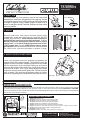
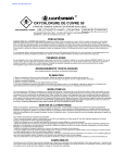
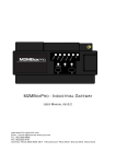
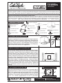
INSTRUCTION SHEET
TA SERIES
TOP-ACCESS
READ AND UNDERSTAND THESE INSTRUCTIONS BEFORE INSTALLING FIXTURE
This fixture is intended for installation in accordance with the National Electrical Code and local regulations. To ensure full compliance with local
codes and regulations, check with your local electrical inspector before installation. To prevent electrical shock, turn off electricity at fuse box
before proceeding. Retain these instructions for maintenance reference. TECHINCAL SUPPORT (800) 863-1184 8am-4pm CDT M-F
INSTALLATION PROCEDURE FOR PHANTOM TOP–ACCESS FIXTURE
REMOVE THE FIXTURE AND MOUNTING HARDWARE FROM THE CARTON. IDENTIFY ALL PARTS AND READ THE FOLLOWING
ASSEMBLY INSTRUCTIONS BEFORE PROCEEDING WITH THE INSTALLATION. THE INSTRUCTIONS ARE IN A STEP BY STEP SEQUENCE
FOR CORRECT AND EASY ASSEMBLY. PLEASE FOLLOW THE SEQUENCE! SAVE THE CARTON AND ALL PACKING MATERIALS UNTIL
JOB IS COMPLETE. SAVE THESE INSTRUCTIONS FOR MAINTENANCE REFERENCE! U.S.. PATENT PENDING
(1) Projector Supplement
1. COMPONENTS CHECK LIST
(1) Mounting Cradle
(3) Black Knobs
(1) Allen Wrench
(2) Condensing Lenses
(3) Focal Lenses
(3) Sets of Shutters
(1) Housing
(1) Projector
(1) MR 16 Lamp (EYC)
(1) Rotating Ring
(1) Junction Box
(1) Heat shield
(1) Glare shield
(1) Breakaway Cone
(1) Custom Trim
(1) (Optional) Slide
12"
2. DETERMINE MOUNTING LOCATION
A projector supplement has been provided to illustrate projector
performance, location and beam configurations. Determine the
exact location and verify adequate space between rafters and
depth of ceiling cavity to accommodate housing before
proceeding. Because this a custom installation a second person
might be required to assist in the application.
12"
9"
3. INSTALL HOUSING / ATTIC ACCESS ONLY
Once you have determined the best location for the projector,
go into the attic to see if you have the area necessary to install
the housing. Using a Philips head screwdriver make a hole in
the best location for the projector trim. After making your hole
go to the floor below and check to see if it is in the correct
location. Keep the hole that you made with the screwdriver in
the center of the elongated hole in the heat shield. Adjust the
housing forward or backward as needed. The mounting arms
are turned inwards for shipping purposes, rotate the arms to
the outward position so that you will have a better drilling
position for your mounting screws. Extend the mounting arms
to fit snuggly between joists and screw into place. Tighten the
three hex head screws to anchor the arms and secure to
housing.
Joist
4. CUT OPENING FOR CUSTOM TRIM
Using the heat shield and a key hole saw, cut around edge of
appropriate knock out hole as clean as possible. Elongated
hole is for angle aiming and the center hole is for vertical
aiming. It is OK if the housing and projector are not centered
on painting. The projector works perfectly at angles off center
of art. For vertical appplications no trim is provided.
R
C
US
73355
ETL LISTED, LUMINAIRES TO UL STD 1598
& TRACK LIGHTING TO UL STD 1574
Art
Heat Shield
Joist
ILLUMINATIONS
Lighting Design
607 Durham Drive
Houston, Texas 77007-5316
Tel: 713-863-1133 / Fax: 713-863-0044
INSTRUCTION SHEET
TA SERIES
TOP-ACCESS
5. INSERT TRIM
Once you have cut your opening, remove the heat shield
temporarily to install your elongated trim into opening. Pull the
elongated trim back up to ceiling and bend the flanges down
for a tight fit against ceiling. Staple flanges to sheet rock to
secure. Install glare shield if desired. Replace the heat shield
back into position.
7. WIRE IN
Remove metal cover from junction box and inspect wiring
compartment. Install strain relief device(s) and bring SUPPLY
WIRES into junction box. Allow adequate slack in wire(s) to
pull J-BOX into housing for servicing transformer. Connect
WHITE transformer and thermal protector lead to neutral
supply lead. Connect BLACK thermal protector lead to HOT
(120V) supply lead. Connect GREEN fixture wire to supply
ground lead. Place all electrical connections in J-BOX and close
the J-BOX cover. (See wiring diagram on bottom of page)
6. INSTALL PROJECTOR AND CRADLE
Lower your projector cone into opening and position the
projector back at the desired angle. The cradle fits over the
projector to hold it into place. Install the projector into the cradle
with the three holes on the projector facing up and secure
using one black knob to the center hole. Insert pivot pegs into
pivot holes on cradle. This is your aiming angle pivot. Angle
projector to correct position and tighten the 2 black knobs on
sides of cradle. See projector supplement sheet for further
instructions regarding lens combinations and projector set up.
Pivot Pegs
DIMMING NOTES
This fixture contains an electronic transformer that may require the use of a special dimmer.
LAMPING AND TRANSFORMER NOTES
Socket manufacturers have suggested that sockets may fail after 3 to 6 lamp changes. If this occurs the socket can be replaced
by disconnecting the fixture lead wires and replacing it with a new socket procured through PHANTOM™ LIGHTING.
In the event of a short circuit or overload, the transformer will automatically shut down the output. The transformer will automatically
reset as soon as the short is corrected.
SUPPLY 120V
WHITE
GROUND WIRE
STRAIN RELIEF
DEVICE
RED
12 VOLT
LEADS
BLACK
BLUE
BLACK
WHITE
WHITE
75 WATT
ELECTRONIC
TRANSFORMER
THERMAL
PROTECTOR
R
C
US
73355
ETL LISTED, LUMINAIRES TO UL STD 1598
& TRACK LIGHTING TO UL STD 1574
TRANSFORMER REPLACEMENT
1. Make sure power is off.
2. Remove ceiling trim, projector and mounting cradle.
3. Remove junction box and disconnect supply wires.
4. Remove transformer from junction box and replace.
5. Splice transformer red leads to white socket leads.
6. Splice transformer black lead to thermal protector blue lead.
7. Splice transformer and thermal protector white leads to supply common leads.
8. Splice thermal protector black lead to supply black lead.
9. Replace junction box cover.
10. Reinstall projector mounting cradle, projector and ceiling trim.
ILLUMINATIONS
Lighting Design
607 Durham Drive
Houston, Texas 77007-5316
Tel: 713-863-1133 / Fax: 713-863-0044