1
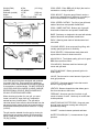
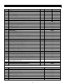
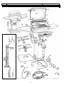
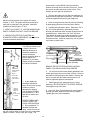
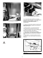
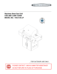
R
Models K-30 and K-40
Gas Grill
click here for Legacy Series
ASSEMBLY, OPERATING
& MAINTENANCE INSTRUCTIONS
(SHOWN WITH OPTIONAL
SIDE BURNER AND INFRA-BROIL KIT)
PACIFIC GAS SPECIALTIES CORPORATION
P.O. BOX 16097, IRVINE, CALIFORNIA 92623
Phone (949) 757-7723 FAX (949) 474-5559
Please note: We have made our catalogs, specification sheets, and other materials relating to our line of outdoor
cooking products as comprehensive and accurate as possible. We are constantly trying to improve all aspects of our
products and therefore, reserve the right to make changes anytime, without notice. Because product improvements
may have been made since the time our materials were printed, please check with your Authorized PGS Dealer or
Distributor, if you have any specific questions concerning our products. PGS is dedicated to producing the finest
Revised 5/1/2003
leisure gas appliances for the home.
TABLE OF CONTENTS
Safety Responsibilities, Warning Symbol .................................................................................................Page 2
Grill Model Identification (Location of Serial Number) ..............................................................................Page 3
Very Important Safety Tips & Warnings ..............................................................................................Page 4 - 5
Liquid Propane Gas Safety, Connections, Handling and Storage.....................................................Page 6 - 87
Natural Gas Pressure Requirements........................................................................................................Page 9
Definition of Key Terms ............................................................................................................................Page 9
Required Tools and Nuts, Bolts and Fasteners Part Numbers...............................................................Page 10
Drawings of Nuts, Bolts, and Fasteners .................................................................................................Page 10
Part Numbers & Descriptions .................................................................................................................Page 11
Parts Breakdown .................................................................................................................................. Pages 12
Check List of Grill Box Contents.............................................................................................................Page 13
Permanent Post Installation ..........................................................................................................Pages 14 - 15
Patio Base/Patio Cart to Grill Head Assembly...............................................................................Pages 15 - 16
Orifice Engagement................................................................................................................................Page 16
Side Shelf Installation.............................................................................................................................Page 17
Finish Assembly .....................................................................................................................................Page 17
Connecting Your Gas Supply .................................................................................................................Page 18
Lighting Your Grill / If Burner Fails to Light.............................................................................................Page 20
Periodic Cleaning ...................................................................................................................................Page 20
Flashback (Spider Fires) ........................................................................................................................Page 21
Electrode Adjustment .............................................................................................................................Page 22
Flare Ups ................................................................................................................................................Page 22
Grease Tray Clean Out ..........................................................................................................................Page 22
Gas Grill Conversion ..............................................................................................................................Page 22
Helpful Hints ...........................................................................................................................................Page 23
Flame Adjustment ..................................................................................................................................Page 24
Trouble Shooting ........................................................................ See PGS Web Site for Troubleshooting Guide
PGS Accessories ...................................................................................................................................Page 25
2
Please consult your authorized PGS dealer if you have
any questions concerning assembly, installation or
operation of your grill.
SPECIAL ATTENTION:
THIS SYMBOL NOTES SAFETY RELATED
ITEMS OR PRODUCT WARNINGS
IT IS YOUR RESPONSIBILITY TO:
ASSEMBLE, INSTALL, LEAK CHECK, CARE AND
OPERATE YOUR GAS GRILL. SAVE THESE
INSTRUCTIONS FOR FUTURE REFERENCE.
FOR YOUR SAFETY IF YOU SMELL GAS:
1. SHUT OFF GAS TO THE APPLIANCE.
2. EXTINGUISH ANY OPEN FLAME.
3. OPEN LID.
4. IF ODOR CONTINUES, IMMEDIATELY
CALL YOUR GAS SUPPLIER.
The display of a test agency certification seal on the
product label indicates that the unit is constructed
according to the certified testing agency.
MODEL IDENTIFICATION
Your PGS Grill is identified by a model number and the
serial number stamped on the stainless steel collar
box located under the control panel and included with
your grill head. TAKE THE TIME NOW TO RECORD
THE MODEL AND SERIAL NUMBER (located on the
collar box) OF YOUR GRILL IN THE SPACE
PROVIDED BELOW. Always use both the model
number and the serial number when calling or writing
PACIFIC GAS SPECIALTIES about your grill. We can
be reached at: PO Box 16097, Irvine, CA 92623-6097
(949) 757-7723 FAX (949) 474-5559. Email:
[email protected].
THIS GAS GRILL IS DESIGNED FOR OUTDOOR
USE ONLY
FOR YOUR SAFETY:
DO NOT STORE OR USE GASOLINE OR OTHER
FLAMMABLE VAPOR AND LIQUIDS IN THE
VICINITY OF THIS APPLIANCE.
THIS GRILL IS NOT INTENDED FOR USE ON A
BOAT/HOUSE BOAT OR RECREATION VEHICLE
PLEASE RETAIN INSTRUCTIONS FOR FUTURE
REFERENCE, AND RETURN THE OWNERS
REGISTRATION CARD IMMEDIATELY. RETURN
OF WARRANTY CARD INSURES WARRANTY
REGISTRATION. MAINTAINING YOUR SALES
RECEIPT WILL EXPEDITE WARRANTY CLAIMS.
STORE THE LP GAS (PROPANE) CYLINDER
OUTDOORS IN A WELL-VENTILATED SPACE.
DO NOT STORE A PROPANE GAS CYLINDER IN
DIRECT SUNLIGHT. DO NOT STORE EXTRA
CYLINDERS IN CART OR NEAR GRILL. DO NOT
STORE THE PROPANE CYLINDER ON IT S SIDE.
DATE PURCHASE: __________________________
Teflon tape or pipe joint compound will be
required on all steel pipe connections.
Never use a sealer when your connection
is brass to brass. Brass to brass is self-sealing.
Using a sealant on a brass to brass connection
may cause a leak!
DEALERSHIP: ______________________________
CITY, STATE: ______________________________
MODEL NUMBER:___________________________
TYPE OF GAS: NATURAL GAS___PROPANE_____
SERIAL NUMBER ___________________________
The grill itself is partially assembled, with the burner,
venturi, ignitor, collector box, and ignitor lead wire
installed. Take your time in assembly. Please read
instructions thoroughly before starting assembly.
The grill must be located no closer than 30" from
any combustible surface above, behind or
to the sides. The grill should not be
located under overhead-unprotected
combustible materials.
This manual is based on information available when
the manual was printed. Continued improvements in
design could cause changes in the grill that may or
may not be included herein.
3
VERY IMPORTANT SAFETY TIPS AND WARNINGS
PGS is most concerned about the safe use of our product. The following two pages are a summarization of the safety
tips found throughout this manual. Please take the time to review them, as they are critical in the enjoyable use of
your grill. Improper assembly, neglect, or insufficient care of your PGS gas grill may result in serious bodily injury
and/or property damage.
GIVE THIS SYMBOL SPECIAL ATTENTION THROUGHOUT THIS MANUAL. IT NOTES SAFETY
RELATED ITEMS OR PRODUCT WARNINGS
Our grills are tested in accordance with ANSI Z21.58a-1999*CGA 1.6a-M99 Standard for Outdoor Gas Cooking
Appliances. Check your local building codes for the proper methods of installation. In the absence of local codes,
this grill should be installed in compliance with the National Fuel Code No. Z223.1-1995 and the National Electrical
Code ANSI/NFPA No. 70-1995. GAS GRILLS ARE NOT AGA DESIGN CERTIFIED OR RECOMMENDED FOR
USE ON RECREATIONAL VEHICLES, PORTABLE TRAILERS, BOATS/HOUSE BOATS, OR ANY OTHER
MOVING INSTALLATION.
• California Proposition 65 Warning: The burning of gas cooking fuel generates some by-products which are on the
list of substances and are known by the State of California to cause cancer or reproductive harm. California law
requires that businesses warn consumers of potential exposure to such substances. To minimize exposure to these
substances, always operate this gas grill according to the use and care instructions found in this manual. Be certain
to provide adequate ventilation when cooking.
• WARNING: Do not try to light this appliance without first reading: the "LIGHTING YOUR GRILL" section of this
manual found on page 21.
• Do not modify original equipment. Your grill has been designed and engineered to operate safely as outlined in
this manual. Only replace components with genuine PGS replacement parts, which are available from your local
dealer and/or distributor. Use of non-genuine parts may result in inferior performance and/or safety hazards and will
void the warranty.
• Children should not be left alone or unattended in an area where the grill is in operation. We suggest placement
of your grill well away from areas where children play. Do not store items that may interest children in or around the
grill, in the cart, or in the masonry enclosure. Never allow children to crawl or play inside a masonry enclosure.
• NEVER STORE ADDITIONAL OR EMPTY PROPANE CYLINDERS IN GRILL CABINET OR AROUND THE
GRILL. DO NOT STORE A PROPANE CYLINDER INDOORS OR ON ITS SIDE. NEVER ALLOW A PROPANE
CYLINDER TO BE OVERFILLED. Never use a dented, rusty or damaged propane cylinder. Never replace the safety
coupler fittings on the grill with any other connections.
• Never store pool chemicals or other flammable materials in any cabinet below or near the grill. Never allow loose
clothing, potholders, synthetic materials, or other flammable materials to come in contact with the grill and/or its parts.
Flammable materials could ignite and cause personal injury and/or property damage.
•
Never move your gas grill when operating. Never move grill when HOT. Never cover grill when HOT.
•
Do not heat up unopened food containers on the grill as a buildup of pressure may cause the container to burst.
• The LP cylinder that you use with your grill should be equipped with an overfill protection device (OPD). If you
use a tank exchange system, be sure to exchange this tank for another tank with the same safety system.
• Use an insulated glove when opening and operating the grill. Open grill lid slowly to allow heat and smoke to
escape before fully opening.
4
• Never lean over hot grill surface or look directly into grill when attempting to light. The grill hood must be opened
fully when lighting. Be sure that all family members are aware of safe lighting and operating procedures for the grill.
• If a professional installer or dealer installs the grill, be sure that he shows you where your gas supply shut off is
located. All gas lines must have a shut off that is readily and easily accessible. If you smell gas, check for gas leaks
immediately. Check only with a soap and water solution. Never check for gas leaks with an open flame.
•
Never use charcoal, volcanic rock, wood chip materials, or non-PGS briquettes in your grill.
• Keep the optional rotisserie motor and electrical supply cord away from heated casting, cooking grids, other hot
parts or water. Store rotisserie motor and parts in a dry place when not is use.
• Never use grill in a windy area and never use the grill during an extremely windy day. Climatic conditions will
impact the performance of the grill. In consistently windy conditions, we suggest installing a suitable windbreak.
• Always adhere to the required clearances from combustibles. THE GRILL IS DESIGNED FOR USE OUTDOORS
ONLY; never operate in garage, buildings, shed, breezeways or other enclosed areas.
• Store your grill in a well-vented area. Remove the LP cylinder, if equipped with one, and store it outdoors in a
well-ventilated area away from heat and where children may possibly tamper with it.
• When using the optional side burner kit, use pots that have flat bottoms and are large enough to cover the entire
burner. Adjust the flame so that it only heats the bottom of the pot or pan to avoid the possible lighting of clothing.
Position handle in a way that it does not conflict with the opening and closing of grill lid. You cannot operate your side
burner kit and rotisserie motor simultaneously.
• Grease is extremely flammable. Let hot grease cool down before attempting to handle or dispose. Please clean
out your grease tray or grease can on a regular basis.
• Never cover cooking grid with a material that will trap heat beneath cooking grids, such as large pans or aluminum
foil. Heat reflected below may cause damage to rock grates, burners, gas valve assembly and possibly to gas train.
You need only to “Pre-Heat” your grill five to seven minutes before cooking. You do not need to “Burn-Off” your gas
grill for extended times after use.
• Spiders and other small insects can build nests or webs in the burners of your PGS grill, which will cause gas to
flow out from the front of the burner tubes. This can cause a fire to burn behind your control panel, thereby damaging
your grill and makes the grill unsafe to operate. Inspect your grill twice a year or immediately when symptoms
appear. See "FLASHBACK" on page 22.
• Please refer to specific sections of this manual (see Table of Contents) if you have questions regarding different
types of fuels, lighting, or trouble-shooting. If you have questions that are not answered in this manual, please call
your local dealer.
• The grill must be located no closer than 30" from any combustible surface above, behind or to the sides. The grill
should not be located under overhead-unprotected combustible materials.
•
Keep the area around the grill clear of combustible materials, flammable vapors or liquids such as gasoline.
The grill surfaces become very hot during use. Keep children and pets away. Use hot pads or oven mitts.
5
GAS
Both natural gas (NG) and propane gas (LP) have a
long history of safe use when simple rules are
followed. If not, there is danger of fire or explosion.
Check Local Codes. Consult your local LP dealer or
Natural Gas company listed in your local directory for
recommended installation procedures and regulations.
In the absence of local codes, installation must
conform with the National Fuel Gas Code, ANSI
Z21.58a-1999*CGA 1.62-M99.
NEVER USE NATURAL GAS IN A UNIT
DESIGNED FOR LIQUID PROPANE OR
THE REVERSE. IF YOU WISH TO
CONVERT YOUR GRILL FROM ONE TYPE OF
GAS TO THE OTHER, PLEASE CONTACT YOUR
LOCAL DEALER OR DISTRIBUTOR.
Never connect an unregulated propane gas cylinder or
unregulated natural gas to your gas grill (Note: most
homes equipped with natural gas have a regulator
near the gas meter.
USER SAFETY INFORMATION OF PROPANE
MODELS
should occur, turn the valves to the “OFF”
position on your grill head, then the valve on the
tank. Wait two minutes and then open the valve on
the tank BEFORE turning the valves of your grill
head. Always turn on the valve at the top of your
tank and then the valves to your grill head to the
“ON” position.
The safety system detailed above has been
incorporated into your PGS gas grill to provide you and
your family the maximum in safety when operating the
grill.
PLEASE DO NOT CHANGE THE LP HOSE
OR USE WITH A STANDARD 20 LB.
P.O.L. CYLINDER OR TANK
EQUIPPED WITH A "QCCI" FITTING.
TURN VALVE THAT IS LOCATED AT THE
TOP OF TANK TO "OFF" WHEN GRILL IS
NOT IN USE.
DO NOT CONNECT THE GRILL TO A PROPANE GAS
CYLINDER GREATER THAN 20 LB. CAPACITY.
Check with your LP gas utility or your PGS dealer for a
and Inlet Connections, ANSI/CGA-V-1, or Connection
No. 600 in the Compressed Gas Association’s Limited
Standard Cylinder Valve Outlet Connection for
Propane Small Valve Series or a combination LP-gas
cylinder valve and quick-disconnect assembly
complying with 1.5.5-c and a safety relief device
making a direct connection with the vapor space of the
cylinder.
PROPANE CYLINDER FILLING AND HANDLING
SAFETY TIPS
•
•
•
•
•
•
•
•
•
•
•
•
•
•
Be certain tank is equipped with an overfill
protection device.
Do not modify hose or LP fittings. Contact a local
dealer or distributor if tank, hose or fittings need
replacement.
If it is evident there is excessive abrasion or wear,
or the hose is cut, it must be replaced prior to the
grill being operated. Please see your local PGS
dealer/distributor or call PGS for an exact
replacement.
Store propane tank outdoors in a cool, wellventilated area. Never store extra tanks in, on, or
around your grill.
Turn off tank when not in use.
Transport tanks upright ONLY.
Never allow a tank to be overfilled. 100% full tank
holds only 4.5 gallons of propane.
Inspect your grill cabinet often to ensure that
ventilation openings in sides and back of pedestal
are free from debris and have proper air
circulation.
Never paint LP cylinder a dark color. This may
cause OVERHEATING. Do not apply heat directly
to tank.
LP Gas is stored under high pressure and must be
handled with care. Do not handle a tank roughly.
You must use the "TYPE II" fill adapter that was
provided with your propane grill. If unable to
locate, see your local dealer, distributor or PGS.
Be sure your LP gas dealer checks the cylinder
with a soapy solution for leaks after filling.
Do not turn gas valve on unless connection
between regulator and coupler is complete.
Storage of your gas grill indoors is permissible only
if the cylinder is disconnected, removed from grill
and cylinder stored outdoors.
The cylinder supply system must be arranged for
vapor withdrawal and must include a collar to protect
the cylinder valve.
**Special Note** All new tanks are filled with air, not
propane. Air must be purged before the tank is filled.
When purchasing an LP gas tank, be certain it meets
all standards, and allow only a qualified LP-gas dealer
to fill the propane gas cylinder.
PROPANE GAS CYLINDER
DISCONNECTED CYLINDER MUST NOT
BE STORED IN A BUILDING, GARAGE OR
ANY OTHER ENCLOSED AREA. BEFORE
LIGHTING YOUR GRILL, INSPECT THE HOSE TO
ENSURE THAT IT IS IN TACT AND THERE ARE NO
LEAKS.
All LP-gas cylinders used with this grill shall be
approximately 12" in diameter and about 18" in height.
The maximum fuel capacity must be 20 lbs. of propane
(47.7 lbs. nominal water capacity or 4.5 gallons). DO
NOT connect your grill to a propane gas cylinder that
exceeds this capacity.
All propane-gas cylinders used with the grill must be
constructed and marked in accordance with the
specifications for propane-gas cylinders of the U.S.
Department of Transportation (DOT). In Canada, gas
cylinders must meet CTC specs. Federal Law
requires any tank used for a gas grill must include an
overfill protection device.
BEFORE ATTEMPTING TO LIGHT GRILL,
BE CERTAIN THE GAS VALVE KNOBS
ARE IN THE OFF POSITION. TURN TANK
VALVE ON BY TURNING KNOB ON TOP OF TANK,
COUNTER CLOCKWISE. CHECK ALL
CONNECTIONS WITH A SOLUTION OF 50% LIQUID
SOAP, 50% WATER. SOLUTION CAN BE
SPRAYED ON WITH A SPRAY BOTTLE OR
PAINTED ON ALL CONNECTIONS WITH A BRUSH.
IF BUBBLES APPEAR THERE IS A LEAK, TURN
OFF GAS, TIGHTEN FITTINGS AND REPEAT THIS
CHECK.
All refillable propane-gas cylinders used with the gas
grill must be inspected at every filling and must be requalified by a licensed LP-gas cylinder filler in
accordance with DOT (US) or CTC (Canadian)
requirements for LP-cylinders.
The cylinder must be provided with a shut-off valve
terminating in an LP-gas supply cylinder, valve outlet
specified, as applicable, for Connection No. 510 in the
Standard for Compressed Gas Cylinder Valve Outlet
7
LP-Gas Tank Specifications:
Weight (filled)
40 lbs.
(18.14 kg)
Capacity
4.5 gallons
Diameter (outside)
12 1/8"
(30.8 cm)
Height
18"
(45.7 cm)
Connection
TYPE II Couple Safe
GRILL HEAD: Entire BBQ grill (lid & pit) that can be
mounted on a variety of options.
GRILL MOUNT: Supports gas grill head, can be a
post mount, pedestal mount (stationary or mobile) or
built in frame inserted in a masonry enclosure.
GRILL UPPER CASTING: Top (lid) of gas grill head,
made of aluminum and powder coated black.
GRILL LOWER CASTING: Bottom (pit) of gas grill
head made of aluminum and powder coated black.
FEED LINE
BASE: Stationary or designed to be used with wheels
made of aluminum and powder coated black.
RACK: Warming area made of stainless steel and
removable.
LP Tank, Hose and Feedline Assembly
COOKING GRIDS: Area most used for grilling, with
variably spaced grid tines for flexibility.
LP REGULATOR TO
TANK CONNECTION
ROCK GRATES: Solid stainless steel plates with
square holes in them for heat convection.
MOON ROK II: The highest quality grill rock for great
BBQ flavor and flare control.
TYPE II FILL ADAPTER
COLLAR BOX: Stainless steel box between grill
mount and grill head.
TYPE II “COUPLE SAFE”
QUICK COUPLE VALVE
TYPE II LP Connections
IGNITOR MODULE: Battery powered ignition for
instant spark.
NATURAL GAS MODELS
VALVE: Device used to control amount of gas (and
heat) grill produces.
Your PGS gas grill has been designed and produced
for outdoor use only! Every gas-burning appliance
produces carbon monoxide and should not be allowed
to accumulate in confined areas. DO NOT OPERATE
YOUR PGS GAS GRILL INSIDE A HOME, GARAGE,
RECREATIONAL VEHICLE, BOAT/HOUSE BOAT,
OR ANY OTHER ENCLOSED AREA.
ORIFICES: Openings at end of valve that restrict
amount of gas going to BBQ.
VENTURI: Banana shaped tube that allows gas to
flow from the valve to the burner.
FEEDLINE: Aluminum gas line from back to grill
mount to bottom of valve. Used only on models that
include pedestal.
When choosing a location for your grill, you must
locate it at least 30" away from any combustible
material and out of traffic paths. The grill and its
individual shutoff valve must be disconnected from the
gas supply piping system during any pressure testing
of that system at test pressures in excess of 1/2 psig
(3.5kPa).
HINGE PINS AND COTTER PINS: Hinge pin goes
through lower and upper casting with cotter pins
permanently holding.
GASKET: Insulator between pedestal and base.
The grill must be isolated from the gas by closing its
valves during any pressure testing of the gas supply
piping system at test pressures equal to or less than
1/2 psig (3.5kPa).
WATER COLUMN (W.C.): A measurement of gas
pressure.
DEFINITION OF KEY TERMS
8
YOU WILL NEED THE FOLLOWING TOOLS TO ASSEMBLE YOUR PGS GAS GRILL:
1 - Mallet or Hammer
2 - 6" Adjustable Wrenches
50% Soap and Water Solution
1 - Med. Phillips Head Screw Driver
1 - Small Roll of Teflon Tape (Natural Gas Only)
1 - Spray bottle or brush
Having these additional tools on hand will make assembly easier:
1 - 1/2" Socket and Drive
1 - 7/16" Socket and Drive
PGS NUTS, BOLTS AND FASTENERS FOR IDENTIFICATION
(PLEASE NOTE: NOT ALL OPTIONS REQUIRE QTY. BELOW)
REF # DESCRIPTION
QTY. PART # USED FOR:
1
5/16 X 3/4" BOLT
6
101030 Base to Pedestal
2
5/16” WASHER
6
101260 Base to Pedestal
3
5/16” LOCK WASHER
6
101280 Base to Pedestal
4
5/16” NUT
6
101130 Base to Pedestal
5
1/4 X 20 X 1-1/4" BOLT
4
101010 Head to Pedestal Assembly
6
CAGE NUT
4
101220 Head to Pedestal Assembly
7
1/4" WASHER
4
101240 Head to Pedestal Assembly
8
1/4" LOCK WASHER
4
101270 Head to Pedestal Assembly
9
3/8 X 16 X 1" BOLT
2
101035 Side Handle Bolt
10 3/8” STAR WASHER
2
101200 Side Handle Washer
11 HINGE PIN
2
101050 Upper Casting to Lower Casting
12 COTTER PIN
2
101040 Through Hinge Pin to Secure Top Casting
13 8 x1/2” SHEET METAL SCREW
2
101150 Collar Box to Pedestal / Control Panel
14 TINNERMAN CLIP
2
101210 Collar Box to Pedestal / Control Panel*
*NOTE: 2 ADDITIONAL SCREWS/TINNERMAN CLIPS ARE PRE-ATTACHED TO THE BOTTOM OF THE CONTROL PANEL
15
16
17
18
19
20
21
22
FEEDLINE MOUNTING CLIP
10-32 S.S. MACHINE SCREW
1/4 X 20 X 3/4" BOLT
1/4" WASHER
1/4" LOCK WASHER
1/4" NUT
AXLE CAP
1/4 X 20 X 3/4" BOLT
1
3
4
4
4
4
2
3
100340
101160
101020
101240
101270
101140
100160
101015
23
1/4 X 20 NUT w/LOCK WASHER
3
101100
To Secure Feedline (Pre-mounted on Feedline)
1 for Feedline Mounting Clip, 2 for Tank Strap
Side Shelf Assembly
Side Shelf Assembly
Side Shelf Assembly
Side Shelf Assembly
Wheel Hubs
Permanent Post Head to Post Bolt (if purchased 48”
Permanent Post)
Nut for above (if purchased 48” Permanent Post)
DRAWINGS OF NUTS & BOLTS AND FASTENERS
REF # DESCRIPTION (QUANTITY)
REF # DESCRIPTION (QUANTITY)
BASE TO PEDESTAL
COLLAR BOX TO PEDESTAL
AND CONTROL PANEL
1. 5/16 X 3/4" BOLT (6)
13. 8 X 1/2” SHEET METAL SCREW (2)
2. 5/16” WASHER (6)
14. TINNERMAN CLIP (2)
FEEDLINE
3. 5/16” LOCK WASHER (6)
15. FEEDLINE MOUNTING CLIP (1)
4. 5/16” NUT (6)
16. 10-32 S.S. MACHINE SCREW (3)
HEAD TO PEDESTAL
ASSEMBLY
5. 1/4 X 20 X 1-1/4" BOLT (4)
SIDE SHELF ASSEMBLY
17. 1/4 X 20 X 3/4" BOLT (4)
6. CAGE NUT (4)
18. 1/4" WASHER (4)
7. 1/4" WASHER (4)
19. 1/4" LOCK WASHER (4)
8. 1/4" LOCK WASHER (4)
20. 1/4" NUT (4)
SIDE HANDLE
WHEEL HUB
9. 3/8 X 16 X 1" BOLT (2)
21. AXLE CAP (2)
10. 3/8” STAR WASHER (2)
UPPER
CASTING TO
LOWER CASTING
22. 1/4 20 X 3/4" BOLT (3)
11. HINGE PIN (2)
23. 1/4 20 NUT w/LOCK WASHER(3)
12. HAIR COTTER PIN (2)
10
PART NUMBERS AND DESCRIPTIONS
PLEASE NOTE: ALL PARTS MAY NOT COME WITH ALL MOUNTING OPTIONS
REF #
1
2
3
4
5
6
7
7
8
9
10
11
12
13
14
15
16
17
18
19
20
21
22
23
24
25
26
27
28
28
29
30
31
32
33
34
35
36
37
38
39
DESCRIPTION
QTY
MODEL K-40
MODEL K-30
UPPER GRILL CASTING
1
140125
130125
LOWER GRILL CASTING
1
140120
130120
WARMING RACK
1
140200
130200
COOKING GRID
2
140140
130140
ROCK GRATES (Not shown)
2
140170
130170
BURNER ASSEMBLY
1
140105
130110
VALVE ASSEMBLY FOR NATURAL GAS (Not shown)
1
140190
130190
VALVE ASSEMBLY FOR LIQUID PROPANE GAS (Not shown)
1
140180
130180
STAINLESS STEEL CONTROL PANEL
1
140130
130130
SIDE HANDLES
2
100520
BOLT & STAR WASHER F/HANDLE
2
101035 / 101200
MOON ROK II – CERAMIC ROCK
1
MOON ROK II
CONTROL KNOBS
2
100240
IGNITOR MODULE
1
100280
IGNITOR WIRE (For K-30 Only) (Not shown)
1
100680
COLLAR BOX
1
100220
STAINLESS STEEL PEDESTAL
1
100540
BLACK PEDESTAL
1
100550
SIDE SHELF W/BRACKET
1
S.S. SHELF
ALUMINUM BASE FOR PORTABLE CART
1
100130
ALUMINUM BASE FOR PATIO BASE (Flat)
1
100120
AXLE CAPS
2
100160
1
100140
1/2"X 21.5" SOLID STEEL AXLE
POLY WHEEL
2
100630
1
100500
16" LP HOSE & REGULATOR - TYPE 1
1
100480
12" NATURAL GAS HOSE KIT
1
100320
FEEDLINE WITH 3/8" FLR FITTINGS
FEEDLINE MOUNTING CLIP
1
100340
TANK STRAP – STAINLESS STEEL
1
100600
TANK STRAP – BLACK
1
100590
TYPE II FILL ADAPTER
1
100370
COLLECTOR BOX FOR IGNITOR (K-30 only)
1
100230
2-PIECE GASKET FOR BASE TO PEDESTAL
1
100400
1
100310
3/8" FLARE X 3/8" FLARE ELBOW
1
48PP
48" POST FOR PERMANENT INSTALLATION
1
100365
28" FLEXIBLE FEEDLINE FOR PERMANENT POST
STIFFENING BRACKET SET FOR PERMANENT POST
1
100040
K-40 ULTIMA BURNER IGNITION SYSTEM (Includes
1
140105
electrode/collector box/wire)
GREASE TRAY
1
100420 (Black)
100430 (S.S.)
VENTURI BRUSH (Not shown-see page 22)
1
100620
NIPPLE (Only for LP Hose & Regulator Assembly)
1
100535
ACCESSORIES FOR PGS GAS GRILLS (NOT SHOWN)
INFRA-BROIL REAR BURNER KIT
IBK UNIV
SIDE BURNER KIT (SPECIFY LP OR NG)
SBK
COVER FOR 0 SHELF OR FOLD DOWN SHELF
COVER0S
COVER FOR 1 SHELF
COVER1S
COVER FOR 2 SHELVES
COVER2S
SET OF 6 SHISH KA BOBS
SHISH
STAINLESS STEEL CLEANER
SSCII
ROTISSERIE KIT
ROTIS
CADDE FOR BARBECUE TOOLS
CADDE
11
PGS GAS GRILL PARTS BREAKDOWN
GRILL HEAD LID
TO GRILL HEAD
SIDE SHELVES TO
GRILL HEAD
(OPTIONAL)
LCS/LCB
COLLECTOR BOX
FOR IGNITOR
CONTROL PANEL
TO GRILLHEAD
GREASE
TRAY
CONTROL
PANEL
STIFFENING
BRACKETS
CAGE NUT
K30
BURNER
IN-GROUND
48” POST
COLLAR BOX
K40
BURNER
PEDESTAL TO BASE
STAINLESS
STEEL TUBING
ACCESS DOOR
(CART OR PATIO BASE)
STAINLESS
BLACK
3/8” FLARE
COUPLING
(Not included)
GAS SUPPLY
LINE
WHEELS, AXLE
& HUB CAP (FOR
PORTABLE CART)
PATIO BASE
ACCESS
HOLE ON
BACK OF
POST
8” ROUND
HOLE X 24”
DEEP
PROPANE
CEMENT
NATURAL GAS
12
TYPE II FILL ADAPTER
CHECK LIST OF GRILL BOX CONTENTS
1. REMOVE ALL CONTENTS FROM BASE AND
PEDESTAL OR 48" POST BOX. YOU WILL FIND:
IF YOU PURCHASED A "B" PED (Black Pedestal Kit)
YOU WILL FIND
All parts listed above in the "S" Ped box except
pedestal and:
Qty 1 Black Galvanized Steel Pedestal
IF YOU PURCHASED AN LC (Liquid Propane Cart)
YOU WILL FIND:
Qty 1
Cast Alum. Base with feet & holes for axle
Qty 2
Wheels
Qty 2
Axle push nuts
Qty 1
Solid 21 1/2" Long by 1/2" diameter axle
Qty 1
16" or 20" hose, LP Regulator/Assembly
Qty 1
3/8" by 3/8" flare brass elbow
Qty 1
Stainless Steel tank strap
Qty 1
TYPE II LP fill adapter
IF YOU PURCHASED A 48" PERMANENT POST
(MODEL 48PP) FOR IN GROUND MOUNTING YOU
WILL FIND:
Qty 1
48" black extruded alum. ground post
Qty 3
1/4" 20 kep nuts
Qty 3
1/4" 20 X 3/4" hex head bolt
Qty 1
28" flexible steel feed line
Qty 1
Wire grease cup holder
Qty 1
Bag of control panel securing brackets with
screws, bolts, Tinnerman clips and nuts.
IF YOU PURCHASED A NC (Natural Gas Cart) BASE
YOU WILL FIND:
Qty 1
Cast Alum. Base with feet & holes for axle
Qty 2
Wheels
Qty 2
Axle push nuts
Qty 1
Solid 21 1/2" long by 1/2" axle
Qty 1
12 foot hose and coupler assembly
Qty 1
3/8" by 3/8" brass elbow
NOTE: SIDE SHELVES ARE OPTIONAL FOR
PERMANENT POST MODEL. IF DESIRED, PLEASE
PURCHASE PART #: S.S. SHELF. GRILL CAN
ACCOMMODATE UP TO TWO SIDE SHELF KITS.
2. REMOVE ALL CONTENTS FROM THE GRILL
HEAD BOX
Qty 1
Aluminum grill upper casting
Qty 1
Aluminum grill lower casting with burner,
collector box and ignitor electrode with wire
attached
Qty 1
Warming rack
Qty 2
"Vari Grid" 304 S.S. Cooking Grids
Qty 2
"Flare Guard" 304 S.S. Rock Grates
Qty 1
Box of ceramic Moon Rok II
Qty 1
Stainless Steel Control Panel with valve
assembly attached, as well as two
mounting bolts with four nuts attached
(located underneath the control panel).
Qty 1
Collar box with AGA/CGA rating sticker,
Model # and PGS Serial Number.
Qty 1
"Sure Start" Electronic Ignition Module that
attaches to control panel w/black plastic
retaining ring and red rubber weather cap.
Qty 1
AA Battery
Qty 1
Venturi Cleaning Brush
Qty 2
Control Valve Knobs
IF YOU PURCHASED A NB (Natural Gas Base) YOU
WILL FIND ONLY THE BASE IN THE BOX.
IF YOU PURCHASED A "S" PED (Stainless Steel
Pedestal Kit) YOU WILL FIND:
Qty 1 Stainless Steel Pedestal
Within the Shelf Box you will find:
Qty 2 Pedestal to Base Gaskets
Qty 1 Grease Tray
Qty 1 Feed Line with 3/8" Female Flare Fitting
Qty 1 Feed Line mounting clip
Qty 1 Parts Bag for Grill Head to Pedestal/Base:
Qty 6
5/16" X 3/4" S.S. hex bolts
Qty 6
5/16" S.S. nuts
Qty 6
5/16" S.S. washers
Qty 6
5/16" S.S. lock washers
Qty 4
1/4" X 20 X 1 1/4" long S.S. bolts
Qty 4
1/4" S.S. washers
Qty 4
1/4" S.S. lock washers
Qty 4
Cage Nuts
Qty 2
#8 X 1/2" S.S. screws
Qty 2
Tinnerman Clips
Qty 3
10-32 S.S. screws
Qty 1 Side Shelf W/Brackets & Parts Bag
Qty 1
Left Hand Shelf Bracket
Qty 1
Right Hand Shelf Bracket
Qty 4
1/4" X 20 X 3/4" hex bolt
Qty 4
1/4" lock washers
Qty 4
1/4" X 20 hex nut
Qty 4
10-32 hex nuts
Within the Side Handle parts bag you will find:
Qty 2
"Stay Cool" side handles
Qty 2
Hood side handle bolts
Qty 2
Star Washers
Qty 2
Hinge pins & Cotter Pins
13
access hole is on the BACK of the post and the
notches at the top are on the front of the post. Center
the post in the hole and plumb it with a level. Pour
cement up to the gas line access hole.
Be sure that the fuel source designated on your
grill head is the same as that of the support
system.
DO NOT USE A GRILL HEAD EQUIPPED
FOR NATURAL GAS WITH LP GAS OR
THE OPPOSITE.
3. Run the gas supply line into the post making a 90degree bend to reach the access door. Connect steel
connector supplied with post to gas supply line.
Maximum inlet pressure from System LP cannot
exceed 11" W.C. The proper orifices and valving for
each gas is contained in the grill head. Maximum
pressure for Natural Gas is 7" W.C.
4. Remove the grill burner from the lower grill casting
by disengaging the burner from the lower casting.
5. Carefully set grill head in place. Pass three 1/4" X
20" X 3/4" bolts provided in permanent post box
through grill head cast collar and then through holes in
permanent post. Attach three 1/4" X 20" kep nuts.
Then attach the grease cup holder at this time on rear
center bolt. Securely tighten all nuts and bolts (see
illustration below). Insert an empty soup can in grease
cup holder to catch juices.
K-30 BURNER
3. VERIFY ALL PARTS. IF YOU ARE MISSING ANY
PARTS, PLEASE CONTACT YOUR PGS DEALER.
4. REMOVE PROTECTIVE FILM FROM ALL
STAINLESS STEEL COMPONENTS (Be careful not
to scratch stainless steel parts).
PERMANENT POST (IN GROUND) MOUNTING
CONTROL
PANEL
STIFFENING
BRACKETS
IN-GROUND
8”POST
STAINLESS
STEELTUBING
ACCESS
DOOR
3/8” FLARE
COUPLING
(Not Included)
GAS SUPPLY
LINE
ACCESS
HOLE ON
BACK OF
POST
8” DIA. HOLE
24” DEEP
Your PGS permanent post
is made of aluminum.
Although aluminum is
extremely resistant to
outdoor conditions,
caution should be taken to
protect against soil
conditions in your area.
Please consult your dealer
for further information.
POST FLANGE
VENTURI
POST
BOLTS
ATTACH POST
GREASE CUP
HOLDER
Grill head to permanent post assembly
REMOVE PROTECTIVE FILM FROM CONTROL
PANEL, COLLAR BOX AND ROCK GRATES
PLEASE NOTE: THE
GRILL HEAD IS NOT TO
BE FASTENED TO THE
48" POST UNTIL THE
POST IS CEMENTED
INTO THE GROUND.
6. You will note that the bolts already attached to the
control panel have two nuts on each of them. Remove
the plastic thread protectors and discard. Remove the
top nut on each bolt and make certain lower nut is
securely tightened against control panel.
1. A gas supply line
should be trenched at
least 18" below the ground
surface to prevent
damage from digging.
You must have a supply
line regulated to 7" W.C.
and have a master shut
off valve.
7. Attach gas line from permanent post to valve
assembly. BE CERTAIN NOT TO CROSS THREAD.
Hand-tighten only at this time.
8. Insert 3/4" bolts (Pre-assembled on control panel)
through grill head, attach nuts and securely tighten.
Tighten gas line to valve assembly.
CEMENT
PLEASE CHECK WITH
LOCAL CODES FOR
LOCAL REGULATIONS.
2. Dig a posthole 8" in
diameter and two feet
deep. Locate the hole so
the grill will be at least 30" away from any combustible
object or surface: above, back, left or right. The
14
9. TEST ALL FITTINGS FOR LEAKS. BEFORE
ATTEMPTING TO LIGHT GRILL, BE
CERTAIN BOTH CONTROL PANEL
VALVES ARE IN THE OFF POSITION.
TURN GAS SUPPLY ON AT THE SOURCE
AND CHECK ALL CONNECTIONS WITH A
SOLUTION OF 50% LIQUID SOAP, 50% WATER.
SOLUTION CAN BE SPRAYED ON WITH A SPRAY
BOTTLE OR PAINTED ON ALL CONNECTIONS
WITH A BRUSH. IF BUBBLES APPEAR, TURN OFF
GAS, TIGHTEN FITTINGS AND TRY AGAIN.
NEVER CHECK FOR LEAKS WITH A MATCH OR
FLAME.
Figure 1
10. Place Tinnerman clips, provided in stiffening
bracket bag, in both pre-drilled holes on lower side of
control panel (approximately 2" in from outside edges).
Put #10 screw through control panel stiffener then into
Tinnerman clips (see illustration below).
Wheel Assembly
2. Position pedestal with notched edge down. Place
the 2-piece rubber gasket and align with holes in
pedestal (see Fig. 2). Set aluminum base, inverted,
lining up holes with previously positioned gasket and
pedestal. Insert the 6 - 5/16" X 3/4" bolts with washers
up through pedestal into base securing with lock
washer and nut (see Fig. 3). Turn pedestal and base
assembly right side up.
11. Lightly push down on front edge of control panel,
while pushing machine screw through hole in bottom of
casting, through stiffening bracket. Attach lock washer
and nut. Repeat on other side of control panel (see
illustration below).
STIFFENING BRACKETS
Stiffening Bracket Attached to Lower Casting
Figure 2
See the FINISH ASSEMBLY section on page 18 to
finish setting up your grill. Attaching Collar Box on the
permanent post is optional, if you choose to attach,
please note that there is no lower member to attach
collar box.
PATIO BASE/CART TO GRILL HEAD ASSEMBLY
IF YOU PURCHASED A NATURAL FLAT BASE
PROCEED TO STEP 2.
1. If the model you purchased is a PORTABLE CART
(LP or NAT), attach axle cap to one end of axle. Put
one wheel on axle. Push axle and wheel assembly
through hole in sidewall of the base then through other
side of the base (see Fig. 1). Stand pedestal
assembly on edge with installed wheel square on the
ground and slide the other wheel over axle. Carefully
drive the other axle cap onto end of axle. Set aside.
Rubber Gaskets on Bottom of Pedestal
Figure 3
Attaching Pedestal to Base
3. Clip Cage Nuts to top of pedestal matching holes
(See Fig. 4).
15
4.
K-40
Figure 6 Control Panel/ Feedline to Valve Connection
Figure 4
Installation of Cage Nuts on Pedestal
ORIFICE ENGAGEMENT
4. Place lower grill casting on top of pedestal lining
up four bolt holes (located just above air vents) with
cage nuts just installed (see Fig. 5). Then insert the 41/4" X 20" X 1 1/4" hex bolt each with a 1/4" flat
washer and 1/4" lock washer. When all four are in
place, tighten bolts securely.
At the end of each valve there is a tiny gas opening
known as an orifice. Gas exits the orifice and enters
the venturis where it mixes with air. The proper
mixture of gas and air produces a clean blue flame
with slight yellow tips from the burner.
BE CERTAIN THAT ORIFICES ARE ENGAGED
INTO THE BURNER VENTURIS (see Fig. 7). Proper
orifice engagement should be 1/4" to 3/8" into the
venturis.
FAILURE TO PROPERLY ALIGN THIS
CONNECTION MAY CAUSE A FIRE AND
RESULT IN DAMAGE TO YOUR GRILL.
K-30
CONTROL
KNOB
COLLECTOR BOX
VALVE
Figure 5
Placement Holes in Lower Grill Casting for
Hex Bolts
5. Install burner assembly into lower casting by
inserting venturi tubes through lower casting (see
Fig. 6). The burner has a spring clip to secure the
burner in the casting. Be sure that the burner "snaps"
into position.
GAS
LINE IN
Figure 7
BURNER
VENTURI
VALVE
ORIFICE
AIR
SHUTTER
Proper orifice engagement
7. Insert feed line through the rear of the pedestal
with the bent end coming through to the front of the
pedestal. Attach 3/8" female brass flare nut to valve
assembly.
6. Attach control panel to grill head. You will note
that both of the bolts attached to the control panel
have two nuts on them. Remove plastic thread
protectors at the end of bolts and discard. Remove
the top nut leaving the remaining nut (closest to the
back of the control panel) to act as a spacer. Insert
3/4" bolts (pre-assembled on control panel) through
holes on front of lower casting. Be sure you line up
the venturis over the valve stems protruding from the
back of the control panel (see Orifice Engagement).
Attach nuts and leave slightly loose at this time to
allow for adjustment (see Fig. 6). If the venturis do
not align over the valve stems properly, they can
be rotated slightly for proper adjustment.
NOTE: BE CAREFUL NOT TO CROSS THREAD
THIS FITTING. This is a brass to brass flared fitting,
IT WILL NOT REQUIRE ADDED SEALANT OR
TEFLON TAPE. Once properly in place, tighten both
control panel and feedline securely.
16
THIS CONNECTION WILL REQUIRE LEAK CHECK
UPON ASSEMBLY COMPLETION. (see Fig. 18).
8. Attach feed line mounting clip to pedestal using #8
X 1/2" S.S. machine screw. BE SURE TO ALIGN
SCREW TO AVOID STRIPPING THREADED
NUTSERT.
9. Remove "Sure Start" Ignitor module from the
underside of control panel by unscrewing black ring.
Remove rear cover of module and insert a fresh AA
alkaline battery into unit (included). Plug the end of
the ignitor wire lead to the electronic ignitor module.
NOTE: On the K-40, the wire is fed through the lower
casting and connects to the electrode lead, which is
attached to the burner. On the K-30, the wire attaches
below the casting onto the electrode lead. Reinstall
the black cover and insert the module back into the
control panel (see Fig. 8). Be certain to put the red
protective moisture cap on the button and secure the
black plastic ring.
Figure 9
Installing Shelf Bracket
On portable models, this shelf, in the upright position,
is to be used as a handle to move the barbecue
around. It is a sturdy handle properly hinged securely
into place (see Fig. 10).
DO NOT OVER-TIGHTEN PLASTIC RING.
Figure 8
Ignition Module Assembly
Figure 10
NOTE: Replace battery when sparking sound either
stops or noticeably slows down or every six months,
whichever occurs first. If you are not going to use your
grill for more than 30 days, remove the battery.
Reinstall when you are ready to use your grill again.
Hinging Shelf
11. Attach two control valve knobs to end of valve
stems located in center of control panel. White mark
should be pointing up to the OFF position.
FINISH ASSEMBLY
SIDE SHELF ASSEMBLY
1. Be sure to remove plastic protective film. Place
"Flare Guard" rock grate so that feet (bent ends) face
down.
10. Install the left and right shelf brackets to the lower
casting of your barbecue, using the four 1/4 X 20 X
3/4" hex bolts, secure with four 1/4" lock washes and
four 1/4" hex nuts to hold each bracket (see Fig. 9).
Attach shelf to the brackets by inserting the threaded
screws on the shelf through the lower slots on the
brackets. Let the shelf hang down. Attach the 10-32
Hex Nuts (see Fig. 10).
2. Place ceramic "Moon Rok II" on rock grate by
evenly placing side by side. DO NOT COVER HOLES
IN THE "FLARE GUARD" ROCK GRATES. Do not
put more than one layer of rock on the grates (see
Fig. 11).
17
6. Attach twin lid side "Stay Cool" handles using
5/16" X 3/4" bolt and star washer, tighten securely.
7. Slide grease tray into slot at top rear of pedestal.
Tray must be tilted up before inserting in.
8. If you purchased a LC base kit you will need to
attach the tank strap to the back of the cart. Attach as
follows: Screw one of the #8 X 1/2" S.S. screws into
the left hand nut that is pre-attached at the midpoint of
the back of the pedestal so that it remains 1/4" out.
Push the other #8 X 1/2" S.S. screw through tank
strap. Screw this assembly into the pre-attached nut
at the right hand side of the midpoint of pedestal.
Tighten so that tank strap can still be raised up.
Figure 11
Proper placement of rock grates and
"Moon Rok II"
3. Place cooking grids in casting, "VARI GRID"
cooking grids can be placed with close tines together
in the middle or separated to the outside of the casting
whichever better suits your grilling needs
(see Fig. 12).
BE SURE TO START THESE SCREWS SLOWLY
AND CAREFULLY TO ENSURE YOU DO NOT
CROSS THREAD THE NUT OR SCREW.
CONNECTING GAS SUPPLY
1. If you have a portable model, connect 3/8" X 3/8"
flare elbow fitting from either the 16" or 20" LP hose or
the 12 foot gas hose to flare fitting on the feedline at
back of pedestal (see Figs.14,15, &16). This is a brass
to brass connection. DO NOT USE ANY PIPE
SEALER. DO NOT CROSS THREAD. TIGHTEN
SECURELY.
Figure 12
Placement of Cooking Grids
4. Place the warming rack in slots on top of the lower
casting.
5. Place lid on lower casting. Insert hinge pins
through top lid casting, then through pre-drilled hole in
lower casting and attach cotter pins through hole in
hinge pins to secure top to bottom casting
(see Fig. 13).
Figure 14
Figure 13
Brass Elbow
2. If you have natural gas, connect your gas supply to
the feedline ending in a 3/8" female flare fitting at the
back of the pedestal with an approved connector with
shut off valve at a natural gas stub.
Hinge Pins/Cotter Pins
18
Figure 17 Leak Checking the Valve Connection
Figure 15
4. If no gas leaks appear (bubbles), turn off gas
supply and continue assembly. IF YOU ARE UNABLE
TO STOP A LEAK, CONTACT YOUR LOCAL
DEALER FOR ASSISTANCE BEFORE
PROCEEDING.
LP Hose/Regulator Connection
5. If there are no gas leaks, attach the collar box with
AGA/CGA rating sticker attaching to the pedestal as
follows (see Fig. 18):
• Remove two #8 x 1/2" screws from bottom of
control panel leaving attached Tinnerman clips.
• Attach two Tinnerman clips (found in pedestal parts
bag) to lower two holes in the collar box.
• Place collar box inside opening in pedestal.
• Insert two #8 x 1/2" screws (found in pedestal parts
bag) though pedestal into collar box and Tinnerman
clips.
• Insert two #8 x ½" screws removed from control
panel back into control panel going first through top of
collar box.
Figure 16
Natural Gas Hose Connection
2. TURN YOUR GAS SUPPLY (LP OR
NAT) ON AND TEST ALL FITTINGS FOR
LEAKS. BEFORE ATTEMPTING TO LIGHT
GRILL, BE CERTAIN BOTH VALVES ARE IN THE
OFF POSITION. TURN GAS SUPPLY ON (leaving
both control knobs in the "OFF" position) AND
CHECK ALL CONNECTIONS WITH A SOLUTION
OF 50% LIQUID SOAP, 50% WATER. SOLUTION
CAN BE SPRAYED ON WITH A SPRAY BOTTLE
(see Fig. 17) OR PAINTED ON ALL CONNECTIONS
WITH A BRUSH. IF BUBBLES APPEAR, TURN OFF
GAS, TIGHTEN FITTINGS AND TRY AGAIN.
NEVER CHECK FOR LEAKS WITH A MATCH OR
FLAME.
Figure 18 Collar box installation to pedestal and
control panel
19
LIGHTING YOUR GRILL
IF THE GRILL STILL FAILS TO LIGHT,
CHECK THE GAS SUPPLY. YOU COULD
BE OUT OF LP GAS OR THE MAIN GAS SUPPLY
FOR NATURAL GAS MAY HAVE BEEN TURNED
OFF. IF THE LP TANK HAS GAS OR THE NATURAL
GAS IS TURNED ON AND THE GRILL STILL WILL
NOT LIGHT: CHECK THE ELECTRONIC IGNITOR
TO MAKE SURE IT IS SPARKING. IF NOT, CHECK
THE BATTERY IN THE MODULE AND ALSO MAKE
SURE THE IGNITOR WIRE IS CONNECTED BOTH
TO THE MODULE AND TO THE BOTTOM OF THE
ELECTRODE.
BEFORE ATTEMPTING TO LIGHT YOUR GRILL,
INSPECT THE HOSE OR GAS SUPPLY. If it is
evident there is excessive abrasion or wear, or the
hose is cut, it must be replaced prior to the grill being
operated. Please contact your local dealer/distributor
for an exact replacement hose.
ALWAYS OPEN THE LID COMPLETELY BEFORE
LIGHTING THE BURNER. This is to avoid trapping
gas fumes, which could ignite. Do not stand with your
head over the grill when lighting the burner.
Open the lid. Examine the interior to be sure it
appears normal.
Turn control knobs to OFF position. Either control
knob may be used when lighting your PGS gas
grill.
HOLE
Turn gas ON at tank or supply.
TURN ON
RIGHT KNOB
Turn either knob to Medium and gently push the
red button on control panel ignitor module. You
should hear the ignitor clicking and one half of the
burner should be lit within four seconds. Turn the
other control knob on “HI” and the other burner will
cross light automatically.
Figure 19
LIGHT
LONG MATCH
Manual Lighting of Grill
PERIODIC CLEANING
Knowing how to remove and replace the burner allows
you to easily and thoroughly clean your grill. Even
though "Burning Off" the grill after every cookout will
keep it ready for instant use, once or twice a year you
should perform basic maintenance to keep your grill in
top operating condition.
Visually verify that the burner lights and the flame
is acceptable. Close the grill top and let the
ceramic rocks get hot. Pre-heat the grill on HI with
the lid down for five to seven minutes. This will
ensure even heat and allow cooking at MEDIUM,
for the most part.
BE SURE THAT YOUR BARBECUE IS COLD, GAS
SUPPLY IS OFF AND THAT YOUR FEEDLINE IS
BLED OF ANY GAS.
WE STRONGLY SUGGEST OBSERVING GRILL
FOR TWO MINUTES BEFORE LEAVING. SMALL
LEAKS AND OR SPIDER FIRES CAN EASILY BE
REMEDIED IF CAUGHT IMMEDIATELY.
1. After removing cooking grids, ceramic rock and
rock grates, remove your burner assembly by first
carefully disconnecting the lead wire from your ignitor
module. Gently pull the burner forward to release the
spring clip, then pull the burner assembly forward and
up. Cover the valve orifices with a small piece of
aluminum foil to keep out dirt. Brush both sides and
the bottom of the burner with a stiff wire brush. Any
clogged flame holes may be opened using a thin wire.
Use a venturi brush (or bottlebrush), pipe cleaner or
long flexible wire to clean out the venturis. Since the
grill housing is heavy rust-free cast aluminum, you are
only trying to remove built up grease and debris.
IF THE BURNER FAILS TO LIGHT
Immediately turn controls OFF to prevent gas build-up.
Wait five minutes for gas to clear and try the above
procedure again. If the burner does not light with the
electronic ignition, light the burner with a match or
other hand held ignitor. On the right hand side of the
lower grill casting, near the bottom, there is a match
lighting hole (see Fig. 19). Raise the grill lid. Light a
long match (or other ignitor) and turn the RIGHT hand
control knob to HI. Insert the lit match (or ignitor) into
the hole to the end of the burner and light the grill.
Under some adverse wind conditions it may be
necessary to turn the grill or to light the burner via a
vent opening under the grill head.
DO NOT TOSS A LIT MATCH INTO THE UNIT AND
TURN THE GAS ON!
2. DO NOT DAMAGE THE CERAMIC PROBE OR
COLLECTOR BOX.
20
After cleaning burner assembly and the lower casting
of grill, reinstall burner to lower casting.
In many areas, spiders or small insects have been
found to create "flashback" problems. The spiders
spin webs and/or insects build nests in the grill's
venturi tube(s). The web and/or nests can lead to gas
flow obstruction, which can damage your grill as it
results in a "flashback" (a fire in the venturi tube(s).
The grill may still light, but the obstruction does not
allow full gas flow to the burner. Therefore, some gas
will back up and escape at the venturi air shutter. This
will ignite, causing flashback, which could also
damage your grill (see Fig. 20 a, b).
TURN YOUR GAS SUPPLY (LP OR NAT)
ON AND TEST ALL FITTINGS FOR LEAKS.
BEFORE ATTEMPTING TO LIGHT GRILL,
BE CERTAIN BOTH VALVES ARE IN THE OFF
POSITION. TURN GAS SUPPLY ON (leaving both
control knobs in the "OFF" position). CHECK ALL
CONNECTIONS WITH A SOLUTION OF 50% LIQUID
SOAP, 50% WATER. SOLUTION CAN BE
SPRAYED ON WITH A SPRAY BOTTLE OR
PAINTED ON ALL CONNECTIONS WITH A BRUSH.
IF BUBBLES APPEAR, TURN OFF GAS, TIGHTEN
FITTINGS AND TRY AGAIN. BE SURE ORIFICES
ARE ENGAGED INTO THE BURNER VENTURIS.
K-30
K-30 BURNER
3. The exterior of your grill has been powder coated
and baked with a special high temperature powder
process that seals the paint to the grill housing. The
grill will retain its appearance with a little care.
Occasional white oxidation may be washed off with a
mild soap and warm water. Once oxidation is
removed, turn your grill burners to low heat, close lid
and allow to heat up for FIVE MINUTES. After grill
housing is WARM apply a small amount of vegetable
oil or PGS Stainless Steel Cleaner with a clean lint
free cloth and apply evenly to grill housing. This
method will keep your grill looking new for many years.
SPIDER WEBS
INSIDE VENTURI
Figure 20 a
Spider webs inside venturi
Your PGS grill has fine mesh brass screening placed
around the burner venturis to minimize this problem.
Please DO NOT damage or remove these screens
when you clean your burners.
We also recommend keeping your grill covered at
all times, when not in use.
If you live in an area where spiders are plentiful, you
should make it a point to clean the venturis often. You
may want to spray around the bottom of your base with
an insect repellent on a regular basis. You may also
put MOTHBALLS in the bottom of your base.
PLEASE BE CERTAIN TO KEEP THEM AWAY
FROM ANIMALS AND CHILDREN.
TO CLEAN BURNERS OF SPIDER WEBS SEE
INSTRUCTION #1 OF PERIODIC CLEANING.
For stubborn cases, high temperature touch up paint
can make an old grill appear new. Allow 24 hours for
paint to dry before using grill.
4. If your pedestal is black galvanized steel you can
protect this with a car finish protectant. If you have a
stainless support use a good grade of stainless
cleaner such as our PGS "SSC" (Stainless Steel
Cleaner).
K-40
K-40 BURNER
5. To maintain cooking grids, we recommend
brushing with a grill cleaning brass brush after grill has
completely cooled. A light vegetable oil on grids just
before cooking will prevent food from sticking to the
surface. NEVER PLACE COOKING GRIDS IN A
SELF-CLEANING OVEN. If grids are very dirty, you
may want to see your PGS Dealer for a commercial
quality grid cleaner. Be sure to oil before using.
Figure 20 b
FLASHBACK
21
SPIDER WEBS IN VENTURI
Venturi cleaning out
BEFORE LIGHTING YOUR GRILL:
TURN YOUR GAS SUPPLY (LP OR NAT) ON AND
TEST ALL FITTINGS FOR LEAKS. BEFORE
ATTEMPTING TO LIGHT GRILL, BE CERTAIN BOTH
VALVES ARE IN THE OFF POSITION. BE CERTAIN
THAT YOUR GAS SUPPLY IS OFF AND YOUR GAS
FEED LINE HAS BEEN BLED OF ANY FUEL. WHEN
REINSTALLING BURNER, BE CERTAIN THAT THE
BURNER VENTURIS ARE ENGAGED ON THE
VALVES AT LEAST 1/4". TO TEST FOR GAS LEAKS
TURN GAS SUPPLY ON (leaving both control knobs
in the "OFF" position) AND CHECK ALL
CONNECTIONS WITH A SOLUTION OF 50% LIQUID
SOAP, 50% WATER. SOLUTION CAN BE
SPRAYED ON WITH A SPRAY BOTTLE OR
PAINTED ON ALL CONNECTIONS WITH A BRUSH.
IF BUBBLES APPEAR, TURN OFF GAS, TIGHTEN
FITTINGS AND TRY AGAIN.
Figure 22
Proper electrode adjustment for K-40
NOTE: Replace battery when sparks noticeably slows
down or every six months (depending on usage). If
you are not going to use your grill for 30 days or more,
remove battery.
FLARE-UPS
ELECTRODE ADJUSTMENT
When you cook fatty foods over an open flame, you
can expect flare-ups. Natural juices falling on the hot
ceramic rock results in flame and smoke that give
foods cooked on your grill that delicious outdoor flavor
and appearance. Expect and encourage a
MODERATE amount of flare-up. We suggest that you
trim off excess fat before cooking. Excessive flare-ups
occur when cooking extra fatty foods, or if cooking
temperatures are too high. To control flare-ups:
Model K-40 with the "Ultima" burner, the electrode is
attached pre-set at the factory and should not require
adjustment. In the model K-30 the electrode, inside
the collector box, is also adjusted and checked at the
factory for optimum spark. The tip is 1/8" from the
inside surface of the collector box. In the event that
the ceramic insulator should crack and need
replacement, the collector box is easily removed by
removing the large nut holding it to the bottom grill
casting. The grill head must be removed from the
pedestal support to replace the collector box (electrode
and collector box are one unit).
1. Turn your control knob to a lower heat setting.
2. Move the meat to another part of the grill, if
possible. With a dual burner, you can cook on one
side and move food, as necessary to the unlighted
side or lower heat setting.
3. Cook with the lid open to reduce heat inside of grill
head. Periodically flip rock so that it can self clean
residual grease build-up.
4. If you need to immediately control any excessive
flare-up, spray the flame with water or throw a small
amount of baking soda directly on briquettes (avoid
baking soda on food).
Check the new part for proper spacing of the electrode
end before installing. Since the feed-through fixture is
threaded its full length, loosening and tightening two
jam nuts will move the electrode tip closer or farther
away from the collector box surface. For best spark,
set at 1/8" (see Fig. 21 & 22).
FOR K-30
ELECTODE
GREASE TRAY CLEAN OUT
COLLECTOR
BOX
JAM NUTS
We recommend periodic inspection and clean out of
the grease tray provided with your PGS gas grill.
CERAMIC INSULATOR
GAS GRILL CONVERSION
Figure 21
We strongly recommend having your gas grill
converted by a servicing dealer, your local gas utility or
other trained personnel.
Proper electrode adjustment for K-30
FOR K-40
22
PLEASE NOTE: IMPROPER ORIFICE SIZE
COULD RESULT IN EITHER INSUFFICIENT
OR EXCESS GAS GOING TO BURNER,
AND MAY POSE A SAFETY RISK.
HELPFUL TIPS
1. Before using your grill for the first time, please light
and turn both burners on HI heat for ten to fifteen
minutes. This will burn off any oils that are on new
surfaces. Before grilling, we suggest putting a light
coat of vegetable oil on your cooking grids. This
should be done before you turn on your grill. A spray
on oil, safflower or similar oil will work just fine.
2. Burning unit after each use is not required or
recommended. Extended burning may cause
premature wear on components or may damage your
unit if left unattended. Pre-heating grill 5-7 minutes
before each use will burn off most residue.
After the cooking grid has cooled, we recommend that
you lightly rub the cooking grid with a nylon cleaning
pad or similar material to remove any baked on foods.
Please remember to lightly oil the cooking grid with a
spray on oil, vegetable or safflower oil before using the
next time.
If your grids have a lot of food on them, you may want
to put them in a plastic bag with a cup of ammonia and
leave them in the sun for a day... be sure to wash
them thoroughly before using.
YOU MAY CLEAN YOUR STAINLESS STEEL
COOKING GRIDS WITH A BRASS WIRE BRUSH.
DO NOT PLACE COOKING GRIDS, ROCK GRATES
OR ROCK IN A SELF-CLEANING OVEN.
ALWAYS KEEP YOUR GRILL COVERED WHEN
NOT IN USE.
23
FLAME ADJUSTMENT TIPS
Your PGS burner has been designed to operate
the open position to allow more air to the burner.
efficiently under widely varying operating conditions
Tighten screw to insure mixer stays in this position.
and is adjusted at the factory for proper operation so
no adjustments should be required. Occasionally,
4. If the flame is noisy and tends to lift away from the
vibration during transport or variations in local fuels
burner tube there is too much air being fed to the
and gas pressure, altitude, or other external conditions
burner. Turn the air mixer to reduce the opening and
might require minor burner adjustments. Sometimes
air volume to the burner. Tighten screw to insure air
your burner will burn differently if your propane cylinder
mixture does not move.
has been recently filled or it is near empty. Sometimes
air will need to be purged from your natural gas line.
5. Reinstall burner and light as normal and inspect
flame. If burner requires additional adjustment repeat
above procedure. There is not a significant degree of
A qualified technician should make burner adjustments
adjustment required to these burners.
at the time of installation. Extreme care should be
Differences in altitude, operating conditions, weather
exercised if adjustments are required after installation.
conditions, gas pressures, odorants and stabilizers
If you need to inspect and adjust burners while unit is
used in both natural gas and propane will often cause
operating:
burners to burn differently. As long as you are getting
good ignition, even cooking performance, and the
Carefully remove rock grates, cooking grids, and rock
burner flame is blue with yellow tips and operating
from bottom casting. Burner adjustments can be best
consistently, you should not have to adjust the
performed in low light and in non-windy conditions
burners. If you have any additional questions in this
so you can properly view burner operation and make
area, you should contact your local natural gas or
proper flame adjustments. Turn gas supply on and
propane utility or contact your authorized PGS dealer
light grill as usual.
or distributor.
Inspect the burner when it is on low. Flames should
be mostly blue and stable. The flame tips will be
yellow at the ends and this is normal. When you reinstall the rock grates the burner flames impinging on
the rock grates will also cause the flame pattern to
appear more yellow, this is normal and does not in any
way affect the performance of your grill. A burner in an
outdoor appliance operates in a different environment
YELLOW TIPPING
than an indoor appliance burner or flame and as a
result will visually look different.
If you see the flames lifting from the burner, or only
Properly adjusted burner
parts of the burner are burning, or if you hear
excessive noise from the burner, please check the
following: valve/orifice engagement in the venturis, that
the burner is level in the casting, and also check
burner tubes to be certain they are not obstructed with
debris or spider webs. These conditions will more
often be the case than the burner being out of
adjustment. If you feel that you do need to adjust the
NORMAL HARD FLAMES
burners please follow directions below when burners
are cool to the touch:
Slightly out of adjustment burner
1. Disconnect ignition wire at module. Disengage
your burner by unclipping it from the rear and lifting
forward and up.
2. At the end of each of the burner venturis you will
see an air mixer secured by a small setscrew.
When the screw is loosen the air shutter can be
rotated to allow more or less air.
YELLOW FLAMES
3. If the flame is extremely yellow this indicates the
burner is getting insufficient air. Turn the air mixer to
Extremely out of adjustment burner
24
PGS ACCESSORIES
To more fully enjoy your gas grilling experience, PGS has designed and manufactures a variety of accessories and
barbecue Covers (not pictured). Please find a brief description of PGS accessories below:
INFRA-BROIL KIT
The PGS Infra-Broil Kit comes as a standard feature
on our models K60, K40 ULTRA and K40 Delux and
may be purchased as an accessory for any Model K30
or K40. The Infra-Broil is a rear burner especially
designed for those back yard chefs who love to
rotisserie. It features an all stainless steel enclosure
for long lasting quality, 12,000 BTU of radiant heat for
extremely efficient rotissing, rotisserie motor,
thermometer and all hardware necessary to attach to
your PGS grill; even a roasting pan to catch the juices!
It will cook poultry and beef quickly and efficiently to
perfection every time!
GRILL CADDE
PGS offers a front mounting accessory that holds
everything from bottle of BBQ sauce to a can of soda.
It easily mounts to the front of our K30 or K40 grills
(excepting the permanent post models) without any
hardware and is constructed from commercial grade
stainless steel.
Cadde
SHISH KABOBS
We also have available the finest Shish Ka Bob
skewers that feature long handles extending beyond
the edge of the casting. They come packed in a set of
six.
Infra-Broil Kit
SIDE BURNER KIT
The PGS Side Burner Kit comes standard on our
Model K40 ULTRA. This is a commercial grade
sealed gas top burner that will allow you to heat, sauté,
boil, fry or even wok right outside next to your grilling.
This accessory features an all stainless steel
enclosure, electronic ignition, commercial grade burner
and trivet, and all the hardware necessary to hook up
to your existing PGS gas grill. We offer models for
freestanding PGS grills as well as masonry-enclosed
units.
Shish Kabob Set
Side Burner Kit
Your authorized PGS Dealer also offers a number of
other accessories that includes the finest stainless
steel cleaner (#SSC) to keep your grill looking brand
new and a variety of covers specifically designed to fit
your PGS grill and protect it from the elements.
Please contact your local dealer for additional
information.