1
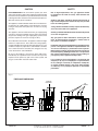
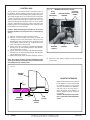
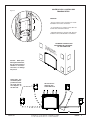
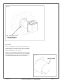
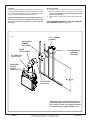
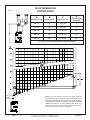
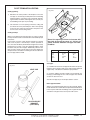
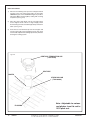
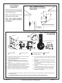
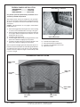
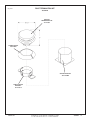
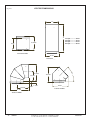
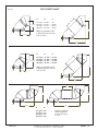
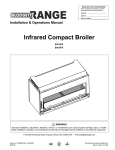
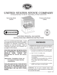
IMPORTANT:
THESE INSTRUCTIONS ARE TO
REMAIN WITH THE
HOMEOWNER
FOR YOUR SAFETY
WARNING: If the information in this
manual is not followed exactly, a fire or
explosion may result causing property
damage, personal injury or loss of life.
-- Do not store or use gasoline or other
flammable vapours and liquids in the
vicinity of this or any other appliance.
-- WHAT TO DO IF YOU SMELL GAS
• Do not try to light any appliance.
• Do not touch any electrical switch; do
not use any phone in your building.
• Immediately call your gas supplier
from a neighbour’s phone. Follow
the gas supplier’s instructions.
• If you cannot reach your gas supplier,
call the fire department.
--Installation and service must be performed
by a qualified installer, service agency or
the gas supplier.
MODEL
This appliance may be installed in an
aftermarket permanently located, manufactured home (USA only) or mobile home,
where not prohibited by local codes.
TC36 AR
SERIES B
MODULAR
DIRECT VENT FIREPLACE
This appliance is only for use with the
type of gas indicated on the rating plate.
This appliance is not convertible for use
with other gases, unless a certified kit is
used.
050505-36
INSTALLATION
AND OPERATING
INSTRUCTIONS
36ARB2
5056.428091
Contents
CAUTION .............................................................................................................. 3
SAFETY ................................................................................................................ 3
INSTALLATION REQUIREMENTS ....................................................................... 5
TOP STANDOFFS................................................................................................. 5
LOCATING THE FIREPLACE .............................................................................. 5
FRAMING AND FINISHING .................................................................................. 6
HEARTH EXTENSION .......................................................................................... 8
CONTROL BOX .................................................................................................... 8
VENTING............................................................................................................. 10
WALL TERMINATION VENTING ........................................................................ 10
ROOF TERMINATION VENTING ....................................................................... 15
VENT TERMINAL CLEARANCE ........................................................................ 17
INSULATED COLLAR SHIELD .......................................................................... 18
VENT PIPE SEALANT ........................................................................................ 18
VENT RESTRICTOR ADJUSTMENT ................................................................. 19
MANUFACTURED (MOBILE) HOME ................................................................. 19
GAS SUPPLY ...................................................................................................... 20
OPTIONAL WALL SWITCH ................................................................................ 20
WINDOW FRAME REMOVAL ............................................................................ 21
FIREBOX PANELS INSTALLATION .................................................................. 22
FIRST FIRE ......................................................................................................... 23
OPERATING ....................................................................................................... 23
LIGHTING INSTRUCTIONS - Millivolt Valve .................................................... 23
LIGHTING INSTRUCTIONS - Electronic Valve ................................................ 24
MAINTENANCE .................................................................................................. 25
APPENDIX A ....................................................................................................... 25
REPLACEMENT PARTS .............................................................................. 26
REPLACEMENT PARTS-MILLIVOLT CONTROL ASSEMBLY................... 27
REPLACEMENT PARTS - ELECTRONIC CONTROL ASSEMBLY ............ 28
ELECTRONIC VALVE WIRING DIAGRAM .................................................. 29
WALL TERMINATION KIT ........................................................................... 30
WALL SHIELD/CEILING FIRESTOP THIMBLE .......................................... 30
ROOF TERMINATION KIT ........................................................................... 31
VENT PIPE DIMENSIONS............................................................................ 32
VENT OFFSET CHART ................................................................................ 33
VARIOUS GAS SUPPLY CONNECTIONS................................................... 34
SAFETY LABEL LOCATION........................................................................ 35
2
36ARB2
050505-36
CAUTION
SAFETY
FOR YOUR SAFETY - Do not install or operate your Town
and Country fireplace without first reading and understanding
this manual. Any installation or operational deviation from the
following instructions voids the Town and Country FireplacesTM
Warranty and may prove hazardous.
This appliance and its individual shutoff valve must be disconnected from gas supply piping system during any pressure
testing of that system at test pressures in excess of 1/2 psig
(3.5 kPa).
This appliance must be isolated from the gas supply piping
system by closing its individual manual shutoff valve during
any pressure testing of the gas supply piping system at test
pressures equal to or less than 1/2 psig (3.5 kPa).
Note: When lit for the first time, the appliance will emit a slight
odour for a couple of hours. This is due to the curing of paints,
sealants and lubricants used in the manufacturing process. This
condition is temporary. Open doors and windows to ventilate
area. Smoke and fumes caused by the curing process may
cause discomfort to some individuals.
Do not use the fireplace if any part has been under water.
Immediately call a qualified service technician to inspect the
fireplace and to replace any part of the control system and
any gas control which has been under water.
Due to high temperatures, this gas appliance should
be located out of traffic and away from furniture and
draperies.
Children and adults should be alerted to the hazards of
high surface temperatures and should stay away to avoid
burns or clothing ignition.
Young children should be carefully supervised when they
are in the same room as the appliance.
Clothing or other flammable material should not be placed
on or near the appliance.
Any grill, panel or door removed for servicing the unit
must be replaced prior to operating. Failure to do so
may create a hazardous condition.
Installation and repair should be done by a qualified service
person. The appliance should be inspected before use
and at least annually by a professional service person.
More frequent cleaning may be required due to excessive
lint from carpeting, bedding material, etc. It is imperative
that control compartments, burners and circulating air
passageways of the appliance be kept clean.
It is our policy that no responsibility is assumed by the
Company or by any of its employees or representatives
for any damages caused by an inoperable, inadequate,
or unsafe condition which is the result, either directly
or indirectly, of any improper operation or installation
procedures.
Fig # 1
FIREPLACE DIMENSIONS
CENTER OF
FLUE OUTLET
050505-36
TOP
STANDOFFS
36ARB2
3
Fig. # 2
COMBUSTIBLE FRAMING AND
FINISH WALL ABOVE STANDOFFS
STEEL FRAMING
MAY USE COMBUSTIBLE FACING
MATERIAL IN THIS AREA
STANDOFFS
NON-COMBUSTIBLE
FINISH MATERIAL
SEE FIG #7
NON-COMBUSTIBLE ZONE.
DO NOT INSTALL ANY
COMBUSTIBLE MATERIAL,
ELECTRICAL WIRING OR
GAS PLUMBING IN THIS
AREA.
D
E
F
A
B
C
TOP OF LINTEL BAR
FIREPLACE FRONT
MANTEL CLEARANCE CHART
MANTEL
* CLEARANCE
REF.
A
9"
D
12"
B
6"
E
6 3/4"
C
3"
F
1 1/2"
REF.
Minimum Clearances to Combustibles:
(0 mm)
Back standoffs ..................... 0 in.
(0 mm)
Top standoffs ....................... 0 in.
(0 mm)
Bottom of appliance ............. 0 in.
(0 mm)
Adjacent sidewall ................. 4 in.
(102 mm)
Ceiling to appliance ........... 24 in.
(610 mm)
MANTEL
DEPTH
Fig. # 3
ING
IL
CE
*Mantel to appliance ..........See Figure #2
M
A
N
TE
L
Side standoffs ...................... 0 in.
**
AD
J
WA ACE
N
MA LL O T
N R
SU TEL
PP
OR
T
**Maximum
Mantel extension ..........See Figure #2
4
Mantel support ..................... 4 in.
(102 mm)
Vertical vent pipe ........... 1-3/4 in.
(45 mm)
Horizontal vent pipe
Top ........................... 1-3/4 in.
Sides ........................ 1-3/4 in.
Bottom ...................... 1-3/4 in.
(45 mm)
(45 mm)
(45 mm)
36ARB2
UNIT MAY BE RECESSED UP TO
6" WITH NON-COMBUSTIBLE
MASONRY TYPE MATERIAL
050505-36
INSTALLATION REQUIREMENTS
The Town & Country Fireplace installation and venting
must conform to the current CAN/CGA-B149 installation
code (in Canada) or the current National Fuel Gas Code,
ANSI Z223.1 (in the USA), and approved per local codes.
Only qualified (licensed or trained) personnel should
install this product.
In the state of Massachusetts, only a licensed Plumber
and Gas Fitter may install this product.
Fig. # 4
Fig. # 5
TOP
STANDOFFS
TOP STANDOFFS
The top standoffs are shipped loose inside the fireplace and
must be installed on top of the fireplace as shown in fig. #4.
Do this once the fireplace is on site and in position.
LOCATING THE FIREPLACE
In planning the installation for the fireplace, it is necessary to
determine where the unit is to be installed, location of vent
system and where gas supply piping may be plumbed. Various installations are possible, such as, into an existing wall,
a corner, a built-in wall or a wall projection (see Fig. #5). Due
to high temperatures, do not locate this fireplace in areas of
high traffic or near furniture or draperies.
The minimum clearances from the fireplace to combustible surfaces must be adhered to and are shown on Fig.
# 2 and 3.
Examples of Common Locations
SEE FIG #9 FOR
DIMENSIONS
CAUTION: When selecting a location, ensure
that there is adequate room on the right hand
or left hand side of the fireplace for the control
box.
050505-36
36ARB2
5
FRAMING AND FINISHING
Note: The fireplace must be in place and venting installed
before framing in or building an enclosure around the
unit.
The Town & Country Fireplace must be framed in as described
below or totally enclosed with non-combustible material, such
as facing brick.
Determine the total thickness of facing material to be used.
A thickness of 3/4" will allow the finishing surface to be flush
with the front of the unit. If preferred, additional masonry type
non-combustible material can be installed above and to the
sides up to 6 inches proud of the appliance. The finishing
material must not interfere with glass frame access.
A Steel Stud Framing Kit is supplied with the fireplace and
must be used unless the fireplace is totally enclosed with
non-combustible material. Assemble the framing kit as per
it's instructions. Attach the steel frame to the fireplace once
Fig. # 6
the fireplace is in its final position. Secure the steel frame to
the framing brackets on each side of the unit. Ensure that
the studs are set back far enough to allow for thickness of
finishing surface.
The sides, back and top of the fireplace can be framed in
up to the steel studs and the fireplace standoffs using conventional lumber. Consult local building codes for specific
requirements.
Due to high temperatures, concrete board is supplied with
the fireplace and must be used to sheet in the front of the
fireplace, extending 12" above and 4 1/2" to the side of the
framing edge bars. See figure #7. Standard sheetrock (drywall)
may be used beyond this.
Chase Insulation: When installing this fireplace against a
non-insulated exterior wall or chase, it is recommended that the
outer walls be insulated to same degree as other exterior walls.
Do not place fireplace directly against the insulation. Cover the
insulation and plastic vapour barrier with a solid surface, such
as drywall (sheetrock). Consult local codes. Do not insulate
or use plastic vapour barrier within the framing kit.
STEEL STUD FRAMING KIT
DIMENSIONS
(TC36.BFRKITA)
NONCOMBUSTIBLE
ZONE. DO NOT INSTALL
ANY COMBUSTIBLE
MATERIAL, ELECTRICAL
WIRING, INSULATION,
PLASTIC VAPOUR
BARRIER OR GAS
PLUMBING WITHIN THE
STEEL STUD FRAMING
ALL OTHER FRAMING
CAN BE DONE WITH
CONVENTIONAL
LUMBER
6
36ARB2
050505-36
Fig. # 7
CONCRETE BOARD
DETAIL
Fig. # 8
NON-COMBUSTIBLE RECESSED
INSTALLATION DETAIL
CONCRETE
BOARD
NON-COMBUSTIBLE
MASONRY TYPE
MATERIAL
CONCRETE
BOARD
STEEL
STUDS
6"
Concrete board (or other noncombustible material) must extend 12"
above and 4 1/2" to the sides of the
framing edges.
Fig. # 9
MINIMUM COMBUSTIBLE FRAMING DIMENSIONS
Including Sheetrock
CAUTION:
When framing
for the fireplace,
ensure adequate
space is provided
for the control box.
Do not install the
control box above
the fireplace.
WARNING: Framing dimensions will vary with location of
fireplace, which may need to be adjusted to accommodate
control box placement and vent installation. Fireplace should
be in it's final location before framing.
050505-36
36ARB2
7
CONTROL BOX
Fig. # 10
The gas control system is housed in a control box remote of
the fireplace. Flexible conduits attach the control box to the
fireplace and house all the plumbing and wiring to the burner.
This unique design allows the control box to be mounted in
a variety of positions on the right or left side of the fireplace.
The box can be framed into the front right or left face or the
right or left sidewall of the fireplace enclosure. As the control
system is attached at the factory to exit the right side of the
fireplace, please see "Control Box Relocation" section to move
the control box to exit the left side.
MANUAL MILLIVOLT VALVE
PILOT
FLAME
INDICATOR
BATTERY SPARK
IGNITER
CONTROL
DOOR AND
FRAME
Caution: When positioning the control box, do not over
bend the conduit or use excessive force, as damage may
occur.
1) Remove window frame latch tool and set aside.
2) Remove 4 screws holding control panel in place and
carefully lift off over the control knobs, being sure not to
damage wires and connections to the "Pilot Flame" indicator (millivolt control system only). Carefully disconnect
wires from indicator, and set aside.
3) Attach control box to framing at predetermined depth,
allowing room for wall finishing material. Side brackets
can be adjusted for a trim fit.
4) Attach control box to framing at predetermined depth,
allowing room for wall finishing material. Side brackets
can be adjusted for a trim fit.
5) Replace door/inner frame assembly and fasten in place.
Note: Gas supply plumbing must be completed and the
spark igniter battery or backup batteries installed before
reinstalling the front control panel.
BURNER
SWITCH
CONDUIT
GAS
VALVE
6) Reconnect "Pilot Flame" indicator wiring and reinstall
control panel.
Fig. # 11
WINDOW
FRAME
HEARTH EXTENSION
1"
MAX
1/4"
HEARTH
EXTENSION
8
36ARB2
SUBFLOOR
While a hearth extension is not required
for this fireplace, one is recommended
for aesthetic reasons. The hearth
extension should be noncombustible
and must not be any more than 1"
above the bottom of the fireplace. If
thicker, fireplace must be raised up
accordingly.
Caution: Hearth extensions thicker
than 1" will interfere with the window
frame.
WINDOW
TRACK
050505-36
CONTROL BOX LOCATION AND
FRAMING DETAIL
Fig. # 12
4 1/4"
CAUTION:
12"
- A 2 foot service access clearance is recommended in front of the control box.
- If recessed into a masonry wall, allow for
control door and frame removal.
- If flush mounted on a masonry wall, allow for
conduit to exit out the bottom of control box.
9 3/8"
POSSIBLE CONTROL BOX
LOCATIONS LEFT OR RIGHT
OF THE FIREPLACE
DO
CO N
O
O NT T I
VE R N
R OL ST
A
FI
REBO LL
PL X
AC
E
Caution: When positioning the control box,
do not over bend the
conduit or use excessive force, as damage
may occur.
Alternately, the
control may be repositioned from
the right side of
the fireplace to
the left side.
050505-36
DO NOT INSTALL
CONTROL BOX
OVER FIREPLACE
36ARB2
9
VENTING
WALL TERMINATION VENTING
Before installing venting for this unit, the installer should read
these instructions to insure that the proper vent configuration
has been selected.
Use only Town and Country Termination kits #:
TCVT.WTA - Wall Termination Kit
TCVT.RTA - Roof Termination Kit
Exterior wall opening:
Determine the exact position of the fireplace so that the vent
pipe is centred (if possible) between two building framing
members. Consult your local building codes prior to proceeding. The vent kit will accommodate up to a maximum wall
thickness of 12 inches.
Vent system components approved for use with the Town and
Country Fireplace are shown in Figure #13.
1) Having determined the position of the fireplace, cut and
frame a 14 1/2 inch opening centred at a minimum height
of 68 1/2 inches above the floor. The opening may be
round or square. Height of the opening will vary with each
installation. As the horizontal vent run increases, so does
the minimum vertical rise (see Fig. #17).
Various combinations of vertical and horizontal runs may be
used. Refer to # 17 and 18 for details. For optimum performance
and flame appearance, keep the vent length to a minimum and
limit the number of elbows. Connections between each vent
system component must be tightly joined, secured with sheet
metal screws and sealed. A horizontal run of vent should have
a 1/4" rise for every 1 ft. of run towards the termination.
CAUTION: UNDER NO CONDITION SHOULD COMBUSTIBLE MATERIAL BE CLOSER THAN 1 3/4 INCHES FROM
THE TOP AND 1 3/4 INCHES FROM THE SIDES OF A
HORIZONTAL SECTION AND 1 3/4 INCHES FROM THE
VERTICAL SECTIONS OF THE VENT PIPE.
IMPORTANT: When locating the opening, it should be
noted that vent terminal clearances must be maintained.
See "Vent Terminal Clearances" section for proper clearances.
A minimum 2 foot length of pipe is required for any wall termination. With this minimum vertical rise in combination with a
90° elbow, a maximum horizontal run of 18 inches is permitted
(see Fig. #17 and 18). For longer horizontal runs greater than
18 inches, increase vertical rise appropriately.
The rise and run must be constrained to the boundaries of the
chart shown in figure #17. The horizontal run of vent must have
a 1/4" rise for every 1 ft. of run towards the termination.
Fig. # 13
Vent System
Components
Town &
Country
12" Pipe Length ........................... TCVT.811X12
18" Pipe Length ........................... TCVT.811X18
24" Pipe Length ........................... TCVT.811X24
48" Pipe Length ........................... TCVT.811X48
18" Adjustable Pipe Length ......... TCVT.811X12ADJ
45° Elbow .................................... TCVT.811XLB45
90° Elbow .................................... TCVT.811XLB90
Wall/Offset Support ..................... TCVT.811XOS
Wall Termination Kit .................... TCVT.WTA
Roof Termination Kit .................... TCVT.RTA
Wall Shield/Ceiling Firestop......... TCVT.THIMA
Roof Flashing, Adjustable............ TCVT.811FLADJ
Roof Flashing, Flat ...................... TCVT.811FLFLT
Roof Flashing, Steep ................... TCVT.811FLSTP
or any that fits 11" pipe
10
36ARB2
050505-36
Fig. # 14
WALL THIMBLE AND VENT
MUST NOT PROTRUDE
BEYOND SIDING
Wall thimble:
Where a vent pipe passes through a combustible wall, a wall
thimble/shield must be used to retain insulation and maintain
proper clearances. The wall thimble may be cut to length for
various wall thicknesses up to 12" thick.
Measure the wall thickness including the siding. Trim the
shield to match the wall thickness. Position the wall thimble
from inside through the 14-1/2" opening. Properly adjusted,
the thimble should be flush with the outer wall surface.
Fig. # 15
TRIM TO LENGTH
050505-36
36ARB2
11
Vent pipe:
Install vent pipe through the wall thimble and attach to flue
outlet collar on top of the fireplace. Secure all joints with screws
and seal with approved "High Temp." self-adhesive aluminum
tape provided (see VENT PIPE SEALANT section).
The fireplace position may need to be adjusted to ensure
that the vent pipe does not protrude beyond the outer
wall or be recessed any more than 12 inches with the
inner pipe.
Fig. #16
Wall vent terminal:
1) Engage the 8" vent collar with the vent pipe and slide
terminal into place. Attach the terminal to the outside
wall. The vent terminal must not be recessed into the
exterior wall or siding.
2) Caulk in place to prevent any moisture entering the building.
NOTE: MINIMUM CLEARANCES TO THE VENT TERMINAL
MUST BE MAINTAINED (see Fig. #17).
14 1/2" FRAMED
OPENING
WALL SHIELD
THIMBLE
TCVT.THIMA
ELBOW
TCVT.811XLB90
HORIZONTAL
TERMINAL
TCVT.9360
24" VENT PIPE
TCVT.811X24
INSULATED
COLLAR
SHIELD
TC36.9709
12" VENT PIPE
TCVT.811X12
*
* Minimum height from the floor to center of
the opening with a maximum horizontal run
of 18" using TC Vent. The height will need to
be increased with a longer horizontal run .
12
36ARB2
050505-36
WALL
TERMINATION
VENTING CHART
Fig. # 17
D
A
B
C
Minimum rise
Pipe length
Maximum run
Pipe length
Maximum
68 1/2”
24”
18"
1'
74 1/2”
30”
76"
5'
80 1/2”
36”
11' 2 1/8"
10'
86 1/2”
42”
16'
15'
92 1/2”
48”
20’ 10 1/4”
20'
For other rise/run combinations see chart below
24" Pipe
length
minimum
NOTE: The vent must not exceed a total length of 68 feet. Any
combination of rise and run may be used but must be constrained
to the boundaries of this chart. A total of 3 90° elbows or
combination of other elbows equalling 90° can be used without
reducing horizontal run. For each additional 90° elbow, or an
equal combination of elbows, reduce horizontal vent run by 2
feet. Ensure vent pipe is properly supported.
*
050505-36
Minimum Vent Pipe Centerline Height
36ARB2
13
Fig. # 18
ROOF TERMINATION
VENTING CHART
D
A
B
C
Minimum rise
Pipe length
Maximum run
Pipe length
Maximum
68 1/2”
24”
26 5/16"
1'
74 1/2”
30”
84 3/8"
5'
80 1/2”
36”
11' 10 1/2"
10'
86 1/2”
42”
16' 8 1/2"
15'
92 1/2”
48”
21’ 6 5/8”
20'
For other rise/run combinations see chart below
24" Pipe
length
minimum
14
36ARB2
NOTE: The vent must not exceed a total length of 68 feet.
Any combination of rise and run may be used but must be constrained to the boundaries of this chart. A total of 4 90° elbows
or combination of other elbows equalling 90° can be used without
reducing horizontal run. For each additional 90° elbow, or an
equal combination of elbows, reduce horizontal vent run by 2
feet. Ensure vent pipe is properly supported.
050505-36
ROOF TERMINATION VENTING
Fig. # 20
Ceiling opening:
A
1) Determine the exact position of the fireplace so that the
vent pipe is centered (if possible) between two building
framing members. Lay out the vent system path, minimizing the number of elbows and length of vent. Consult your
local building codes prior to proceeding.
14 1/2"
2) Cut and frame a 14 1/2" opening in the floor, ceiling and
roof where the vent system will pass. Size of the opening
in the roof may need to be increased as the pitch of the
roof increases. Avoid cutting rafters.
B
Ceiling firestop:
Where a vent pipe passes through a floor or ceiling, a ceiling
firestop must be used to retain insulation and maintain proper
clearances.
From below, push the ceiling firestop through the opening
and secure in place. If the firestop is used to penetrate a
floor, the outer shield may be trimmed in length. If the firestop
penetrates into an attic, leave the shield full length to keep
insulation away from the vent pipe. Additionally, after the vent
pipe is in place, install a storm collar on top of the shield. This
will prevent loose insulation from falling into the area between
the vent pipe and the shield.
Size of the opening will have to increase with
the pitch of the roof to ensure a 1 3/4 inch air
space clearance between vent pipe and combustibles.
Roof Pitch
0/12
4/12
6/12
8/12
12/12
A
14 1/2"
16 1/2"
18"
19 3/4"
24"
B
7 1/4"
8 3/4"
10"
11"
13 3/4"
Vent pipe:
Fig. # 19
VENT PIPE
1) Install the first section of vent pipe into the collar on top of the
fireplace. Secure in place with screws and seal with approved
"High Temp." self-adhesive aluminum tape provided.
2) Continue adding vent pipe lengths up and through the
firestop(s) and through the roof. The vent pipe must extend
at least 24" above the roof.
Seal the vent pipe as per "Vent Pipe Sealant" section.
Roof support bracket:
Slip the roof support bracket down over the vent pipe. Rotate
the 90° brackets to accommodate roof pitch. Attach the brackets
to the roof joists with nails or building screws. Tighten the band
around the vent pipe and secure in place with screws.
ROOF SUPPORT
BRACKET
(TCVT.93915)
050505-36
36ARB2
15
Roof vent terminal:
1) Place the roof flashing over top of the vent pipe and nail
securely to the roof using roofing nails, top and sides
UNDER shingles, lower end OVER shingles to provide a
watershed. Make weather tight by sealing with a roofing
compound (see Fig. #21).
2) Place the storm collar down over the vent pipe until it
is level. Tighten storm collar for a snug fit. Apply a thick
horizontal ring of mastic around the pipe at top of the storm
collar (see Fig. #21).
3) Lower the roof vent terminal cap over the vent pipe and
secure in place with screws provided (see Fig. #21). Seal
screw heads and joint with caulking to prevent any moisture
entering the venting system.
Fig. # 21
VERTICAL TERMINATION CAP
(TCVT.9365)
VENT PIPE
MASTIC
STORM COLLAR
(TC42.90665)
FLASHING
16
36ARB2
Note: Adjustable for various
roof pitches, from flat roof to
12/12 pitch roof.
050505-36
VENT TERMINAL
CLEARANCE
VENT TERMINAL MINIMUM
CLEARANCES TO ADJACENT
STRUCTURES
Fig. # 22a
Minimum clearances to the vent terminal
must be maintained as shown in figure #22a
& b. Measure clearances to the nearest
edge of termination hood.
36"
(91.5 cm)
24"
(61 cm)
NOTE: Vent terminal must not be
recessed into a wall or siding.
NOTE: LOCAL CODES OR REGULATIONS MAY REQUIRE DIFFERENT
CLEARANCES.
24"
(61 cm)
48"
(122 cm)
ADJACENT
STRUCTURES
OR FENCE
VENT TERMINAL MINIMUM
CLEARANCES
Fig. # 22b
G
INSIDE
CORNER
DETAIL
V
A
H
D
E
C
V
L
V
B
F
FIXED
CLOSED
B
V
OPENABLE
V
OPENABLE
V
FIXED
CLOSED
I
G
V
B
J
A
A
V VENT TERMINAL
A AIR SUPPLY INLET
A= clearances above grade, veranda, porch, deck, or balcony
[* 12 inches (30 cm) minimum]
B= clearance to window or door that may be opened [* 12
inches (30 cm) minimum]
C= clearance to permanently closed window [minimum 12
inches (30 cm) recommended to prevent condensation on
window]
D= vertical clearance to ventilated soffit located above the terminal within a horizontal distance of 2 feet (60 cm) from the
edge of the terminal [30 inches (76 cm) minimum]
E= clearance to unventilated soffit [30 inches (76 cm) minimum]
F= clearance to outside corner [6 inches (15 cm) minimum]
G= clearance to inside corner [6 inches (15 cm) minimum]
AREA WHERE TERMINAL
IS NOT PERMITTED
M
V
K
A
G GAS METER
H= * not to be installed above a meter/regulator assembly within
3 feet (90 cm) horizontally from the center-line of the regulator
I= clearance to service regulator vent outlet [* 6 feet (1.8 m)
minimum]
J= clearance to non-mechanical air supply inlet to building or
the combustion air inlet to any other appliance [* 12 inches
(30 cm) minimum]
K= clearance to a mechanical air supply inlet [* 6 feet (1.8 m)
minimum]
L= ^ clearance above paved side-walk or a paved driveway
located on public property [* 7 feet (2.1 m) minimum]
M= clearance under veranda, porch, deck, or balcony [30
inches (76 cm) minimum**]
^ a vent shall not terminate directly above a side-walk or paved driveway which is located between two single family dwellings and
serves both dwellings*
** only permitted if veranda, porch, deck, or balcony is fully open on a minimum of 2 sides beneath the floor*
* as specified in CGA B149 Installation Codes, Note: local Codes or Regulation may require different clearances
050505-36
36ARB2
17
VENT PIPE SEALANT
Fig. #23
APPROVED
"HIGH TEMP."
SELF-ADHESIVE
ALUMINUM
TAPE
VENT PIPE
INSULATED COLLAR
SHIELD (Included) MUST
BE USED. SEE SECTION
BELOW
VENT PIPE SEALANT
All outer joints of the vent pipe must be sealed with the approved "High Temp." self-adhesive aluminum tape provided.
Wrap the tape completely around the joint and press firmly
in place.
Fig. #24
INSULATION
COVER (2 pcs.)
BEND
TABS
INSULATED COLLAR SHIELD
(Included Pt# TC36.9709)
After sealing the vent pipe an insulating blanket and cover
must be installed around the vent pipe, flush with the top of
the unit and secured by fitting tabs through slots and bending
over tabs 180° as shown in fig #24. The parts required are
included. *NOTE: bending tabs to 90° away from arc bend
18
36ARB2
050505-36
VENT RESTRICTOR ADJUSTMENT
Fig. # 26
WALL AND ROOF
TERMINATION
RESTRICTOR
POSITION
The vent restrictor is located on the underside of the firebox
top. The unit leaves the factory with the vent restrictor wide
open. The restrictor is built into the appliance for secondary
air flow adjustment. Adjustment enables tuning the airflow
for optimum flame appearance and performance for a wide
variety of vent configurations.
48'
Setting:
- determine the vent height
- determine the vent horizontal length
- from the chart determine the restrictor position
Refer to the chart in Fig. 26 for the correct position of restrictor
for the vent configuration of your installation. Restrictor positions are based upon lab tests. The ideal position may vary
slightly with installation.
Restrictor position is too closed if the flame has the following
characteristics:
- Flame is excessively tall and lifting.
- Flame lacks movement.
- Flame soots.
Restrictor position is too open if the flame has the following
characteristics:
- Flame height is low.
- Flame has excessive movement.
40'
1" OPEN NG
3/4" OPEN LP
30'
30'
2" OPEN
22'
20'
20'
To adjust the restrictor:
- Loosen the screw holding the restrictor.
- Push the restrictor back to its intended opening.
- Tighten the screw
18'
3" OPEN
12'
10'
10'
FULLY OPEN
8'
Fig. # 25
VENT RESTRICTOR
OPENING
6'
4'
2'
18"
4'
6'
8'
10'
12'
14'
16'
18'
20'
0'
0'
MANUFACTURED (MOBILE) HOME
In some jurisdictions, the Town & Country Fireplace may
be installed in Manufactured Homes after the "first sale".
Consult local codes for approval. The fireplace must be
fastened in place.
Install in accordance with the current standard Mobile Homes,
CAN/CSA Z240 MH (in CANADA), and the Manufacturer's
Home Construction and Safety Standard, Title 24 CFR,
Part 3280 or the current Standard for Fire Safety Criteria for
Manufactured Home Installations, Sites and Communities
ANSI/NFPA 501A (in the U.S.A.).
050505-36
36ARB2
19
GAS SUPPLY
Caution: The gas line should be installed by a qualified
service person in accordance with all building codes. This
section is intended as a guide for qualified technicians
installing this appliance. Consult local and/or national
building codes before proceeding.
Recommended Thermostat Wire Size
Wire Size
Max. Length
14 ga............................. 100 ft.
16 ga.............................. 60 ft.
18 ga.............................. 40 ft.
20 ga.............................. 25 ft.
22 ga.............................. 18 ft.
A gas supply line access hole is located at the bottom right
side of the Control Box. Gas valve inlet accepts a 3/8" N.P.T.
fitting. Correct gas line diameter must be used to assure
proper operation.
The gas control is equipped with a capture screw type pressure test port, therefore it is not necessary to provide an 1/8
inch N.P.T. plugged tapping pressure port for checking gas
pressure immediately upstream of the gas supply connection
to the appliance.
OPTIONAL WALL SWITCH
OR THERMOSTAT (Canada Only)
Note: Use of a wall thermostat is only permitted in
Canada.
WARNING: Do not connect 110 - 120 VAC to the gas control
valve or control wiring system of this unit.
Correct gas pressure requirement:
Min. Pressure
Natural Gas
Propane
5.0" wc
12.5" wc
13.9" wc
13.9" wc
(For purpose of input adjustment)
Max. Pressure
Manifold Pressure
Maximum
Minimum
3.8" wc
2.1" wc
11" wc
5.5" wc
Manual Millivolt Valve Only: No electrical connection is required for the gas system operation. The self-generating pilot
provides current for the remote wall switch or wall thermostat
(not provided).
The installation of a wall switch allows for manual remote
operation of fireplace, and automatic operation with a wall
thermostat. Use a switch or thermostat that is millivolt rated.
Position the wall switch or thermostat so that a minimum length
of wire is used from the switch to the fireplace. Use appropriate wire gauge for length of wire. Connect the wall switch to
the valve as shown in figure #27.
MANUAL MILLIVOLT VALVE
Fig # 27
INLET
PRESSURE
TEST POINT
OPTIONAL
WALL THERMOSTAT
Canada Only
(GASC.THERMO)
GAS VALVE
THERMOPILE
10
20
30
OPTIONAL
REMOTE CONTROL
I
OR
N
OFF
P L T
O
O
E
MANIFOLD
PRESSURE
TEST POINT
A
INDICATOR
I
PILOT FLAME
ADJUSTMENT
SCREW
O
L
H
ON
OFF
PI LOT
TP TH
* BURNER
ROCKER
SWITCH
TP
OR
TH
OPTIONAL
WALL SWITCH
* NOTE: ROCKER SWITCH MUST BE IN OFF POSITION WHEN USING OPTIONAL WALL SWITCH OR THERMOTSTAT
20
36ARB2
050505-36
WINDOW FRAME REMOVAL
Warning: Turn off the fireplace, and allow ample time for the
unit to cool before proceeding.
Caution: The ceramic glass is very fragile, and should be
handled with care.
Fig # 29
UPPER FIREBOX SHIELD
The window frame is held in place by two spring-loaded
latches and are operated by a removable handle. The handle
is located in the Control Box.
1) Insert the latch handle onto the catch located 6” down
from the top corners. Rotate up to disengage each of the
two catches.
2) Tilt the top of the window frame out to clear the top edge
of the unit. Grasp the sides of the frame and lift up and
out to disengage from its bottom track.
3) Place the window frame in a safe place to avoid damage.
SIDE PANEL RETAINER
Reassemble in reverse order.
Fig # 30
Fig # 28
050505-36
36ARB2
21
FIREBOX PANELS INSTALLATION
Fig. #32
ADJUSTABLE "V" BRACKET
(HERRINGBONE .................. TCPN.7566)
(TUSCAN ................................ TCPN.748)
(HERITAGE RED................ TCPN.75704)
For porcelin panel kit (TCPN.75702) installation see instructions provided with panel kit.
The Firebox Panels have to be installed for safe operation.
Do not use the fireplace without panels. Unpack and inspect
all panels. The panels need to be installed before the logs
are in place.
Caution: The Brick Panels are very fragile, and should be
handled with care.
1) Remove the log grate by removing the two screws retaining
it. Screws are located behind the front legs of the grate.
2) Remove the Side Panel Retainers located on the underside
of the upper firebox heatshield. The retainers are each
held in place by one screw.
3) Install the Lower Rear Panel.
4) Install the Right Side Panel by inserting the bottom of the
panel in first and then angling it up into position.
5) Install the Left Side Panel by inserting the bottom of the
panel in first and then angling it up into position.
The rear panel is held tight against the side panels by two "V"
brackets located on the firebox rear wall. Although the brackets
are adjusted at the factory for the best fit, some adjustment
may be necessary. Adjust the angle of the bracket by hand
to ensure a snug fit.
Fig. # 31
REAR LOWER PANEL
6)
7)
8)
9)
Install the Rear Upper Panel.
Re-install the Side Panel Retainers.
Install the Left and Right Front Panels.
Replace the Grate.
HERRINGBONE PANEL SET SHOWN
REAR UPPER
PANEL
RIGHT SIDE
PANEL
LEFT SIDE
PANEL
REAR LOWER
PANEL
LEFT FRONT
PANEL
22
36ARB2
RIGHT FRONT
PANEL
050505-36
LIGHTING INSTRUCTIONS - Millivolt Valve
FOR YOUR SAFETY READ BEFORE LIGHTING
WARNING: If you do not follow these instructions
exactly, a fire or explosion may result causing
property damage, personal injury or loss of life.
A. This appliance is equipped with an ignition device which automatically lights the pilot. Do not try to light the pilot by hand.
B. BEFORE LIGHTING smell all around the appliance area for gas.
Be sure to smell next to the floor because some gas is heavier
than air and will settle on the floor.
WHAT TO DO IF YOU SMELL GAS:
- Do not try to light any appliance.
- Do not touch any electric switch; do not use any phone in your
building.
- Immediately call your gas supplier from a neighbour's phone.
Follow the gas supplier's instructions.
- If you cannot reach your gas supplier, call the fire department.
C. Use only your hand to push in or turn the gas control knob.
Never use tools. If the knob will not push in or turn by hand,
don't try to repair it, call a qualified service technician. Force or
attempted repair may result in a fire or explosion.
D. Do not use this appliance if any part has been under water.
Immediately call a qualified service technician to inspect the
appliance & to replace any part of the control system & any gas
control which has been under water.
LIGHTING INSTRUCTIONS
1.
2.
3.
4.
STOP! Read the safety information above on this label.
Set wall thermostat to lowest setting, if applicable.
Turn off all electric power to the appliance, if applicable.
This appliance is equipped with an ignition device which
automatically lights the pilot. Do not try to light the pilot by
hand.
5. Partially depress and turn gas control
knob clockwise
past "Pilot" to "Off"
position.
Note: Knob cannot be turned from "Pilot" to
"Off" unless knob is pushed in slightly.
Do not force.
6
Allow sufficient length of time (minimum 5 minutes) for any
gas in the combustion chamber to escape. If you still smell
gas, STOP! Follow "B" in the safety information above on
this label. If you don't smell gas, go to the next step.
7. Turn gas control knob back to "Pilot" position.
8. Depress gas control knob fully and hold to ignite pilot. Once
the pilot ignites, continue depressing knob for approximately 5 seconds, or until pilot flame indicator is in the RED
zone. If pilot does not stay lit, repeat steps 5 through 8,
allowing a longer period before releasing gas control dial.
- If gas control knob does not pop up when released, stop
and immediately call your service technician or gas supplier.
- If the pilot will not stay lit after several tries, turn the gas
control knob to "Off" and call your service technician or gas
supplier.
to "On" posi9. Turn gas control knob counter-clockwise
tion.
10. Turn HI-LO burner control knob to desired setting.
11. Turn on the burner switch and close control door.
12. Turn on all electric power to the appliance, if applicable.
13. Set thermostat to desired setting, if applicable.
Note: Sufficient time must be allowed for air to escape from
lines if the unit is being lit for the first time.
TO TURN OFF GAS TO APPLIANCE
1. Set wall thermostat to lowest setting, if applicable.
2. Turn off all electric power to the appliance if service is to be
performed.
FIRST FIRE
When lit for the first time, the fireplace will emit a slight odour
for a couple of hours. This is due to the curing of paints, sealants and lubricants used in the manufacturing process. This
condition is temporary. Open doors and windows to ventilate
area. Smoke and fumes caused by the curing process may
cause discomfort to some individuals.
It is normal for fireplaces fabricated of steel to give off some
expansion and/or contraction noises during the start up or
cool down cycle. Similar noises are found with your furnace
heat exchanger or cook stove oven.
050505-36
3. Push in gas control knob slightly and turn clockwise
"Off". Do not force.
to
OPERATING
The Town and Country Fireplace comes equipped with either
a manual (millivolt) combination gas valve or an electronic
gas valve. An optional wall switch or thermostat (Canada
only) may be installed to operate the burner automatically on
both types of valve.
Manual Valve: Once a pilot light has been established,
and the gas valve knob turned to the "ON" position (Manual
Valve) or simply switched on with the "Burner" switch, the unit
may be operated in one of two ways; manually adjusting the
flame and/or turning the unit on and off automatically with a
wall thermostat.
36ARB2
23
1) HI-LO Flame Adjustment:
The HI-LO burner control knob can be rotated in both directions, providing infinite control of gas flow rate to the burner
and therefore greater comfort control. The HI setting provides a
maximum gas input, and rotating the knob clockwise toward the
LO setting will reduce the gas input to a minimum setting.
2) Wall Thermostat - Canada Only (Optional part # GASC.THERMO):
Set the wall thermostat to a comfortable temperature. Turn
the HI-LO burner control knob to a desired setting. As heat is
required, the fireplace will turn on or off automatically.
Electronic Valve: Push the "Burner" switch to the "Off" position. Turn off all electric power to the appliance and remove
backup batteries if service is to be performed or for extended
shutdown.
Fig. # 33
HI-LO Control Knob
Extend Shutdown:
Manual Valve: To shutdown the appliance including the pilot,
partially depress and turn gas control knob clockwise past
“PILOT” to “OFF” position. DO NOT FORCE.
NOTE: The SIT control has an interlock device which does
not allow the pilot to be lit when the appliance is at operating
temperature. Let the appliance cool down (approx. 60 sec.)
before attempting to relight the pilot. DO NOT use force to
rotate the control knob.
BURNER CONTROL
LIGHTING INSTRUCTIONS - Electronic Valve
FOR YOUR SAFETY READ BEFORE LIGHTING
WARNING: If you do not follow these instructions
exactly, a fire or explosion may result causing
property damage, personal injury or loss of life.
A. This appliance is equipped with an ignition device which automatically lights the pilot. Do not try to light the pilot by hand.
B. BEFORE LIGHTING smell all around the appliance area for gas.
Be sure to smell next to the floor because some gas is heavier
than air and will settle on the floor.
WHAT TO DO IF YOU SMELL GAS:
- Do not try to light any appliance.
- Do not touch any electric switch; do not use any phone in your
building.
- Immediately call your gas supplier from a neighbour's phone.
Follow the gas supplier's instructions.
- If you cannot reach your gas supplier, call the fire department.
C. Use only your hand to push in or turn the gas control knob.
Never use tools. If the knob will not push in or turn by hand,
don't try to repair it, call a qualified service technician. Force or
attempted repair may result in a fire or explosion.
D. Do not use this appliance if any part has been under water.
Immediately call a qualified service technician to inspect the
appliance & to replace any part of the control system & any gas
control which has been under water.
LIGHTING INSTRUCTIONS
1. STOP! Read the safety information above on this label.
2. Set wall thermostat to lowest setting, if applicable.
3. This appliance is equipped with an ignition device which
automatically lights the pilot. Do not try to light the pilot by
hand.
4. Push the "Burner" switch to the "Off" position.
5. Allow sufficient length of time (minimum 5 minutes) for any
gas in the combustion chamber to escape. If you still smell
gas, STOP! Follow "B" in the safety information above on
this label. If you don't smell gas, go to the next step.
6. Push the "Burner" switch back to the "On" position.
- If the burner does not light, repeat steps 4 through 6.
- If the burner will not light or stay lit after several tries,
turn the "Burner" switch to the "Off" position and call your
service technician or gas supplier.
Note: Sufficient time must be allowed for air to escape from
lines if the unit is being lit for the first time.
7. Turn HI-LO burner control knob to desired setting and close
control door.
8. Set thermostat to desired setting, if applicable.
TO TURN OFF GAS TO APPLIANCE
1. Set wall thermostat to lowest setting, if applicable.
2. Push the "burner" switch to the "Off" position.
3. Turn off all electric power to the appliance and remove
backup batteries if service is to be performed or for extended
shutdown.
Due to high surface temperatures, keep children, clothing and furniture away. Keep burner and control compartment clean. See
installation and operating instructions accompanying the appliance.
A cause de la temperature elevee des parios, tenir eloignes les enfants, les vetements et les meubles. Maintenir propres le
bruleur et le compartiment de commande. Voir les instructions relatives a l'installation et au fonctionnement qui accompagnent
l'appareil.
24
36ARB2
050505-36
APPENDIX A
Annual Inspection:
MAINTENANCE
Caution: Turn off gas and electrical power supply (if applicable) and allow ample time for unit to cool before servicing
appliance. It is recommended that the fireplace and its venting should be inspected at least once a year by a qualified
service person.
a) Remove glass panel and log set. Inspect logs and burner
assembly for soot buildup. If excessive buildup of soot is
present, have a qualified service person inspect and adjust unit
for proper combustion. Clean logs and burner with a brush or
vacuum cleaner, paying close attention to burner ports.
Glass Panel:
Warning: Do not operate fireplace with glass panel removed,
cracked or broken. Replacement of the glass panel should be
done by a licensed or qualified service person.
Do not strike or otherwise impact the glass in anyway that may
cause it to break. If the glass becomes cracked or broken,
it must be replaced before using the fireplace. Replacement
glass can be obtained from your nearest Town and Country
FireplacesTM dealer. The size required is 36" x 30" x 5mm.
Use ceramic glass only. Do not substitute with any other
type.
To remove broken glass, remove window frame as noted in
"Window Frame Removal" section.
Unclip the Glass Retainer Clips located at the top of the Window Frame. Pull the top edge of the glass out of the frame
first, then lift it up and out of the bottom edge.
Install the new piece of glass with the gasket into the frame
so that the thicker bead of gasket faces the fireplace.
b) Check the pilot system for proper flame size and operation. Clean pilot free of soot, dust or any other deposits. (See
Fig. #35 and 36)
Fig. # 34
ELECTRONIC PILOT
c) Check that the vent pipe and vent terminal are open and
free from blockage or debris. If the venting is disassembled
for cleaning, it must be properly assembled and re-sealed.
Refer to VENTING section for proper procedure.
d) Check glass panel gasket, replace if necessary. It is important
that the glass seal be maintained in good condition.
e) Check and replace batteries as needed.
Note: The appliance area must be kept clear and free from
combustible materials, gasoline and other flammable vapours
and liquids.
Periodically:
a) Viewing glass may be cleaned as necessary with fireplace
glass cleaner.
b) Exterior finish may be cleaned with mild soap and water.
PILOT FLAME
CAUTION:
Do not use abrasive cleaners on glass or any other
part of the fireplace.
FLAME SENSOR
ELECTRODE
Do not clean glass when hot.
MILLIVOLT PILOT
Fig. # 35
THERMOPILE
THERMOCOUPLE
PILOT FLAME
ELECTRODE
050505-36
36ARB2
25
REPLACEMENT PARTS
(WHEN ORDERING, INCLUDE PART NUMBER WITH DESCRIPTION)
ITEM
DESCRIPTION
PART NO.
1............ GLASS FRAME........................... TC36.9520WLD
2............ REPLACEMENT GLASS (c/w gasket) GLAS.2088
.............. GLASS RETAINER, TOP....................... 9050.001
.............. GLASS GASKET KIT ................................. 2087.1
.............. FRAME & GLASS ASSEM.................. TC36.9520
4............ CONTROL DOOR ASSEMBLY .......... TC42.9074
6............ SPRING LATCH ASSEMBLY ............. TC42.9024
5............ REMOVABLE LATCH HANDLE ......... TC42.9028
7............ PANEL, RIGHT SIDE, HERNGBN ....... 5098.7565
.............. PANEL, RIGHT SIDE, TUSCAN .......... 5098.7474
.............. PANEL, RT SIDE, HERITAGE RED . 5098.7571.3
8............ PANEL, UP. BACK, HERRINGBONE .. 5098.7563
.............. PANEL, UP. BACK, TUSCAN .............. 5098.7472
.............. PANEL, UP BACK, HERITAGE RED 5098.7571.1
9............ PANEL, LEFT SIDE, HERNGBN ......... 5098.7564
.............. PANEL, LEFT SIDE, TUSCAN ............ 5098.7473
.............. PANEL, LT SIDE, HERITAGE RED .. 5098.7571.2
10.......... PANEL, LEFT BASE, BRICK ................. 5098.755
.............. PANEL, LEFT BASE, TUSCAN ........... 5098.7466
.............. PANEL, LT BASE, HERITAGE RED. 5098.7571.5
11.......... PANEL, RIGHT BASE, BRICK............... 5098.756
.............. PANEL, RIGHT BASE, TUSCAN ......... 5098.7467
.............. PANEL, RT BASE, HERITAGE RED 5098.7571.6
ITEM DESCRIPTION
PART NO.
12.......... PANEL, LOWER BACK, HERNGBN ... 5098.7562
.............. PANEL, LOWER BACK, TUSCAN....... 5098.7471
.............. PANEL, LW BK, HERITAGE RED .... 5098.7571.4
.............. PANEL SET, HERRINGBONE........... TCPN.7566
.............. PANEL SET, TUSCAN......................... TCPN.748
.............. PANEL SET, HERITAGE RED ........ TCPN.75704
13.......... FLUE DAMPER TAB.................................. 9104.7
14.......... FLUE DAMPER...................................... 9004.501
.............. SHIELD INSULATION (not shown) ........... 9504.5
.............. SHIELD INSULATION (not shown) ........... 9504.7
.............. FIREBOX SHIELD ASSEMBLY .......... TC36.9504
15.......... FIREBOX HEAT SHIELD ............ TC36.9504WLD
16.......... BRICK PANEL RETAINER ........................ 9508.6
17.......... ANDIRON SUPPORT BRACKET ......TCDO.9087
18.......... REPLACEMENT ANDIRON............... 5035.90881
19.......... PILOT BRACKET ..................................... 9085.51
20.......... PILOT ASSEMBLY ................................ 5009.158
21.......... INSULATED COLLAR SHIELD........... TC36.9709
All parts may be ordered from your nearest Town and Country
FireplacesTM dealer. Contact Town and Country FireplacesTM
for the location of the dealer nearest you.
Fig. # 36
21
8
9
7
12
10
6
13
11
5
14
18
17
15
4
16
19
20
1
3
2
26
36ARB2
050505-36
REPLACEMENT PARTS-MILLIVOLT CONTROL ASSEMBLY
(WHEN ORDERING, INCLUDE PART NUMBER WITH DESCRIPTION)
ITEM ..... DESCRIPTION......................................PART NO.
1............ KNOB, EXT, ON/OFF 1-1/2 .................... 5007.315
2............ KNOB, EXT, HI/LO 1-1/2 ........................ 5007.316
3............ SPARKER, BOX ..................................... 5016.902
4............ FITTING, DISPL.CONN.BLK974.071 ..... 5019.006
5............ CONN, DISPLAY TAB .......................... 5019.0061
6............ FITTING, 1/2 X 3/8 90-2021.................... 5019.009
7............ FITTING, STREET ELBOW, 3/8 ............... 5019.01
8............ PIPE, STAINLESS T8 ................................. 5023.2
9............ CONTROL BOX ........................................ 9070.01
10.......... VALVE MOUNTING BRACKET, LEFT .......... 9072
11.......... VALVE MOUNTING BRACKET, RIGHT ..... 9072.5
12.......... CONTROL BOX BRACKET ........................... 9075
13.......... BURNER SWITCH WIRE ASSEM. ... OXFD.50625
14.......... VALVE ASSEM. NG (c/w sp. cable) .... TC42.5007
15.......... SPARKER, CABLE ................................. 5016.901
16.......... MINIMUM INPUT STOP ......................... 9076.001
17.......... PILOT FLAME DISPLAY ASSEM. . TC42.5007163
18.......... CONDUIT 1/2IN ASSEMBLY ......... TC42.5033501
19.......... CONDUIT 1 1/4IN ASSEMBLY ...... TC42.5033502
2
Fig. # 37
ITEM ......DESCRIPTION ....................................PART NO.
20.......... LOWER CONTROL PANEL ASSEM. .. TC42.9071
21.......... SWITCH, BURNER ........................................ 5071
22.......... UPPER CONTROL PANEL ASSEM. . TC42.90715
PILOT ASSEMBLY NG ...................................... TC42.5009
.............. WIRE, ELECTRODE, 75" ......................... 5002.66
.............. TUBE, PILOT.1875 OD x.035wx50' ........ 5004.001
.............. PILOT, BRACKET ................................... 5009.161
.............. PILOT, HOOD, 3 FLAME ........................ 5009.162
.............. PILOT ORIFICE-NG-CON#62 .................. 5009.17
.............. PILOT ORIFICE-LP-CON#35 ................. 5009.169
.............. ELECTRODE .......................................... 5009.501
.............. THERMOPILE, 75" ................................. 5010.301
.............. FITTING, OLIVE 3/16.............................. 5019.001
.............. FITTING, NUT, 3/16 ................................ 5019.002
.............. FITTING, LOXIT 3/16 .............................. 5019.003
.............. FITTING, NUT, ELECTRODE ................. 5019.004
.............. THERMOCOUPLE ASSEMBLY .... TC42.5010302
1
3
9
15
22
16
20
14
11
10
7
7
12
12
6
13
4
5
8
050505-36
19
18
17
21
36ARB2
27
REPLACEMENT PARTS - ELECTRONIC CONTROL ASSEMBLY
ITEM ..... DESCRIPTION......................................PART NO.
1............ ELECTRONIC, VALVE, NG ...................... 5030.01
2............ ELECTRONIC, IGNITION MODULE......... 5030.02
3............ ELECTRONIC, BATTERY HOLDER ........ 5030.03
4............ ELECTRONIC, AC ADAPTOR.................. 5030.04
5............ ELECTRONIC, WIRE HARNESS ..........5030.05.A
6............ ELECTRONIC, KNOB EXTENSION ......... 5030.06
7............ VALVE BRACKET BOTTOM ......................... 9078
8............ VALVE BRACKET TOP .............................. 9078.5
9............ TRANSFORMER BRACKET ...................... 9079.5
ITEM ......DESCRIPTION ....................................PART NO.
10.......... LOWER CNTRL PNL ASSY ELEC .... TC42.90712
11.......... RECEPTACLE BOX ASSEMBLY ........ TC42.9079
12.......... BATTERY RELAY BOX .......................... 5030.021
13.......... RELAY BRACKET .................................. 9079.601
14.......... SWITCH, BURNER ........................................ 5071
ELECTRONIC, PILOT ASSEMBLY, NG ................. 5030.07
All other replacement parts are the same as the parts on the
Millivolt Control Assembly. See figure #38.
Fig. # 38
2
10
5
3
6
1
11
14
4
12
9
13
8
7
28
36ARB2
050505-36
ELECTRONIC VALVE WIRING DIAGRAM
Fig. # 39
2
Pilot
Assembly
Black (S)
[through Gas
line conduit]
S
I
Note: Wire Tags
are bracketed
Ignition
Module
Electrode
3
Flame
Sensor
Black (I)
[through
independent
conduit]
Battery
Holder
Black
Pilot
Gas Line
14 Burner
IN
Switch
TH
TP
OUT
TH
PILOT
LO
HI
TP
VENT
Red
1
Gas Valve
12 Battery
Relay
5
Black
AC Adaptor
CAUTION:
4
Wire
Harness
Module
Plug
Black
Black
(TP)
Orange
Orange x2
(THTP)
Brown
(SWI)
TH
TP
TH
Red
(+)
Black
TP
Green x2
(TH)
Yellow
Green
Black
Blue
Relay
Plug
050505-36
36ARB2
29
Fig. # 40
WALL TERMINATION KIT
TCVT.WTA
WALL
TERMINAL
TCVT.9360
WALLSHIELD/CEILING
FIRESTOP THIMBLE
TCVT.THIMA
Fig. # 41
WALL SHIELD/CEILING FIRESTOP THIMBLE
TCVT.THIMA
30
36ARB2
050505-36
Fig. # 42
ROOF TERMINATION KIT
TC36.RTA
VERTICAL
TERMINATION CAP
TCVT.9365
STORM COLLAR
TC42.90665
CEILING FIRESTOP
TCVT.THIMA
ROOF SUPPORT
BRACKET
TCVT.93915
050505-36
36ARB2
31
Fig. # 43
VENT PIPE DIMENSIONS
11"
*
10 15/16"
9 1/2"
12" Pipe ............. 10 1/4"
18" Pipe ............. 16 1/4"
24" Pipe ............. 22 1/4"
48" Pipe ............. 46 1/4"
TCVT.811X12ADJ
11 1/8"
TCVT.811X _ _
45°
13 13/16"
12 9/16"
8 5/16"
10 5/16"
15 7/8"
7/16"
1 5/16"
13 1/8"
TCVT.811XLB45
TCVT.811XLB90
32
36ARB2
050505-36
Fig. # 44
VENT OFFSET CHART
A
10 7/8"
B
C
A
12" Pipe......18 5/8"........18"
18" Pipe......22 7/8"........22 3/8"
24" Pipe......27 1/8"........26 1/2"
48" Pipe......44 1/16"......43 1/2"
C
Adding an adjustable section
to pipe will increase offset by
2 1/8" to 6 3/4"
1 1/4”
11 3/8"
1 1/4”
B
A
16 1/16”
1 1/4”
B
C
12" Pipe......13 7/16"......23 1/4"
18" Pipe......17 9/16"......27 5/8"
24" Pipe......21 7/8"........31 3/4"
48" Pipe......38 3/4"........44 7/8"
A
C
Adding an adjustable section
to pipe will increase offset by
2 1/8" to 6 3/4"
6 1/8"
1 1/4”
B
A
20”
20"
1 1/4”
1 1/4”
18 5/8"
A
12" Pipe......29"
18" Pipe......35"
24" Pipe......41"
48" Pipe......48"
050505-36
B
B
Adding an adjustable
section to pipe will
increase offset by 3"
to 9 1/2"
36ARB2
33
VARIOUS GAS SUPPLY CONNECTIONS
Note: Consult local codes before proceeding.
Fig. # 47
GASTITETM FLEX LINE WITH
REDUCING COUPLING
Fig. # 45
FLEXIBLE CONNECTOR
WITH SHUTOFF VALVE
Fig. # 48
COPPER LINE WITH
FLARE FITTING
Fig. # 46
BLACK IRON
PIPE WITH UNION
* USA ONLY
Copper piping may only be used in compliance with local
codes or, in the absence of local codes, with the following
National Fuel Codes:
•
NFPA54 - Section 2.6.2d
•
NFPA54 - 2002 - Section 5.6.3.2
•
ANSI Z223.1 - 2002 - Section 5.6.3.2
34
36ARB2
050505-36
VENTED GAS FIREPLACE - NOT FOR USE WITH SOLID FUEL
FOYER AU GAZ À ÉVACUATION - NE PAS UTILISER AVEC
DU COMBUSTIBLE SOLIDE
ANSI Z21.50b-2002 / CSA 2.22b-2002 Vented Gas Fireplaces
CAN/CGA 2.17-M91 Gas-Fired Appliance For Use At High Altitudes.
Certified for / Certifié pour Canada and U.S.A.
TC36
TC36AR
MODEL/
MODELE:
SERIES/
SERIE:
B
MADE IN CANADA
FABRIQUE AU CANADA
WH-
This Appliance is Equipped For Use With /
Cet Appareil est Équipé Pour Utilise Avec :
NATURAL GAS
GAZ NATUREL
LP-GAS
LP GAZ
FOR USE WITH/
EN CASE D’EMPLOI AVEC:
NATURAL GAS/
LP GAS/
DU GAZ NATUREL DU GAZ LP
Minimum supply pressure / Pression minimum d’alimentation:
5.0 in/wc / 5.0 po/c.e.
(1.25 kPa)
13.9 in/wc / 13.9 po/c.e.
(3.45 kPa)
3.8 in/wc / 3.8 po/c.e.
(.95 kPa)
(For the purpose of input adjustment / dans le but de régler l’alimenation)
Maximum supply pressure / Pression maximum d’alimentation:
Manifold pressure / Pression de la tuyauterie:
Maximum
Orifice Size / Diametre de l’injectuer:
# 30
Input BTU/hr (kW) / Entree BTU/h (kW):
Max.: 47,000 (13.8)
Min.: 35,000 (10.3)
(3.26 mm)
12.5 in/wc / 12.5 po/c.e.
(3.11 kPa)
13.9 in/wc / 13.9 po/c.e.
(3.45 kPa)
11.0 in/wc / 11.0 po/c.e.
(2.74 kPa)
# 45
(2.08 mm)
Max.: 47,000 (13.8)
Min.: 35,000 (10.3)
Optional components: Remote Heat Kit (TC36.RHKA), Propane Conversion Kit (TC36.LPKTB) / Éléments facultatifs: Kit à Distance de la Chaleur (TC36.RHKA),
Trousse de conversion (TC36.LPKTB); Blower electrical rating: 115v, 60hz, 0.5 A / Normes electriques du ventilateur: 115v, 60hz, 0.5 A
This appliance equipped for altitudes 0 - 4500 ft. (0 - 1372 m) / Cet unité est conçu pour des altitudes variant entre 0 - 4500 pieds (0 - 1372 m). In Canada, also
certified for installation in a bedroom or a bedsitting room / Aussi certifié pour installation dans une chambre à coucher ou une salle de séjour. This appliance
must be installed in accordance with local codes, if any; if none, follow the current CAN/CGA-B149 (Canada), or ANSI Z223.1 (USA) Installation Codes. Installer
l’appareil selon les codes ou règlements locaux, ou, en l’absence de tels règlements, selon les codes d’installation CAN/CGA-B149 (Canada), or ANSI Z223.1
(USA) en vigeur.
MANUFACTURED (MOBILE) HOME: This appliance is only for use with the type of gas indicated on the rating plate and may be installed in an aftermarket,
permanently located, manufactured (mobile) home where not prohibited by local codes. See owners manual for details.
FABRIQUEZ (MOBILE) MAISON: Cet appareil doit être utilisé uniquement avec le type de gaz indiqué sur la plaque signalétique et peut être installé dans une
maison préfabriquée (mobile) installée à demeure si les règlements locaux le permettent. Voir la notice du propriétaire pour plus de détails. Cet appareil ne peut
être converti à d'autres gaz sauf si une trousse de conversion certifiée est utilisée.
Install in accordance with the current standard Mobile Homes,CAN/CSA Z240 MH (in CANADA), and the Manufacturer's Home Construction and Safety
Standard, Title 24 CFR, Part 3280, or the current Standard for Fire Safety Criteria for Manufactured Home Installations, Sites, and Communities ANSI/NFPA
501A, (in the U.S.A.). Cet appareil diot être installé conformemént aux exigences de la norme CAN/CSA Z240 MH en vigueur de l'ACNOR, Installations de gaz
dans les Constructions Mobiles.
FOR USE WITH GLASS DOORS CERTIFIED WITH THE APPLIANCE ONLY / POUR UTILISATION UNIQUEMENT AVEC LES PORTES IN VERRE CERTIFIÉES
AVEC L'APPAREIL
MINIMUM CLEARANCES TO COMBUSTIBLES / CLAIRANCES MINIMALES AVEC LES COMBUSTIBLE
Left and Right side are determined when facing the front of the appliance. / Les côtés droit et gauche se déterminent
en se mettant devant l’appareil et en lui faisant face.
Top, Back and Side Standoffs / Sommet, Arrière et Côté Butée
Sidewall to Appliance / Du mur latéral a l’appareil
Ceiling to Appliance / Plafond a l’appareil
Mantel to Appliance / Du manteau al'appareil
Maximum Mantel Extension / Allongement maximum du manteau
*See Installation Manual for more detail / Voyez des Directive
de l’Installation pour plus détaux.
Mantel Supports / Supports du manteau
Vent Pipe / Déchargez le Tuyau
0 in./ 0 po.
4 in./ 4 po.
24 in./ 24 po.
*9 in./ 9 po.
*12 in./ 12 po.
(0 mm)
(102 mm)
(610 mm)
(229 mm)
(305 mm)
4 in./ 4 po.
1.75 in./ 1.75 po.
(102 mm)
(45 mm)
Pacific Energy
Fireplace Products Ltd.
Duncan, British Columbia,
Canada
WARNING: Improper installation, adjustment, alteration, service or maintenance can cause injury or property damage. Refer to the owner’s information manual
provided with this appliance. For assistance or additional information, consult a qualified installer, service agency or the gas supplier.
AVERTISSEMENT: Une installation, un réglage, une modification, une réparation ou un entretien mal effectué peut causer des dommages matériels ou des
blessures. Voir la notice de l’utilisateur qui accompgne l’appareil. Pour de l’aide ou des renseignements supplémentaires, consultez un installateur, un
technicien agréé ou le fournisseur de gaz.
270904
5050.7205.B
1-TC36-B
SAFETY
LABEL
SAFETY LABEL LOCATION
NOTE: On appliances equipped with Electronic
Ignition, the Safety Label is located behind the
lower control panel.
CONTROL
BOX
050505-36
LOWER
CONTROL
PANEL
36ARB2
35
2975 Allenby Rd., Duncan, BC V9L 6V8
Phone: 1-888-223-0088
Web site: www.townandcountryfireplaces.net
Printed in Canada