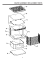
1
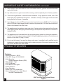
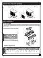
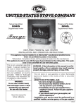
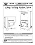
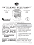
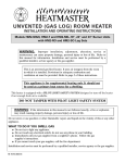
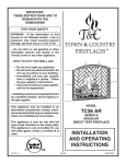
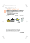
UNITED STATES
STOVE COMPANY
227 INDUSTRIAL PARK ROAD • P.O. BOX 151 • SOUTH PITTSBURG, TN. 37380 • (423)-837-2100
Natural Gas Model
C9947N
Propane (LPG) Gas Model
C9947L
Owner's Operation and Installation Manual
This appliance may be installed in an aftermarket* manufactured (mobile) home,
where not prohibited by state or local codes.
*Aftermarket: Completion of sale, not for purpose of resale, from the manufacturer
This appliance is only for use with the type gas indicated on the rating plate. This appliance is not convertible for use with other gases.
This is an unvented gas-fired
heater. It uses air (oxygen) from
the room in which it is installed.
Provisions for adequate combustion and ventilation air must be
provided. Refer to "Adequate
Combustion And Ventilation Air"
on page(s) 6 of this manual.
WARNING:
Do not use a blower insert,
heat exchanger insert or other
accessories not approved
for use with this heater.
Save this manual for
future reference.
WARNING: If the information in this manual is not
followed exactly, a fire or explosion may result
causing property damage, personal injury, or loss of
life.
~Do not store or use gasoline or other flammable
vapors and liquids in the vicinity of this or any other
appliance.
~WHAT TO DO IF YOU SMELL GAS
• Do not try to light any appliance.
• Do not touch any electrical switch; do not
use any phone in your building.
• Immediately call your gas supplier from a
neighbor's phone. Follow the gas supplier's
instructions.
• If you cannot reach your gas supplier, call
the fire department.
~Installation and service must be performed by a
qualified installer, service agency, or the gas supplier.
851371B 6/00
TABLE OF CONTENTS
SECTION
PAGE
IMPORTANT SAFETY INFORMATION.......................................................3-4
PRODUCT FEATURES..................................................................................4
9947 SPECIFICATIONS.................................................................................5
CONTENTS....................................................................................................5
ITEMS REQUIRED FOR INSTALLATION......................................................6
INSTALLATION...............................................................................................7
MANTEL CLEARANCES................................................................................8
GAS CONNECTION..................................................................................9-10
GAS PRESSURE CHECK.............................................................................10
FRONT SCREEN REMOVAL.......................................................................11
LOG ASSEMBLY...........................................................................................11
OPERATING INSTRUCTIONS................................................................12-14
CLEANING / SERVICING.......................................................................14-15
FLAME APPEARANCE................................................................................15
PARTS LIST FOR HEATER ASSEMBLY.................................................16-17
PARTS LIST FOR BURNER AND LOG ASSEMBLY...............................18-19
TROUBLE SHOOTING...........................................................................20-21
OPTIONAL EQUIPMENT..............................................................................22
WIRING DIAGRAMS...............................................................................23-25
NOTES..........................................................................................................26
LIMITED WARRANTY POLICY....................................................................27
NOTICE
Installation and repair must be done by a qualified service person. The appliance should be inspected before use and at least annually by a professional service person. More frequent cleaning
may be required due to excessive lint from carpeting, bedding material, etc. It is imperative that
control compartments, burners and circulating air passageways of the appliance be kept clean.
2
IMPORTANT SAFETY INFORMATION
INSTALLER: Please leave these instructions with the owner.
OWNER: Please retain these instructions for future reference.
IMPORTANT: Read these instructions carefully before installing or trying to operate this heater.
WARNING: Any change to this heater or its controls can be dangerous. Improper installation or
use of the heater can cause serious injury or death from fire, burns, explosion or carbon monoxide
poisoning.
1.
CARBON MONOXIDE POISONING: Early signs of carbon monoxide poisoning are similar to
the flu with headaches, dizziness and/or nausea. If you have these signs, obtain fresh air
immediately. Have the heater serviced as it may not be operating properly.
2.
The installation must conform with local codes or, in the absence of local codes, with the National
Fuel Gas Code, ANSI Z223.1.
2.
This heater shall not be installed in a bedroom or bathroom.
4.
WARNING: Improper installation, adjustment, alteration, service or maintenance can cause
injury or property damage. Refer to this owner's manual. Installation and service must be
performed by a qualified installer, service agency or the gas supplier.
5.
To prevent malfunction and/or sooting, a vent-free gas heater should be cleaned at least
annually by a professional service person. More frequent cleaning may be required due to
excessive lint from carpeting, etc. It is imperative that control compartments, burners and
circulating air passageways be kept clean.
6.
Correct placement of the ceramic fiber logs is necessary to avoid problems with sooting. Sooting
can settle on surfaces outside the heater and cause discoloration. See the appropriate sections
of this manual for instructions.
7.
WARNING: Do not allow fans to blow directly into the fireplace. Avoid any drafts that alter burner
flame patterns. Do not place a blower inside burn area of firebox. Ceiling fans may create drafts
that alter burner flame patterns. Sooting and improper burning will occur.
8.
This is a vent-free gas fired heater. It uses air (oxygen) from the room in which it is installed.
Provisions for adequate combustion and ventilation air must be provided. Refer to installation
guidelines.
9.
Children and adults should be alerted to the hazard of high surface temperature and should stay
away to avoid burns or clothing ignition.
10. Young children should be carefully supervised when they are in the same room with the
appliance.
11. Do not place clothing or other flammable material near the appliance.
3
IMPORTANT SAFETY INFORMATION CONTINUED
13. Keep appliance area clear and free from combustible materials, gasoline and other flammable
vapors and liquids.
15. Any safety screen or guard removed for servicing, must be replaced prior to heater operation.
16. This vent-free gas heater is intended to be smokeless. If logs appear to smoke, turn off the
heater and call a qualified service person. Initial burn off may cause slight smoke and odor
during the first four hours of operation.
17. Input ratings are shown in BTU per hour and are for elevations up to 2,000 feet. For elevations
above 2,000 feet, input ratings should be reduced 4 percent per 1,000 feet above sea level.
Refer to the National Fuel Gas Code.
18. The appliance and its appliance main gas shut off valve must be disconnected from the gas
supply piping system during any pressure testing of that system at test pressures in excess of 1/
2 psig (3.5 kPa).
19. The appliance must be isolated from the gas supply piping system by closing its equipment
shut off valve during any pressure testing of the gas supply piping system at test pressures
equal to or less than 1/2 psig (3.5 kPa).
20. Do not use this heater if any part has been under water. Immediately call a qualified service
technician to inspect the room heater and to replace any part of the control system and any
gas control that has been under water.
PRODUCT FEATURES
Features:
• Heating Efficiency - 99.9%
• Wide BTU Range: 27,000-39,900.
• Safe Operation Oxygen Depletion Sensor (ODS).
• Fibre Ceramic Logs.
• 120 CFM Blower
• Push-Button Piezo Ignitor.
• Clean Operation.
• Easy Operation.
• Heats up to 1,200 square feet.
• Optional Remote Control, Wall Switch
and Wall Thermostat Kits
4
9947 Vent-free Gas Pedestal Heater
Figure 1.
9947 SPECIFICATIONS
Natural Gas
Manifold Pressure Setting:
Gas Inlet Pressure: Maximum
Minimum
Model Number
9947N
9947L
Type
Manual
Manual
4" w.c.
10-1/2" w.c.
5" w.c.
Propane/LPG
Manifold Pressure Setting:
Gas Inlet Pressure: Maximum
Minimum
Gas Rate
Max BTU/Hr
Min BTU/Hr
39,900
27,000
39,900
27,000
10" w.c.
13" w.c.
11" w.c.
Number
of Burners
1
1
Controls - Main control has 4 positions:
1. OFF - All gas to the gas logs is shut off at the control
2. IGN - Piezo ignitor allows ignition of the pilot without the use of matches or batteries
3. PILOT - Valve position to light/maintain a standing pilot
4. ON - Gas flow to complete system.
HIGH / LOW Control - Infinite control :
Rotate knob clockwise to LOW, counter clockwise to HIGH.
CONTENTS
9947L and 9947N Unvented Gas Heaters
1. Packet containing Homeowner's/Installation instructions.
2. Three (3) individually wrapped fiber ceramic logs, refer to installation instructions.
3. Unvented gas heater.
CAUTION
CHECK THAT ALL LISTED PARTS HAVE BEEN RECEIVED
GLOVES ARE RECOMMENDED WHEN HANDLING CERAMIC FIBER
LOGS TO PREVENT SKIN IRRITATION FROM LOOSE FIBERS. LOGS
ARE FRAGILE, HANDLE WITH CARE.
Carefully inspect the contents for shipping damage and immediately inform
your dealer if any damage is found.
5
ITEMS REQUIRED FOR INSTALLATION
ITEMS REQUIRED FOR INSTALLATION
Ensure that the following items are available before proceeding with installation:
• External regulator (for propane/LPG only)
• Piping which complies with local codes
• Pipe sealant approved for use with
propane / LPG (resistant to sulfur compounds)
• Manual cutoff valve
• Sediment trap
• Pipe wrench
CODES
Adhere to all local codes or in their absence, the latest edition of THE NATIONAL FUEL GAS CODE
ANSIZ223.1 or NFPA54 which can be obtained from:
WARNING
American National Standards Institute, Inc.
1430 Broadway
New York, NY 10018
or
National Fire Protection Association, Inc.
Batterymarch Park
Quincy, MA 02269
Due to high temperatures, do not install the heater:
• Where curtains, furniture, clothing or other flammable objects are less than
42" from the front of the heater.
• In high traffic areas.
• In windy or drafty areas.
DO NOT PLACE CLOTHING OF OTHER FLAMMABLE MATERIAL ON OR NEAR
THE APPLIANCE.
ADEQUATE COMBUSTION AND VENTILATION AIR
This heater shall not be installed in a confined space unless provisions are provided for adequate combustion and ventilation air.
(a) Walls and ceiling exposed to the outside atmosphere have a continuous water vapor retarded
with a rating of 1 perm (6 x 10¹¹ kg per pa-sec-m²) or less with openings gasketed or sealed , and
(b) Weather stripping has been added on openable windows and doors, and
(c) Caulking or sealants are applied to areas such as joints around window and door frames,
between sole plates and floors, between wall-ceiling joints, between wall panels, at penetrations
for plumbing, electrical, gas lines, and at other openings.
The National Fuel Gas Code defines a confined space as a space whose volume is less than 50 cubic feet
per 1,000 BTU per hour (4.8m³ per kw) of the aggregate input rating of all appliances installed in that space
and an unconfined space is defined as a space whose volume is not less than 50 cubic feet per 1,000 BTU
per hour (4.8m³ per kw) of the aggregate input rating of all appliances installed in that space. Rooms
communicating directly with the space in which the appliances are installed, through openings not furnished with doors, are considered a part of that unconfined space.
6
INSTALLATION
The following formula can be used to determine the maximum
heater rating per the definition of unconfined space:
BTU/HR = (L1+L2) Ft x (W) Ft x (H) Ft x 1000
50
Consider two connecting rooms with an open area between,
with the following dimensions:( See Fig. 2, Example)
L1=15-1/2 Ft., L2=12 Ft., W=12 ft., H=8Ft
50
=52800 BTU/HR
If there were a door between the two rooms the calculation would
be based only on the room with the heater.
BTU/HR=(15-1/2) x (12) x (8) x 1000
50
=29760 BTU/HR
WARNING
When installing the appliance directly on carpeting, tile or other combustible
material, other than wood flooring, the appliance must be installed on a
metal or wood panel extending the full width and depth of the appliance.
WARNING
If the area in which the heater may be operated is smaller than that defined as an
unconfined space or if the building is of unusually tight construction, provide
adequate combustion and ventilation air by one of the methods described in the
National Fuel Gas Code, ANSI Z223.1, Section 5.3, or applicable local codes.
WARNING
FIGURE 2.
Ensure the minimum clearances shown in FIGURE 3 are maintained for
accessibility for purposes of servicing and proper operation. Left and
right clearances are determined when facing the front of the heater.
Maintain these clearances
to ensure adequate space
around air opening for
proper operation.
FIGURE 3. Minimum Clearances
Minimum clearances to
combustibles:
Top of heater...............................36"
Right Side of heater.....................15"
Left Side of heater.........................8"
Front of heater.............................42"
Rear of heater...............................4"
7
MANTEL CLEARANCES
If placing a custom mantel above the heater, you must meet minimum clearances between
mantel shelf and the top of the heater.
If your installation does not meet the below minimum clearances, you must:
• Raise the mantel to an acceptable height, OR
• Remove the mantel.
MINIMUM MANTEL CLEARANCES
Figure 4.
UNDERSIDE OF
MANTEL SHELF
MANTEL SHELF
DISTANCE TO
UNDERSIDE OF
MANTEL
BACK WALL
TOP OF HEATER
ALL MINIMUM
DISTANCES ARE
IN INCHES
FLOOR
8
MINIMUM CLEARANCE
TO BACK WALL
CAUTION
NOTICE
GAS CONNECTION
A qualified gas appliance installer must connect the fireplace to the gas supply.
Consult all local codes.
Use new black iron or steel pipe only. Internally tinned copper tubing can be used
in some areas when permitted by local codes. Only use pipe of 1/2" or greater
diameter to allow full gas volume to heater. Excessive pressure loss will occur if the
pipe is too small.
A manual shutoff valve, union and plugged 1/8" NPT pressure tapping point must be
installed upstream of the heater (FIGURE 5).
A sediment trap must be installed upstream of the heater to prevent moisture and
contaminants from passing through the pipe to the heater controls and burners.
Failure to do so could prevent the heater from operating reliably (FIGURE 5).
TO HEATER
CONTROL VALVE
IMPORTANT: Loosen the pipe adapter
on the flex tube before installing to the
system piping.
STAINLESS
FLEXIBLE TUBE
PIPE
MANUAL
SHUTOFF VALVE
PIPE
COUPLING
TEE JOINT
SEDIMENT TRAP
PIPE NIPPLE
CAP
FIGURE 5. Gas Connection
WARNING
CHECK GAS TYPE: The gas supply must be the same as stated on heater's rating plate. If the gas
supply is different, DO NOT INSTALL the heater. Contact your dealer for the correct model.
Connecting directly to an unregulated propane/LPG tank can cause an explosion.
9
GAS CONNECTION
The gas inlet connection is 3/8" NPT,
made at the rear of the unit in the bottom
left-hand corner.
Test all gas joints from the gas meter to
the heater for leaks using soap and water
solution after completing connection. DO
NOT USE AN OPEN FLAME.
Gas Inlet Connection (3/8" NPT)
FIGURE 6. Rear View of 9947 Vent-Free Gas Heater
GAS PRESSURE CHECK
The heater regulator controls the burner pressure which should be checked at the pressure test point
located on the front of the main control and is accessible by removing the control panel on the right
side of the heater.
The pressure should be checked with the heater burning and the control set to high (HI).
The pressure regulator is preset and locked to avoid tampering. If the pressure is not as specified
in Product Specifications (Page 5), contact your dealer and replace the regulator.
10
FIGURE 7. Pressure Test Point Location
REMOVING FRONT SCREEN
REMOVING FRONT SCREEN: 1) Remove screw from the top of the screen (Fig. 8A). 2) Tilt the top of
the screen toward you slightly and lift the screen up out of the screen retainer (Fig. 8B). NOTE: To reinstall
the front screen, reverse steps 1 & 2.
FIG. 8A
FIG. 8B
LOG ASSEMBLY
LOG POSITIONING
Do not handle these logs with your bare hands! Always wear gloves to prevent skin irritation from
ceramic fibers. After handling logs, wash your hands gently with soap and water to remove any
traces of fibers.
PROPER INSTALLATION SEQUENCE:
WARNING: Failure to position the
parts in accordance with these
diagrams or failure to use only
parts specifically approved with
this heater may result in property
damage or personal injury.
WARNING
FIGURE 9. Log Set Assembly
The positioning of the logs is critical to the safe and clean operation of this
heater. Sooting and other problems may result if the logs are not properly
and firmly situated in the appliance. Never add additional logs or
embellishments such as pine cones, vermiculite or rock wool to the heater.
11
OPERATING INSTRUCTIONS
Avoid any drafts that alter the burner flame patterns. Do not allow fans to blow directly into the heater.
Do not place a blower inside burn area of firebox. Ceiling fans may create drafts that alter burner
flame patterns. Sooting and improper burning will occur.
This vent-free gas heater is intended to be smokeless. If logs appear to smoke, turn off the heater
and call a qualified service person. Initial burn off may cause slight smoke and odor during the first
four hours of operation.
WARNING
FOR YOUR SAFETY READ BEFORE LIGHTING
WARNING: If you do not follow these instructions exactly, a fire or
explosion may result causing property damage, personal injury or loss of
life.
A.
This appliance is equipped with an ignition device (Piezo) which automatically lights the pilot.
If Piezo fails, then light the pilot using matches. Refer to match lighting instructions (page 14).
When lighting the pilot, follow these instructions exactly.
B.
BEFORE LIGHTING smell all around the appliance area for gas. Be sure to smell next to the
floor because some gas is heavier than air and will settle on the floor.
WHAT TO DO IF YOU SMELL GAS
• Do not attempt to light any appliance.
• Do not touch any electric switch; do not use any phone in your building.
• Immediately call your gas supplier from a neighbor's phone. Follow the gas supplier's
instructions.
• If you cannot reach your gas supplier, call the fire department.
C.
Use only your hand to push in or turn the gas control knob. Never use tools. If the knob will not
push in or turn by hand, don't try to repair it, call a qualified service technician. Force or attempted
repair may result in a fire or explosion.
D.
Do not use this appliance if any part has been under water. Immediately call a qualified service
technician to inspect the appliance and to replace any part of the control system and any gas
control which has been under water.
FOR YOUR SAFETY
Do not store or use gasoline or other flammable vapors and liquids in the vicinity of this or any other
appliance.
12
OPERATING INSTRUCTIONS
LIGHTING INSTRUCTIONS
1.
2.
2.
3.
5.
STOP! Read the safety information on the
previous page.
Set the thermostat to lowest setting.
Turn off all electrical power and open the
access door.
Push in gas control (B) slightly and turn clock
wise
to "OFF".
Push "ON / OFF" switch to "OFF" position.
B
D
A
C
NOTE: Knob cannot be turned from "PILOT" to
"OFF" unless knob is pushed in slightly. Do not
force.
6.
7.
8.
Wait five (5) minutes to clear out any gas.
Then smell for gas, including near the floor. If
you smell gas, STOP! Follow "B" in the
safety information on the previous page. If
you don't smell gas, go on to the next step.
Depress knob (B) and turn gas control knob counter
clockwise
to "Pilot".
Push in knob (B) all the way and hold in.
Immediately light the pilot by pushing in on
the piezo button (A). Continue to hold the
control knob in for about one (1) minute after
the pilot is lit. Release knob and it will pop back
up. Pilot should remain lit. If it goes out,
repeat steps 4 through 8.
TOP VIEW OF BURNER ASSEMBLY
If the knob does not pop up when released, stop
and immediately call your service technician or
gas supplier. If the pilot will not stay lit after
several tries, turn control knob to "OFF" and
call your gas supplier.
9. Turn valve knob clockwise
to "ON".
10. Wait about one minute then turn burner
switch (D) to "ON". It will take a few minutes
for the thermopile located on top of the pilot
to heat up.
NOTE: If unit is equipped with remote "on-off"
wall switch, switch must be in "on" position for
burner to light.
11. Adjust flame height with the high-low knob (C).
12. Turn on all electrical power to the appliance.
13. Close access door.
NOTE: It is normal for the new heater to give off
some odor the first time it is burned. This is due to
the curing of the paint and any undetected oil from
the manufacturing process.
It is recommended that you burn your new heater
for at least two (2) hours the first time you use it. If
optional fan kit is installed, leave it turned off for
the break in period.
TURN OFF GAS TO APPLIANCE
1.
2.
3.
4.
5.
Open access door.
Turn switch (D) to "OFF"
Unplug all electric power if service is to be performed.
Push in gas control knob slightly and turn clockwise
Close access door.
to the "OFF" position.
13
WARNING
OPERATING INSTRUCTIONS
Wait 30 seconds before readjusting the heater when the control has been
turned down to a lower setting.
MATCH LIGHTING INSTRUCTIONS
If the pilot will not light using the piezo ignitor, you can light the pilot with a match. First, locate the pilot.
The pilot is located between the two burner tubes on the right end (facing the unit), inside the firebox.
To light pilot with a match, move the gas control (knob B, pg. 12) to the pilot position and hold down.
Light match and place near pilot. Once pilot is lit, continue to hold the knob for about ten seconds.
Then follow steps 7 thru 10 on page 12.
CHECKING FLAME APPEARANCE
Flames from the pilot, and burner should be visually checked when the heater is installed. In addition
a periodic visual check of the flames should be made.
PILOT FLAME
The pilot flame should always be present when
the heater is in operation and should just touch
the top of the thermocouple tip (FIGURE 10).
If the pilot flame does not touch the thermocouple, then the main burner is unlikely to function reliably (FIGURE 11).
FIGURE 10. Pilot Flame
FIGURE 11. Incorrect Shape of Pilot Flame
CLEANING / SERVICING
Annual inspection and cleaning by your dealer or qualified service technician is recommended to
prevent malfunction and/or sooting.
WARNING
Turn off heater and allow to cool before cleaning.
Remove front screen, (see page 11). Carefully lift screen from locating stubs and set aside during
cleaning. Refer to instructions on page 11 for installation of screen. Do not operate the unit with the
screen removed.
Remove logs, handling carefully by holding gently at each end. Gloves are recommended to prevent
skin irritation from ceramic. If the skin becomes irritated, wash gently with soap and water. Refer to
manual for correct log placement.
14
CLEANING / SERVICING
Periodic Cleaning
• Do not use cleaning fluid to clean logs or any part of heater.
• Logs - Brush with soft bristle brush or vacuum with brush attachment.
• Vacuum loose particles and dust from the front and rear burner, control, and piezo.
• Inspect burner's and air intake hole. Remove lint or particles with vacuum.
• External case should be dusted and wiped with a wet soapy cloth.
Annual Cleaning/Inspection
• Inspect and clean burner air intake holes.
• Inspect and clean all burner ports.
• Inspect ODS pilot for operation and accumulation of lint at air intake holes.
• Verify flame pattern and log placement for proper operation.
• Verify smooth and responsive ignition of main burner and rear burner.
FLAME APPEARANCE
In normal operation at full rate after 15 minutes the following flame appearance should be observed.
FLAMES
The flames behind log #1, and in between log #2, should be yellow with a blue base. (See Below,
Figure 12)
#2
#1
Figure 12. Flames - Natural Gas and LP Gas
15
HEATER ASSEMBLY
16
PARTS LIST
KEY
1
2
3
4
5
6
7
8
9
10
11
12
13
14
15
16
17
18
19
20
21
22
23
24
25
N/S
26
27
28
29
N/S
30
31
32
33
•
34
N/S
N/S
N/S
N/S
N/S
PART NO.
24775
24776
24878
69243
24779
69248
24782
24780
24783
24784
24785
24786
24787
24879
24880
24790
24791
24789
24792
89933
89934
24795
24794
86483
80381
83351
89824
89811
89943
24796
83172
83888
83278
83244
80090
•
80232
89390A
80109
83005
80425
80426
DESCRIPTION
Pedestal
Pedestal Trim
Pedestal Brace
Firebox Bottom
Firebox
Firebox Inner Top
Firebox Outer Top
Front
Blower Box
Cabinet Back
Right Side, Cabinet Door
Left Side, Cabinet
Control Cover Box
Latch Bracket
Front Screen Retainer
Front Trim, Top & Bottom
Front Trim, Side
Cabinet Top
Louver Frame
Long Louver
Short Louver
Front Screen
Side Screen
Thermodisc Bracket
Thermodisc
#8 x 3/8 Hex Head Screw
Latch
Hinge
Knob, Cabinet Door
Support, Right Cabinet
#10A x 1/2 Hex Head Screw
120 CFM Blower
#10 Flat Washer
10-24 Kep Nut
Rheostat w/Nut
Rheostat Knob (Included with Rheostat)
Power Supply Cord
Rubber Grommet
Strain Relief Bushing
#10-24 x 1/2 Machine Screw
Wire Assembly (28" black wire)
Wire Assembly (12" black wire)
QTY.
1
1
1
1
1
1
1
1
1
1
1
1
1
1
1
2
2
1
1
2
4
1
2
1
1
2
2
2
1
1
93
1
4
4
1
1
1
3
1
5
1
1
N/S = Not Shown
17
BURNER AND LOG ASSEMBLY
20
19
18
2
3
4
5
6
1
13
17
14
16
15
10
12
11
8
9
7
18
PARTS LIST
KEY PART NO.
1
24777
2
89920
3
89921
•
89922
N/S
83172
4
89842
5
89841
6
81201
7
24788
8
81198
•
81202
9
83464
10
89918
•
89923
11
C42373
12
80376
13
89761
14
80423
15
81199
16
81200
17
24888
18
89940
19
89939
20
89941
N/S = NOT SHOWN
DESCRIPTION
BURNER PLATE
BURNER
"O.P. AMERICA" NAT. PILOT
"O.P. AMERICA" L.P. PILOT
#10A x 1/2 SCREW
COMPRESSION SLEEVE
COMPRESSION NUT
PILOT TUBE
CONTROL BRACKET
CONTROL VALVE (NATURAL)
CONTROL VALVE (L.P.)
#10-32 x 3/8 MACHINE SCREW
GAS LINE (NATURAL)
GAS LINE (L.P.)
ROCKER SWITCH
WIRE ASSEMBLY
PIEZO IGNITOR
PIEZO CABLE
KNOB EXTENSION (ON / OFF)
KNOB EXTENSION (HI / LOW)
LOG SUPPORT
FRONT LOG
REAR LOG
CROSS LOG
QTY.
1
1
1
1
7
1
1
1
1
1
1
4
1
1
1
2
1
1
1
1
2
1
1
1
19
WARNING
TROUBLE SHOOTING
Turn off and let cool before servicing. Only a qualified service person
should service and repair heater.
NOTE: All troubleshooting items are listed in order of operation.
OBSERVED PROBLEM
When ignitor button is pressed, there is
no spark at ODS/Pilot.
Appliance produces unwanted odors.
POSSIBLE CAUSE
REMEDY
• Ignitor electrode positioned wrong
• Replace ignitor.
• Ignitor electrode is broken
• Replace ignitor.
• Ignitor electrode not connected to ignitor
cable.
• Reconnect ignitor cable.
• Ignitor cable pinched or wet keep ignitor
cable dry.
• Free ignitor cable if pinched by any metal
or tubing.
• Broken ignitor cable
• Replace ignitor cable.
• Bad piezo ignitor
• Replace piezo ignitor.
• Appliance burning vapors from paint, hair
spray, glues, etc.
• Ventilate room. Stop using odor-causing
products while heater is running.
• Gas leak.
• Locate and correct all leaks.
• Not enough fresh air is available for ODS/
Pilot to operate.
• Open window and/or door ventilation
• Low line pressure.
• Contact local gas company.
• ODS/Pilot is partially clogged.
• Clean ODS/Pilot.
• Gas leak.
• Locate and correct all leaks.
• Control valve defective.
• Replace control valve.
• Gas supply turned off or manual shutoff
valve closed.
• Turn on gas supply or open manual shutoff
valve.
• Control knob not in PILOT position.
• Control knob not pressed in while in Pilot
position
• Air in gas lines when installed.
• Turn control knob while in PILOT position.
• Press in control knob while in PILOT position.
Appliance shuts off in use.
Gas odor even when control knob is in
OFF position.
When ignitor button is pressed, there is
spark at ODS/Pilot, but no ignition.
• ODS/Pilot is clogged.
• Continue holding down control knob.
Repeat igniting operation until air is removed
• Gas regulator setting is not correct.
• Replace ODS/pilot assembly or get is
serviced
• Control knob not fully pressed in.
ODS/Pilot lights, but flame goes out when
control knob is released.
• Control knob not pressed in long enough.
• Manual shutoff valve not fully open.
20
• Replace gas regulator.
• Press in control knob fully.
• After ODS/pilot lights, keep control knob
pressed in 30 seconds.
• Fully open manual shutoff valve.
TROUBLE SHOOTING
OBSERVED PROBLEM
ODS/Pilot lights, but flame goes out
When control knob is released.
(continued from page 20)
One or both burner do not
light after ODS/pilot is lit.
POSSIBLE CAUSE
REMEDY
• Thermocouple connection loose at
control valve.
• Pilot flame not touching thermocouple,
which allows thermocouple to cool,
causing pilot flame to go out. This
problem could be caused by either
low gas pressure, or a dirty or partially
clogged ODS/pilot.
• Thermocouple damaged.
• Control valve damaged.
• Hand tighten until snug, then
tighten 1/4 turn more.
• Contact local gas company.
• Burner orifice is clogged.
• Clean burner or replace burner
orifice.
• Replace burner orifice.
• Contact qualified service person.
• Burner orifice diameter is too small.
• Inlet gas pressure is too low.
• Replace thermocouple.
• Replace control valve.
Burner backfires during
combustion.
• Manifold pressure is too low.
• Burner orifice is clogged.
• Contact local gas company.
• Clean burner or replace burner
orifice.
Slight smoke or odor during
initial operation.
• Burner orifice is clogged or damaged.
• Clean burner or replace burner
orifice.
• Replace burner.
• Replace gas regulator.
• Burner is damaged.
• Gas regulator defective.
Logs appear to smoke after
initial operation.
• Vapors from paint or curing process
of logs.
• Problem will stop after a few hours
of operation. Run the heater with
the damper open if you have one,
or open a window for the first few
hours.
• Log heater is intended to be
smokeless. Turn OFF heater and
call qualified service person.
Heater produces a whistling
noise when burner is lit.
• Turning control knob to HIGH
position when burner is cold.
• Turn control knob to LOW position
and let warm up for a minute.
• Operate burner until air is removed
from line. Have gas line checked
by local gas company.
• Clean burner or replace burner
orifice.
• Air in gas line.
• Dirty or partially clogged burner
orifice.
WARNING
No gas to pilot.
• LP-regulator shut down due to inlet
pressure too high.
• Verify LP tank regulator is
installed and set to 11" to 13"w.c.
Replace regulator on heater.
If the gas quality is bad, your pilot may not stay lit, the burners may produce soot
and the heater may backfire when lit. If the gas quality or pressure is low, contact
your local gas supplier immediately.
21
OPTIONAL EQUIPMENT
SKY
TEC
H
INDICATOR
SKY
TEC
ON
H
OFF
NO
R
E
M
O
T
E
R EM
O TE
OFF
SKYTECH
1001
MODEL: RCK60
REMOTE CONTROL KIT
MODEL: WSK60
WALL SWITCH KIT
10
21
32 c
50 60 70 80 90
10
21
32 c
50 60 70 80 90
MODEL: WTK60
WALL THERMOSTAT KIT
22
WIRING DIAGRAM FOR BLOWER ASSEMBLY
1/4"FEMALE INS.
1/4" MALE INS.
WHITE
(NEUTRAL)
BLACK
(HOT)
1/4"FEMALE INS.
GREEN
(GROUND)
1/4" MALE INS.
BLOWER
BLACK
1/4" FEMALE
INS.
BLACK
1/4" MALE INS.
80426 (12")
80425 (28")
1/4"FEMALE INS.
1/4"FEMALE INS.
RHEOSTAT
THERMODISC
WIRING DIAGRAM FOR GENERATOR ASSEMBLY
THERMOPILE
CONTROL
WIRING
TERMINALS
ROCKER
SWITCH
23
WIRING GUIDE FOR 9947
The following Wiring Guide is to help assist in the wiring of any combination of the Optional Kit listed below:
RCK60 - REMOTE CONTROL KIT
WSK60 - WALL SWITCH KIT
WTK60 - WALL THERMOSTAT KIT
IMPORTANT: Before ordering or installing any to the available kits, remember the following...
1) Not all Optional Kits will work together. Example: The (RCK60) Remote Control Kit,
the (WSK60) Wall Switch Kit, and the (WTK60) Wall Thermostat Kit cannot be used at the
time.
2) When using any of the three Optional Kits listed above, the Rocker Switch on the unit
must be set to "OFF".
3) If you choose to use any combination of the above Optional Kits, only one of those kits
can be used at a time. Example: If you have the Optional Remote Control Kit and the Optional
Wall Switch Kit, operation of the unit must be controlled by one or the other. If you want to
use the remote control, simply turn the Wall Switch to "OFF".
STANDARD WIRING FROM FACTORY:
CONTROL VALVE
ROCKER
SWITCH
WIRING OF THE RCK60 - REMOTE CONTROL KIT:
REMOTE CONTROL
SENSOR
Remember the Rocker
Switch must be turned
to "OFF" while using
the Remote Control.
CONTROL VALVE
ROCKER
SWITCH
PIGGYBACK DISCONNECT
WIRING WITH THE WTK60 - WALL THERMOSTAT KIT:
WALL
THERMOSTAT
Remember the Rocker
Switch must be turned
to "OFF" while using
the Wall Thermostat.
CONTROL VALVE
ROCKER
SWITCH
24
PIGGYBACK DISCONNECT
WIRING WITH THE WSK60 - WALL SWITCH KIT:
WALL SWITCH
Remember the Rocker
Switch must be turned
to "OFF" while using
the Wall Switch.
CONTROL VALVE
ROCKER
SWITCH
PIGGYBACK DISCONNECT
WIRING WITH THE WTK60 - WALL THERMOSTAT KIT AND
THE RCK60 - REMOTE CONTROL KIT:
Note: When combining these Optional kits, only one kit can be used at a time. Example: If you want to control the
operation of this unit with the Remote Control then you must turn the Wall Thermostat "OFF". When trying to use two
Optional kits at once, one will always override the other.
REMOTE CONTROL
SENSOR
WALL
THERMOSTAT
PIGGYBACK DISCONNECT
CONTROL VALVE
ROCKER
SWITCH
WIRING WITH THE WSK60 - WALL SWITCH KIT AND
THE RCK60 - REMOTE CONTROL KIT:
Note: When combining these Optional kits you must remember that only one of them can be used at a time. Example:
If you want to control the operation of this unit with the Remote Control then you must turn the Wall Switch "OFF". When
trying to use two Optional kits at once, one will always override the other.
REMOTE CONTROL
SENSOR
WALL
SWITCH
PIGGYBACK DISCONNECT
CONTROL VALVE
ROCKER
SWITCH
For further information, contact our Customer Service Department at United States Stove Company, 227 Industrial Park
Road, P.O. Box 151, South Pittsburg, Tn. 37380. (423)837-2100
25
NOTES
26
LIMITED WARRANTY POLICY
This vent-free gas heater is warrantied for a period of one year, logs for one
year, and burners for One Year, from date of purchase against defects in
material or workmanship. This warranty covers only the cost of defective
parts and applies only to the original consumer purchaser. The replacement
of defective parts will be without charge. This warranty does not extend to (1)
heater damage by accident, neglect, misuse, abuse, alteration, negligence
of others, including the installation thereof by unqualified installers, (2) the
costs of removal, reinstallation or transportation of defective parts on the
heater, or (3) incidental or consequential damage.
THIS WARRANTY IS EXPRESSLY IN LIEU OF OTHER WARRANTIES, EXPRESS OR IMPLIED, INCLUDING THE WARRANTY OF
MERCHANTABILITY OF FITNESS FOR PURPOSE AND OF ALL
OTHER OBLIGATIONS OR LIABILITIES, UNITED STATES STOVE
COMPANY DOES NOT ASSUME FOR IT, ANY OTHER OBLIGATION OR LIABILITY IN CONNECTION WITH THE SALE OR USE OF
THIS HEATER.
The heater (MUST BE INSTALLED BY A QUALIFIED INSTALLER) in
accordance with the instructions furnished with the unit. The defective heater
should be returned at your expense to the dealer from whom the product was
purchased or an authorized service agent. Any products presented for
warranty repair must be accompanied by a dated proof of purchase. Since
some states do not allow the exclusion on limitation of incidental or consequential damages, or on how long an implied warranty lasts, the above
limitations may not apply to you.
27
OWNERS MANUAL
HOW TO ORDER REPAIR PARTS OR "OPTIONS"
THIS MANUAL WILL HELP YOU TO OBTAIN EFFICIENT, DEPENDABLE
SERVICE FROM THE FURNACE, AND ENABLE YOU TO ORDER REPAIR
PARTS CORRECTLY.
KEEP IN A SAFE PLACE FOR FUTURE REFERENCE.
WHEN WRITING, ALWAYS GIVE THE FULL MODEL NUMBER WHICH IS
ON THE NAME PLATE ATTACHED TO THE BACK OF THE HEATER.
WHEN ORDERING REPAIR PARTS OR OPTIONS, ALWAYS GIVE THE
FOLLOWING INFORMATION AS SHOWN IN THIS LIST:
1. The PART NUMBER
2. The PART DESCRIPTION
3. The MODEL NUMBER: 9947N / 9947L
4. The SERIAL NUMBER
BEFORE INSTALLING YOUR HEATER, FILL IN THE SERIAL
NUMBER IN THE SPACE PROVIDED ABOVE FOR YOUR
RECORDS.
UNITED STATES STOVE COMPANY
227 Industrial Park Rd., P.O. Box 151
South Pittsburg, TN 37380
(423) 837-2100
REMOVING FRONT SCREEN
1) Lift the front screen slightly up (Fig. 2A) and then tilt the bottom of the screen inward and downward (Fig.
2B). 2) Lean the top of the screen toward you slightly (Fig. 2B) and then proceed to carefully bring the
screen straight back (Fig. 2C). NOTE: To reinstall the front screen, reverse steps 1 & 2.
FIG 2A
FIG 2B
FIG 2C
LOG ASSEMBLY
LOG POSITIONING
This unit is supplied with a set of four ceramic fiber logs. Do not handle these logs with your bare hands! Always
wear gloves to prevent skin irritation from ceramic fibers. After handling logs, wash your hands gently with soap
and water to remove any traces of fibers.
PROPER INSTALLATION SEQUENCE:
1. Install the rear log (#2) on the rear set of locators. Visually check to verify the log is securely placed on the locators.
2. Install the front log (#1) on the front locators. Visually check to verify the log is securely placed on the locators.
3. Install the left and right cross twigs as illustrated, on the locator pins provided in the front and rear logs. Holes
provided in the bottom of the cross twigs should allow them to seat completely over these pins.
WARNING: Failure to position the
parts in accordance with these diagrams or failure to use only parts
specifically approved with this heater
may result in property damage or
personal injury.
#2
#1
WARNING
FIGURE 8. Log Set Assembly
The positioning of the logs is critical to the safe and clean operation of this heater.
Sooting and other problems may result if the logs are not properly and firmly situated
in the appliance. Never add additional logs or embellishments such as pine cones,
vermiculite or rock wool to the heater.
FRONT SCREEN
The front screen must be in place at all times when the appliance is operating. Do not obstruct the screened openings
of the heater.
10
OPERATING INSTRUCTIONS
Avoid any drafts that alter the burner flame patterns. Do not allow fans to blow directly into the heater. Do not place
a blower inside burn area of firebox. Ceiling fans may create drafts that alter burner flame patterns. Sooting and
improper burning will occur.
This vent-free gas heater is intended to be smokeless. If logs appear to smoke, turn off the heater and call a qualified
service person. Initial burn off may cause slight smoke and odor during the first four hours of operation.
WARNING
FOR YOUR SAFETY READ BEFORE LIGHTING
WARNING: If you do not follow these instructions exactly, a fire or explosion may
result causing property damage, personal injury or loss of life.
A.
This appliance is equipped with an ignition device (piezo) which automatically lights the pilot. If piezo fails,
then light the pilot using matches. Refer to match lighting instructions (page 13). When lighting the pilot,
follow these instructions exactly.
B.
BEFORE LIGHTING smell all around the appliance area for gas. Be sure to smell next to the floor because
some gas is heavier than air and will settle on the floor.
WHAT TO DO IF YOU SMELL GAS
• Do not attempt to light any appliance.
• Do not touch any electric switch; do not use any phone in your building.
• Immediately call your gas supplier from a neighbor's phone. Follow the gas supplier's instructions.
• If you cannot reach your gas supplier, call the fire department.
C.
Use only your hand to push in or turn the gas control knob. Never use tools. If the knob will not push in or
turn by hand, don't try to repair it, call a qualified service technician. Force or attempted repair may result
in a fire or explosion.
D.
Do not use this appliance if any part has been under water. Immediately call a qualified service technician
to inspect the appliance and to replace any part of the control system and any gas control which has been under
water.
FOR YOUR SAFETY
Do not store or use gasoline or other flammable vapors and liquids in the vicinity of this or any other
appliance.
11
OPERATING INSTRUCTIONS
LIGHTING INSTRUCTIONS
1.
2.
3.
4.
PILOT LOCATION
STOP! Read the safety information on the
previous page.
Turn off all electrical power and open the
access door.
Turn off the rear burner and set the front burner
to low.
Push in gas control (knob 1) slightly and turn
clockwise
to "OFF".
TOP VIEW OF BURNER ASSEMBLY
KNOB 3
6. Push in the control (knob 1) all the way and
rotate counterclockwise
to "PILOT".
The piezo ignitor will light the pilot as the knob
passes "IGN" traveling to the "PILOT". Con
tinue to hold the control (knob 1) in for about
ten (10) seconds after the pilot is lit. Release
knob and it should pop back up. Pilot should
remain lit. If it goes out, repeat steps 4 through
6. If the control (knob 1) does not pop up when
released, stop and immediately call your ser
vice technician or gas supplier. If the pilot will
not stay lit after several tries, turn the gas
control (knob 1) to "OFF" and call your service
technician or your gas supplier.
7. Turn gas control (knob1) counterclockwise
to "ON".
8. Set the front burner (knob 2) to the desired
setting rotating counterclockwise
to
MAX. and clockwise
to MIN.
9. Set the rear burner (knob 3) to the desired
setting rotating counterclockwise
to
MAX./ ON or MIN.
10. Close access door and turn on electrical power.
IG
N
ON
OFF
ON
MAX
MIN
OFF
Meritik
MAXITROL
3. REAR BURNER
T
PILO
1. PILOT
KNOB 1
2. FRONT BURNER
KNOB 2
NOTE: Knob cannot be turned from "PILOT" to
"OFF" unless knob is pushed in slightly. Do not
force.
5.
Wait five (5) minutes to clear out any gas. Then
smell for gas, including near the floor. If you
smell gas, STOP! Follow "B" in the safety
information on the previous page. If you don't
smell gas, go on to the next step.
TURN OFF GAS TO APPLIANCE
1.
2.
3.
4.
5.
Open access door.
Set front burner to Min. and turn off the rear burner by depressing knob and rotating clockwise
until stop.
Unplug all electric power (optional blower) if service is to be performed.
Push in gas control knob slightly and turn clockwise
to "OFF". Do not force.
Close access door.
12
WARNING
OPERATING INSTRUCTIONS
Wait 30 seconds before readjusting the heater when the control has been turned
down to a lower setting.
MATCH LIGHTING INSTRUCTIONS
If the pilot will not light using the piezo ignitor, you can light the pilot with a match. First, locate the pilot. The pilot
is located between the two burner tubes on the right end (facing the unit), inside the firebox. To light pilot with a
match, move the gas control (knob 1, pg. 12) to the pilot position and hold down. Light match and place near pilot.
Once pilot is lit, continue to hold the knob for about ten seconds. Then follow steps 7 thru 10 on page 12.
CHECKING FLAME APPEARANCE
Flames from the pilot, front and rear burner should be visually checked when the heater is installed. In addition a
periodic visual check of the flames should be made.
PILOT FLAME
The pilot flame should always be present when the
heater is in operation and should just touch the top of
the thermocouple tip (FIGURE 9).
If the pilot flame does not touch the thermocouple,
then the main burner is unlikely to function reliably
(FIGURE 10).
FIGURE 9. Pilot Flame
FIGURE 10. Incorrect Shape of Pilot Flame
CLEANING / SERVICING
Annual inspection and cleaning by your dealer or qualified service technician is recommended to prevent
malfunction and/or sooting.
WARNING
Turn off heater and allow to cool before cleaning.
Remove front screen, (see page 6). Carefully lift screen from locating stubs and set aside during cleaning.
Refer to instructions on page 6 for installation of screen. Do not operate the unit with the screen
removed.
Remove logs, handling carefully by holding gently at each end. Gloves are recommended to prevent skin
irritation from ceramic. If the skin becomes irritated, wash gently with soap and water. Refer to manual for
correct log placement.
13
CLEANING / SERVICING
Periodic Cleaning
• Do not use cleaning fluid to clean logs or any part of heater.
• Logs - Brush with soft bristle brush or vacuum with brush attachment.
• Vacuum loose particles and dust from the front and rear burner, control, and piezo.
• Inspect burner's and air intake hole. Remove lint or particles with vacuum.
• External case should be dusted and wiped with a wet soapy cloth.
Annual Cleaning/Inspection
• Inspect and clean burner air intake holes.
• Inspect and clean all burner ports.
• Inspect ODS pilot for operation and accumulation of lint at air intake holes.
• Verify flame pattern and log placement for proper operation.
FLAME APPEARANCE
• Verify smooth and responsive ignition of main burner and rear burner.
In normal operation at full rate after 15 minutes the following flame appearance should be observed.
FLAMES
The flames behind log #1, and in front of log #2, should be yellow with a blue base. The flames should
#2
#1
not be impinging on the small cross twigs. (See Below, Figure 11)
FIGURE 11. Flames - Natural Gas and LP Gas
14
HEATER ASSEMBLY REPLACEMENT PARTS
1
2
3
4
5
13
6
11
7
10
9
8
15
12
PARTS LIST FOR HEATER ASSEMBLY
KEY
1
2
3
4
5
6
7
8
PART #
69113
69134
69065
69102
69070
24469
69084
24455
9
10
11
12
13
N/S
N/S
24457
89899
83323
24536
89825
89824
83172
DESCRIPTION
CABINET TOP WELDMENT
FIREBOX BACK WELDMENT
FIREBOX TOP WELDMENT
INSIDE BACK WELDMENT
FIREBOX WELDMENT
FIREBOX BOTTOM
PEDESTAL WELDMENT
PEDESTAL BASE
CONTROL DOOR
BRASS KNOB
8-32 x 3/8 PH MACHINE SCREW
FRONT SCREEN (PAINTED)
BRASS TRIM
MAGNETIC LATCH
#10A x 1/2 HX W SM SCREWS
QTY.
1
1
1
1
1
1
1
1
1
1
1
1
2
1
58
N/S = NOT SHOWN
IMPORTANT NOTICE: WHEN ORDERING CABINET PARTS, PLACE THE APPROPRIATE
CODE AFTER THE PART NUMBER THAT CORRESPONDS TO THE COLOR OF YOUR UNIT.
ALMOND = A
CHARCOAL GRAY = C
GREEN = G
16
BURNER & LOG ASSEMBLY
17
11
1
13
14
12
20
7
9
8
16
10
4
19
15
18
D
6
3
C
B
2
A
5
17
PARTS LIST FOR GAS LOG ASSEMBLY
KEY
1
2
3
4
5
N/S
6
7
8
9
10
11
12
N/S
13
14
15
16
17
18
a
b
c
d
19
N/S
20
PART #
24610
24611
81189
81190
83251
83244
83343
89831
89834
89838
89839
89840
24612
89872
89873
83437
89841
89842
89829
89836
89830
89836
24613
89826
89826-1
89826-2
89826-3
89826-4
89856
86318
89855
DESCRIPTION
BURNER PLATE
CONTROL BRACKET
CONTROL VALVE (NATURAL)
CONTROL VALVE (L.P.)
10-24 x 1 SL ROD
10-24 KEP NUT
#10 X 1/2 HX HD SCREW
BURNER/CONTROL FITTING
1/4" TUBE, BURNER/REGULATOR
1/4 CC X 3/8-27 FITTING
1/4 COMPRESSION NUT
1/4 COMPRESSION SLEEVE
PILOT BRACKET
"O.P. AMERICA" NAT. PILOT
"O.P. AMERICA" L.P. PILOT
#8-1/2 HX HD SCREW (TO MOUNT PILOT)
3/16 COMPRESSION NUT
3/16 COMPRESSION SLEEVE
#47 NATURAL BURNER ORIFICE(FRONT)
#55 L.P. BURNER ORIFICE (FRONT)
#48 NATURAL BURNER ORIFICE(REAR)
#55 L.P. BURNER ORIFICE (REAR)
BURNER (PAINTED)
LOG SET (CONSISTS OF 4 PIECES)
FRONT LOG
REAR LOG
RIGHT TWIG
LEFT TWIG
3/16" LOXIT FITTING
16GA WIRE LINK
PILOT TUBE
N/S = NOT SHOWN
18
QTY.
1
1
1
1
2
2
8
1
1
1
1
1
1
1
1
2
1
1
1
1
1
1
2
1
1
1FT.
1
WARNING
TROUBLESHOOTING
Turn off and let cool before servicing. Only a qualified service person should service
and repair heater.
NOTE: All troubleshooting items are listed in order of operation.
OBSERVED PROBLEM
When ignitor button is pressed, there is no
spark at ODS/Pilot.
Appliance produces unwanted odors.
POSSIBLE CAUSE
REMEDY
Ignitor electrode positioned wrong
Replace ignitor.
Ignitor electrode is broken
Replace ignitor.
Ignitor electrode not connected to ignitor
cable.
Reconnect ignitor cable.
Ignitor cable pinched or wet keep ignitor
cable dry.
Free ignitor cable if pinched by any metal
or tubing.
Broken ignitor cable
Replace ignitor cable.
Bad piezo ignitor
Replace piezo ignitor.
Appliance burning vapors from paint, hair
spray, glues, etc.
Ventilate room. Stop using odor-causing
products while heater is running.
Gas leak.
Locate and correct all leaks.
Not enough fresh air is available for ODS/
Pilot to operate.
Open window and/or door ventilation
Low line pressure.
Contact local gas company.
ODS/Pilot is partially clogged.
Clean ODS/Pilot.
Gas leak.
Locate and correct all leaks.
Control valve defective. Gas supply turned
off or manual shutoff valve closed.
Replace control valve.
Turn on gas supply or open manual shutoff
valve.
Control knob not in PILOT position.
Turn control knob while in PILOT position.
Control knob not pressed in while in Pilot
position
Press in control knob while in PILOT position.
Air in gas lines when installed.
Continue holding down control knob. Repeat igniting operation until air is removed
ODS/Pilot is clogged.
Replace ODS/pilot assembly or get is
serviced
Gas regulator setting is not correct.
Control knob not fully pressed in.
Replace gas regulator.
Press in control knob fully.
Control knob not pressed in long enough.
After ODS/pilot lights, keep control knob
pressed in 30 seconds.
Manual shutoff valve not fully open.
Fully open manual shutoff valve.
Appliance shuts off in use.
Gas odor even when control knob is in
OFF position.
When ignitor button is pressed, there is
spark at ODS/Pilot, but no ignition.
ODS/Pilot lights, but flame goes out when
control knob is released.
19
TROUBLESHOOTING, CONTINUED...
OBSERVED PROBLEM
ODS/Pilot lights, but flame goes out
When control knob is released.
(continued from page 17)
One or both burner do not
light after ODS/pilot is lit.
POSSIBLE CAUSE
REMEDY
Thermocouple connection loose at
control valve.
Pilot flame not touching thermocouple,
which allows thermocouple to cool,
causing pilot flame to go out. This
problem could be caused by either
low gas pressure, or a dirty or partially
clogged ODS/pilot.
Thermocouple damaged.
Control valve damaged.
Hand tighten until snug, then
tighten 1/4 turn more.
Contact local gas company.
Burner orifice is clogged.
Clean burner or replace burner
orifice.
Replace burner orifice.
Contact qualified service person.
Burner orifice diameter is too small.
Inlet gas pressure is too low.
Replace thermocouple.
Replace control valve.
Burner backfires during
combustion.
Manifold pressure is too low.
Burner orifice is clogged.
Contact local gas company.
Clean burner or replace burner
orifice.
Slight smoke or odor during
initial operation.
Burner orifice is clogged or damaged.
Clean burner or replace burner
orifice.
Replace burner.
Replace gas regulator.
Burner is damaged.
Gas regulator defective.
Logs appear to smoke after
initial operation.
Vapors from paint or curing process
of logs.
Problem will stop after a few hours
of operation. Run the heater with
the damper open if you have one,
or open a window for the first few
hours.
Log heater is intended to be
smokeless. Turn OFF heater and
call qualified service person.
Heater produces a whistling
noise when burner is lit.
Turning control knob to HIGH (3)
position when burner is cold.
Turn control knob to LOW (2)
position and let warm up for a
minute.
Operate burner until air is removed
from line. Have gas line checked
by local gas company.
Clean burner or replace burner
orifice.
Air in gas line.
Dirty or partially clogged burner
orifice.
WARNING
No gas to pilot.
LP-regulator shut down due to inlet
pressure too high.
Verify LP tank regulator is
installed and set to 11" to 13"w.c.
Replace regulator on heater.
If the gas quality is bad, your pilot may not stay lit, the burners may produce soot
and the heater may backfire when lit. If the gas quality or pressure is low, contact
your local gas supplier immediately.
20
OPTIONAL F40 BLOWER KIT
THIS OPTIONAL F40 BLOWER KIT IS AVAILABLE WHERE YOU PURCHASED THIS
HEATER OR YOU CAN ORDER DIRECT FROM THE FACTORY BY CONTACTING
THE PARTS DEPARTMENT AT THE NUMBER AND ADDRESS ON THE BACK
PAGE OF THIS MANUAL.
BACK VIEW OF 9740
21
NOTES
22
LIMITED WARRANTY POLICY
This vent-free gas heater is warrantied for a period of one year, logs for one
year, and burners for One Year, from date of purchase against defects in
material or workmanship. This warranty covers only the cost of defective
parts and applies only to the original consumer purchaser. The replacement
of defective parts will be without charge. This warranty does not extend to (1)
heater damage by accident, neglect, misuse, abuse, alteration, negligence of
others, including the installation thereof by unqualified installers, (2) the costs
of removal, reinstallation or transportation of defective parts on the heater, or
(3) incidental or consequential damage.
THIS WARRANTY IS EXPRESSLY IN LIEU OF OTHER WARRANTIES, EXPRESS OR IMPLIED, INCLUDING THE WARRANTY OF
MERCHANTABILITY OF FITNESS FOR PURPOSE AND OF ALL
OTHER OBLIGATIONS OR LIABILITIES, UNITED STATES STOVE
COMPANY DOES NOT ASSUME FOR IT, ANY OTHER OBLIGATION OR LIABILITY IN CONNECTION WITH THE SALE OR USE OF
THIS HEATER.
The heater (MUST BE INSTALLED BY A QUALIFIED INSTALLER) in
accordance with the instructions furnished with the unit. The defective heater
should be returned at your expense to the dealer from whom the product was
purchased or an authorized service agent. Any products presented for
warranty repair must be accompanied by a dated proof of purchase. Since
some states do not allow the exclusion on limitation of incidental or consequential damages, or on how long an implied warranty lasts, the above
limitations may not apply to you.
23
OWNERS MANUAL
HOW TO ORDER REPAIR PARTS OR "OPTIONS"
THIS MANUAL WILL HELP YOU TO OBTAIN EFFICIENT, DEPENDABLE
SERVICE FROM THE FURNACE, AND ENABLE YOU TO ORDER REPAIR
PARTS CORRECTLY.
KEEP IN A SAFE PLACE FOR FUTURE REFERENCE.
WHEN WRITING, ALWAYS GIVE THE FULL MODEL NUMBER WHICH IS
ON THE NAMEPLATE ATTACHED INSIDE THE FRONT OF THE HEATER.
WHEN ORDERING REPAIR PARTS OR OPTIONS, ALWAYS GIVE THE
FOLLOWING INFORMATION AS SHOWN IN THIS LIST:
1. The PART NUMBER
2. The PART DESCRIPTION
3. The MODEL NUMBER: 9740N / 9740L
4. The SERIAL NUMBER
STATES STO
TED
V
NI
USSC
COMPANY
E
U
BEFORE INSTALLING YOUR HEATER, FILL IN THE SERIAL
NUMBER IN THE SPACE PROVIDED ABOVE FOR YOUR
RECORDS.
UNITED STATES STOVE COMPANY
227 Industrial Park Rd., P.O. Box 151
South Pittsburg, TN 37380
(423) 837-2100