1
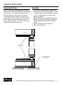
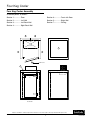
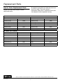
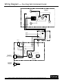
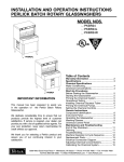
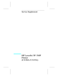
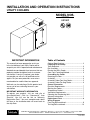
INSTALLATION and OPERATION INSTRUCTIONS
Utility Coolers
MODEL NOS.
US4KP
US10KP
IMPORTANT INFORMATION
This manual has been prepared to assist you
in the installation of your Utility Cooler and to
acquaint you with its operation and maintenance.
We dedicate considerable time to ensure that our
products provide the highest level of customer
satisfaction. If service is required, your dealer
can provide you with a list of qualified service
agents. For your own protection, never return
merchandise for credit without our approval.
We thank you for selecting a Perlick product and
assure you of our continuing interest in your
satisfaction
IMPORTANT WARRANTY INFORMATION
To register your product, visit our web site at
(www.perlick.com). Click on “Commercial”, then
“Service”. You will see the link to “Warranty
Registration Form”. You must complete and submit
this form or the installation date will revert back to
the ship Date.
Table of Contents
Cabinet Specifications.......................................... 2
Preparing for Assembly
Tools Required ..................................................... 3
Pre-Assembly........................................................ 3
Placing the Utility Cooler...................................... 3
Cam Lock Fastening Method.............................. 3
Assembling the Cooler
Preparing the Floor............................................... 4
Assembly............................................................... 4
Assembly Order-Four Keg Cooler......................... 5
Assembly Order-Ten Keg Cooler.......................... 6
General Information
Electrical Requirements........................................ 7
Starting the Cooler................................................ 7
Temperature Control............................................. 7
Ventilation Requirements...................................... 7
Cleaning the Condensing Unit.............................. 7
Warranty Information............................................ 7
Replacement Parts.............................................. 8
Wiring Diagrams
Four Keg Self-contained....................................... 9
Ten Keg Self-contained....................................... 10
8300 West Good Hope Road • Milwaukee, WI 53223 • Phone 414-353-7060 • Fax 414-353-7069
Toll Free 800-558-5592 • E-Mail: [email protected] • www.Perlick.com
Form No. Z2026
Rev 01.28.09
Installation and Operating Instructions
Sizes and Specifications, Utility Coolers - Self Contained
MODEL NOS.
US4KP
US10KP
Keg Capacity
4
10
Length
47" (1194)
93" (2362)
Depth
47" (1194)
47" (1194)
Height
DIMENSIONS
EXTERIOR
(mm)
77" (1956)
79" (2007)
Condensing Unit
1/3
1/2
full load amps
8.5
10.2
max. fuse
15
15
700 (318)
1150 (522)
shipping weight lbs. (kg)
exterior
Floor: Stucco galvanized steel. Roof, Walls & Doors: Stucco galvanized steel painted grey.
interior
Floor: 16 gauge slip resistant stainless steell. Roof, Walls & Doors: 26 gauge stucco
galvanized steel.
electrical
115 V, 60 Hz. 1ph AC. Junction box provided.
plumbing
Evaporator condensate drains through access hole in wall. 20" x 1/2" I.D. drain line provided.
refrigeration
R134a refrigerant.
insulation
4" UL Class 1 urethane foam. Flame Spreading Rate: 25 or less.
Smoke Develop Rating: 450 or less.
DOORS
Flush-mounted with cam-lift chrome hinges, automatic door closer, magnetic gaskets, chrome pull handle.
Standard right hinged. Door size: 30" W x 55" H.
features
Light “ON” indicator in door. Light switch and fixture installed on evaporator. Thermometer furnished loose.
optional accessories
• Foor rack
4”
23 1/2”
CL
14”
11”
• Keg shelf kit
TOP
VIEW
14”
4”
39”
47”
39”
INSIDE
INSIDE
REFRIGERATION
SLEEVE
CL
11” 14”
TOP
VIEW
14”
4”
28”
33 1/2”
28”
INSIDE
DOOR
OPENING
23 1/2”
REFRIGERATION
SLEEVE
44”
9 1/2”
4”
85” INSIDE
4”
JUNCTION
BOX
INSIDE
DOOR
OPENING
JUNCTION
BOX
21”
93”
9 1/2”
LIGHT BULB
W/GUARD
47”
32 3/4”
9”
15”
24 1/2”
30”
4”
4”
8”
LIGHT BULB
W/GUARD
12”
THERMOSTAT
7”
7”
CL
CL
17”
77”
FRONT
VIEW
4”
67”
INSIDE
END
VIEW
4 KEG COOLER
1”
REF
32 3/4”
79”
39”
51 1/4”
4”
67”
FRONT
VIEW
51 1/4”
END
VIEW
10 KEG COOLER
Perlick is committed to continuous improvement. Therefore, we reserve the right to change specifications without prior notice.
Form No. Z2026
Rev 01.28.09
2
Preparing the Cabinet for Use
Tools Required
■
■
■
■
■
■
■
■
The Cam Lock Fastening Method
Tape Measure.
Chalk Line.
Caulking Gun.
Caulk (provided).
Clam Lock Wrench (provided).
Level.
Screw Driver.
Shims.
This utility cooler utilizes the cam-lock fastening
method. (See illustration on below.)
Insert the cam lock wrench into the lock before the
panels are pushed together. Turn the handle Cam
Hole counterclockwise as far as it will go to fully
cock the
cam. Note: The cam must be fully cocked to
assure proper locking. The panels should then be
pushed together tightly and locked by turning the
wrench clockwise.
Pre-Assembly
Some panels have been protected with a strippable film to prevent surface damage. Remove this
film before assembly. It is very difficult to remove it
from the panel edges after panels have been joined
together. Note: Do not store panels with protective
film in sunlight or high temperature areas for an
extended period of time.
Plugs are provided to insert in cam-lock holes after
final assembly.
CAM
CAM
HOLE
Placing the Utility Cooler
This utility cooler should not be installed tight
against any building or adjacent cooler wall. A
minimum of two inches must be provided for air
circulation. Shims for leveling the floor must
also be incorporated into overall height and
clearance requirements.
Remote Units: A minimum four inch clearance is
required between the top of the utility cooler
and the ceiling of the building in which it is being
installed.
Self-contained Units: Sufficient clearance above the
cooler must be allowed for ceiling panel
and condensing unit installation. For ventilation
requirements, see page 7.
Perlick is committed to continuous improvement. Therefore, we reserve the right to change specifications without prior notice.
3
Form No. Z2026
Rev 01.28.09
General Information
Preparing the Floor
Assembly
Snap a chalk line on the building floor to establish
cooler location. Place floor panel(s) on the floor and
check for level. A level floor is essential to ensure
that vertical panels will be plumb. If shimming
is required to level the sections, the shims must
extend under the entire section, not just the edges.
Shims should be used at each end, at all wall
seams, and at each floor seam. They should not be
spaced further than 24 inches apart.
1. Place (do not slide) all sections into position.
2. Each panel is numbered on the edge. For a four
keg cooler, follow the assembly order on page
5. For a ten keg cooler, the assembly order
appears on page 6.
Note: If ceiling height in building is restricted,
panel(s) can be carried through the door opening and placed into position from inside the
cooler.
3. Install cap plugs in all cam-lock holes.
4. Seal cooler to the floor.
CEILING
KEEP GASKETS
OUT OF GROOVE
SEAL COOLER TO FLOOR
AFTER UNIT IS LEVEL AND
ASSEMBLED
FLOOR PANEL
FLOOR
Perlick is committed to continuous improvement. Therefore, we reserve the right to change specifications without prior notice.
Form No. Z2026
Rev 01.28.09
4
Four Keg Cooler
Four Keg Cooler Assembly
Assemble panels as follows:
Section 1:............... Floor
Section 6:............... Front with Door
Section 2:............... Left Wall
Section 5:............... Right Wall
Section 3:............... Left Back Wall
Section 7:............... Ceiling
Section 4:............... Right Back Wall
3
4
UNIT
COOLER
1
5
2
FLOOR
6
PANEL NO.#’S
7
FRONT VIEW
Perlick is committed to continuous improvement. Therefore, we reserve the right to change specifications without prior notice.
5
Form No. Z2026
Rev 01.28.09
Ten Keg Cooler
Ten Keg Cooler Assembly
Assemble panels as follows:
Section 1 & 2:......... Floor-Section
Section 7:............... Door Section
Section 3:............... Left Wall
Section 8:............... Left Front Panel
Section 4:............... Left Back Wall
Section 9:............... Celing Panel with
Evaporator Housiing
Section 5:............... Right Back Wall
Section 10:............. Celing Panel
Section 3A:............. Right Wall
Section 6:............... Right Front Wall
4
5
PANEL NO.#’S
9
UNIT
10
COOLER
3
3A
2
1
COOLER
6
8
7
10
9
FRONT VIEW
Perlick is committed to continuous improvement. Therefore, we reserve the right to change specifications without prior notice.
Form No. Z2026
Rev 01.28.09
6
General Information
Electrical Requirements
There should be nothing on or around the machinery compartment area which will restrict the flow of
room temperature air to the condenser or over the
compressor.
The package unit must be installed so that the wiring conforms to, and is in accordance with National
and Local Electrical Codes. (See Condensing Unit
Data Plate for Electrical Specifications.
CAUTION: Do not attempt to operate the condensing unit on any other power source than that listed
on the unit data plate. See appropriate wiring diagram on pages 9, 10 or 11.
Compressor H.P.
Natural
Circulation Cu.
Ft. Room Volume
Needed
Forced Air
Circulation C.F.M.
Fresh Air Entering
Room
1/3 to 1/2
600
220
Cleaning the Condensing Unit
Starting The Cooler
Inspect the machinery compartment every 60 days.
A heavy accumulation of dirt and/or grease on
the front of the condensing unit (radiator) must be
cleaned off with a stiff brush or vacuum cleaner. Be
careful not to bend the aluminum fins on the condensing unit.
Allow the empty utility cooler to operate 24 hours
for a settling-out period before use.
Temperature Control
The temperature control is located on the evaporator housing. It is factory adjusted to maintain a
temperature of approximately 34° F. cut out and
40° F. cut in. Cut out temperatures lower than 34°F.
are not advisable as excessive frost may accumulate on the evaporator.
Warranty
This Utility Cooler is fully warranted against defects
in both material and workmanship for a period
of one (1) year from date of sale. Defective parts
must be returned to Perlick freight prepaid. All
parts found to be defective upon inspection will be
replaced on a no-charge basis, F.O.B. our factory.
Perlick is not responsible for parts damaged by
alteration, unauthorized service, accident or abuse.
All costs incident to replacement, including labor,
refrigerant, and/or loss of sales are incidental to
this warranty and must be borne by the user.
If excessive frost does accumulate, the unit is
operating at too cold a temperature. To defrost the
evaporator, turn off the electrical power to the condensing unit or turn the control to a warmer position to allow the fan motor to defrost it. The control
should then be reset to a temperature that will not
ice up the evaporator. A plastic drain hose should
be attached to the drain pan of the evaporator and
routed through the wall panel. A receptacle should
be provided for accumulated condensing water or
connect to a building drain facility.
Ventilation Requirements
Air-cooled units must be furnished with sufficent
ventilation to maintain their efficiency. The table
at right indicates the minimum room size/cubic
footage, only the space above the condensing
unit can be used. When the room size is below
minimum, some type of forced ventilation must
be provided.
Perlick is committed to continuous improvement. Therefore, we reserve the right to change specifications without prior notice.
7
Form No. Z2026
Rev 01.28.09
Replacement Parts
How
to Order Replacement Parts
Be prepared to provide the model and serial number of the cooler. The serial number is
printed on a label which is attached to the inside
wall, adjacent to the evaporator housing.
Contact your local Perlick dealer to order
replacement parts.
SELF-CONTAINED UTILITY COOLERS
FOUR KEG
Ten KEG
Description
Part Number
Compressor Only
Description
57499
Compressor Only
Part Number
57860
Condensing Unit Fan Motor
57513
Condensing Unit Fan Motor
C15250A2
Condensing Unit Fan Blade
C3150-3
Condensing Unit Fan Blade
C15250A3
Evaporator Coil Assembly
57861
Evaporator Coil Assembly
57872
E xpansion Valve
57877
E xpansion Valve
57877
Temp. Control (two-wired)
57891
Temp. Control (two-wired)
57891
all model UTILITY COOLERS
Description
Switch
Part Number
Description
57878
Light Bulb
C31358
Bulb Guard
C25969-1
Part Number
Evaporator Fan Guard
57875
Plug Button
57882
Door Sill
57883
Thermometer
57879
Door Closure
57884
Hinged Door Assy.
57880
Light Indicator
57858
Gasket-Door Assy.
57881
Hinge
57885
Evaporator Fan Motor
57873
Handle
57886
Evaporator Fan Blade
57874
Door Wiper Gasket
57908
Perlick is committed to continuous improvement. Therefore, we reserve the right to change specifications without prior notice.
Form No. Z2026
Rev 01.28.09
8
Wiring Diagram — Four Keg Self-Contained Cooler
CAPACITOR
COMPRESSOR
TERMINALS
GREEN
C
1
BROWN
WHITE
L1
S
2
R
L2
RELAY
OVERLOAD
FAN
GREEN
BLACK
WHITE
SWITCH
GREEN
LIGHT
WHITE
BLACK
WHITE
(ELECTRONIC)
THERMOSTAT
(4 MIN. “ON” DELAY)
BLACK
BROWN
WHITE
EVAPORATOR
FAN MOTORS
(ALTERNATE)
THERMOSTAT
(STANDARD)
BLACK
BROWN
Perlick is committed to continuous improvement. Therefore, we reserve the right to change specifications without prior notice.
9
Form No. Z2026
Rev 01.28.09
Wiring Diagram — Ten Keg Self-Contained Cooler
1
2
CAPACITOR
M
RELAY
RED
OVERLOAD
BLUE
3
1
C
YELLOW
WHITE
BROWN
GREEN
FAN
CONDENSER
L
5
S
R
COMPRESSOR
TERMINALS
GREEN
BLACK
WHITE
SWITCH
GREEN
LIGHT
WHITE
BLACK
WHITE
(ELECTRONIC)
THERMOSTAT
(4 MIN. “ON” DELAY)
BROWN
BLACK
WHITE
EVAPORATOR
FAN MOTORS
(ALTERNATE)
THERMOSTAT
(STANDARD)
BLACK
BROWN
Perlick is committed to continuous improvement. Therefore, we reserve the right to change specifications without prior notice.
Form No. Z2026
Rev 01.28.09
10
Perlick is committed to continuous improvement. Therefore, we reserve the right to change specifications without prior notice.
11
Form No. Z2026
Rev 01.28.09
8300 West Good Hope Road • Milwaukee, WI 53223 • Phone 414-353-7060 • Fax 414-353-7069
Toll Free 800-558-5592 • E-Mail: [email protected] • www.Perlick.com
Form No. Z2026
Rev 01.28.09