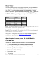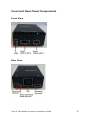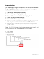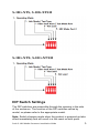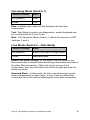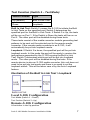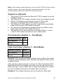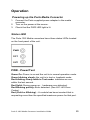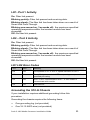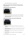
1
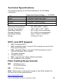
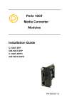
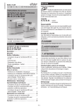
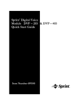
Perle 10G
Media Converters
Installation Guide
S-10G-STS
S-10G-XTS
S-10G-XTX
S-10G-XTSH
S-10G-XTXH
P/N 5500325-10
Overview
This document contains instructions necessary for the installation
and operation of the Perle S-10G Standalone Media Converters.
The Perle S-10G Standalone Media Converters are 10 Gigabit
Media Converters with two pluggable transceiver ports. The S-10G
supports low power transceivers, whereas the S-10G-XTSH and
the S10G- XTXH support high power (power level 4) transceivers.
Model
Port 1
Port 2
S-10G-STS
SFP+
SFP+
S-10G-XTS
XFP
SFP+
S-10G-XTSH
XFP
SFP+
S-10G-XTX
XFP
XFP
S-10G-XTXH
XFP
XFP
Note: The S-10G Media Converter must be populated with two 1G
fiber/copper modules to operate at 1G.
Note2: When used with 1G modules, the S-10G does not support
the Loopback Auto Detect feature.
Visit Perle’s web site for the most up to date Installation guides,
models and specifications: http://www.perle.com/
Getting to know your S-10G Media
Converter
Your S-10G Media Converter consists of the following items:
•
S-10G chassis with two pluggable transceiver ports
•
Grounding screws (for improved chassis grounding)
•
Country specific power adapter
•
Power cord strain relief clip
•
Four rubber feet
•
This guide
Perle S- 10G Media Converter Installation Guide
2
Front and Rear Panel Components
Front View
Rear View
Perle S- 10G Media Converter Installation Guide
3
Installation
The default switch setting (all switches in the UP position) will work
for most installations. These are the steps required to configure
the Perle S-10G standalone media converter:
1. Set the DIP switch settings.(optional)
2. Connect the grounding lug. (optional)
3. Connect the power cord strain relief clip. (optional)
4. Insert the fiber or copper modules.
5. Connect the fiber or copper cables.
6. Using the Perle supplied power adapter, plug the power cord
into the power cord connector at the rear of the chassis.
7. Plug the other end of the power adapter into an appropriate
power outlet.
Note: The S-10G Chassis should always be grounded for safe and
proper operation. See Grounding the S10-G Chassis
S-10G-STS
P/N 5500325-10
S-10G-XTS, S-10G-XTSH
S-10G-XTX, S-10G-XTXH
DIP Switch Settings
The DIP switches are accessible through the opening in the side
of the enclosure. The function of the DIP switches varies by
model, so please refer to the appropriate model.
Note: Switch changes made when the product is powered up take
effect immediately and will result in a link reset on both ports.
Perle S- 10G Media Converter Installation Guide
5
Operating Mode (Switch 1)
Switch Position
Mode
Up (default)
Data
Down
Test
Data: In Data mode, data will flow between the two fiber
connections.
Test: Test Mode is used to run diagnostics, enable loopback and
for running the Built In Link Tests.
Note: The Operation Mode (Switch 1) affects the function of DIP
Switches 2 and 3.
Link Mode (Switch 2 – Data Mode)
Switch Position
Mode
Up (default)
Smart Link Pass-Through Mode
Down
Standard Mode
Smart Link Pass-Through: In this mode, the link state on one
fiber connection is directly reflected through the media converter to
the other fiber connection. If fiber link is lost on one of the
connections, then the other fiber link will be brought down by the
media converter.
Standard Mode: In this mode, the links can be brought up and
down independently of each other. A loss of link on either fiber
connection can occur without affecting the other fiber connection
Perle S- 10G Media Converter Installation Guide
6
Test Function (Switch 2 – Test Mode)
Switch Position
Type
Up (default)
Built In Link Test
Down
Loopback
Built In Link Test: Switch 2 causes the S-10G to initiate the Built
In Link Tests on the specified port. Switch 3 determines the
specified port for the Built In Link Tests. If Switch 3 is Up, the tests
will be run on Port 1. If the Switch is Down the tests will be run on
Port 2. The other port will be disabled during these tests.
These tests consist of the media converter module generating test
patterns to be sent out the selected port to the remote media
converter. If the remote media converter is an S-10G, it will
automatically be put into loopback mode.
Loopback: If Switch 2 is down, the specified port will be put into
loopback mode. In this mode the port will be ready to receive the
test patterns generated by the S-10G running the Built in Link
Test. Switch 3 determines which port will be put into loopback
mode. The other port will be disabled during the tests. If the
remote device is also an S-10G media converter, this unit does not
need to be put into test mode and there is no need to set the
loopback switch. This will be taken care of by the Auto Loopback
feature.
Illustration of the Built In Link Test / Loopback
Local S-10G Configuration
Test Mode (Switch 1 – Down)
Test Fuction (Switch 2 –Up)
Remote-S-10G Configuration
All switches in the Up position
Perle S- 10G Media Converter Installation Guide
7
Note: If the remote media converter is not a Perle S-10G then the remote
media converter will need to be put into loopback mode. See the
documentation that came with that media converter.
Sequence of Events
1. The Local S-10G sends the Remote S-10G a signal to go into
loopback mode.
2. The Remote S-10G media converter turns on loopback mode.
3. Built In Test data is sent from the Local S-10G media
converter to the Remote S-10G media converter.
4. The Remote S-10G media converter loops the received data
back to the Local S-10G media converter.
5. Any test errors detected are displayed with the LEDs on the
front of the Local S-10G media converter.
6. The Built in Link Tests continue to run until Switch 1 on the
Local S-10G media converter is set to Data mode.
Port Selection (Switch 3 – Test Mode)
Switch Position
Port
Up (default)
1
Down
2
Fiber Fault Alert (Switch 3 – Data Mode)
Switch Position
Mode
Up (default)
Enabled
Down
Disabled
Enabled: If the media converter detects a loss of fiber, the media
converter will immediately notify the fiber link partner that an error
condition exists.
If the remote media converter is set up for Fiber Fault Alert (FFA)
Enabled and the local media converter is set up with Smart Link
Pass-Through, a loss of fiber link on either the transmit or receive
line will be passed through to the other fiber connection.
Disabled: The media converter will not monitor for fiber fault.
Perle S- 10G Media Converter Installation Guide
8
Illustration of the FFA feature
Media Converter A Configuration
Link Mode–Standard Mode
Fiber Fault Alert
Media Converter B Configuration
Link Mode–Smart Link Pass through Mode
Fiber Fault Alert
Sequence of Events
1. Media Converter A loses fiber connection (RX).
2. Media Converter A notifies the remote Media Converter that
there is a fault on the Link.
3. Media Converter B detects loss of fiber link on receiver RX.
4. Media Converter B turns off transmitter (TX).
EDC AutoDetect Mode (Switch 4 and Switch 5)
SFP+ Models Only
Switch Position
Mode
Up (default)
On
Down
Off
On: When AutoDetect Mode is turned On, the S-10G media
converter will establish the linear or limiting settings based on the
contents of the EPROM on the module and the module type.
Off: When AutoDetect Mode is turned OFF, the S-10G media
converter will select the alternative mode that was established by
the determination above.
Perle S- 10G Media Converter Installation Guide
9
Operation
Powering up the Perle Media Converter
1. Connect the Perle supplied power adapter to the media
converter.
2. Turn on the power at the source.
3. Check that the PWR LED light is lit.
Status LED
The Perle 10G Media converters have three status LEDs located
on the front panel of the unit.
PWR - Power/Test
Green On: Power is on and the unit is in normal operation mode.
Green blinking slowly: the unit is in test or loopback mode.
Red blinking slowly while in Test mode: indicates an error
within the last second.
Red Solid: During power up - hardware error detected.
Red Blinking quickly: Error detected. (See LK1 LK2 Error
Codes).
Red (Solid or Blinking) – A module has been inserted that is
requesting more than the specified maximum power for that port.
Perle S- 10G Media Converter Installation Guide
10
LK1- Port 1 Activity
On: Fiber link present.
Blinking quickly: Fiber link present and receiving data.
Blinking slowly: The fiber link has been taken down as a result of
Smart Link Pass-Through.
Blinking one second on, 3 seconds off: the maximum specified
operating temperature within the inserted module has been
exceeded.
Off: No fiber link present.
LK2 – Port 2 Activity
On: Fiber link present.
Blinking quickly: Fiber link present and receiving data.
Blinking slowly: The fiber link has been taken down as a result of
Smart Link Pass-Through.
Blinking one second on, 3 seconds off: the maximum specified
operating temperature within the inserted module has been
exceeded.
Off: No fiber link present.
LK1 LK2 Error Codes
LK1
LK2
Meaning
Off
Off
Incompatible SFP+ or XFP or speed mismatch on SFP+
Off
On
Power Budget exceeded – XFP’s requesting more power than
specified port rating.
On
Off
SFP+ or XFP communication error – S-10G unable to
communicate with module
On
On
Internal Error
Grounding the S10-G Chassis
If your installation requires additional grounding follow this
procedure.
Grounding the chassis requires the following items:
•
One grounding lug (not provided)
•
One 18-12 AWG wire (not provided)
Perle S- 10G Media Converter Installation Guide
11
•
Cross-head screwdriver (not provided)
Note: For your safety, when installing this equipment, always
ensure that the chassis ground connection is installed first and
disconnected last.
Attaching the Grounding Lug
1. Attach the grounding lug to one end of an 18-12 AWG wire.
2. Attach the grounding lug to the chassis and secure with the
grounding screw(s).
Attaching the Power Cord Strain Relief Clip
1. Feed the power cord through the opening in the power cord
relief clip.
2. Attach the power cord relief clip to the chassis and secure with
the provided screw.
3. Plug the power cord into the AC power connector at the rear
of the chassis.
4. Plug the other end of the power cord into an appropriate
power outlet.
Perle S- 10G Media Converter Installation Guide
12
Troubleshooting
General
Ensure power is supplied to the media converter – use of
the Perle supplied power adapter is highly recommended.
Ensure that the SFP+ or XFP modules are of the same
speed and are operating properly.
Ensure both devices on either end of each fiber are
compatible.
For fiber connections, ensure the RX and TX have been
reversed between the two media converters.
No connectivity
If unable to get full connectivity with all DIP switches in the UP
position, this procedure is recommended for troubleshooting.
1. Built In Link Test: Set Switch 2 to the Up position.
2. Set Switch 3 to the Up position to test port 1 or Switch 3 to the
Down position to test Port 2.
3. Loopback: If the remote media converter is a Perle S-10G,
then the Local Perle S-10G media converter will signal the
Remote media converter to go into loopback mode. (If the
remote media converter is not a Perle S-10G, then the remote
media converter will need to be put into Loopback Mode (See
the User’s Guide that came with that media converter).
4. Test Data will be sent from the local S-10G to the Remote
media converter.
5. If the PWR LED on the Local S-10G turns red or blinks red on
a repeated basis, the fiber connection may require further
testing.
6. If the PWR LED on the Local S-10G stays green after several
seconds of testing, then the link is passing the Built In Link
Test. Proceed to testing the other link.
P/N 5500325-10
Module Temperature Protection
Every S-10G comes equipped with an internal fan to provide
cooling to the unit. However, if any of the modules are operating
above their specified maximum operating temperature, the S-10G
will reduce the power to these modules. The S-10G will continue
to monitor the operating temperature of the unit until the
temperature is below the maximum operating temperature and
then the S-10G will return the modules to normal operating.
Loopback Auto Detect
Perle S-10G media converters have the ability to automatically put
remote Perle S-10G media converters in loopback mode. This
allows the remote S-10G media converter to be located in distant
or inaccessible locations. The remote S-10G will remain in
loopback mode as long as the tests are in progress.
Note: Depending on the manufacturer some copper cabling may not
support our Loopback Auto Detect feature, however Loopback Mode can
always be obtained by setting switch 2 to the down position on your
Perle Media converter.
Perle S- 10G Media Converter Installation Guide
14
Technical Specifications
The following applies to all Perle Standalone S-10G Media
converters.
Power Input/Consumption
9-30VDC
1.0A Max, 600mA at 12VDC
1.2A Max, 800mA at 12VDC
1.5A Max, 1.0A at 12VDC
1.5A Max, 1.0A at 12VDC
2.0A Max, 1.4A at 12VDC
STS
XTS
XTX
XTSH
XTXH
Operating Temperature:
Storage Temperature:
Operating Humidity:
Storage Humidity:
Operating Altitude:
Weight:
0°C -50°C (32°F - 122°F)
-25°C -70°C (-13°F -158°F)
5% to 90% non-condensing
5% to 95% non-condensing
Up to 3,048 m (10,000 ft)
0.38 kg (0.3 lbs.)
SFP+ and XFP Support
•
•
•
•
•
•
•
MSA Compliant SFP+
MSA complaint Class 1,2 and 3 XFP modules for the S-10GXTX and S-10G-XTS
MSA complaint Class 1,2,3 and 4 XFP modules for the S10G-XTXH and S-10G-XTXSH
1G copper modules
1G fiber modules
SFP+ supports Cx1 (direct attach) interfaces
XFP supports CX4 modules
Fiber Cabling Requirements
MM:
50/125 microns
62.5/125 microns
SM:
9/125 microns
Note: Please refer to the product page on the Perle website for
the most up to date specifications.
http://www.perle.com/
Perle S- 10G Media Converter Installation Guide
15
Compliance Information
FCC
This product has been found to comply with the limits for a Class A digital device,
pursuant to Part 15 of the FCC rules. These limits are designed to provide
reasonable protection against harmful interference when the equipment is operated
in a commercial environment. This equipment generates, uses, and can radiate
radio frequency energy and, if not installed and used in accordance with the
instructions in this Guide, may cause harmful interference to radio communications.
Operation of this equipment in a residential area is likely to cause harmful
interference, in which case the user will be required to correct the interference at
his/her own expense.
EN 55022 Class A
WARNING This is a Class A product. In a domestic environment this product may
cause radio interference in which case the user may be required to take adequate
measures.
EN 55024 Class A
Contacting Technical Support
Contact information for the Perle Technical Assistance Center
(PTAC) can be found at the link below. A Technical Support Query
may be made via this web page.
www.perle.com/support_services/support_request.shtml
Warranty / Registration
Perle’s standard Lifetime Warranty provides customers with return
to factory repairs for Perle products that fail under the conditions of
the warranty coverage. Details can be found at:
http://www.perle.com/support_services/warranty.shtml
Copyright © 2012 Perle Systems Limited
All rights reserved. No part of this document may be reproduced or used in any form
without written permission from Perle Systems Limited.
Perle S- 10G Media Converter Installation Guide
16