1
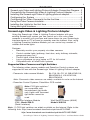
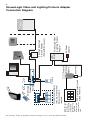
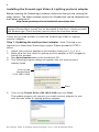
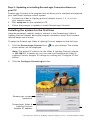
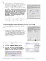
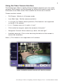
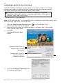
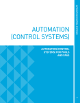
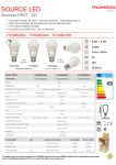
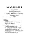
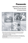
ScreenLogic®
Video & Lighting Protocol
Adapter
User’s and Installation Guide
ScreenLogic Video & Lighting Protocol Adapter User’s and Installation Guide
i
ScreenLogic® Video & Lighting Protocol Adapter kit contents
The following items are included in the kit.
Kit contents
•
•
•
•
•
ScreenLogic Video & Lighting Protocol Adapter (P/N 520854Z)
AC/DC power adapter
RJ45 cable
DB9M to RJ45 adapter
User’s and Installation Guide (this manual)
Technical Support
Sanford, North Carolina (8 A.M. to 5 P.M. ET)
Moorpark, California (8 A.M. to 5 P.M. PT)
Phone: (800) 831-7133 - Fax: (800) 284-4151
Related manuals - Download the IntelliTouch ScreenLogic User’s Guide
(P/N 520493) at:
http://www.pentairpool.com/siteimages/ScreenLogic_Users_Guide.pdf
FCC Regulatory Safety Notice - This equipment has been tested and found to comply with the
limits for a Class B digital device, pursuant to Part 15 of the FCC Rules. These limits are designed to
provide reasonable protection against harmful interference in a residential installation. This equipment
generates, uses and can radiate radio frequency energy and, if not installed and used in accordance
with the instructions, may cause harmful interference to radio communications. However,
there is no guarantee that interference will not occur in a particular installation. If this equipment does
cause harmful interference to radio or television reception, which
can be determined by turning the equipment off and on, the user is encouraged to try to correct the
interference by one or more of the following measures:
• Reorient or relocate the receiving antenna.
• Increase the separation between the equipment and receiver.
• Connect the equipment into an outlet on a circuit different from that to which the receiver is
connected.
• Consult the dealer or an experienced radio/TV technician for help.
• Modifications not expressly approved by the party responsible for FCC compliance could
void the user’s authority to operate the equipment.
IC Regulatory Notice
Operation is subject to the following two conditions: (1) this device may not cause interference, and
(2) this device must accept any interference, including interference that may cause undesired
operation of the device.
© 2008 Pentair Water Pool and Spa, Inc. All rights reserved.
1620 Hawkins Ave., Sanford, NC 27330 • (919) 566-8000
10951 West Los Angeles Ave., Moorpark, CA 93021 • (800) 553-5000
IntelliTouch®, ScreenLogic® and Pentair Water Pool and Spa® are registered trademarks of Pentair Water Pool
and Spa, Inc. and/or its affiliated companies in the United States and/or other countries. Unless noted, names
and brands of others that may be used in this document are not used to indicate an affiliation or endorsement
between the proprietors of these names and brands and Pentair Water Pool and Spa, Inc. Those names and
brands may be the trademarks or registered trademarks of those parties or others.
P/N 520936 - Rev A - 03/03/2008
ScreenLogic Video & Lighting Protocol Adapter User’s and Installation Guide
1
Contents
ScreenLogic Video and Lighting Protocol Adapter Connection Diagram . 2
Connecting the ScreenLogic Video & Lighting Protocol Adapter ............ 3
Installing the ScreenLogic Video & Lighting protocol adapter ................. 4
Configuring the System ....................................................................... 5
Configuring the Video Camera(s) for the first time ................................ 6
Using the Video Camera Interface ......................................................... 9
Installing the Lights for the first time ................................................... 10
Using the Lights Interface ................................................................... 13
ScreenLogic Video & Lighting Protocol Adapter
Using the SceenLogic Video & Lighting Protocol adapter with your
existing ScreenLogic system you can control up to four color video
cameras to monitor your pool/spa and home areas via your ScreenLogic
interface device or PC at home or remotely over the Internet. Also, using
a Lighting Powerline Interface Module you can control any number of
outside and inside lights.
Features:
•
Remotely monitor your property via video cameras
•
Control outside lights (pathway, front door, entry hallway, stairwells,
garage entryway, etc.)
•
Control lights inside the home
•
Log on anywhere via your laptop or PC for full control
•
Compatible with all IntelliTouch systems
Supported Video Cameras and Light Switches
The following video camera models and Powerline Control systems are
supported for use with the ScreenLogic Video & Lighting Protocol adapter:
- Panasonic video camera Models:
BL-C1A, BL-C111A, BB-HCM311A,
BB-HCM331A, KX-HCM110A,
BB-HCM381A
Note: Panasonic video cameras are widely available for sale on the Internet
- Powerline Control Systems, PulseWorx PCS models:
Note: PCS light switches *
are compatible with
incondescent light bulbs
only. Lights with florescent
light bulbs cannot be
used.
Powerline Interface Module
(PIM) - Model PIM-R
(Serial Interface)
Wall Switch Dimmer (600W)
Model # WS1D6
Note: (*) PCS light switches are widely available on the Internet. Refer to the
following links: http://www.hometech.com/brains/upb.html#PO-PIMR
http://www.hometech.com/modules/upb.html#PO-WS1D6W
ScreenLogic Video & Lighting Protocol Adapter User’s and Installation Guide
Note: PSC light
switches are
compatible with
incondescent
light bulbs only.
Lights with
florescent light
bulbs cannot be
used.
Camera
1 2 3 4
PCS Light switch(s) found
around the home
For additional cameras
(max qty. 4) an optional
Network switch is
required.
1 2 3 4
ScreenLogic
Wireless
Router
WAN
ScreenLogic Video & Lighting Protocol Adapter User’s and Installation Guide
DB9M / RJ45
Powerline
Interface
Module
AC Power
adapter
LAN
COM 1 ScreenLogic Video
& Lighting Protocol
Adapter
Existing ScreenLogic
Protocol Adapter
(Pentair Brick: xx-xx-xx)
2
ScreenLogic Video and Lighting Protocol Adapter
Connection Diagram
3
Connecting the ScreenLogic Video & Lighting Protocol
Adapter
The following describes how to connect the Video & Lighting Protocol adapter
to an existing ScreenLogic system.
1.
Connect the provided RJ45 (CAT5) cable to an available port (1, 2, 3,
or 4) on the ScreenLogic wireless router. Connect the other end of the
cable to the LAN port on the Video & Lighting Protocol adapter (see
diagram on page 2).
2.
Lights cable connection: Connect an RJ45 (CAT5) cable to the
COM 1 port on the adapter. Connect the other end of the cable to the
DB9M/RJ45 adapter. Connect the DB9M/RJ45 adapter to the RS-232
connector that is connected to the UPB Powerline Interface Module
(PIM). See diagram on page 2.
3.
Camera cable connection: Connect AC power plug to the video
camera(s). Connect the RJ45 camera cable to port 1, 2, 3, or 4 on the
ScreenLogic wireless router (see diagram on page 2).
If additional cameras are being installed, a Network Switch can be
used to provide available ports. ScreenLogic supports a maximum of
four cameras (see diagram on page 2).
ScreenLogic Video & Lighting Protocol Adapter Name
The Video & Lighting Protocol adapter system name is identified on the
screen as:
Pentair: xx-xx-xx (where xx-xx-xx are the last six (6) digits of the unit’s serial
number which can be found on a sticker on the adapter). The name is
displayed on the ScreenLogic Connect dialog as shown below:
Check this box to save the
current login information
Pentair Brick
(192.168.2.2.:80) is the
existing ScreenLogic
Protocol Adapter IP address.
Do not configure this
adapter.
ScreenLogic Video & Lighting
Protocol Adapter name
ScreenLogic Video & Lighting Protocol Adapter User’s and Installation Guide
4
Installing the ScreenLogic Video & Lighting protocol adapter
Before installing the ScreenLogic software, make sure that you are running the
latest version. The latest software version for ScreenLogic can be obtained from
the Pentair website at:
http://www.pentairpool.com/techinfo/instructions.htm
Note: If an existing ScreenLogic system is not present, please install the
standard ScreenLogic system first as described in the User’s Guide provided
with ScreenLogic. Once installed, please follow the directions below.
Follow the two step process to install the ScreenLogic Video & Lighting
protocol adapter:
Step 1: Updating the small protocol adapter - Note: This step is not
required for a brand new ScreenLogic system. Please proceed to STEP 2
below.
1. Attach your protocol adapter to the wireless router port 1, 2, 3, or 4.
2. Make sure that the Video & Lighting protocol adapter is NOT plugged in
during this process.
4. Run pentairupdate.exe on the installation CD.
5. The following program dialog will appear with the small protocol
adapter listed.
Click on the
Pentair Brick
(192.168.2.2:80)
Start
5.
Click on the Pentair Brick (192.168.2.2:80) and click Start.
The update program will convert your small protocol adapter for use
with the new Video & Lighting protocol adapter.
ScreenLogic Video & Lighting Protocol Adapter User’s and Installation Guide
5
Step 2: Updating or installing ScreenLogic Connect software on
your PC
ScreenLogic Connect is the program that will allow you to configure and operate
your IntelliTouch pool/spa control system.
1.
2.
3.
Connect the Video & Lighting protocol adapter to port 1, 2, 3, or 4 on
your wireless router.
Run setup.exe on the installation CD.
Follow the prompts to update or install ScreenLogic Connect.
Installing the system for the first time
Have the camera(s) cable(s) ready to connect to the ScreenLogic Video &
Lighting Protocol adapter during the program installation setup. Each camera
must be setup one at a time.
To setup the ScreenLogic Video & Lighting Protocol adapter for the first time:
1.
Click the ScreenLogic Connect icon
shown below will be displayed.
on your desktop. The screen
Note: The default IP address for the Video & Lighting Protocol adapter
is 192.168.2.3. If necessary, you can view and configure the Video &
Lighting Protocol Adapter IP settings by clicking the “Configure IP Info”
button.
2.
Click the Configure ScreenLogic button.
ScreenLogic system
password
ScreenLogic Video &
Lighting Protocol
Adapter IP address
ScreenLogic Video & Lighting Protocol Adapter User’s and Installation Guide
6
3.
The software will configure the smaller
ScreenLogic Protocol Adapter for use with
the Video & Lighting Protocol Adapter. A
“System Configuration Complete”
message box will be displayed. Click OK
to continue with the installation. Please be
patient while the Video & Lighting Protocol
adapter synchronizes the settings from the
IntelliTouch system for the first time. This
can take anywhere from 3 to 15 minutes
depending upon the complexity of your
IntelliTouch system.
Note: When synchronizing is complete, the
current system information is displayed in
the dialog box (see dialog on right).
Configuring the Video Camera(s) for the First Time
To configure the video camera(s) for the first
time:
1.
Connect the RJ45 camera cable to the
ScreenLogic Wireless Router port 1, 2, 3,
or 4 and plug in the camera. See page 2
for connection diagram. Please allow the
video camera 45 seconds to power up
before proceeding.
2.
Click the Configure Video button to
configure the camera.
3.
Click the Add New Camera button.
4.
Click the OK button on the message
dialog box. Ensure that the camera was
plugged in within the last 20 minutes.
ScreenLogic Video & Lighting Protocol Adapter User’s and Installation Guide
7
5.
Select the camera manufacture and model and click the OK button.
Note: Only configure
one camera at a time.
For example, connect
the first camera, then
configure it. Plug in the
second camera and
repeat.
6.
Select the installed video camera model to rename the camera and set
its IP address. The cameras IP address must be in the same subnet
range as your ScreenLogic Video & Lighting Protocol Adapter. The
default IP address for the ScreenLogic Video & Lighting Protocol
Adapter is 192.168.2.3 - It is recommended that you select a higher IP
address to avoid conflict on your network. For example, use
192.168.2.80 for camera No. 1, 192.168.2.81 for camera No. 2, etc.
7.
For additional cameras, click the Add New Camera button and repeat
steps 1 - 6.
8.
Click Done when finished. The Configuration setup dialog box will be
displayed.
ScreenLogic Video & Lighting Protocol Adapter User’s and Installation Guide
8
9.
Click the RED X box on the top right side of the dialog to exit the
Configuration setup dialog.
10. Click on the Video & Lighting Protocol adapter in the Local System
box, then click START.
Note: If the Video & Lighting adapter does not show up
under the Local Systems, you can manually type in the
adapter’s IP address in the System Name field. The
adapter’s default IP address is 192.168.2.3
11. Click the
Start ScreenLogic button
to start the ScreenLogic program.
ScreenLogic Video &
Lighting Protocol
Adapter address
Note: Please note it may take
a few minutes for the video
camera to complete its
configuration for the first time
before the video appears.
ScreenLogic Video & Lighting Protocol Adapter User’s and Installation Guide
9
Using the Video Camera Interface
The ScreenLogic Video & Lighting Protocol Adapter supports up to four video
cameras. Each camera can be accessed by clicking the camera’s name tab at
the bottom of the Video screen. Each camera has its own set of controls.
Camera controls include:
•
Full Screen: Monitor in full screen mode
•
Low, Med, High: Set the camera resolution
•
1,2,3,4,5,6,7,8: Preset camera positions (This feature is not supported
on the BL-C1A camera)
•
(-) (+) : Camera zoom out (-) and in (+) out *
•
Click inside the image to center the camera to that point *
•
Navigation Controls: Move camera up, down, left and right *
•
Installed camera(s): Click on the tab along the bottom of the screen to
access the camera(s).
Note: (*) This feature is not supported on all cameras.
Note: Available camera controls will vary by camera.
ScreenLogic Video & Lighting Protocol Adapter User’s and Installation Guide
10
Installing Lights for the first time
Have the Powerline Interface module ready to connect to COM 1 port on the
ScreenLogic Video & Lighting Protocol adapter during the program installation setup. Each light switch must be setup one at a time.
WARNING - All switches work must be installed by a licensed
electrician, and must conform to the National Electric Code and all
national, state, and local codes.
To install the PCS Light switches:
Note: PCS light switches are compatible with incondescent light bulbs only. Lights
with florescent light bulbs cannot be used.
1.
2.
3.
Click the ScreenLogic Connect icon
on your desktop. The
following screen will be displayed.
Be sure that the Video & Lighting adapter is selected and is populated
in the system name field.
Click the
Configure ScreenLogic
button.
System name xx-xx-xx
ScreenLogic system
password
ScreenLogic Video &
Lighting Protocol
Adapter address
4.
Click the Configure Lighting button
to configure the lights.
ScreenLogic Video & Lighting Protocol Adapter User’s and Installation Guide
11
5.
Click the Add New button.
6.
Press the light switch five (5) times in the ON position. The green LED
on the light switch will start blinking rapidly which indicates that the
light is ready to be configured. See page 2 for connection diagram.
7.
Click the OK button on the message dialog box.
8.
Rename the light in the “Name” box. Use a name that describes where
the light is located. Click the OK button. The light setup procedure will
take about one minute for each light fixture.
9.
To setup additional lights, click the Add New button and repeat
steps 6 - 9.
ScreenLogic Video & Lighting Protocol Adapter User’s and Installation Guide
12
10. Click Done when finished.
11. Click the RED X box on the top
right side of the dialog to exit the
Configuration setup dialog.
12. Select the Video & Lighting Protocol Adapter in the lower dialog box as
shown below.
13. Click the Start ScreenLogic button to start the ScreenLogic program.
ScreenLogic Video &
Lighting Protocol
Adapter address
14. Click the Lighting tab to access the LIGHTING screen.
ScreenLogic Video & Lighting Protocol Adapter User’s and Installation Guide
13
Using the Light Interface
The ScreenLogic light screen displays the following light(s) controls.
Click anywhere on the light bar to set
the light intensity
Click to switch
light OFF
Click to switch
light ON
ScreenLogic Video & Lighting Protocol Adapter User’s and Installation Guide
P/N 520936 - Rev A
ScreenLogic Video & Lighting Protocol Adapter User’s and Installation Guide