1
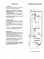
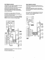
SYSTEM START-UP
Apply power to the system.
INSTALLATION INSTRUCTIONS
CP30 POOL-SPA SWITCHING SYSTEM
At the LX-30 Power Center, check that the POWER Status Light has turned on.
If the status light is not on, check the 3 amp circuit breaker which is located above
the faceplate. Tripped circuit breaker is indicated by a white tab. Push to reset.
Turn the FILTER PUMP Service Switch "ON" and " O F F to verify that pump is
operating.
Return FILTER PUMP Service Switch t o "TIMER" position, and activate filter
7ump using the FILTER TIMER Dial.
t the system incorporates a pool cleaner pump, activate pump using the
CLEANER TIMER Dial.
At the Remote Control, turn SPA Switch to "SPA position.
Check that Valve Actuators have rotated to correct positions. If either valve is
180" out of phase, flip toggle switch on rear of Valve Actuator from "ON1" to
"ON2" position.
Turn HEAT Switch to "SPA position, and check that heater has been activated.
Turn AUXl and AUX2 Switches "ON", and verify that auxiliary equipment has
been activated.
The system is now ready to be operated as desired.
IMPORTANT SAFETY INSTRUCTIONS
All wiring must be performed by a qualified electrician.
Basic safety precautions and local codes should
always be followed when installing and using this
electrical equipment.
READ AND FOLLOW ALL INSTRUCTIONS.
WARNING : To reduce the risk of injury, do not
permit children to use this product unless they are
closely supervised at all times.
SAVE THESE INSTRUCTIONS.
a PAC FA6 Company
Cornpool, Inc.
599 Fairchild Drive
Mountain View
California 94043
800-458-2201
http ://www.c0mpo01.com
SYSTEM OPTIONS
RECOMMENDED HYDRAULIC SCHEMATIC
POOL CLEANER :
For systems which incorporate a booster pump pool cleaner, it is possible to add a
mechanical time clock for programming the daily cleaning cycles.
Install 24-Hour Time Clock (model TMR-LX) into LX-30 faceplate at the
CLEANER TIMER location, and plug into circuit board at CLNR TIMER socket, in
accordance with instructions provided.
Install a Relay Kit (model RLY-LX) at the LX-30 Power Center in accordance
with instructions provided, and plug into circuit board at CLNR relay socket.
NOTE : It will not be possible to activate the pool cleaner unless the CP-30
Remote Control has been connected.
SPA WATERFALL CONTROL :
For systems where spa water level is higher than that of the pool, it is possible to
use either AUXl or AUX2 Switches at the Remote Control to rotate the return
valve to spa return position.
This creates an overflow (waterfall effect) from the spa into the pool, while the
system is in "pool mode". The effect will, however, cease whenever the system is
in "spa mode".
To enable this feature, install a Spa Waterfall Control (model RLY-WTRFL) at
the LX-30 Power Center in accordance with instructions provided.
FREEZE PROTECTION :
A Recirculating Freeze Sensor (model FPS-C) may be added to the system. It
will protect the plumbing and equipment from possible freeze damage by running
the filter pump whenever the temperature falls to approx. 41°F.
Install FPS-C in accordance with instructions provided, and connect to circuit
board at FRZ and GND screw terminals, in accordance with wiring diagram.
An Auxiliary Freeze Sensor (model FPS-AUX) may also be added to activate
auxiliary equipment (such as a jet pump) during potential freezing conditions.
Install FPS-AUX in accordance with instructions provided.
NOTE : It is advisable to inspect and test the freeze sensor(s) at least once
a year, preferably prior t o the onset of the freezing season. Testing can be
accomplished by immersing sensor in ice water.
Refer to Page 2 for Plumbing Requirements
HIGH-VOLTAGE WIRING
EQUIPMENT LOCATION
Select a convenient location to install the various components of the System.
All electrical equipment must be located five feet or more from the water's edge :
1.
2.
3.
LX-30 Power Center at the equipment site.
CVA-24 Valve Actuators at valves to be motorized.
CP-30 Remote Control at convenient location indoors or outside.
POWER CENTER
Select a convenient location (at the equipment site) to mount the LX-30 Power
Center. Ensure that the location is greater than 5 feet from the water's edge and
no further than 15 feet from any motorized valves (otherwise Valve Actuator cable
will need to be extended).
Mount the LX-30 on a flat surface using appropriate screws through the three
external mounting points located on the side of the enclosure.
Do not drill and mount from inside the enclosure.
Install to provide drainage of compartment for electrical components.
LOW-VOLTAGE CABLES
Determine lengths of low voltage cable needed between Power Center and the
various pieces of equipment.
1.
2.
3.
4.
5.
6.
4-pair 22AWG cable to CP-30 Remote Control.
3-conductor 22AWG cable to dual-thermostat gas heater (if applicable).
2-conductor 22AWG cable for fireman's switch connections (if applicable) to
dual-thermostat gas heater.
2-conductor 22AWG cable to single-thermostat gas heater (if applicable).
2-conductor 14AWG cable to electric heater (or heat pump).
CVA-24 Valve Actuators are provided with 15 feet of 3-conductor cable.
Install cable, using plastic or metallic conduit where cables run underground,
through concrete, etc.
NOTE: Never install low voltage and high voltage wires i n the same conduit.
It i s advisable t o maintain a minimum distance of 12" between parallel runs
of low voltage and AC current-carrying wires.
GENERAL :
At the equipment site, install an electrical sub-panel with separate breakers for
each load.
Make sure that the motor(s) on the equipment have built-in thermal protection.
All high voltage connections are made t o terminal blocks, which are located
behind service panel i n right-side compartment of LX-30 Power Center.
A high voltage wiring label i s located adjacent t o terminal blocks.
Knock-out holes are provided on bottom of enclosure for conduit mounting.
To reduce the risk of electric shock, provide a continuous green insulated copper
wire, no smaller than #12 AWG, between grounding bus of LX-30 and grounding
terminal of electrical sub-panel.
A wire connector is provided for bonding to local ground points. To further reduce
the risk of electric shock, this connector should be bonded with a #8 AWG copper
wire to any metal ladders, pipes, or other metal within five feet of the spa.
SYSTEM POWER :
Provide a separate circuit breaker to power the system.
Either 115 or 230V AC can be used (115V is preferable). System draws less than
1 amp.
The circuit breaker should be readily accessible to the spa user, but installed at
least 5 feet from the water's edge. The breaker will open all ungrounded supply
conductors to comply with section 422-20 of the National Electrical Code, ANSI/
NFPA 70- 1987.
Run wires from circuit breaker to high voltage compartment of LX-30, and connect
to top terminal block, which is marked "SYSTEM POWER".
Install 2 jumper wires for 115V, or 1 jumper for 230V, according to wiring label.
EQUIPMENT POWER :
Provide independent circuit breakers for R1 (FLTR), R2 (AUXl), and R3 (AUX2).
Run wires from breakers to high voltage compartment of LX-30, and connect to
LlNE 1 and LlNE 2 of appropriate terminal blocks. Connect pumps and other high
voltage equipment to LOAD 1 and LOAD 2 terminals at appropriate terminal
blocks.
Each individual terminal block can be wired for either 115V or 230V AC.
For 115V equipment, only half of the terminal block will be used (ie: LlNE 1 and
LOAD 1).
If power relays are being used to control underwater lighting fixtures, a GFCl
should be provided. The conductors on the load side of the GFCI must not
occupy conduit, boxes or enclosures containing other conductors unless the
additional conductors are also protected by a GFCI.
VALVE ACTUATORS
Mount Valve Actuators (model CVA-24) to three-port valves in accordance with
instructions printed on box.
Run cables to low voltage compartment of LX-30 Power Center, and plug into
circuit board at appropriate valve socket :
1. Intake (suction) Valve to INT VLV socket.
2. Return Valve to RET VLV socket.
3. Auxiliary Valve (optional) to AUX VLV socket.
Coil any excess cable, and carefully store inside low voltage compartment.
REMOTE CONTROL
Provide a standard single-gang electrical box for mounting the CP-30 Remote
Control. If located outdoors, the electrical box must be raintight.
Strip jacket of 4-pair cable 6 to identify the twisted pairs and assure correct
connections.
Strip insulation of each wire 318, and connect to switch pigtails using wire nuts in
accordance with appropriate wiring diagram.
Pay attention to the two different wiring possibilities (for either a dual-thermostat
or a single-thermostat heater). See Pages 6 and 8.
Insulate any unused wires from possible shorting.
Mount Remote Control to electrical box, using gasket and mounting screws
provided.
LOW-VOLTAGE WIRING
All low voltage connections are made t o circuit board which i s located
behind the hinged faceplate i n left side compartment of the LX-30.
Strip jacket of 4-pair cable 6 to identify the twisted pairs and assure correct
connections. Strip insulation of each wire %", and connect to appropriate screw
terminals in accordance with wiring diagram.
Pay attention to the two different wiring possibilities (for either a dual-thermostat
or a single-thermostat heater). See Pages 6 and 8.
NOTE : For the convenience of the Pool Serviceperson, the screw terminal can
be unplugged from the circuit board without disconnecting wires.
HEATER CONNECTIONS
The system is capable of activating :
1. a dual-thermostat gas heater with fireman's switch. (Page 6).
2. a dual-thermostat gas heater without fireman's switch. (Page 7 ) .
3. a single-thermostat gas heater. (Page 8).
4. an electric heater (rated up to 3KVA) or a heat pump. (See below).
ELECTRIC HEATER OR HEAT PUMP :
For systems which utilize a heat pump or electric heater, a Relay Kit (model
RLY-LX) should be added at the LX-30 Power Center.
Install RLY-LX in accordance with instructions provided, and plug onto circuit
board at the EHTR relay socket.
The relay is capable of controlling a heat pump, an electric heater (rated up to
3KVA), or the magnetic contactor of a larger electric heater.
Inside the heater (or heat pump), connect two 14 AWG wires in series with the
heater thermostat circuitry. Place the heater toggle switch in the "ON" position,
and set the thermostat to the desired temperature.
Run the two wires to the high voltage compartment of the LX-30 Power Center,
and connect to LINE 1 and LOAD 1 terminals of the electric heater relay.
DUAL-THERMOSTAT GAS HEATER :
SINGLE-THERMOSTAT GAS HEATER :
Inside the gas heater, connect 3-conductor cable in parallel with the heater toggle
switch (blue to POOL, black to COMMON and red to SPA).
If the heater requires a fireman's switch, connect 2-conductor cable in series with
the heater circuitry (at Fireman's Switch terminals if provided).
Do not disconnect or bypass the flow, pressure or high limit switches.
Place the heater toggle switch in the "OFF" position, and set the thermostats to
desired pool and spa temperatures.
lnside the gas heater, interrupt wire between thermostat and gas valve, and
connect 2-conductor cable in series with the heater circuitry (at Fireman's Switch
terminals if provided).
Do not disconnect or bypass the flow, pressure or high limit switches.
Place the heater toggle switch in the "ON" position, and set the thermostat to the
desired temperature.
Run the cable(s) to the low-voltage compartment of LX-30 Power Center.
Strip insulation of 3-conductor cable 3/8", and connect to 4-pair cable using wire
nuts in accordance with wiring diagram (below).
If the heater requires a fireman's switch, connect 2-conductor cable to HTR screw
terminals and provide an insulated jumper wire between HTS1 and HTSP screw
terminals on circuit board, in accordance with wiring diagram (below).
Run the 2-conductor cable to low voltage compartment of LX-30 Power Center.
Strip insulation %I", and connect to HTR screw terminals on circuit board, in
accordance with wiring diagram (below).
PRESSURE
LIMIT
,m
I I
THERMOSTAT
CP-30
spare
RED 4
SPA IOFF
3
ELK
GND
-ELK
HTS 1
-ELK
HTS 2
-ELU
SPA
-ELK
CLNR
-GUN
AUX 1
-ELK
AUX 2
LX-30
If the heater does not require a fireman's switch, omit the 2-conductor cable and
jumper wire at the LX-30 circuit board.
For connections to MiniMax heater, see Page 7.
GRN
ON
'
a
4
)<
OFF
-
WHT
ELK