1
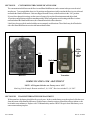
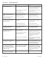
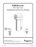
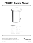
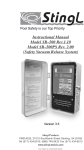
EZ100 EASYTOUCH OWNER’S MANUAL
4-Function Hand-Held Wireless Remote Control
IMPORTANT SAFETY INSTRUCTIONS
READ AND FOLLOW ALL INSTRUCTIONS
SAVE THESE INSTRUCTIONS
Table of Contents
SECTION I.
APPLICATION ............................................................................................................................................... 2
SECTION II.
KIT INCLUSION ............................................................................................................................................ 2
SECTION III.
RECEIVER ....................................................................................................................................................... 2
SECTION IV.
POWER CENTER ........................................................................................................................................... 3
SECTION V.
POWER ISOLATION CIRCUIT BOARD .................................................................................................... 3
SECTION VI.
CABLE SPLITTERS (OPTIONAL) .............................................................................................................. 3
SECTION VII.
HAND-HELD REMOTE ................................................................................................................................ 3
SECTION VIII. USING THE HAND-HELD REMOTE .......................................................................................................... 3
SECTION IX.
RECEIVER CIRCUIT BOARD ...................................................................................................................... 4
SECTION X.
AUTOMATIC COUNTDOWN CYCLE (OPTIONAL) ............................................................................... 5
SECTION XI.
CUSTOMIZING THE COMMUNICATION LINK ..................................................................................... 6
SECTION XII. TRANSMITTER BATTERY REPLACEMENT ........................................................................................... 6
SECTION XIII. TROUBLESHOOTING ................................................................................................................................... 7
WARNING
Before installing this product, read and follow all warning notices and instructions which are included. Failure to
follow safety warnings and instructions can result in severe injury, death, or property damage.
Call (800) 831-7133 for additional free copies of these instructions.
Important Notice
Attention Installer.
This manual contains important information about the installation, operation and safe use of this
product. This information should be given to the owner/operator of this equipment.
IMPORTANT
The Hand-held remote may be used with wet hands, but should never be submersed in water, as this could
damage the unit. If accidental submersion occurs, dry unit out by removing battery cover and removing battery.
Position unit so that water can drain out. Reassemble when completely dry.
Pentair Pool Products
1620 Hawkins Ave., Sanford, NC 27330 • (919) 774-4151
10951 West Los Angeles Ave., Moorpark, CA 93021 • (805) 523-2400
Rev. D 2-19-04
1
P/N 520041
SECTION I.
APPLICATION
Used in conjunction with Compool CP100 and EasyTouch Control Systems.
Provides switching of four remote control circuits from a wireless hand-held remote.
It is typically used for activating the spa circulation, and for operating three auxiliary pieces of equipment (such as
lights, jet pump, air blower, waterfall, etc.)
Each of the four functions on the hand-held remote has an “ON” and an “OFF” button.
SECTION II.
1-qty.
1-qty.
4-qty.
4-qty.
SECTION III.
KIT INCLUDES:
Hand-held Remote (P/N 520018)
Receiver (with 8 ft. flexible conduit with 2 –9½ ft. cables inside)
Plastic Anchors (for mounting Receiver to a flat surface)
Mounting screws (for mounting Receiver to a flat surface)
RECEIVER
The functional range of the wireless remote (from Hand-held Remote to Receiver) is approximately 150 ft.
line-of-sight.
The Receiver should be mounted at a convenient location (on a flat surface) a minimum of 5 ft. above ground level
to optimize the functional range of the Hand-held Remote.
CAUTION
The Receiver should be mounted a minimum of 8 to 10 feet away from any air blower, which may be part of the
equipment set. The Receiver will not operate properly if it is close to a blower which is operating.
In order to mount the Receiver, it will be necessary to remove the two retaining screws located on the underside of
the Receiver, and carefully slide the Receiver case up and off of its backplate. Temporarily position the backplate
against its mounting surface so that the Receiver is oriented in an upright position (with antenna pointing upwards,
and flexible conduit protruding from the bottom of the Receiver). The circuit board may need to be temporarily
removed. Carefully disconnect the modular connectors at the bottom of the circuit board and slide the board out of
the backplate. Use a pencil to mark the four mounting points. For mounting to stucco walls, drill 3/16 in. dia. holes.
Insert the four plastic anchors (provided). Reposition the backplate over the mounting points and secure with the
four mounting screws (provided). Carefully slide the circuit board back into the backplate and connect the modular
connectors with the silver cable connector attached to Socket #1 (SILVER) and the black cable connector
attached to Socket #2. Then slide the Receiver case back onto the backplate, and secure using the two retaining
screws.
P/N 520041
2
Rev. D 2-19-04
SECTION IV.
POWER CENTER
WARNING
RISK OF ELECTRICAL SHOCK OR ELECTROCUTION
If your Compool electrical panel includes circuit breakers (almond colored steel enclosure), it is also required that the
main power into the home be switched off at the main circuit breaker box.
Before starting the installation process, disconnect power by switching off all circuit breakers to all associated pool and
spa equipment. Failure to do so may lead to severe electrical shock, which can result in death or severe personal
injury.
Loosen the LOCK SCREW on handle of hinged faceplate in left-side of Power Center, and swing open to expose
the low-voltage wiring compartment. If the Power Center incorporates a circuit breaker subpanel, it will be
necessary to temporarily remove the breaker panel in order to access the low-voltage wiring compartment.
Insert the flexible conduit (attached to Receiver) into the low-voltage compartment by threading through the plastic
bushing on the underside of the Power Center enclosure.
SECTION V.
POWER ISOLATION CIRCUIT BOARD
Locate the two cables (one silver and one black) protruding from the flexible conduit. Each cable has a modular
connector attached. If the Control System incorporates an Indoor Remote, disconnect any cables going to
Socket #2 of the Power Center circuit board. Plug the short cable (BLACK) from the Power Isolation circuit board
into Socket #2. Plug the black cable from the RF receiver into the socket marked “EZ-WIRELESS” of the Power
Isolation circuit board. The Power Isolation PCB has an additional socket to accommodate the Indoor Remote
cable from Socket #2 marked “CP100”. If there is no Indoor Remote, the silver cable for the receiver may be
plugged directly into Socket #1 of the Power Center circuit board. If the Control System incorporates an Indoor
Remote, it will be necessary to use a Cable Splitter for Socket #1. See SECTION VI. CABLE SPLITTERS
(Optional).
SECTION VI.
CABLE SPLITTERS (Optional)
If the Control System incorporates an Indoor Remote, disconnect any existing Indoor Remote cables from Socket #1.
It will be necessary to use a Cable Splitter (P/N 6CONDDUAL) to connect to the Power Center circuit board.
Plug the short cable (attached to single-connector end of each Cable Splitter) into Socket #1. Plug the cable from
the Indoor Remote and the silver cable from the receiver into the Cable Splitter sockets.
SECTION VII. HAND-HELD REMOTE
The Hand-held Remote will control four circuits.
SPA button activates the Spa circuit (duplicates Spa Button on Optional Indoor Remote).
“A” button activates Auxiliary 1 circuit (duplicates Button 1 on Optional Indoor Remote).
“B” button activates Auxiliary 2 circuit (duplicates Button 2 on Optional Indoor Remote).
“C” button activates Auxiliary 3 circuit (duplicates Button 3 on Optional Indoor Remote).
Each of the four functions on the hand-held remote has an “ON” and an “OFF” button.
It is possible to incorporate a 30-minute or 90-minute countdown cycle for the Spa and/or Auxiliary 1 circuit
(useful if Aux1 is used for a jet pump or air blower). In this instance, whenever those circuits are turned on, they
will automatically shut down (at the end of the countdown cycle) without having to push the “OFF” button.
In order to incorporate the countdown feature, it is necessary to make adjustments to the circuit board located
inside the Receiver unit.
SECTION VIII. USING THE HAND-HELD REMOTE
To activate a circuit, press and hold the appropriate “ON” button for at least a full second. To deactivate, press
and hold the “OFF” button in the same manner.
Rev. D 2-19-04
3
P/N 520041
SECTION IX.
RECEIVER CIRCUIT BOARD
To access the circuit board inside the Receiver, remove the two retaining screws located on the underside of the
Receiver, and slide the Receiver case up and off of its backplate.
On the circuit board, you will discover the following:
1) A 4-position configuration switch (designated S2), which can be used to configure an automatic countdown
cycle for the Spa and/or Aux1 circuit.
2) A 10-position configuration switch (designated S1), which can be used to customize the communication link
between the Receiver and Hand-held Remote.
3) 2-qty. status lights (designated POWER and COMMAND), which are used for trouble-shooting:
POWER: Indicates that the Control System is supplying power to the Receiver unit.
COMMAND: Flashes whenever a button is pushed on the Hand-held Remote.
P/N 520041
4
Rev. D 2-19-04
SECTION X.
AUTOMATIC COUNTDOWN CYCLE (OPTIONAL)
There is a 4-position configuration switch (designated S2) located on the Receiver circuit board. This switch
can be used to set a countdown cycle (time-out feature) for the Spa and/or Aux1 circuit. Once this feature has
been enabled, the equipment will automatically turn off after the countdown cycle irrespective of how the circuit
was turned on (by Indoor Remote, Spa-side Remote or Hand-held Remote).
Use a paper clip or other blunt instrument to slide the appropriate switch at S2 to the “ON” or “OFF” position,
in accordance with the following pictorial:
Rev. D 2-19-04
5
P/N 520041
SECTION XI.
CUSTOMIZING THE COMMUNICATION LINK
The communication link between the Receiver and Hand-held Remote can be customized to prevent electrical
interference. To accomplish this, there is a 10-position configuration switch located on the Receiver circuit board
and inside the Hand-held Remote. Units are shipped from the factory with all switches in the “ON” position.
If you wish to change this setting, use the corner of a paper clip or other blunt instrument and adjust both
10-position configuration switches to matching settings. If the configuration switch setting at the Receiver does
not match that of the Hand-held Remote, the communication link will not function.
Labels have been provided, marked with the most commonly used functions. These labels may be affixed to the
side of the Hand-held Remote to assist with button identification.
Affix
Button
ID
Labels
Here
S1
Switch
Receiver
Transmitter
COMMUNICATION LINK ADJUSTMENT
NOTE: All Program Switches are Factory set to “ON”.
Matching Code Example: Remote switches 2, 4, 6 “ON”. Receiver switched 2, 4, 6 “ON”.
SECTION XII.
TRANSMITTER BATTERY REPLACEMENT
With normal use, the battery should last for several years. In the event the battery must be replaced, slide the cover
from the bottom of the Hand-held Remote. Slide the battery from the retainer clip and discard in accordance with
local and/or state ordinances. Replace with 3V lithium battery number CR2032 or equivalent. Slide battery cover
onto remote and snap in place.
P/N 520041
6
Rev. D 2-19-04
SECTION XII.
TROUBLESHOOTING
Symptom
Possible Cause
Solution
POWER LED does not light.
LX Control Center does not have power.
Insure power is being supplied and that
the LX Control Center operates correctly
without the Receiver installed.
Defective cable or connection to the
LX Control Center.
Verify the function of the board using
known good cable set.
Defective Receiver board.
Contact Factory or Service center.
COM LINK LED does not light or
blink.
Defective cable or connection to
the LX Control Center
Verify the function of the board
using known good cable set.
In normal operation LED will blink
at least every 2 seconds.
Defective Receiver board.
Contact factory or service center.
COMMAND LED does not light when
Transmitter button(s) is pressed
- unit fails to operate.
Address switches are incorrectly
configured.
Verify that the address switches on the
Transmitter and Receiver board are
correct and match.
Transmitter battery has failed.
Replace Transmitter battery.
Defective Transmitter or Receiver.
Contact Factory or Service center.
Unit functions, but some circuits
do not work, or operate the
incorrect circuit.
Circuit selection switches are
incorrectly set.
Verify settings of SW1 through
SW4 on the Receiver board.
Unit fails to operate, or fails to
dependably at range.
Undue electrical noise.
Relocate the Receiver away from operate
equipment such as blower motors.
Too many obstructions between the
Transmitter and Receiver.
Relocate the Receiver in a location that
provides fewer obstructions to the area
the user commonly operates the
Transmitter.
Receiver unit is too near the ground.
Relocate the Receiver to maximize the
distance between the Receiver antenna
and the ground.
Unit seems to turn on or off circuits
without the user / Transmitter.
A near by home is operating a similar
wireless unit.
Select a an alternate address code for
the Transmitter and Receiver, i.e. change
the switches on both boards to an
alternate, but matching setting.
Unit dependably turns equipment ON,
but once equipment is running it
does not dependably turn equipment
OFF, or range is greatly reduced when
equipment is running.
Undue electrical noise is being produced
by one or more pieces of equipment
in close proximity to the Receiver.
Relocate the Receiver away from
equipment such as blower motors OR
relocate the Receiver in a location that
provides fewer obstructions to the area
the user commonly operates the
Transmitter.
Unit operates, but has greatly reduced
range compared to prior function.
Transmitter battery is failing.
Replace Transmitter battery.
Rev. D 2-19-04
7
P/N 520041
SAVE THESE INSTRUCTIONS.
Pentair Pool Products
1620 Hawkins Ave., Sanford, NC 27330 • (919) 774-4151
10951 West Los Angeles Ave., Moorpark, CA 93021 • (805) 523-2400
P/N 520041
8
Rev. D 2-19-04