1
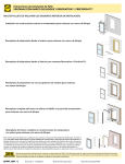
Vinyl Windows and Doors
V983492
Part Number: V983492
© 2010 Pella Corporation
INSTALLATION INSTRUCTION - INSTRUCCIONES DE INSTALACION
350 SERIES O,OX/XO SLIDINg PATIO DOOR
WITh fIXED PANEL INSTALLED
Lea las instrucciones en español en el reverso.
Table Of Contents
Installation Instruction Information ...........................................................................................Page-1
Exploded View of Installation and Parts List ............................................................................Page-2
Step 1: Rough Opening Preparation ........................................................................................Page-3
Step 3: Setting and Fastening the Door ..................................................................................Page-4
Step 2: Prepare the Door for Installation .................................................................................Page-4
Step 4: Reinstall the Sliding Panel ............................................................................................Page-7
Step 5: Integrating the Door to the Water Resistive Barrier .................................................Page-8
Step 6: Interior Seal ....................................................................................................................Page-8
Step 7: Sealing the Door to the Exterior Wall Cladding .......................................................Page-9
Step 8: Flush Flange Opening Preparation .......................................................................... Page-11
Step 9: Setting and Fastening the Door in Flush Flange Applications............................. Page-13
Step 10: Optional Sill Pan Fabrication and Installation ....................................................... Page-15
Cleaning Instructions and Important Notice Preparation ................................................... Page-16
Installation Instructions for Typical Wood frame Construction and Concrete Block
Constructions.
These instructions were developed and tested for use with typical wood frame wall and concrete
block constructions in a wall system designed to manage water. Installation details specific to
replacement of Aluminum Sliding Doors in Hard Coat Stucco applications can be found at the end
of this instruction. These instructions are not to be used with any other construction method.
Installation instructions for use with other construction methods or multiple units may be obtained
from Pella Corporation or local Pella retailer. Building designs, construction methods, building
materials, and site conditions unique to your project may require an installation method different
from these instructions and additional care. Determining the appropriate installation method is the
responsibility of you, your architect, or construction professional.
The performance of any building is dependent upon the design, installation, and
workmanship of the entire building system. Pella Corporation strongly recommends consulting
an experienced architect, contractor, or structural engineer prior to installation of Pella products.
The individual (building owner, architect, contractor, installer and/or consumer) responsible for the
project must take into account local conditions, building codes, inherent component limitations,
the effects of aging and weathering on building components, and other design issues relevant
to each project. The determination of the suitability of all building components for each project,
as well as the design and installation of flashing and sealing systems, are the responsibility of the
building owner, architect, contractor, installer and/or consumer
Handling and Storage: Provide full support under the framework while storing, moving and
installing the product. DO NOT lift the product by the head member only. Remove the plastic
shipping material prior to storing or installing the product. DO NOT store in direct sunlight. Allow
sufficient spacing between products for ventilation
Page-1
REMEMBER TO USE APPROPRIATE PERSONAL PROTECTIVE EQUIPMENT.
Nailing Fin
Corner
Flashing
Tape
Side
Flashing
Tape
Head
Top
Flashing
Tape
Corner
Flashing
Tape
Water
Resistive
Barrier
Sheathing
Framing
Wood Blocking
Side Flashing Tape
Sill
Sill Flashing Tape #1
Sill Flashing Tape #2
Head
Concrete
block
Wood Blocking
Sill
Sill Flashing Tape #1
Sill Flashing Tape #2
Always read the Vinyl Window and Door Limited Warranty before purchasing
or installing Vinyl Windows and Doors manufactured by Pella Corporation. By
installing this product, you are acknowledging that this Limited Warranty is part of the terms of the
sale. Failure to comply with all Pella installation and maintenance instructions may void your Pella
product warranty. See Limited Warranty for complete details at http://warranty.pella.com.
YOU WILL NEED TO SUPPLY:
TOOLS REQUIRED:
• Cedar/impervious shims/spacers (24 to 40)
• 2" galvanized roofing nails (Nail-fin only) (1/4 lb.)
•Tape measure
• 1/4" x 2" masonry screws for concrete application
• Closed cell foam backer rod/sealant backer (20 to 30 ft.)
• Pella® SmartFlash™ foil backed butyl window and
door flashing tape or equivalent
• High quality exterior grade polyurethane or
silicone sealant (2 to 3 tubes per door)
•Level
•Square
•Hammer
•Stapler
•Sealant gun
SEALANT
• Great Stuff™ Window and Door Insulating Foam Sealant by the
• Dow Chemical Company or equivalent low pressure polyurethane
window and door foam - DO NOT use high pressure or latex foams.
• Pella aluminum sill support or 2 x 4 wood blocking
• Pella sill pan or equivalent
•Scissors or utility knife
•Screwdrivers (#2 Phillips)
•3"-5" Wide putty knife
•Drill
• Interior trim and/or jamb extensions (20 to 30 ft.)
•#2 Phillips bit
Installation will require two or more
persons for safety reasons.
Page-2
•Square (Robertson)
drill bit
1
ROUGH OPENING PREPARATION
If replacing an Aluminum sliding door in hardcoat stucco, see Step 8 flush flange
Opening Preparation on page 11.
Interio
r
A. Confirm the opening is plumb and level. Ensure
the bottom of the rough opening does not slope
toward the interior.
Note: For peak water performance it is critical the
bottom be level within +/- 1/16".
1A
B. Confirm the door will fit the opening. Measure all
four sides of the opening to make sure it is 1/2" larger
than the door in width and height. Measure the width
at the top, bottom, and center. Measure the height at
the far left side, the far right side, and in the center.
Interio
r
Note: 1-1/2" or more of solid wood blocking is
required around the perimeter of the opening.
Fix any problems with the rough opening
before proceeding.
1B
C. Nail-fin only: Cut the water resistive barrier (1C).
Water Resistive Barrier
1st cut
3rd cut
1C
4th cut:
Make a 6" cut up from
each top corner at a 45°
angle to allow the water
resistive barrier to be
lapped over the fin at
the head of the door.
2nd
cut
Exterio
r
D. Nail-fin Only: Fold the water resistive barrier (1D). Fold
side flaps into the opening and staple to inside wall. Fold
top flap up and temporarily fasten with flashing tape.
E. Apply sill flashing tape #1. Cut a piece of flashing tape 12"
longer than the opening width. Apply at the bottom of the
opening as shown (1E) so it overhangs 1" to the exterior.
Note: The tape is cut 12" longer than the width of the
opening so that it will extend up each side approximately 6".
1D
1"
1E
6"
"
1/2/2"
F. Tab the sill flashing tape and fold. Cut 1" wide tabs at
each corner (1/2" from each side of corner) (1F). Fold tape
to the exterior and press firmly to adhere it to the water
resistive barrier.
Page-3
1
1F
1
ROUGH OPENING PREPARATION (CONTINUED)
1"
G. Apply sill flashing tape #2. Cut a piece of flashing tape
12" longer than the opening width. Apply at the bottom,
overlapping tape #1 by at least 1". DO NOT allow the tape to
extend past the interior face of the framing (1G).
1G
Note: The flashing tape does not need to extend all the way
to the interior of the framing.
If using optional sill pan, see Step 10 Sill Pan fabrication and Installation on page 15.
2
PREPARE THE DOOR FOR INSTALLATION
TWO OR MORE PEOPLE WILL BE REQUIRED TO hANDLE ThE PANEL SAfELY
A. Remove the packaging from the door. Inspect
the frame and panels for damage. DO NOT install
damaged units.
Note: If screens or hardware are removed from
the door at this time, label them and store them in
a protected area.
B. Locate the kitted parts bag. Remove from unit and
place in a safe location that is accessible during the
door installation.
C. Remove the vent panel. With the jamb side of the
door down, slide the panel all the way to one direction,
while lifting the panel out of the bottom frame pocket.
Swing the panel out of the frame.
2B
2
1
Interior View
D. Transom/Sidelight only: Remove the sill track and
pocket covers by pulling on the paper ring. DO NOT
damage these items as they will be re-installed once
the frame is fastened to the opening.
3
SETTING AND FASTENING THE DOOR
TWO OR MORE PEOPLE WILL BE REQUIRED TO hANDLE ThE PANEL SAfELY
If installing in a block replacement or a concrete floor, go to Step 3A to remove the bottom
fin. If NOT removing the bottom fin go to Step B.
A. To remove the bottom fin, lay the door down with the interior facing up. With a utility
knife, carefully score the entire length of the fin three times where it meets the sill. Bend the
fin back and forth a few times, then peel the fin off.
Note: Keep the body of the knife against the frame to prevent gouging the sill.
Page-4
3
SETTING AND FASTENING THE DOOR (CONTINUED)
B. Dry fit the door. Make sure the door is plumb, square
and level. Drill anchor locations with 1/8" masonry bit.
Mark the interior of the door frame at the sill to show a
boundary for sealant placement. Carefully remove and
set the door aside.
C. Apply two continuous 1/4" to 3/8" diameter beads
of sealant across the sill of the opening and 12" up the
jambs, towards the interior side of the door (between
the anchor holes and interior edge of door). DO
NOT apply sealant between the anchor holes and the
exterior side of the sill plate or floor.
Note: Failure to properly seal the sill attachment
screws and sill plate may allow water to penetrate
the interior of the home.
3C
12
"
r
o
ch
an le
ho
Interior View
D. Insert the door from the exterior of the building. Place the bottom of the door at the
bottom of the opening, then tilt the top into position. Center the door between the sides
to allow equal clearance for shimming. Make sure the door is plumb, level and square.
Door frames with Nail fin: Insert one 2" galvanized
roofing nail into the top of each jamb nailing fin.
Door frames without Nail fin: Insert one screw in the
top hole of each jamb.
Note: When installing doors without a bottom fin, DO
NOT slide the bottom of the door into the opening, as
sliding will damage the sealant lines. Insert sill anchor
screws prior to shimming.
Exterio
r
3D
Interio
r
E. Plumb and square the door. Insert shims at
the jambs between the door and the sides of
the rough opening. Place shims behind each of
the pre-drilled installation holes. DO NOT place
shims at the sill. DO NOT place shims at the
head until Step 4I.
Page-5
3E
3
SETTING AND FASTENING THE DOOR (CONTINUED)
F. fasten the door to the opening:
Door frames with Nail fin Only: Insert one 2" galvanized
roofing nail into every other pre-punched hole in the nailing fin.
All frame Types:
Transom/Sidelight: Remove the sill track and pocket covers
by pulling on the paper ring.
head and Jambs: At each pre-drilled installation hole, drill
1/8" pilot holes through the outer frame wall, shims and the
rough opening. Drive #10 x 2" corrosion resistant pan head
screws (wood rough openings) or 1/4" x 2" masonry screws
(masonry rough openings) into each pre-drilled hole.
JAMB
Sill: Place a dab of sealant in each pre-drilled hole in the sill
prior to installing the sill screws. Place a #10 rubber washer
on each sill screw. Drive the screw until the head contacts the
frame, however DO NOT sink the head.
Note: At the sill, it is imperative that sealant be applied
under the screw heads and that it surrounds them to
prevent water leakage. Failure to properly seal the sill
attachment screws may allow water to penetrate the
interior of the home.
Sidelights and Transoms Only: Replace the pocket covers
and sill track.
Fixed Side - Exterior Frame Pocket
EXTERIOR
G. Secure the fixed panel(s) by driving in the #10 x
1-1/2" fixed panel screws. Install the screws from
the interior at an angle as shown. Space one screw
16" from the top and one 16" from the bottom then
one screw in the center.
3G
INTERIOR
Interior
H. Install the panel track. Clean the pocket
of any debris and snap the track into the
interior panel pocket.
Exterior
3H
I. Install the panel bumpers. Locate the slit on the
bumper(s) and place it on the track. Press down to
seat the bumper onto the panel track cap.
3I
Page-6
3
SETTING AND FASTENING THE DOOR (CONTINUED)
2-PANEL (OX)
EXTERIOR
J. Install jamb pocket cover in pocket
above bumper.
Fixed
Panel
2-PANEL (XO)
EXTERIOR
POCKET
COVER
POCKET
COVER
INTERIOR
LOCK KEEPER
K. Install the lock keeper/strike. Position the keeper/
strike at the pre-drilled pilot holes. Insert a shim between
the frame jamb and rough opening at the keeper/strike
location. Fasten using (3) #10 x 3" screws (provided).
4
L
Vent
Panel
INTERIOR
REINSTALL THE SLIDING PANEL
TWO OR MORE PEOPLE WILL BE REQUIRED TO hANDLE ThE PANEL SAfELY.
A. Insert door panel. From the interior of the building, tilt
the top of the panel toward the door frame and insert the
top of the door panel into the top track. Move the bottom
of the panel toward the door frame until it is vertical.
Gently set the panel down into the bottom track.
5A
4A
Note: Make sure the top of the panel clears the antilift clip before attempting to place the panel on the
bottom track.
Note: A wide putty knife may be needed to raise the
rollers above the sill when installing the panel.
Slide panel
B. Adjust the rollers so that the slide panel runs freely
and is parallel to the fixed interlocker. Rotate the middle
roller screw clockwise to raise the panel or counterclockwise to lower the panel. They are located at the
bottom of the slide panel at both ends. Once plumb,
adjust the slide panel to the proper height to attain
even coverage of the weather strip at both the top and
bottom as viewed from the exterior.
C. Install the weep hoods in the weep slots on the
sill. Place the top of the weep hood against the sill
then swing the bottom into the latched position.
Sill
Interior View
1
4C
6C
Note: The screen track ends do not need weep
hoods. This is where the screen track weeps.
2
Page-7
5B
4B
Roller adjustment screw
5
INTEGRATING THE DOOR TO THE
WATER RESISTIVE BARRIER
A. Apply the side flashing tape. Cut two pieces of flashing
tape 4" longer than the frame height of the door. Apply
one piece to each side over the nailing fin and onto the
water resistive barrier. The tape should extend 2" above
the top of the door and 2" below the bottom of the door.
Press the tape down firmly.
Exterio
r
5A
Exterio
r
B. Apply the top flashing tape. Cut a
piece of flashing tape long enough to
go across the top of the door and
extend at least 1" past the side
flashing tape on both sides. Apply
5B
the tape over the top nailing fin as
shown. Press the tape down firmly.
5C
Exterio
r
1"
Note: The tape should cover the
entire nailing fin, but not extend
onto the door frame. The top flashing tape
must overlap the side flashing tape to prevent water
from getting behind it.
5D
C. fold down the top flap of the water resistive barrier.
D. Apply flashing tape to the diagonal cuts. Cut pieces of
flashing tape at least 1" longer than the diagonal cuts in the
water resistive barrier. Apply the tape, covering the entire
diagonal cut in the water resistive barrier at both upper
corners of the door. Press the tape down firmly.
Note: Be sure to overlap the top corners.
E. Attach the wood blocking or aluminum sill support to the
exterior of the opening to support the edge of the door sill.
6
5E
Solid wood blocking
the entire length of
the sill member
INTERIOR SEAL
Caution: Ensure use of low pressure polyurethane window and door insulating foams
and strictly follow the foam manufacturer’s recommendations for application. Use of
high pressure foams or improper application of the foam may cause the door frame to
bow and hinder operation.
A. Apply insulating foam sealant. From the interior, insert
the nozzle of the applicator approximately 1" deep into
the space between the door and the rough opening and
apply a 1" deep bead of foam. This will allow room for
expansion of the foam and will minimize squeeze out. If
using foam other than Great Stuff™ Window and Door
Insulating Foam Sealant by the Dow Chemical Company,
allow the foam to cure completely (usually 8 to 24 hours)
before proceeding to the next step.
Note: It may be necessary to squeeze the end of the
tube with pliers to be able to insert into the space
between the door frame and the rough opening. DO
NOT completely fill the space from the back of the fin
to the interior face of the door.
Page-8
Interio
r
6A
6
INTERIOR SEAL (CONTINUED)
B. On the interior, seal the door sill to the floor with a corner bead of sealant. Connect this
bead of sealant to the insulating foam at both door jambs.
C. Check the door operation by opening and closing the door.
Note: If the door does not operate correctly, check to make sure it is still plumb, level,
square and the sides are not bowed. If adjustments are required, remove the foam
with a serrated knife. Adjust the shims, and reapply the insulating foam sealant.
7
SEALING THE DOOR TO THE EXTERIOR
WALL CLADDING
NAIL-fIN fRAME:
Note: When applying siding, brick veneer or other exterior finish materials, leave
adequate space between the door frame and the material for sealant. Refer to the
illustration that corresponds to your finish material. Not allowing adequate space or
not using backer rod may cause the sealant to break down prematurely and allow
water to infiltrate.
VINYL/STEEL
SIDING
BRICK VENEER
Backer rod
and
sealant
typical
Backer rod
and
sealant
typical
Insulating
Foam
WOOD SIDING
WITH TRIM
Backer rod
and
sealant
typical
Insulating
Foam
Insulating
Foam
3/8"
3/8"
3/8"
1/2" Min.
1/2" Min.
1/2" Min.
REPLACEMENT fRAME:
Note: When applying siding, brick veneer or other exterior finish materials, leave
adequate space between the door frame and the material for sealant. Refer to the
illustration that corresponds to your finish material. Not allowing adequate space
or not using backer rod may cause the sealant to break down prematurely and allow
water to infiltrate.
BRICK VENEER
WOOD SIDING
WITH TRIM
Backer rod
and
sealant typical
Insulating
Foam
Insulating
Foam
3/8"
Backer rod
and
sealant typical
3/8"
3/8" Min.
3/8" Min.
Page-9
7
SEALING THE DOOR TO THE EXTERIOR
WALL CLADDING (CONTINUED)
NAIL-fIN fRAME AND REPLACEMENT fRAME:
A. Insert closed cell foam backer rod into the space
around the door approximately 1/2". This should
provide at least a 1/2" clearance between the backer
rod and the exterior face of the door.
7A
B. Apply a bead of high quality exterior grade
sealant to the entire perimeter of the door. On
doors where the bottom fin has been removed,
insert sealant into the spaces between the
bottom of the door and the sill support and
connect it to the perimeter sealant.
7B
Note: Refer to the sealant manufacturer’s
label to verify compatibility with vinyl and
the adjoining building components and
priming requirements.
C. Shape, tool and clean excess sealant. When
finished, the sealant should be the shape of an hourglass.
Note: This method creates a more flexible sealant line capable of
expanding and contracting.
fLUSh fLANgE fRAME:
D. Place a corner bead of sealant on the edge of the door flush flange on top and sides.
DO NOT seal the sill of the door frame to the opening.
Exterior View
7D
Corner bead
of sealant
JAMB CROSS SECTION
Page-10
8
FLUSH FLANGE OPENING PREPARATATION
Installation Instructions for Replacement of Aluminum Sliding Doors in
Hard Coat Stucco Applications.
These instructions are designed for typical California hard coat stucco exterior applications.
The installation must leave the existing aluminum sliding door frame and weep system in
place. These instructions are not to be used with any other construction method and
rely on the integrity of the existing aluminum sliding door frame and flashing system.
Building designs, construction methods, building materials, and site conditions unique
to your project may require an installation method different from these instructions and
additional care. Determining the appropriate installation method is the responsibility of
you, your architect, or construction professional. If you have questions, please contact your
local Pella retailer.
A. Prepare the door opening by removing the venting
panel and the glass from the existing fixed side of the
aluminum door frame.
Note: It may be necessary to cut the divider between
the venting panel and fixed glass areas with a
hacksaw. The existing aluminum frame is left in
place so as not to disturb the existing exterior stucco
flashing or drainage system.
8A
8B
B. Cut the existing door sill out of the opening. Using a
hacksaw or side grinder, cut the existing sill as close to
the longest leg of the jamb extrusion as possible.
8B
Note: Be careful to avoid damage to the interior
flooring materials. Drilling holes in the sill prior to
cutting may make the removal of the existing sill
easier. If existing sill has a stainless steel cap on
the sill, removing the cap prior to cutting will make
cutting easier.
C. Clean old sealant and other debris from the door
opening.
D. Remove the door lock strike from the lock jamb of
the existing door frame.
F. If the weep holes of the existing sill have
been cut away, drill new weep holes in the
existing door jambs. Be sure to drill weep holes
in all vertical jamb legs, except the most
interior leg.
8F
INTERIOR
E. Place a bead of sealant at each joint where the
existing door frame jambs meet the existing door
sill pieces. Fill any holes in the jamb and head
with sealant.
8B NOTE
8E
Note: Ensure that all new or existing weep holes
are open before proceeding with the installation.
G. Cut wood blocking to fill the vent and fixed
panel cavities in the head and jamb of the existing
door frame. The depth of the blocking should be
the same height as the tallest leg of the existing
jamb extrusion. Cut the head blocking to fill the
entire length of the head in both channels. Cut the
jamb blocking to fill both jamb channels to within
approximately 1” of the bottom of the jamb.
Page-11
8G
8
FLUSH FLANGE OPENING PREPARTATION
(CONTINUED)
H. Install the wood blocking in the head existing door frame. Place a 3/16" bead of
sealant in the door panel cavities, then insert the wood blocking into the head cavities.
Next insert the wood blocking into the jamb panel cavities of the existing door frame.
I. Construct a door sill pan for the door. Measure the distance between the cut ends of
the existing door sill and add 2". Measure 1" from each end and cut through the vertical
leg of the pan material. Bend bottom flaps of the pan material up, then bend the back
leg around the end of the pan.
CONSTRUCT A DOOR SILL PAN
1“
Cut
here
Fold
up
Fold
end
in tab
REPEAT STEPS FOR OPPOSITE END
TWO OR MORE PERSONS ARE REQUIRED fOR ThE fOLLOWINg STEPS.
J. Remove the packaging from the door. Inspect the frame and panels for damage.
DO NOT install damaged units.
Note: If screens or hardware are removed from the door at this time, label them
and store them in a protected area.
K. Remove the panel(s). With the jamb side of the
door down, slide each panel all the way to the right
or left, while lifting the panel out to the bottom frame
pocket, swing the panel out of the frame.
8K
2
Note: Door may have fixed panel fully installed. If
so, remove the vent panel only.
1
Interior View
L. Dry fit the sill pan and the door into the opening.
Note: If the new door frame is deeper than the existing door frame, it will be
necessary to cut the interior flooring material back to allow the door flush flanges to
contact the existing aluminum door frame.
M. from the exterior, set the door into the opening. Set the sill of the door on the sill pan
and tilt the door into position.
N. Insert shims around the door temporarily while you verify that the door will fit into the
opening and that the door flanges will overlap the stucco or existing aluminum door frame
by a minimum of 3/4" on all sides.
Note: Fix any problems with the opening before proceeding.
Page-12
8
FLUSH FLANGE OPENING PREPARTATION
(CONTINUED)
O. Using a pencil, mark the interior and exterior Sealant Placement, arrows indicate
edges of the sill pan on the sill of the rough
sealant locations.
opening. Remove the door and sill pan.
P. Place a 1/4" diameter bead of sealant in the
following locations:
- The exterior side of the interior
pencil mark.
8O
8P
- The interior side of the exterior
pencil mark.
- Midway be tween t he e xterior and in terior
sealant beads.
Q. Place a bead of sealant across the ends
of the three sealant beads, connecting the
three beads and sealing the exposed ends
of the existing aluminum sill. Also place a
bead of sealant on the vertical legs of the
existing sill.
8Q
8Q
R. Install the sill pan into the opening, aligning
the interior and exterior edges with the pencil
marks from Step O. Press down on the sill pan
to seal it into the opening.
S. Check all visible sealant lines for voids and
fill any voids with sealant.
8R
9
SETTING AND FASTENING THE DOOR IN
FLUSH FLANGE APPLICATIONS
A. Place one 1/4" diameter bead of sealant in
the following locations:
- In the bend at the back of the sill pan.
- 1/2" from the exterior edge of the sill pan.
- Midway between the interior and exterior
beads of sealant.
Also seal the joint between the back and side
legs of the sill pan with sealant.
9A
Page-13
9
SETTINg AND fASTENINg ThE DOOR IN fLUSh fLANgE
APPLICATIONS (CONTINUED)
B. Place a 1/4" diameter continuous bead of sealant on the face of the existing door
frame jambs and head.
C. from the exterior, set the door into the opening. Set the sill of the door onto the sill
pan and tilt the door into position, centering it in the opening. DO NOT slide the door on
the sill pan.
Exte
rior
Exte
rior
View
View
9B
9C
D. Insert shims between the door and the sides of the opening at the top two anchor hole
locations in the door.
Note: Keep the exterior of the door pressed against the existing door frame to
ensure a good sealant line.
E. At the top pre-drilled installation hole of each
jamb, drill a 1/8" pilot hole through the frame shims,
wood blocking and aluminum door frame.
1-1/4" minimum screw
embedment required
1/8" pilot hole
9E
#10 x 4" pan head
corrosion resistant scew
Shim
9F
F. Drive a #10 x 4" pan head corrosion
resistant screw through the opening
at the installation hole locations.
*Note: A minimum of 1-1/4" embedment into the
wood blocking is required. Adjust screw length
accordingly based on the existing conditions.
Page-14
9
SETTINg AND fASTENINg ThE DOOR IN fLUSh fLANgE
APPLICATIONS (CONTINUED)
G. Plumb and square the door. Insert shims
between the new door frame and the existing door
frame at the pre-drilled anchor hole locations in
the door jambs. DO NOT ShIM ThE hEAD UNTIL
ALL fIXED PANELS ARE INSTALLED. Move the
door in the opening until the flanges are tight
against the existing aluminum door frame.
Inter
ior V
iew
9G
Note: DO NOT over shim.
H. Drill a 1/8" pilot hole through the door frame,
shims, blocking and aluminum frame at each predrilled installation screw hole location.
I. Drive a #10 pan head corrosion resistant screw
into the rough opening at the installation hole locations.
DO NOT INSTALL fASTENERS IN hEAD UNTIL ALL fIXED PANELS
hAVE BEEN INSTALLED.
go to Step 4
10
OPTIONAL SILL PAN fABRICATION
AND INSTALLATION
Construct a door sill pan for the door. Measure the distance between the cut ends of the
existing door sill and add 2". Measure 1" from each end and cut through the vertical leg of
the pan material. Bend bottom flaps of the pan material up, then bend the back leg around
the end of the pan.
Dry fit the sill pan and the door into the opening.
CONSTRUCT A DOOR SILL PAN
1“
Cut
here
Fold
up
Fold
end
in tab
REPEAT STEPS FOR OPPOSITE END
from the exterior, set the door into the opening.
Set the sill of the door on the sill panel and tilt the
door into position.
Using a pencil, mark the interior and exterior
edges of the sill pan on the sill of the rough
opening. Remove the door and sill pan.
Place a 1/4” diameter bead of sealant in the
following locations:
- The exterior side of the interior pencil mark.
- The interior side of the exterior pencil mark.
- Midway between the exterior and interior
sealant beads.
Page-15
10
OPTIONAL SILL PAN fABRICATION
AND INSTALLATION (CONTINUED)
Install the sill pan into the opening, aligning the
interior and exterior edges with the pencil marks
from previous illustration. Press down on the sill pan
to seal it into the opening.
Place one 1/4” diameter bead of sealant in the
following locations:
Sealant between the
back and side legs
of sill pan
Leave gap at each
end of sealant lines
- In the bend at the back of the sill pan.
- 1/2” from the exterior edge of the sill pan.
- Midway between the interior and exterior beads
of sealant.
- Leave a 2” sealant gap at teach end of the two
exterior lines of sealant for drainage.
Also seal the joint between the back and side legs of the sill pan with sealant.
Return to Step 2
CLEANINg INSTRUCTIONS
Remove labels and clean the glass, using a soft, clean, grit-free cloth and mild soap or detergent.
Be sure to remove all liquid by wiping dry or use a clean squeegee. The vinyl frame may be
cleaned as described above. For stubborn dirt, a "non-abrasive" cleaner such as Bon-Ami® or Soft
Scrub® may be used. DO NOT use solvents such as mineral spirits, toluene, xylene, naphtha or
muriatic acid as they can dull the finish, soften the vinyl and/or cause failure of the insulated unit
seal. Keep door tracks clear of dirt and debris. Keep weep holes open and clear of obstructions.
IMPORTANT NOTICE
Because all construction must anticipate some water infiltration, it is important that the wall system
be designed and constructed to properly manage moisture. Pella Corporation is not responsible
for claims or damages caused by anticipated and unanticipated water infiltration; deficiencies in
building design, construction and maintenance; failure to install Pella® products in accordance
with Pella installation instructions; or the use of Pella products in wall systems which do not allow
for proper management of moisture within the wall systems. The determination of the suitability of
all building components, including the use of Pella products, as well as the design and installation
of flashing and sealing systems are the responsibility of the Buyer or User, the architect,
contractor, installer, or other construction professional and are not the responsibility of Pella.
Pella products should not be used in barrier wall systems which do not allow for proper
management of moisture within the wall systems, such as barrier Exterior Insulation and Finish
Systems, (EIFS) (also known as synthetic stucco) or other non-water managed systems. Except
in the states of California, New Mexico, Arizona, Nevada, Utah, and Colorado, Pella makes no
warranty of any kind and assumes no responsibility for Pella windows and doors installed
in barrier wall systems. In the states listed above, the installation of Pella products in barrier
wall or similar systems must be in accordance with Pella installation instructions.
Product modifications that are not approved by Pella Corporation will void the Limited Warranty.
V983492
Page-16