1
Vinyl Windows and Doors
Part Number: V981553
©2009 Pella Corporation
Manufactured by Pella Corporation
INSTALLATION INSTRUCTION - INSTRUCCIONES DE INSTALACION
FOR SLIDING PATIO DOOR
Lea las instrucciones en español en el reverso.
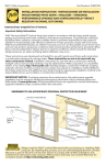
Installation Instructions for Typical Wood Frame Construction.
These instructions were developed and tested for use with typical wood frame wall construction in
a wall system designed to manage water. These instructions are not to be used with any other
construction method. Installation instructions for use with other construction methods or multiple
units may be obtained from Pella Corporation or local Pella retailer. Building designs, construction
methods, building materials, and site conditions unique to your project may require an installation
method different from these instructions and additional care. Determining the appropriate installation
method is the responsibility of you, your architect, or construction professional.
Handling and Storage: Provide full support under the framework while storing, moving and installing
the product. DO NOT lift the product by the head member only. Remove the plastic shipping material
prior to storing or installing the product. DO NOT store in direct sunlight. Allow sufficient spacing
between products for ventilation.
YOU WILL NEED TO SUPPLY:
TOOLS REQUIRED:
• Cedar or Impervious shims/spacers (12 to 20)
• 2" galvanized roofing nails (1/4 to 1/2 lb.)
• Closed cell foam backer rod/sealant backer (12 to 30 ft.)
• Pella® SmartFlash™ foil backed butyl window and
door flashing tape or equivalent
• High quality exterior grade polyurethane or
silicone sealant (2 to 3 tubes per door)
• Great Stuff ™ Window and Door Insulating Foam Sealant by the
Dow Chemical Company or equivalent low pressure polyurethane
window and door foam - DO NOT use high pressure or latex foams.
• Wood blocking for sill
• Optional stainless steel screws and anchors for installation on
concrete floor.
For High Performance Applications:
• #8 x 1-1/2" corrosion resistant Phillips pan head screws (75 to 100)
• #8 x 3/4" outside diameter corrosion resistant flat washers (75 to 100)
• Tape measure
SEALANT
• 2' or 4' Level
• Square
• Hammer
• Stapler
• Sealant gun
• Scissors or utility knife
• Screwdrivers (#2 Phillips with
8" shaft and small flat blade)
• Drill
Installation will require two or more persons for safety reasons.
REMEMBER TO USE APPROPRIATE
PERSONAL PROTECTIVE EQUIPMENT.
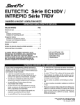
/BJMJOH'JO
$PSOFS
'MBTIJOH
5BQF
4JEF
'MBTIJOH
5BQF
)FBE
5PQ
'MBTIJOH
5BQF
$PSOFS
'MBTIJOH
5BQF
8BUFS
3FTJTUJWF
#BSSJFS
4IFBUIJOH
'SBNJOH
8PPE#MPDLJOH
4JEF'MBTIJOH5BQF
4JMM
4JMM'MBTIJOH5BQF
4JMM'MBTIJOH5BQF
Always read the Vinyl Window and Door Limited Warranty before purchasing
or installing Vinyl Windows and Doors manufactured by Pella Corporation. By
installing this product, you are acknowledging that this Limited Warranty is part of the terms of the
sale. Failure to comply with all Pella installation and maintenance instructions may void your Pella
product warranty. See Limited Warranty for complete details at http://warranty.pella.com.
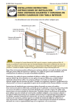
1 ROUGH OPENING PREPARATION
A. Verify the opening is plumb and level. Ensure the
bottom of the rough opening does not slope toward
the interior.
*OUFSJP
S
Note: It is critical that the bottom is level.
£
B. Verify the door will fit the opening. Measure all four
sides of the opening to make sure it is 1/2" larger than
the door in width and height. Measure the width at the
top, bottom, and center. Measure the height at the far
left side, the far right side, and in the center.
Note: 1-1/2" or more of solid wood blocking is
required around the perimeter of the opening. Fix any
problems with the rough opening before proceeding.
*OUFSJP
S
£
C. Cut the water resistive barrier (1C).
8BUFS3FTJTUJWF#BSSJFS
TUDVU
SEDVU
£
OE
DVU
UIDVU
.BLFBDVUVQGSPN
FBDIUPQDPSOFSBUB¡
BOHMFUPBMMPXUIFXBUFS
SFTJTUJWFCBSSJFSUPCF
MBQQFEPWFSUIFmOBUUIF
IFBEPGUIFEPPS
&YUFSJP
S
£
D. Fold the water resistive barrier (1D). Fold side flaps into
the opening and staple to inside wall. Fold top flap up and
temporarily fasten with flashing tape.
E. Apply sill flashing tape #1. Cut a piece of flashing tape 12"
longer than the opening width. Apply at the bottom of the
opening as shown (1E) so it overhangs 1" to the exterior.
Note: The tape is cut 12" longer than the width of the opening
so that it will extend up each side approximately 6".
£
F. Tab the sill flashing tape and fold. Cut 1" wide tabs at each
corner (1/2" from each side of corner) (1F). Fold tape to the
exterior and press firmly to adhere it to the water resistive barrier.
G. Apply sill flashing tape #2. Cut a piece of flashing tape 12" longer
than the opening width. Apply at the bottom, overlapping tape #1
by at least 1". DO NOT allow the tape to extend past the interior
face of the framing (1G).
Note: The flashing tape does not need to extend all the way to
the interior of the framing.
£
£
2 PREPARE THE DOOR FOR INSTALLATION
TWO OR MORE PEOPLE WILL BE REQUIRED TO HANDLE THE PANEL SAFELY.
Interio
r View
A. Remove the packaging from the door. Inspect the frame and
sash for damage. DO NOT install damaged units.
Note: If screens or hardware are removed from the door at
this time, label them and store them in a protected area.
2B
B. Relocate the slide panel bumper. Remove the bumper located at
the top of the fixed jamb, and install in the fixed jamb against the
sill track.
*OUFSJP
S7JFX
C. Remove the venting panel. Slide the panel to the open position,
making sure it clears the anti-lift clip. Lift the panel out of the
lower track and tilt the bottom of the panel away from the door
frame. Then, lower the panel out of the top track. Carefully set
the panel aside in a safe place.
Ó
£
REVERSING DOOR SLIDE: If changing the slide of the door
panel, refer to Installation Instructions (Reversing Door Slide)
later in this booklet. Note: Doors with Blinds-Between-the-Glass
are not reversible.
Î
Ó
3 SETTING AND FASTENING THE DOOR
TWO OR MORE PEOPLE WILL BE REQUIRED FOR THE FOLLOWING STEPS.
IF INSTALLING ON A CONCRETE FLOOR, refer to Installation Instructions
(Bottom Fin Removal) later in this booklet.
A. Insert the door from the exterior of the building. Place
the bottom of the door at the bottom of the opening, then
tilt the top into position. Center the door between the sides
of the opening to allow equal clearance for shimming,
and insert one roofing nail in the first hole from the
corner on each end of the top nailing fin. These are
used to hold the door in place while shimming it
plumb and square.
Î
Note: When installing doors without a bottom
fin, DO NOT slide the bottom of the door into the
opening, as sliding will damage the sealant lines. Insert
sill anchor screws prior to shimming.
&YUFSJP
S
Î
*OUFSJP
S
B. Plumb and square door. Insert shims between the door and
the sides of the rough opening starting up 6" from the bottom
of the door. Also shim between the top of the door and the
rough opening above the fixed interlocker and at the mid-point
between the fixed interlocker and the lock jamb.
Note: DO NOT over shim.
Î
C. Fasten the door to opening:
&YUFSJP
S
Note: Pre-drilling the additional holes in the fin at the interlocker
will make installation easier and will help prevent damage to the
fin. Use a 3/16" drill bit to pre-drill the holes.
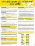
Standard Installation: Beginning in the first hole from the
fin corner, drive 2" galvanized roofing nails into every other
pre-punched hole in the nailing fin. Drive four additional
nails through the head and sill fin at the fixed interlock
location. Space the nails 2" on center and position them so
there are two nails on each side of the interlocker. Drive the
nails until the head contacts the fin, however do not sink the
head. This will allow for movement of building material.
Î
High Performance Installation: Beginning in the first hole
from the fin corner, insert a #8 x 1-1/2" corrosion resistant
screw with a 3/4" outside diameter flat washer into every hole
of the installation fin. Drive four additional screws through
the head and sill fin at the fixed interlock location. Space the
screws 2" on center and position them so there are two screws
on each side of the interlocker. Drive the screws until the
head/washer contacts the fin, however do not sink the washer.
This will allow for movement of building material.
2" 2" 2" 2"
Performance
3C High
Screw Placement
4 INTEGRATING THE DOOR TO THE WATER RESISTIVE BARRIER
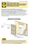
A. Apply side flashing tape. Cut two pieces of flashing tape 4"
longer than the frame height of the door. Apply one piece to
each side over the nailing fin and onto the water resistive barrier.
The tape should extend 2" above the top of the door and 2"
below the bottom of the door. Press the tape down firmly.
{
B. Apply top flashing tape. Cut a piece of flashing tape long
enough to go across the top of the door and extend at least
1" past the side flashing tape on
both sides. Apply the tape over the
&YUFSJP
S
top nailing fin as shown. Press the
tape down firmly.
Note: The tape should cover the
entire nailing fin, but not
extend onto the door frame.
The top flashing tape must
overlap the side flashing tape
to prevent water from getting
behind it.
&YUFSJP
S
{
&YUFSJP
S
{
{
C. Fold down top flap of water resistive barrier (4C).
D. Apply flashing tape to diagonal cuts. Cut pieces of flashing tape at
least 1" longer than the diagonal cuts in the water resistive barrier.
Apply the tape, covering the entire diagonal cut in the water resistive
barrier at both upper corners of the door. Press the tape down firmly.
Note: Be sure to overlap the top corners (4D).
E. Attach wood blocking to the exterior of the opening to support the
edge of the door sill.
{
4PMJEXPPECMPDLJOH
UIFFOUJSFMFOHUIPG
UIFTJMMNFNCFS
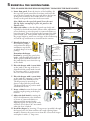
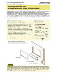
5 REINSTALL THE SLIDING PANEL
TWO OR MORE PEOPLE WILL BE REQUIRED TO HANDLE THE PANEL SAFELY.
A. Insert door panel. From the interior of the building, tilt
the top of the panel toward the door frame and insert the
top of the door panel into the top track. Move the bottom
of the panel toward the door frame until it is vertical.
Gently set the panel down into the bottom track.
x
Note: Make sure the top of the panel clears the antilift clip before attempting to place the panel on the
bottom track.
B. Adjust the rollers so that the slide panel runs freely and
is parallel to the fixed interlocker. Rotate roller adjustment
screws clockwise to raise the panel or counter-clockwise to
lower the panel. They are located at the bottom of the slide
panel at both ends. Once plumb, adjust the slide panel to
the proper height to attain even coverage of the weatherstrip
at both the top and bottom as viewed from the exterior.
4MJEFQBOFM
x
3PMMFSBEKVTUNFOUTDSFX
4JMM
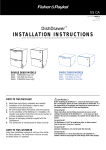
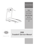
C. Identify the keeper in
the hardware package
and perform the keeper
attachment steps based
on which keeper is in the
package.
Determine the keeper
location by opening the panel a few
inches, and extending the lock hook.
With a pencil, mark the location on
the jamb directly across from the top
of the shank.
*OUFSJPS7JFX
Interior handle
Lock
adjustment
screw
Lock hook
Shank
Mortise lock
Handle latch
#6 x 1/2"
Starter
screw
5D
D. Place the keeper with 4 screw holes
on the jamb so the top of the slot is
aligned with the pencil mark. Attach
by inserting a #6 x ½” starter screw
into one of the slotted keeper holes.
E. Place the keeper with 2 screw holes
on the jamb by “snapping” it into the
frame jamb at the desired location.
The keeper may be moved up or
down to align with the pencil mark.
The keeper will stay in position until
attached with screws.
F. Insert a shim between the frame jamb
and the rough opening at the keeper
location.
5C
5E
Keeper
Keeper
5F
Shim
5F
Loosen
G. Adjust the lock hook by turning the
door lock adjustment screw clockwise
5G Tighten
to loosen or counter-clockwise to
tighten until the mortise lock is
aligned properly, the door locks easily,
and there is less than 1/16" movement
when the door is locked.
H. Install the keeper by inserting 3" long screws (provided) through
the keeper holes, the shim and into the rough opening frame
members. Remove the starter screw from the 4 screw hole keeper
and replace it with a 3" long screw.
5H
5H
Shim
I. Install screen by inserting the top of the screen into the screen pocket located at the exterior
head of the patio door. Compress the top rollers just enough to allow the bottom of the
screen to be inserted onto the bottom screen track. Adjust the screen rollers by turning the
adjustment screw located at the top and bottom until the screen operates smoothly and is
plumb and centered from top to bottom. Install the screen keeper if desired.
6 INTERIOR SEAL
Caution: Ensure use of low pressure polyurethane window and door insulating foams
and strictly follow the foam manufacturer's recommendations for application. Use of
high pressure foams or improper application of the foam may cause the door frame to
bow and hinder operation.
A. Apply insulating foam sealant. From the interior, insert
the nozzle of the applicator approximately 1" deep into the
space between the door and the rough opening and apply a
1" deep bead of foam. This will allow room for expansion
of the foam and will minimize squeeze out. If using foam
other than Great Stuff ™ Window and Door Insulating
Foam Sealant by the Dow Chemical Company, allow the
foam to cure completely (usually 8 to 24 hours) before
proceeding to the next step.
Note: It may be necessary to squeeze the end of the tube
with pliers to be able to insert into the space between the
door frame and the rough opening. DO NOT completely
fill the space from the back of the fin to the interior face
of the door.
*OUFSJP
S
È
B. On the interior, seal the door sill to the floor with a corner bead of sealant.
Connect this bead of sealant to the insulating foam at both door jambs.
C. Check door operation by opening and closing the door.
Note: If the door does not operate correctly, check to make sure it is still plumb, level,
square and that the sides are not bowed. If adjustments are required, remove the foam
with a serrated knife. Adjust the shims, and reapply the insulating foam sealant.
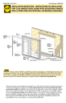
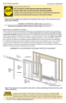
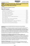
7 SEALING THE DOOR TO THE EXTERIOR WALL CLADDING
Note: When applying siding, brick veneer or other exterior finish materials, leave adequate
space between the door frame and the material for sealant. Refer to the illustration that
corresponds to your finish material. Not allowing adequate space or not using backer rod
may cause the sealant to break down prematurely and allow water to infiltrate.
VINYL/STEEL
SIDING
BRICK VENEER
Backer rod
and
sealant
typical
Backer rod
and
sealant
typical
Insulating
Foam
WOOD SIDING
WITH TRIM
Insulating
Foam
Insulating
Foam
1/2"
1/2"
1/2"
1/2" Min.
Backer rod
and
sealant
typical
1/2" Min.
1/2" Min.
A. Insert closed cell foam backer rod into the space around the
door approximately 1/2". This should provide at least a 1/2"
clearance between the backer rod and the exterior face of
the door.
Note: Backer rod adds shape and depth for the
sealant line.
B. Apply a bead of high quality exterior grade sealant
to the entire perimeter of the door. On doors where the
bottom fin has been removed, insert sealant into the spaces
between the bottom of the door and the sill support and
connect it to the perimeter sealant.
Ç
Note: Refer to the sealant manufacturer's label to verify
compatibility with vinyl and the adjoining building
components and priming requirements.
Ç
C. Seal the exterior drainage weeps at the head only
with high quality exterior grade sealant. DO NOT
seal the drainage weeps at the sill.
D. Shape, tool and clean excess sealant. When finished,
the sealant should be the shape of an hourglass.
Note: This method creates a more flexible sealant line
capable of expanding and contracting.
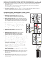
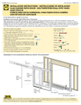
INSTALLATION INSTRUCTIONS (BOTTOM FIN REMOVAL)
A. To remove the bottom fin, lay the door down with the interior facing up. With a utility knife,
carefully score the entire length of the fin three times where it meets the sill. Bend the fin back
and forth a few times, then peel the fin off.
Note: Keep the body of the knife against the frame to prevent gouging the sill.
B. Remove the sill track by beginning at one end and carefully pulling it up. This will expose the
slide panel pocket.
Note: A hooked tool like an allen wrench will easily get the track started.
C. Drill 3/16" holes through the sill 18" from each corner and 13/16" from the interior of the door. Continue every 18" thereafter.
Follow up by counter drilling the holes with a 3/8" drill making
sure to only penetrate the interior wall of the door frame.
Note: You will need a drill guide set at 1/4" from the end of
the drill bit. Without a drill guide, it is extremely difficult to
prevent drilling through both walls of vinyl with the 3/8" drill.
Penetrating the lower wall with this drill will make it very
difficult to seal against water penetration and difficult to secure.
D. Dry fit the door. Make sure that the door is plumb, square and
level. Mark and drill anchor locations. Mark the interior of the
door frame at the sill to show a boundary for sealant placement.
Carefully remove and set the door aside. Install anchors.
E. Apply 2 continuous 1/4" to 3/8" diameter beads of sealant
across the sill of the opening and 12" up the jambs, towards the
interior side of the door (between the anchor holes and interior
edge of door). DO NOT apply sealant between the anchor holes
and the exterior side of the sill plate or floor.
Note: Failure to properly seal the sill attachment screws and sill
plate may allow water to penetrate the interior of the home.
EF TMJ OFMU
QBDLF
QP
M
SJM
E
M
SJM
E
*OUFSJPS7JFX
S
P
DI
BO MF
IP
*OUFSJPS7JFX
INSTALLATION INSTRUCTIONS (BOTTOM FIN REMOVAL) (continued)
F. Go to steps 3 and 4 to install the door frame into the opening. Then install the sill track before
proceeding to step 5.
Note: At the sill, it is imperative that sealant be applied under the screw heads and that it
surrounds them to prevent water leakage.
G. To snap the sill track in, place an 8" long 2" x 4" block on edge and begin tapping it from one
end with a rubber mallet until the track snaps into its original position.
INSTRUCTIONS (REVERSING DOOR SLIDE)
Backplate
Note: Doors with Blinds-Between-the-Glass are not reversible.
Lock hook
A. Remove the sill and screen tracks from the door.
(Use an allen wrench or small hook to begin removal.)
B. Rotate the main frame 180° (so the sill becomes the head).
Snap the sill and screen tracks into place at the bottom of the
door. Carefully lay the panel on saw horses or a clean surface.
Latch
lever
C
D
C. Extend the lock hook and clamp the lock hook with
the vise grip.
Note: Use of the vise grip on the lock hook will
prevent the mortise lock from falling when the lock
mounting screws are removed.
£
Ó
Î
.PSUJTF
MPDL
D. Remove the door handle by removing the two
attachment screws.
E. Remove the mortise lock. Remove the two screws
that attach the lock assembly to the door panel.
Work the lock down, then tilt it out and pull up.
F. Rotate 180° and reinstall the lock. Insert the mortise lock into
the door panel with the lock adjusting screw positioned at the
bottom, then tilt the top in and lift the lock into position. Insert
the two mounting screws into the lock mounting holes.
G. Rotate the handle 180° and install the door handle by
inserting the two backplate screws through the door panel
and into the exterior handle.
Note: Rotating the handle will result in "Pella" script
being upside down. A new handle must be ordered for
"Pella" to be in correct orientation.
Note: The latch lever must engage the slot in the side of the
mortise lock assembly.
H. Remove the bottom rollers from the slide panel by removing
the upper screw. Reinstall the rollers in the opposite end of
the door panel.
I. High Performance Doors only: Remove the blocks from the
top rail of the door panel and reinstall them at the opposite
end of the panel.
-PDL
BEKVTUJOH
TDSFX
.PVOUJOH
TDSFXT
4MJEF
QBOFM
CLEANING INSTRUCTIONS
Remove labels and clean the glass, using a soft, clean, grit-free cloth and mild soap or detergent. Be
sure to remove all liquid by wiping dry or use a clean squeegee. The vinyl frame may be cleaned as
described above. For stubborn dirt, a “non-abrasive" cleaner such as Bon-Ami® or Soft Scrub® may be
used. Do not use solvents such as mineral spirits, toluene, xylene, naphtha or muriatic acid as they can
dull the finish, soften the vinyl and/or cause failure of the insulated unit seal. Keep door tracks clear of
dirt and debris. Keep weep holes open and clear of obstructions.
IMPORTANT NOTICE
Because all construction must anticipate some water infiltration, it is important that the wall system
be designed and constructed to properly manage moisture. Pella Corporation is not responsible for
claims or damages caused by anticipated and unanticipated water infiltration; deficiencies in building
design, construction and maintenance; failure to install Pella products in accordance with Pella's
installation instructions; or the use of Pella products in wall systems which do not allow for proper
management of moisture within the wall systems. The determination of the suitability of all building
components, including the use of Pella products, as well as the design and installation of allow for
proper management of moisture within the wall systems. The determination of the suitability of
all building components, including the use of Pella products, as well as the design and installation
of flashing and sealing systems are the responsibility of the Buyer or User, the architect, contractor,
installer, or other construction professional and are not the responsibility of Pella.
Pella products should not be used in barrier wall systems which do not allow for proper management
of moisture within the wall systems, such as barrier Exterior Insulation and Finish Systems, (EIFS)
(also known as synthetic stucco) or other non-water managed systems. Except in the states of
California, New Mexico, Arizona, Nevada, Utah, and Colorado, Pella makes no warranty of any
kind on and assumes no responsibility for Pella windows and doors installed in barrier wall
systems. In the states listed above, the installation of Pella Products in barrier wall or similar
systems must be in accordance with Pella's installation instructions.
Product modifications that are not approved by Pella Corporation will void the Limited Warranty.