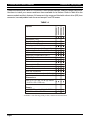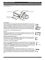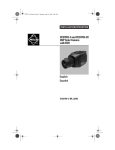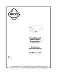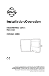
1
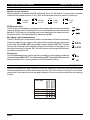
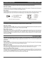
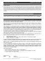
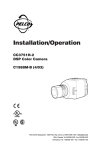
CC3320/CC4620 Series Color Cameras Installation/ Operation Manual C1932M (8/99) Pelco • 300 W. Pontiac Way, Clovis • CA 93612-5699 USA • Pelco Online @ http://www.pelco.com In North America and Canada: Tel (800) 289-9100 or FAX (800) 289-9150 • DataFAX (800) 289-9108 International Customers: Tel (1-559) 292-1981 or FAX (1-559) 348-1120 • DataFAX (1-559) 292-0435 CC3320 and CC4620 Cameras Installation Instructions INTRODUCTION These instructions cover Pelcos CC3320 and CC4620 Series cameras. Read all of these instructions. Use them to install your camera and have them available for its lifetime. Refer to Table A for the camera models and their features. All cameras in the range are fitted with a direct drive (DD) lens connector, have adjustable back focus and accept C and CS lenses. Color Resolution (TVL) Sensitivity (lux @ f1.2) CCD Sensor size Sony HyperHAD CCD Adjustable Gamma (0.45 and 1.0) Automatic Gain Control (AGC) AGC on/off Backlight Compensation (BLC) BLC on/off Manual Shutters Flickerless Electronic Iris (EI) EI on/off 4 White Balance modes* Auto Iris connection Line lock with phase adjust (AC only) CC3320-2X CC3320-3 CC4620-3 Option CC4620-2X TABLE A 480 480 330 330 1.0 1.0 0.9 0.9 1/3“ 1/3“ 1/3“ 1/3“ Dimensions 4.82 (L) x 2.57 (W) x 2.34 (H) inches (12.25 x 6.55 x 5.95 cm) Supply 11 - 40 VDC or 14 - 30 VAC, 50/60Hz 230 VAC + 10% -15% 50Hz * 4 Modes = Auto Tracing (ATW), Indoor, Outdoor and Fluorescent Page 2 Installation Instructions CC3320 and CC4620 Cameras PRODUCT SAFETY Ensure installation and servicing is carried out by qualified personnel. Isolate from the supply circuit before any servicing. Installation method and materials must be capable of supporting four times the total weight of the unit. Power supply cords must be connected as defined in national electrical codes of practice for Class 1 earth protected equipment. Low voltage cameras must be connected as defined in national electrical codes of practice for Class 2 protection of double or reinforced insulation. Safety critical components must only be replaced with recommended parts. The maximum load on the rear (auto-iris) connector must not exceed 50 mA. The maximum load on the direct drive connector must not exceed 25 mA. REGULATORY NOTICES Federal Communications Commission Part 15 - Digital devices This Device complies with part 15 of the FCC rules. Operation is subject to the following two conditions: (1) this device may not cause harmful interference, and (2) this device must accept any interference that may cause undesired operation. CERTIFICATIONS This product meets the requirements of the following standards: Electromagnetic Compatibility EN55022: 1995 limits and methods of measurement of radio disturbance characteristics of information technology EN50082-1: 1992 Generic immunity standard Comprising: IEC 1000-4-2:1995 Electrostatic discharge IEC 1000-4-3:1995 Radiated electromagnetic fields IEC 1000-4-6: Immunity to conducted disturbances, induced by radio-frequency fields IEC 1000-4-4:1995 Fast transient bursts Safety EN 60950: 1992 Safety of information technology equipment, including electrical business equipment DECLARATIONS The manufacturer declares that the equipment supplied with this manual is compliant with the EMC directive 89/336 EEC and the low voltage directive 73/23 EEC and CE marked accordingly. Page 3 CC3320 and CC4620 Cameras Installation Instructions CAUTIONS CAUTION In order to avoid damaging your camera, note the following points. 1) The camera has threaded mounting points on the top and bottom of the case. Only use a standard, photographic mounting bolt with a 1/4-20 UNC thread. 2) Before fitting the lens, make sure that its back will not touch the CCD sensor or associated components when fully installed. 3) Do not touch the image surface of the sensor. If the sensor is accidentally touched, only clean it using isopropanol. 4) Do not expose the sensor to direct sunlight as this may impair the performance of the camera. POWER SUPPLY The CC3320 and CC4620 Series cameras are available in 230 VAC or 11-40 VDC/14-30 VAC low voltage types. The voltage required to operate the camera is clearly marked on the rear panel of the camera. The green POWER LED on the rear panel indicates that power is connected. Power the low voltage cameras only from a class 2 isolated power supply. The power consumption is less than 5 Watts. 230 VAC Power Supply Cameras that are intended to operate directly from 230 VAC are fitted with a non-detachable power supply cord. The voltage of operation is clearly marked on the rear panel of the camera. Generally this is 230 VAC +10%/ -15% at 50 Hz. Refer to the wiring instruction label attached to the supply cord and terminate the cord with the appropriate circuit with a 3A fuse. CAMERAS MUST BE CONNECTED TO A PROTECTIVE EARTH GROUND. Ensure that a secure means of isolation from the AC power is provided for the camera in accordance with the national wiring regulations of the country of installation. Auto-switching power supply Cameras fitted with an automatic selecting power supply operate between 11-40 VDC and 14-30 VAC. Connections and polarity are indicated above the screw terminals on the rear panel. The power supply must be a class 2 isolated type. VIDEO CONNECTIONS To obtain a video output, connect a video coaxial cable terminated with a 75W BNC connector to the BNC socket marked VIDEO OUT on the rear of the camera. Page 4 Installation Instructions CC3320 and CC4620 Cameras FUNCTION SWITCHES On the side of the camera is a hinged flap. The hinged flap covers a lens level potentiometer and 10 function switches. Mounting boss Back focus adjustment Function switches DD lens level adjustment DD lens connector Color Balance There are four color balance modes selected by DIP switches 1 and 2. For the majority of applications the Auto setting will provide excellent color rendition and is the default setting. For applications where the illumination is predominantly daylight, the Outdoor setting may provide improved color rendition over Auto. Where a mixture of illuminations such as tungsten, fluorescent and daylight exist, the Indoor setting may provide the best color rendition. Where fluorescent lighting is predominant, use the Fluorescent setting. Gamma There are two different levels of Gamma selected by DIP switch 3. Choose between Normal (0.45) to provide increased visibility in dark areas of the scene, or Linear (1.0). The default setting is Normal. AGC (Automatic Gain Control) The Automatic Gain Control feature can improve picture quality when levels of illumination are low. Select ON or OFF using DIP switch 4. For most applications, the AGC should be ON and is the default setting. LL-PH (Line Lock, Phase Adjust) The Line Lock, Phase Adjust feature is selected by DIP switches 5 and 6. Choose Fixed or Adjustable. Both settings are line-locked; however, the Adjustable setting allows ±120O phase adjustment via the potentiometer located on the rear of the camera. The Adjustable mode should be used when cameras are connected to different AC power supply phases. Default setting is Fixed. 5 6 Fixed 5 6 Adjustable SYNC (Synchronization) The Synchronization feature is selected using DIP switch 6. Choose LL (LineLock) or Internal. LL locks the frame rate to the power supply frequency so that cameras are triggered at the same point on the power supply AC cycle. Internal locks the frame rate to the internal oscillator of the camera. The default setting is LL. Page 5 CC3320 and CC4620 Cameras Installation Instructions FUNCTION SWITCHES Shutter speed switches Shutter speeds are selected with DIP switches 8, 9 and 10. DIP switch 7 must be down to enable manual shutter speed selection. For EI, BLC and Flickerless functions, switch 7 must be up. 7 8 9 10 7 8 9 10 7 8 9 10 7 8 9 10 1/10,000 1/2,000 1/500 1/125 1/4,000 1/1,000 1/250 1/50 EI (Electronic Iris) The EI (Electronic Iris) feature compensates for excessive light level by automatically adjusting shutter speed. Selecting Electronic Iris disables manual shutter speed selection. The Electronic Iris setting must not be used when the camera is set to Flickerless mode. The default setting is Electronic Iris ON. BLC (Back Light Compensation) The BLC (Back Light Compensation) feature compensates for back-lit scenes by enhancing objects in the center of the scene which would previously have been in silhouette. Select ON or OFF using the BLC switch. Default is OFF. BLC will only function with a manual iris lens when the Electronic Iris feature is switched on. For direct drive and auto iris lenses, BLC will still function even though the Electronic Iris feature is switched off. Flickerless The Flickerless setting can reduce the flicker caused by certain lighting conditions. Choose between ON or OFF. The default setting is OFF. Note that the Electronic Iris setting must be off for correct operation of the Flickerless function. LENS SELECTION 1/3" 1/2" 2/3" 1" Page 6 CC3320-2X CC3320-3 CC4620-3 Lens size CC4620-2X Suitable lens types are C and CS mount in fixed iris, manual iris, auto-iris or direct drive versions. Sizes are shown below. Cameras are factory set for CS mount lenses. If using a C mount lens, rotate either of the back focus screws approximately 30 turns counterclockwise before installing the lens. Installation Instructions CC3320 and CC4620 Cameras LENS CONNECTION Fixed and manual iris lenses (for indoor use only) require no wiring connections. Auto-Iris Lenses Connections for auto-iris lenses are located on the rear of the camera. Connect auto-iris lenses to the 3-terminal connector according to the diagram below. Direct Drive Connect DD lenses to the female 4-pin socket on the side of the camera. If the lens does not have a DD plug fitted, then wire the lens to a suitable plug in accordance with the diagram below. + V + = Lens positive supply = Lens ground V = Video drive signal Auto-Iris Lens Connections 1 2 3 4 1 = Damp 2 = Damp + 3 = Drive + 4 = Drive - DD Lens Connector LENS SETUP PROCEDURES For manual or fixed iris lenses set the EI switch and AGC switch to ON. Auto-Iris Lenses Switch the EI and AGC OFF. Refer to the lens instructions and adjust the lens for the optimum picture (video output level of 1V peak-to-peak). Switch the AGC ON. Direct Drive Lenses Where fitted, switch the EI and AGC OFF. Use an appropriate screwdriver to turn the lens level potentiometer (under the hinged flap) fully clockwise. Next, slowly adjust the potentiometer counterclockwise until the optimum picture is obtained (video output level of 1V peak-to-peak). Switch the AGC ON. FOCUS ADJUSTMENT The back focus adjustment screws are located on the top and side of the case at the front of the camera and should be adjusted using an appropriate screwdriver. Do not over turn the back focus mechanism. Fixed Lenses Set the lens focus to infinity and view an image greater than 6.5 feet (2 m) away. Focus the image using the back focus screw. Set the lens focus as required. Manual Iris Lenses Open the iris fully and set the lens focus to infinity. View an image greater than 6.5 feet (2 m) away. Focus the image using the back focus screw. Set the lens focus and iris as required. Auto-iris and Direct Drive Lenses Fully open the iris by covering the lens with a suitable neutral density (ND) filter. Set the lens focus to infinity. View an image greater than 6.5 feet (2 m) away. Focus the image using the back focus screw. Remove the ND filter and set the lens focus as required. Page 7 CC3320 and CC4620 Cameras Installation Instructions FOCUS ADJUSTMENT Zoom Lenses Set the lens focus to infinity and fully open the iris by covering the lens with a suitable neutral density (ND) filter. Zoom out to the widest field of vision and view a distant object. Adjust the back focus screw until the object is in focus. Next, zoom fully in and adjust the lens focus until the object is again focused. Repeat these steps until the full zoom range may be viewed with the minimum loss of focus. SYNCHRONIZATION Cameras that operate from AC power supplies are line-locked for a supply frequency of 50 Hz. If the supply frequency is unstable, then disable the line lock by setting the SYNC switch to Internal. WARRANTY AND RETURN INFORMATION Pelco will repair or replace, without charge, any camera proved defective in material or workmanship for a period of two years after the date of shipment. Pelco will warrant all replacement parts and repairs for 90 days from the date of Pelco shipment. Repairs made necessary by reason of misuse, alteration, normal wear, or accident are not covered under this warranty. Pelco assumes no risk and shall be subject to no liability for damages or loss resulting from the specific use or application made of the Products. Pelcos liability for any claim, whether based on breach of contract, negligence, infringement of any rights of any party or product liability, relating to the Products shall not exceed the price paid by the Dealer to Pelco for such Products. In no event will Pelco be liable for any special, incidental or consequential damages (including loss of use, loss of profit and claims of third parties) however caused, whether by the negligence of Pelco or otherwise. The above warranty provides the Dealer with specific legal rights. The Dealer may also have additional rights, which are subject to variation from state to state. If a warranty repair is required, the Dealer must contact Pelco at (800) 289-9100 or (559) 292-1981 to obtain a Repair Authorization number (RA), and provide the following information: 1. 2. 3. Model and serial number Date of shipment, P.O. number, Sales Order number, or Pelco invoice number Details of the defect or problem If there is a dispute regarding the warranty of a product which does not fall under the warranty conditions stated above, please include a written explanation with the product when returned. Method of return on warranty shipments shall be the same or equal to the method by which the item was received by Pelco. In order to expedite parts returned to the factory for repair or credit, please call the factory at (800) 2899100 or (559) 292-1981 to obtain an authorization number (CA number if returned for credit, and RA number if returned for repair). Goods returned should be clearly identified with the assigned CA/RA number and freight should be prepaid. All merchandise returned for credit may be subject to a 20% restocking and refurbishing charge. Ship freight prepaid to: Pelco, 300 West Pontiac Way, Clovis, CA 93612-5699, or Pelco c/o American Overseas Airfreight , 320 Beach Road, Burlingame, CA 94101 (if shipped outside the United States) REVISION HISTORY Manual # Date C1932M 8/99 8/99 Comments Original version AC supply voltage changed from 12-30 VAC to 14-30 VAC Page ® Pelco8and the Pelco logo are registered trademarks of Pelco © Copyright 1999, Pelco. All rights reserved. Pelco Manual C1932M (8/99)