1
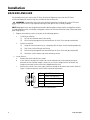
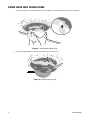
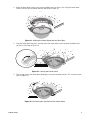
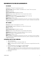
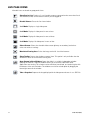
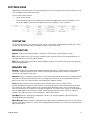
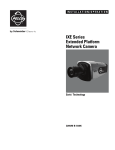
Q U I C K
S T A R T
ID and IDE Series
Network Fixed
Dome Cameras
Sarix™ Technology
C2961M (10/09)
Product Overview
Figure 1. Camera Connections and Features
2
C2961M (10/09)
ì Relay and Alarm Connections: One relay that can be used to control an external circuit, and one
alarm for physical input into the system.
î Accessory Port: For use with compatible Pelco accessories.
ï RJ-45 Network Port: Connects the camera to the IP network. Also supplies power to the camera
through the network using Power over Ethernet (PoE). If PoE is not available, the camera is
prewired for 24 VAC.
ñ 24 VAC Power Connections: Supports 24 VAC as the power source if PoE is not used.
ó Reset Button: Reboots the camera or restores the camera’s factory default settings. This button is
recessed. Using a small tool, such as a paper clip, press and release the reset button once to reboot
the camera. Press and hold the reset button for 10 seconds to restore the camera to the factory
default settings.
r Micro SD Card Slot: Saves a snapshot image to a micro SD card based on alarm activity.
s Power LED: Glows solid amber and then glows solid green during and after the configuration
sequence. The LED can be disabled through the user interface. If this LED glows red (solid or
flashing), contact Pelco Product Support at 1-800-289-9100 (USA and Canada) or +1-559-292-1981
(international) for assistance.
t Lens Mount: Fits a standard CS-mount lens. Use a megapixel lens with the ID Series and
IDE Series megapixel cameras. A standard definition lens installed on a megapixel camera will
limit the resolution of the camera and create poor image quality.
u Auto Iris Lens Connector: Controls the auto iris lens. Insert the 4-pin connector from the DC drive
auto iris lens into this connector.
~í NTSC/PAL Button: Toggles the service port between NTSC and PAL formats. The default setting is
NTSC.
~â Service Port: Outputs analog video. Use this port at the installation site to set up the field of view
and to focus the camera. When a service cable is connected to the camera, video to the IP stream
is disabled.
~ä Auto Back Focus Button: Sets the auto back focus mechanism. Press once to center the auto
back focus mechanism and to fully open the iris. Press and hold the button for three seconds to
start the auto back focus mechanism and focus the camera.
~ã Ethernet Activity/Link LED: Flashes green to indicate that data is being transmitted or received
by the camera. Glows solid amber to indicate that a live network connection is established.
NOTES:
•
Pelco recommends connecting the camera to a network that uses a Dynamic Host Configuration
Protocol (DHCP) server to address devices.
•
Do not use a hub in the network setup of the camera.
•
To secure access to the IP camera, place the camera behind a firewall when it is connected to a
network.
C2961M (10/09)
3
Installation
BACK BOX AND LENS
For detailed instructions, refer to the ID Series Installation/Operation manual or the IDE Series
Installation/Operation manual. Both are available on the resource disc.
WARNING: Remove the foam insert from the back box before installing the system. The foam
insert secures the tilt ring to prevent damage to the optical chassis during shipment.
NOTE: Megapixel lenses are designed and tested to deliver optimal image quality to megapixel cameras.
A standard definition lens installed on a megapixel camera will limit the resolution of the camera and create
poor image quality.
1. Prepare the mounting surface using one of the following options:
•
•
In-Ceiling Installation
(1)
Cut a 6-inch diameter hole in the ceiling.
(2)
Pull all wiring through the hole and terminate all wires (if not already terminated).
Surface Installation
(1)
Using the surface mount ring as a template, drill the holes for the mounting hardware.
(2)
Drill a hole in the ceiling for the wiring.
(3)
Pull all wiring through the hole and terminate all wires (if not already terminated).
(4)
Attach the surface mount ring to the mounting surface.
2. Install the lens:
a.
Remove the cover from the lens mount.
b.
Screw the lens onto the lens mount. Be careful to prevent dust from entering the space
between the lens and the imager. If necessary, use clean, compressed air to remove any
foreign matter (refer to the instructions shipped with the lens).
c.
Connect the auto iris lens to the 4-pin connector located on the side of the camera. Refer to
Figure 2 for pin connections and iris drive connector information.
3
1
4
2
Pin
DC (AID) Auto Iris Lens
1
Control coil negative (–)
2
Control coil positive (+)
3
Drive coil positive (+)
4
Drive coil negative (–)
Figure 2. Lens Pin Connections
4
C2961M (10/09)
3. Plug the network cable into the RJ-45 network port on the side of the back box. If the network has
no PoE, connect a 24 VAC Class 2 power supply to the 24 VAC power connector.
1
Pin
8
87
TX+
8
2
TX–
1
3
RX+
4
PoE 1-2
5
PoE 1-2
65
43
21
1 2 3 4 5
6 7 8
1
2
3
4
6
7
8
6
RX–
7
PoE 3-4
8
PoE 3-4
8
5
Function
1
7
6
5
4
3
2
1
Figure 3. RJ-45 Pin Descriptions
4. Connect the necessary wiring for alarms and relays (refer to Figure 4). Only use the 24 VAC wires if
PoE is not available.
RELAY
R1
A1
ALARM
24V~
RELAY
R1
ALARM
A1
Figure 4. Alarm and Relay Wiring
24V~
Figure 5. 24 VAC Wiring
C2961M (10/09)
5
5. Install the back box using one of the following options:
•
In-Ceiling Installation
(1)
Install the back box by compressing the spring clips and pushing the back box through
the hole (refer to Figure 6).
(2)
Tighten the machine screws completely to secure the back box to the ceiling.
Figure 6. In-Ceiling Installation
•
Surface Installation
(1)
Install the back box in the surface mount ring by compressing the spring clips and
pushing the back box through the hole (refer to Figure 7).
(2)
Tighten the machine screws completely to secure the back box to the ceiling.
Figure 7. Surface Installation
6. Apply power to the camera. The camera will complete a configuration sequence: the green LED
flashes five times per second for approximately two minutes and then turns solid after the sequence
is complete.
NOTE: If the camera is not connected to a DHCP server and DHCP is enabled, the configuration
sequence might take up to five minutes to complete.
6
C2961M (10/09)
7. Position the camera
a.
View the camera image using the service port or a Web browser.
b.
Unlock the tab locks located on each side of the camera.
c.
Manually rotate and tilt the camera module to position the camera. Do not over-rotate the
module.
d.
Lock the tab locks to secure the camera.
ì Pan 368°
î Tab lock
ï Rotate 355°
ñ Tilt 160°
Figure 8. Positioning the Camera
8. Focus the lens:
a.
View the camera image using the service port or a Web browser.
b.
Press the auto back focus button, located on the rim of the back box, once to center the focus
mechanism.
c.
Manually adjust the zoom and focus of the lens to the desired field of view (refer to the
instructions shipped with the lens).
d.
Press and hold the back focus button for three seconds to start the auto back focus
mechanism.
C2961M (10/09)
7
DOME LINER AND LOWER DOME
1. Align the magnets on the dome liner with the magnets located on the back box (refer to Figure 9).
Figure 9. Installing the Dome Liner
2. Attach the lower dome leash to the back box (refer to Figure 10).
Figure 10. Attaching the Leash
8
C2961M (10/09)
3. Move the lower dome latches away from the bubble until you hear a click. Align the lower dome
latches with the slots located on the back box (refer to Figure 11).
Figure 11. Aligning the Lower Dome with the Back Box
4. Snap the lower dome into place, and then move the lower dome latches towards the bubble until
you hear a click (refer to Figure 12).
Figure 12. Locking the Lower Dome
5. Turn the top cover of the lower dome 90-degrees to conceal the dome latches, LED, and service port
(refer to Figure 13).
Figure 13. Positioning the Top Cover of the Lower Dome
C2961M (10/09)
9
Operation
Once the camera is installed, apply power to the camera. The camera will start a configuration sequence:
the green LED flashes five times per second for approximately two minutes, and then turns solid after the
boot cycle is complete and the camera is on line.
IP ADDRESS SETTINGS
If the camera is connected to a Dynamic Host Configuration Protocol (DHCP) network and DHCP is set to
the On position, the server will automatically assign an IP address to the device; DHCP On is the default
setting for the camera. Set DHCP to the Off position to manually set the camera’s IP address.
NOTES:
•
If the camera is not connected to a DHCP server but DHCP is set to On, the default IP address
192.168.0.20 on subnet mask 255.255.255.0 is automatically assigned to the camera. After the first
camera is connected and assigned the default IP address, the system will automatically look for other
cameras on the auto IP address system and assign IP addresses in sequential order as required.
For example if three cameras are connected to a network without a DHCP server, the first camera will
be assigned address 192.168.0.20, the second camera address 192.168.0.21, and the third camera
address 192.168.0.22.
•
•
10
Contact your network administrator to avoid network conflicts before setting or changing the
camera’s IP address.
If you do not know the camera’s IP address, install the Pelco Device Utility software available on the
resource disc shipped with the product. The utility will locate the assigned name, IP address, and
MAC address for devices connected to the same virtual local area network (VLAN) as your computer.
The Device Utility software is also available at www.pelco.com/software/downloads/.
C2961M (10/09)
MINIMUM SYSTEM REQUIREMENTS
ID SERIES
Processor: Intel® Pentium® 4 microprocessor, 1.6 GHz
Operating System: Microsoft® Windows® XP, Windows Vista®, or Mac® OS X 10.4 (or later)
Memory: 512 MB RAM
Network Interface Card: 100 megabits (or greater)
Monitor: Minimum of 1024 x 768 resolution, 16- or 32-bit pixel color resolution
Web Browser: Internet Explorer® 7.0 (or later) or Mozilla® Firefox® 3.0 (or later)
NOTE: Internet Explorer is not supported by Mac OS X 10.4.
Media Player: QuickTime® 7.55
NOTE: This product is not compatible with QuickTime version 7.6.4. If you have this version installed on
your system, uninstall it and then install QuickTime version 7.5.5, which is available on the resource disc
shipped with the product.
IDE SERIES
Processor: Intel Core™ 2 Duo microprocessor, 2.6 GHz
Operating System: Windows XP, Windows Vista, or Mac OS X 10.4 (or later)
Memory: 2 GB RAM
Network Interface Card: 100 megabits (or greater)
Monitor: Minimum of 1024 x 768 resolution, 16- or 32-bit pixel color resolution
Web Browser: Internet Explorer® 7.0 (or later) or Mozilla® Firefox® 3.0 (or later)
NOTE: Internet Explorer is not supported by Mac OS X 10.4.
Media Player: QuickTime® 7.55
NOTE: This product is not compatible with QuickTime version 7.6.4. If you have this version installed on
your system, uninstall it and then install QuickTime version 7.5.5, which is available on the resource disc
shipped with the product.
LOGGING ON TO THE CAMERA
1. Open the Web browser.
2. Type the camera’s IP address in the browser address bar.
NOTE: If you do not know the camera’s IP address, you can locate it using the Pelco Device Utility
software.
3. Click the Login button in the navigation bar; a dialog box appears.
4. Type your user ID and password; admin is the default for both.
NOTE: If you are logging on to the camera as the administrator for the first time, the default User ID
and Password are admin (all lowercase). For security purposes, be sure to change the password after
you log on for the first time.
5. Click Log In.
C2961M (10/09)
11
LIVE PAGE ICONS
Viewable icons are based on group permissions.
Show Device List: Displays a list of viewable cameras connected to the same virtual local
area network (VLAN) as the camera to which you are logged on.
Disable Viewer: Closes the live view window.
1 x 1 Mode: Displays a single video pane.
2 x 2 Mode: Displays 4 video panes in rows of two.
3 x 3 Mode: Displays 9 video panes in rows of three.
4 x 4 Mode: Displays 16 video panes in rows of four.
Select Stream: Selects the viewable video stream (primary or secondary) and selects
unicast or multicast settings.
Maximize Viewing Area: Scales the image to the full size of the browser.
Show Toolbar: Returns the window to normal view. This option is only available after the
window has been set to maximize viewing area.
Open Stream in New Window: Opens the video in a scalable, independent window.
Opening the video in a separate window allows you to view the video while other
applications are running. This window can be minimized, maximized, or closed using the title
bar buttons of the active window. The window can also be resized option by dragging the
lower-right corner of the window.
Take a Snapshot: Captures the image displayed in the video pane and saves it as a JPEG file.
12
C2961M (10/09)
SETTINGS PAGE
Depending on user permissions, the Settings page allows you to manage camera system settings, set up
users and groups, and control the camera.
To access the camera settings:
1. Log on to the camera.
2. Click the Settings link in the navigation bar located in the upper-right corner of the page; a list of
menu tabs appear. Place the mouse pointer over a tab to display a list of submenus.
Figure 14. Settings Page Menus
SYSTEM TAB
The System tab displays the firmware version, device name, enables and disables the power LED, allows
setup of the day and time settings, and permits event system email setup.
NETWORK TAB
General: Displays the hardware address, hostname, DHCP settings, and IP address settings.
SSL: Secure Socket Layers (SSL) encrypts communications making it difficult for unauthorized users to
intercept and view user names and passwords.
SSH: Secure Shell (SSH) allows Pelco Product Support to log on to and service the camera for advanced
troubleshooting purposes.
IMAGING TAB
General: Includes camera orientation and digital processing settings. The orientation settings allow for
standard or inverted installation of the camera. The digital processing settings adjust the sharpness,
saturation, and contrast of the scene.
Exposure: Adjusts scene detail and contrast. A scene with correct exposure settings has adequate detail
and contrast between white and dark values. An image with too little or too much exposure eliminates
detail in the scene. The camera features auto and manual exposure settings.
Focus: Includes auto back focus and manual focus settings (refer to Focus in the ID Series
Installation/Operation manual or the IDE Series Installation/Operation manual for detailed instructions).
The camera will focus when changes in the scene are detected. Manual focus turns off the auto focus
mechanism and locks the camera at a user-specified position. The manual focus setting is recommended
only for indoor applications that have a single, unchanging primary light source. The Focus page also
includes Full Range Auto-Focus, Quick Auto-Focus, and Factory Defaults.
Tone Map: Balances the brightest and darkest sections of an image to produce a picture with more
balanced lighting and more detail.
White Balance: Defines how the camera processes video images to render true colors in a scene. White
balance is especially effective in scenes with changing lighting conditions or in scenes with more than one
type of light source.
C2961M (10/09)
13
A/V STREAMS TAB
Use the A/V Streams tab to configure the video and audio streams for the camera. The A/V Streams tab
includes a Video Presets page, a Video Configuration page, and an Audio Configuration page.
Video Presets: The Video Preset page includes three fully-configured video presets, which include
primary and secondary video stream settings for easy setup. These presets may also be used as a starting
point for a custom video configuration. These preset configurations vary depending on camera model.
Video Configuration: The Video Configuration page allows you to customize the compression, resolution,
image rate, and bit rate of the video streams. The default names for the streams are Primary Stream and
Secondary Stream. Although each stream can be configured independently, the settings of one stream can
limit the options available to the other stream, depending on the processing power used.
NOTE: Always configure the primary stream before the secondary stream. The primary stream should
always be the most resource-intensive of the streams.
Audio Configuration: The Audio Configuration page allows you to setup the internal audio device or an
external audio device. The default setting for Audio is disabled, which means that no audio is transmitted
from the camera. When enabled, audio is transmitted from the camera to the PC. Based on your system
configuration, images and audio may not be synchronized.
NOTES:
•
Improper use of audio/visual recording equipment may subject you to civil and criminal penalties.
Applicable laws regarding the use of such capabilities vary between jurisdictions and may require,
among other things, express written consent from the recorded subjects. You are solely responsible
for insuring strict compliance with such laws and for strict adherence to any/all rights of privacy and
personalty.
•
Not all camera models are equipped with an internal audio device. Refer to the specifications for your
camera model for information.
USERS AND GROUPS TAB
Users: Defines the permissions assigned to individuals logged on to the camera. Use this feature to
create, modify, or delete user accounts.
NOTE: The only defined user that cannot be deleted is admin; however, the administrator password can
be changed. For security purposes, it is important that you change your password after you log on to the
device for the first time.
Groups: Defines the permissions assigned to users within a group. Use this setting to create, modify, and
delete groups and permissions. Multiple permissions can be assigned to each group.
General Settings: Changes the way the camera manages the users and groups settings. These settings
can be managed on a camera-to-camera basis or by using a centralized server to apply changes to multiple
cameras.
EVENTS TAB
Sources: Defines the camera functions that are automatically triggered by an event source. The camera
supports alarm, system, and timer event sources.
Handlers: Defines the actions that a camera takes when an event occurs. The camera supports four event
handlers: Send Email, Write JPEG to SD Card, Upload JPEG to FTP Server, and Open/Close Relay.
14
C2961M (10/09)
PRODUCT WARRANTY AND RETURN INFORMATION
WARRANTY
Pelco will repair or replace, without charge, any merchandise proved defective in material or workmanship for a period of one year after the date of
shipment.
Exceptions to this warranty are as noted below:
• Five years:
– Fiber optic products
– TW3000 Series unshielded twisted pair (UTP) transmission products
– CC3701H-2, CC3701H-2X, CC3751H-2, CC3651H-2X, MC3651H-2, and MC3651H-2X camera models
• Three years:
– Pelco-designed fixed network cameras and network dome cameras with Sarix™ technology.
– Pelco-branded fixed camera models (CCC1390H Series, C10DN Series, C10CH Series, and IP3701H Series)
– EH1500 Series enclosures
– Spectra® IV products (including Spectra IV IP)
– Camclosure® Series (IS, ICS, IP) integrated camera systems
– DX Series digital video recorders, DVR5100 Series digital video recorders, Digital Sentry® Series hardware products, DVX Series digital video
recorders, and NVR300 Series network video recorders
– Endura® Series distributed network-based video products
– Genex® Series products (multiplexers, server, and keyboard)
– PMCL200/300/400 Series LCD monitors
• Two years:
– Standard varifocal, fixed focal, and motorized zoom lenses.
– DF5/DF8 Series fixed dome products
– Legacy® Series integrated positioning systems
– Spectra III™, Spectra Mini, Spectra Mini IP, Esprit®, ExSite®, and PS20 scanners, including when used in continuous motion applications.
– Esprit Ti and TI2500 Series thermal imaging products
– Esprit and WW5700 Series window wiper (excluding wiper blades).
– CM6700/CM6800/CM9700 Series matrix
– Digital Light Processing (DLP®) displays (except lamp and color wheel). The lamp and color wheel will be covered for a period of 90 days.
The air filter is not covered under warranty.
– Intelli-M® eIDC controllers
– PMCL542F, PMCL547F, and PMCL552F FHD monitors
• One year:
– Video cassette recorders (VCRs), except video heads. Video heads will be covered for a period of six months.
• Six months:
– All pan and tilts, scanners, or preset lenses used in continuous motion applications (preset scan, tour, and auto scan modes).
Pelco will warrant all replacement parts and repairs for 90 days from the date of Pelco shipment. All goods requiring warranty repair shall be sent
freight prepaid to a Pelco designated location. Repairs made necessary by reason of misuse, alteration, normal wear, or accident are not covered under
this warranty.
Pelco assumes no risk and shall be subject to no liability for damages or loss resulting from the specific use or application made of the Products. Pelco’s
liability for any claim, whether based on breach of contract, negligence, infringement of any rights of any party or product liability, relating to the Products
shall not exceed the price paid by the Dealer to Pelco for such Products. In no event will Pelco be liable for any special, incidental, or consequential
damages (including loss of use, loss of profit, and claims of third parties) however caused, whether by the negligence of Pelco or otherwise.
The above warranty provides the Dealer with specific legal rights. The Dealer may also have additional rights, which are subject to variation from state
to state.
If a warranty repair is required, the Dealer must contact Pelco at (800) 289-9100 or (559) 292-1981 to obtain a Repair Authorization number (RA), and
provide the following information:
1. Model and serial number
2. Date of shipment, P.O. number, sales order number, or Pelco invoice number
3. Details of the defect or problem
If there is a dispute regarding the warranty of a product that does not fall under the warranty conditions stated above, please include a written
explanation with the product when returned.
Method of return shipment shall be the same or equal to the method by which the item was received by Pelco.
RETURNS
To expedite parts returned for repair or credit, please call Pelco at (800) 289-9100 or (559) 292-1981 to obtain an authorization number (CA number if
returned for credit, and RA number if returned for repair) and designated return location.
All merchandise returned for credit may be subject to a 20 percent restocking and refurbishing charge.
Goods returned for repair or credit should be clearly identified with the assigned CA or RA number and freight should be prepaid
10-1-09
REVISION HISTORY
Manual #
C2961M
Date
10/09
Comments
Original version.
Pelco, the Pelco logo, Camclosure, Digital Sentry, Endura, Esprit, ExSite, Genex, Intelli-M, Legacy, and Spectra are registered trademarks of Pelco, Inc.
Spectra III is a trademark of Pelco, Inc.
DLP is a registered trademark of Texas Instruments Incorporated.
All product names and services identified throughout this document are trademarks or registered trademarks of their respective companies.
The absence of a trademark or registered trademark from this document does not constitute a waiver of intellectual property rights.
© Copyright 2009, Pelco, Inc. All rights reserved.
www.pelco.com
Pelco, Inc. Worldwide Headquarters 3500 Pelco Way Clovis, California 93612 USA
USA & Canada Tel (800) 289-9100 Fax (800) 289-9150
International Tel +1 (559) 292-1981 Fax +1 (559) 348-1120