1
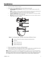
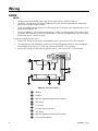
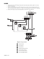
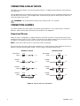
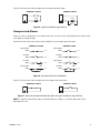
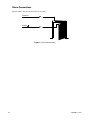
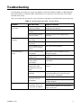
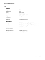
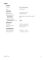
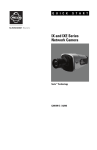
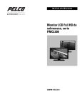
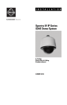
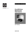
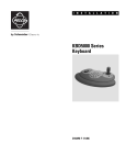
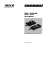
I N S T A L L A T I O N
AUD-1 Audio and
ALM-1 Alarm
Accessories
External Audio and Alarm Accessories
C2985M-A (3/11)
Contents
Important Notices. . . . . . . . . . . . . . . . . . . . . . . . . . . . . . . . . . . . . . . . . . . . . . . . . . . . . . . . . . . . . . . . . . . . . . 3
Regulatory Notices. . . . . . . . . . . . . . . . . . . . . . . . . . . . . . . . . . . . . . . . . . . . . . . . . . . . . . . . . . . . . . . . 3
Legal Notice . . . . . . . . . . . . . . . . . . . . . . . . . . . . . . . . . . . . . . . . . . . . . . . . . . . . . . . . . . . . . . . . . . . . . 3
Description . . . . . . . . . . . . . . . . . . . . . . . . . . . . . . . . . . . . . . . . . . . . . . . . . . . . . . . . . . . . . . . . . . . . . . . . . . .
Models . . . . . . . . . . . . . . . . . . . . . . . . . . . . . . . . . . . . . . . . . . . . . . . . . . . . . . . . . . . . . . . . . . . . . . . . .
Parts List. . . . . . . . . . . . . . . . . . . . . . . . . . . . . . . . . . . . . . . . . . . . . . . . . . . . . . . . . . . . . . . . . . . . . . . .
User-Supplied Parts List . . . . . . . . . . . . . . . . . . . . . . . . . . . . . . . . . . . . . . . . . . . . . . . . . . . . . . . . . . . .
4
4
4
4
Installation . . . . . . . . . . . . . . . . . . . . . . . . . . . . . . . . . . . . . . . . . . . . . . . . . . . . . . . . . . . . . . . . . . . . . . . . . . . 5
Wiring . . . . . . . . . . . . . . . . . . . . . . . . . . . . . . . . . . . . . . . . . . . . . . . . . . . . . . . . . . . . . . . . . . . . . . . . . . . . . . .
Audio . . . . . . . . . . . . . . . . . . . . . . . . . . . . . . . . . . . . . . . . . . . . . . . . . . . . . . . . . . . . . . . . . . . . . . . . . .
Alarm . . . . . . . . . . . . . . . . . . . . . . . . . . . . . . . . . . . . . . . . . . . . . . . . . . . . . . . . . . . . . . . . . . . . . . . . . .
Connecting a Relay Device. . . . . . . . . . . . . . . . . . . . . . . . . . . . . . . . . . . . . . . . . . . . . . . . . . . . .
Connecting Alarms . . . . . . . . . . . . . . . . . . . . . . . . . . . . . . . . . . . . . . . . . . . . . . . . . . . . . . . . . . .
6
6
7
8
8
Troubleshooting . . . . . . . . . . . . . . . . . . . . . . . . . . . . . . . . . . . . . . . . . . . . . . . . . . . . . . . . . . . . . . . . . . . . . . 11
Specifications . . . . . . . . . . . . . . . . . . . . . . . . . . . . . . . . . . . . . . . . . . . . . . . . . . . . . . . . . . . . . . . . . . . . . . . . 12
AUD-1 . . . . . . . . . . . . . . . . . . . . . . . . . . . . . . . . . . . . . . . . . . . . . . . . . . . . . . . . . . . . . . . . . . . . . . . . . 12
ALM-1. . . . . . . . . . . . . . . . . . . . . . . . . . . . . . . . . . . . . . . . . . . . . . . . . . . . . . . . . . . . . . . . . . . . . . . . . 13
2
C2985M-A (3/11)
Important Notices
LEGAL NOTICE
SOME PELCO EQUIPMENT CONTAINS, AND THE SOFTWARE ENABLES, AUDIO/VISUAL AND RECORDING
CAPABILITIES, THE IMPROPER USE OF WHICH MAY SUBJECT YOU TO CIVIL AND CRIMINAL PENALTIES.
APPLICABLE LAWS REGARDING THE USE OF SUCH CAPABILITIES VARY BETWEEN JURISDICTIONS AND
MAY REQUIRE, AMONG OTHER THINGS, EXPRESS WRITTEN CONSENT FROM RECORDED SUBJECTS.
YOU ARE SOLELY RESPONSIBLE FOR INSURING STRICT COMPLIANCE WITH SUCH LAWS AND FOR
STRICT ADHERENCE TO ANY/ALL RIGHTS OF PRIVACY AND PERSONALTY. USE OF THIS EQUIPMENT
AND/OR SOFTWARE FOR ILLEGAL SURVEILLANCE OR MONITORING SHALL BE DEEMED UNAUTHORIZED
USE IN VIOLATION OF THE END USER SOFTWARE AGREEMENT AND RESULT IN THE IMMEDIATE
TERMINATION OF YOUR LICENSE RIGHTS THEREUNDER.
REGULATORY NOTICES
This device complies with Part 15 of the FCC Rules. Operation is subject to the following two conditions:
(1) this device may not cause harmful interference, and (2) this device must accept any interference
received, including interference that may cause undesired operation.
RADIO AND TELEVISION INTERFERENCE
This equipment has been tested and found to comply with the limits of a Class A digital device, pursuant
to Part 15 of the FCC rules. These limits are designed to provide reasonable protection against harmful
interference when the equipment is operated in a commercial environment. This equipment generates,
uses, and can radiate radio frequency energy and, if not installed and used in accordance with the
instruction manual, may cause harmful interference to radio communications. Operation of this equipment
in a residential area is likely to cause harmful interference in which case the user will be required to
correct the interference at his own expense.
Changes and Modifications not expressly approved by the manufacturer or registrant of this equipment
can void your authority to operate this equipment under Federal Communications Commission’s rules.
In order to maintain compliance with FCC regulations shielded cables must be used with this equipment.
Operation with non-approved equipment or unsheilded cables is likely to result in interference to radio and
television reception.
This Class A digital apparatus complies with Canadian ICES-003.
Cet appareil numérique de la classe A est conforme à la norme NMB-003 du Canada.
C2985M-A (3/11)
3
Description
The AUD-1 and ALM-1 are external accessories that can be connected directly to the accessory port of
compatible Pelco devices. The AUD-1 is compatible with Spectra® HD Series dome systems and all Sarix®
camera models that do not have built-in audio. The ALM-1 is compatible with Spectra HD Series dome
systems and all Sarix camera models.
The AUD-1 audio accessory is designed to work with microphones that have an internal preamplifier and
provide a line-level output. The AUD-1 encodes audio from the microphone into a digital G.711 format. The
audio can be streamed with the video to be played back and recorded at the headend. The AUD-1 can also
receive the G.711 digital audio from the headend and convert it to an analog signal to be played through a
speaker.
The ALM-1 alarm accessory features four alarm inputs, one auxiliary (Form C) relay output, and one open
collector auxiliary output that can be alternatively configured to operate on alarm. Up to four ALM-1 alarm
accessories can be configured for one device, which may require a USB hub. Each accessory is
automatically recognized and configured by the Pelco device.
The audio and alarm accessories can be used simultaneously; however, if the Pelco device has only one
accessory port, a USB hub is required.
NOTE: The ALM-1 accessory is not supported by DS ControlPoint.
MODELS
AUD-1
ALM-1
External audio accessory
External alarm accessory
PARTS LIST
The following parts are supplied:
Qty Description
1
AUD-1 audio accessory or ALM-1 alarm accessory
1
Left-angle USB cable (for use with Sarix IM Series cameras)
1
Mini USB cable (for use with Sarix IX and ID Series cameras)
USER-SUPPLIED PARTS LIST
The following tool is needed but not supplied:
Qty Description
1
4
1.4 mm or 2.0 mm screwdriver
C2985M-A (3/11)
Installation
1. Locate the camera’s USB accessory port.
2. Connect the accessory appropriate for one of the following camera types:
•
IE Series and Spectra HD Series: Connect the accessory directly to the camera’s USB
accessory port.
NOTE: For Spectra HD Series cameras, the ALM-1 alarm accessory must be connected to the
accessory port closest to the dome drive when installed (refer to Figure 1).
•
IX Series and ID Series: Connect the mini USB cable (supplied) to the accessory, and then
connect it to the camera’s USB accessory port.
IM Series: Connect the left-angle USB cable (supplied) to the accessory, and then connect it
to the camera’s USB accessory port.
•
Figure 1. Installing the AUD-1 and ALM-1 into a Spectra HD Series Camera
ì= Spectra HD Dome Drive Receiver (located inside the back box)
î= USB Ports
ï AUD-1 Audio Accessory
ñ ALM-1 Alarm Accessory
ó= Spectra HD Dome Drive
3. Connect the appropriate wiring (refer to Wiring on page 6).
4. Log on to the host camera, and enable the camera’s audio or alarm streams as needed. Refer to the
installation/operation manual shipped with the camera for complete instructions.
NOTE: Improper use of audio/visual recording equipment may subject you to civil and criminal penalties.
Applicable laws regarding the use of such capabilities vary between jurisdictions and may require, among
other things, express written consent from the recorded subjects. You are solely responsible for insuring
strict compliance with such laws and for strict adherence to any/all rights of privacy and personalty.
C2985M-A (3/11)
5
Wiring
AUDIO
NOTES:
•
The maximum recommended cable length for the audio wiring is 304.8 m (1,000 ft).
•
The AUD-1 is designed to work with microphones that have an internal preamplifier and provide
professional line-level output (+4 dBu).
•
If your microphone requires more than 12 VDC power, you will need to use a separate power line to
power the microphone unit.
•
If your microphone is a consumer line-level device (–10 dBu), the audio output may be quieter than
you expect. Mic-level devices are not recommended as they must be amplified to a line-level signal,
which often results in excessive noise.
To connect the wiring for the AUD-1:
1. Connect UTP wiring from an external microphone to pins 2 and 3 of the AUD-1 TB2 connector.
2. To supply power to the microphone, connect UTP wiring to the power terminals of the microphone
and terminate them at pins 1 (12 VDC) and 4 (return) of the AUD-1 TB2 connector.
3. Connect UTP wiring from the external speakers to pins 1 and 2 of the AUD-1 TB1 connector.
Figure 2. Wiring the AUD-1
ì Speaker
î Amplifier
ï 600-Ohm Impedance Matching Transformer
ñ UTP Wiring
ó +12 V Wire
r 0 V (zero volt) Return Wire
s UTP Wiring
t 600-Ohm Impedance Matching Transformer
u Line-Level Microphone
6
C2985M-A (3/11)
ALARM
1. Connect one wire of a UTP wire pair from each of your alarm input switches to pins 1 to 4 of the
ALM-1 TB1 connector.
2. Connect the remaining wire of the UTP wire pair from your each of your alarm input switches to a
wire nut or terminal block, and then run a single wire to the return pin 5 of the ALM-1 TB1 connector.
ALM1
ALM2
ALM3
ALM4
RTN
3. Connect UTP wiring from your alarm output devices to the AUD-1 TB2 connector.
TB1
1 2 3 4 5
TB2
Figure 3. Wiring the ALM-1
ì Common Return
î N.C. Wire Pair
ï N.O. Wire Pair
ñ Solid-State Relay Wire Pair
ó Customer Relay Devices
r N.O. Alarm Input Switches
s N.C. Alarm Input Switches
C2985M-A (3/11)
7
CONNECTING A RELAY DEVICE
The ALM-1 has four outputs for activating external devices. It supports both momentary and continuous
relay operation.
You can operate the relays interactively during an active connection, or they can operate automatically to
coincide with certain events. Typical applications include turning on lights or other electrical devices or
activating a door, gate, or lock.
WARNING: Do not exceed the maximum relay ratings of 40 V, 2 A, or 60 W.
CONNECTING ALARMS
The ALM-1 provides four alarm inputs for external signaling devices, such as door contacts or motion
detectors. Both normally open and normally closed devices are supported.
Supervised Alarms
When an alarm is configured as a supervised alarm, the ALM-1 maintains a constant electrical current
through the alarm circuit (3.3 VDC, 1 kohm). If the alarm circuit length changes, due to an electrical short
or a bypass, the voltage fluctuates from its normal state and activates an alarm.
NOTE: Install the 1-kohm resistor as close to the switch as possible.
Figure 4 illustrates the alarm and no alarm conditions of a supervised alarm input. Whether the alarm is
normally closed or normally open, neither a cut nor a bypass can defeat these alarms.
NORMALLY CLOSED
NO ALARM
GND
1 KΩ
ALARM
GND
1 KΩ
ALARM
GND
1 KΩ
NORMALLY OPEN
NO ALARM
GND
1 KΩ
+V
ALARM
GND
1 KΩ
+V
ALARM
GND
1 KΩ
+V
+V
ALARM
GND
CUT
ALARM
GND
+V
+V
+V
CUT
1 KΩ
1 KΩ
+V
BYPASS
BYPASS
Figure 4. Supervised Alarm Conditions
8
C2985M-A (3/11)
Figure 5 illustrates the wiring configuration for supervised alarm inputs.
NORMALLY CLOSED
NORMALLY OPEN
A1
A1
1 KΩ
1 KΩ
Figure 5. Supervised Alarm Input Wiring
Unsupervised Alarms
When an alarm is configured as an unsupervised alarm, an alarm is only activated when the normal alarm
state (open or closed) changes.
Figure 6 illustrates the alarm and no alarm conditions of an unsupervised alarm input.
NORMALLY CLOSED
NORMALLY OPEN
NO ALARM
GND
+V
NO ALARM
GND
+V
ALARM
GND
+V
ALARM
GND
+V
ALARM
GND
+V
NO ALARM
GND
CUT
NO ALARM
GND
+V
+V
CUT
ALARM
GND
+V
BYPASS
BYPASS
Figure 6. Unsupervised Alarm Conditions
Figure 7 illustrates the wiring configuration for unsupervised alarm inputs.
NORMALLY CLOSED
A1
NORMALLY OPEN
A1
Figure 7. Normally Closed and Normally Open Unsupervised Alarm Input Wiring
NOTE: A normally closed alarm input can be defeated with a bypass; a normally open input can be
defeated with a cut.
C2985M-A (3/11)
9
Alarm Connections
Figure 8 shows how to wire the ALM-1 to an alarm.
ALARM A1
ALARM
Figure 8. Alarm Connections
10
C2985M-A (3/11)
Troubleshooting
If the following instructions fail to solve your problem, contact Pelco Product Support at 1-800-289-9100
(USA and Canada) or +1-559-292-1981 (international) for assistance. Be sure to have the serial number
available when calling.
Do not try to repair the unit yourself. Leave maintenance and repairs to qualified technical personnel only.
Table A. Troubleshooting the AUD-1 and the ALM-1
Problem
Possible Cause
Suggested Solution
Cannot enable the
accessory.
The accessory is not
correctly installed.
Ensure that the accessory is installed
completely and correctly.
The accessory is not
enabled.
Enable the accessory.
The accessory settings
were not saved.
Save the settings after configuring the
accessory.
There is a problem with
the wiring.
Ensure that the wiring is properly installed.
The sampling rate is set
incorrectly.
Set the sampling rate to 8 kHz.
The microphone you are
using is not a line-level
device.
Use a line-level microphone.
There is no power to the
microphone.
Apply power to the microphone (refer to
Wiring on page 6).
There is no speaker
amplification.
Ensure that the line out wiring includes an
amplifier.
You are not using the
correct type of
transformer.
Use a 600-ohm impedance matching
transformer.
The wiring distance
between the audio
equipment may be too
long.
Test the equipment using a shorter wiring
distance.
The gain is not properly
adjusted.
If you are using an external amplifier and it
has an adjustable gain, increase the gain
until the signal is acceptable.
You are using a
consumer line-level
microphone.
Use a professional line-level microphone.
You are using a mic-level
microphone rather than
a line-level microphone.
Use a line-level microphone.
The AUD-1 does not
respond.
The audio signal is
weak.
The audio signal is noisy.
C2985M-A (3/11)
Add an external amplifier to your circuit and
or adjust the gain.
Add an external amplifier that will bring the
signal to line level.
11
Specifications
AUD-1
GENERAL
Compression
G.711
Sampling Rate
8 kHz
Bit Rate
64 kbps (8 kHz)
Dimensions
62.2 x 29.2 x 16.0 mm
(2.45" L x 1.15" W x 0.63" H)
Weight
0.02 kg (0.04 lb)
ELECTRICAL
Power Input
5 VDC powered from USB
MECHANICAL
Audio Input
UTP 600 ohms mono using 4X terminal block (screw connection)
with balanced line input and 12 VCD power source
Audio Output
UTP 600 ohms mono using 2X terminal block (screw connection)
with balanced line output
Connector
USB 2.0 ’A’ male
ENVIRONMENTAL
12
Operating Temperature
0° to 60°C (32° to 140°F)
Storage Temperature
–20° to 60°C (–4° to 140°F)
C2985M-A (3/11)
ALM-1
GENERAL
Dimensions
59.2 x 31.8 x 17.2 mm
(2.33" L x 1.25" W x 0.68" H)
Weight
0.02 kg (0.04 lb)
ELECTRICAL
Power Input
5 VDC powered from USB
Power Requirement
100 mW (17 mA, 5 V)
Mechanical Relay Limits
Switching Load
Maximum Current
Maximum Voltage
60 W maximum continuous power dissipation
2A
<40 V
Solid State Relay Limits
Maximum Continuous Current
Maximum Voltage
150 mA
32 VDC
MECHANICAL
Alarm Input
Cat5 cable or 26 gauge wire
Auxiliary Input/Output
Cat5 cable or 26 gauge wire
Connector
USB 2.0 ’A’ male
ENVIRONMENTAL
Operating Temperature
0° to 60°C (32° to 140°F)
Storage Temperature
–20° to 60°C (–4° to 140°F)
C2985M-A (3/11)
13
The materials used in the manufacture of this document and its components are compliant to the requirements of
Directive 2002/95/EC.
This equipment contains electrical or electronic components that must be recycled properly to comply with Directive
2002/96/EC of the European Union regarding the disposal of waste electrical and electronic equipment (WEEE).
Contact your local dealer for procedures for recycling this equipment.
PRODUCT WARRANTY AND RETURN INFORMATION
WARRANTY
Pelco will repair or replace, without charge, any merchandise proved defective in material or workmanship for a period of one year after the date of
shipment.
Exceptions to this warranty are as noted below:
• Five years:
– Fiber optic products
– Unshielded Twisted Pair (UTP) transmission products
– CC3701H-2, CC3701H-2X, CC3751H-2, CC3651H-2X, MC3651H-2, and MC3651H-2X camera models
• Three years:
– Pelco-designed fixed network cameras and network dome cameras with Sarix™ technology.
– Pelco-branded fixed camera models (CCC1390H Series, C10DN Series, C10CH Series, and IP3701H Series)
– EH1500 Series enclosures
– Spectra® IV products (including Spectra IV IP)
– Camclosure® Series (IS, ICS, IP) integrated camera systems
– DX Series digital video recorders (except DX9000 Series which is covered for a period of one year), DVR5100 Series digital video recorders,
Digital Sentry® Series hardware products, DVX Series digital video recorders, and NVR300 Series network video recorders
– Endura® Series distributed network-based video products
– Genex® Series products (multiplexers, server, and keyboard)
– PMCL200/300/400 Series LCD monitors
– PMCL5xx Series FHD monitors
• Two years:
– Standard varifocal, fixed focal, and motorized zoom lenses.
– DF5/DF8 Series fixed dome products
– Legacy® Series integrated positioning systems
– Spectra III™, Spectra Mini, Spectra Mini IP, Esprit®, ExSite®, and PS20 scanners, including when used in continuous motion applications.
– Esprit Ti and TI2500 Series thermal imaging products
– Esprit and WW5700 Series window wiper (excluding wiper blades).
– CM6700/CM6800/CM9700 Series matrix
– Digital Light Processing (DLP®) displays (except lamp and color wheel). The lamp and color wheel will be covered for a period of 90 days.
The air filter is not covered under warranty.
– Intelli-M® eIDC controllers
• One year:
– Video cassette recorders (VCRs), except video heads. Video heads will be covered for a period of six months.
• Six months:
– All pan and tilts, scanners, or preset lenses used in continuous motion applications (preset scan, tour, and auto scan modes).
Pelco will warrant all replacement parts and repairs for 90 days from the date of Pelco shipment. All goods requiring warranty repair shall be sent
freight prepaid to a Pelco designated location. Repairs made necessary by reason of misuse, alteration, normal wear, or accident are not covered under
this warranty.
Pelco assumes no risk and shall be subject to no liability for damages or loss resulting from the specific use or application made of the Products. Pelco’s
liability for any claim, whether based on breach of contract, negligence, infringement of any rights of any party or product liability, relating to the Products
shall not exceed the price paid by the Dealer to Pelco for such Products. In no event will Pelco be liable for any special, incidental, or consequential
damages (including loss of use, loss of profit, and claims of third parties) however caused, whether by the negligence of Pelco or otherwise.
The above warranty provides the Dealer with specific legal rights. The Dealer may also have additional rights, which are subject to variation from state
to state.
If a warranty repair is required, the Dealer must contact Pelco at (800) 289-9100 or (559) 292-1981 to obtain a Repair Authorization number (RA), and
provide the following information:
1. Model and serial number
2. Date of shipment, P.O. number, sales order number, or Pelco invoice number
3. Details of the defect or problem
If there is a dispute regarding the warranty of a product that does not fall under the warranty conditions stated above, please include a written
explanation with the product when returned.
Method of return shipment shall be the same or equal to the method by which the item was received by Pelco.
RETURNS
To expedite parts returned for repair or credit, please call Pelco at (800) 289-9100 or (559) 292-1981 to obtain an authorization number (CA number if
returned for credit, and RA number if returned for repair) and designated return location.
All merchandise returned for credit may be subject to a 20 percent restocking and refurbishing charge.
Goods returned for repair or credit should be clearly identified with the assigned CA or RA number and freight should be prepaid.
2-10-10
REVISION HISTORY
Manual #
C2985M
C2985M-A
Date
2/11
3/11
Comments
Original version.
Revised the ALM-1 accessory note in Description.
Pelco, the Pelco logo, and other trademarks associated with Pelco products referred to in this publication are trademarks of Pelco, Inc. or its affiliates.
All other product names and services are the property of their respective companies.
Product specifications and availability are subject to change without notice.
© Copyright 2011, Pelco, Inc. All rights reserved.
www.pelco.com
Pelco by Schneider Electric 3500 Pelco Way Clovis, California 93612-5699 United States
USA & Canada Tel (800) 289-9100 Fax (800) 289-9150
International Tel +1 (559) 292-1981 Fax +1 (559) 348-1120