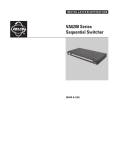
1
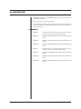
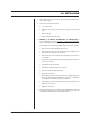
®
EH5700L
Legacy® Series
Environmental
Enclosure
Installation/
Operation Manual
C1422M-C (4/98)
Pelco • 3500 Pelco Way, Clovis • CA 93612-5699 USA • www.pelco.com
In North America and Canada: Tel (800) 289-9100 or FAX (800) 289-9150
International Customers: Tel (1-559) 292-1981 or FAX (1-559) 348-1120
CONTENTS
Section
Page
1.0 GENERAL .................................................................................................. 3
1.1 IMPORTANT SAFEGUARDS AND WARNINGS ............................... 3
2.0 DESCRIPTION .......................................................................................... 4
2.1 MODELS ............................................................................................ 4
3.0 INSTALLATION .......................................................................................... 5
4.0 OPERATION .............................................................................................. 9
5.0 MAINTENANCE ......................................................................................... 9
5.1 SERVICE MANUAL ........................................................................... 9
6.0 SPECIFICATIONS .................................................................................... 10
7.0 WARRANTY AND RETURN INFORMATION ........................................... 12
LIST OF ILLUSTRATIONS
Figure
1
2
3
Page
Exploded Assembly Diagram for Blower ............................................ 6
EH5700L Series Input Wiring Diagram .............................................. 8
EH5700L Dimension Drawing ........................................................... 11
REVISION HISTORY
Manual #
Comments
C1422M
6/95
Original manual.
C1422M-A
2/96
Expanded installation instructions; added troubleshooting information; changed heater specifications.
C1422M-B
3/96
Modified installation instructions, Figure 1, and Table A
per ECO #96-107, which added power supply barriers
and cover to circuit board. Expanded window wiper
installation instructions.
8/96
Changed specifications for maximum camera size in -1,
-2 and -3 models. Changed specification for window
viewing area.
4/98
Removed installation instructions for accessories, which
have their own manuals. Moved service information and
exploded assembly drawings to new manual, C1431SM.
Changed manual to new format.
C1422M-C
2
Date
Pelco Manual C1422M-C (4/98)
1.0 GENERAL
1.1 IMPORTANT SAFEGUARDS AND WARNINGS
Prior to installation and use of this product, the following WARNINGS should be
observed.
1.
Installation and servicing should only be done by Qualified Service Personnel
and conform to all Local codes.
2.
Unless the unit is specifically marked as a NEMA Type 3, 3R, 3S, 4, 4X, 6, or
6P enclosure, it is designed for indoor use only and it must not be installed
where exposed to rain and moisture.
3.
Only use replacement parts recommended by Pelco.
4.
After replacement/repair of this unit’s electrical components, conduct a resistance measurement between line and exposed parts to verify the exposed
parts have not been connected to line circuitry.
5.
The installation method and materials should be capable of supporting four
times the weight of the enclosure, pan/tilt, camera and lens combination.
The product and/or manual may bear the following marks:
This symbol indicates that dangerous voltage constituting a
risk of electric shock is present within this unit.
This symbol indicates that there are important operating and
maintenance instructions in the literature accompanying this
unit.
CAUTION:
RISK OF
ELECTRIC SHOCK.
DO NOT OPEN.
CAUTION:
TO REDUCE THE RISK OF ELECTRICAL SHOCK,
DO NOT REMOVE COVER. NO USERSERVICEABLE PARTS INSIDE. REFER SERVICING
TO QUALIFIED SERVICE PERSONNEL.
Please thoroughly familiarize yourself with the information
in this manual prior to installation and operation.
Pelco Manual C1422M-C (4/98)
3
2.0 DESCRIPTION
Environmental enclosures in the EH5700L Legacy® Series are used with Pelco’s
PT780 Series pan/tilt unit.
The enclosures are constructed of aluminum.
You can install cameras with either fixed focal length lenses or motorized zoom
lenses. All models have an adjustable camera sled to accommodate different sizes
of cameras and lenses.
2.1 MODELS
4
EH5723L
Environmental enclosure with rear-opening lid. Lid has gas
spring to hold it open. 23-inch (58.42 cm) length.
EH5723L-1
EH5723L with 120 VAC thermostatically controlled heater and
blower.
EH5723L-2
EH5723L with 24 VAC thermostatically controlled heater and
blower.
EH5723L-3
EH5723L with 230 VAC thermostatically controlled heater and
blower.
EH5729L
Environmental enclosure with rear-opening lid. Lid has gas
spring to hold it open. 29-inch (73.66 cm) length.
EH5729L-1
EH5729L with 120 VAC thermostatically controlled heater and
blower.
EH5729L-2
EH5729L with 24 VAC thermostatically controlled heater and
blower.
EH5729L-3
EH5729L with 230 VAC thermostatically controlled heater and
blower.
Pelco Manual C1422M-C (4/98)
3.0 INSTALLATION
1.
Unlatch and raise the enclosure lid. The gas spring will hold the lid in place
when it is fully opened.
2.
Remove the camera sled from the rail:
3.
a.
Loosen the screws.
b.
Slide the sled so that the screws are in the large part of the mounting
slots.
c.
Remove the sled.
d.
Remove the parts tied to the sled.
EH5723L-1, -2, -3 Models, and EH5729L-1, -2, -3 Models Only - If
you are installing the enclosure in a marine or high-moisture environment,
make the following modifications to your enclosure:
Refer to Figure 1 for an exploded assembly diagram of the blower assembly.
4.
Pelco Manual C1422M-C (4/98)
a.
Disconnect the electrical plug (3) from the fan (4).
b.
Remove the three sets of screws and washers (A, B, and C) that secure
the fan plate (5) and fan (4) to the enclosure.
c.
Remove the four screws and washers (B and D) that secure the fan to
the fan plate.
d.
Turn the fan around so that it blows toward the viewing window (refer to
the arrows on the fan).
e.
Reinstall the fan on the fan plate.
f.
Reinstall the fan plate and fan in the enclosure.
g.
Reconnect the electrical plug on the fan.
h.
Close the enclosure lid.
i.
On the bottom of the enclosure, remove the vent (1) grill and filters (2) at
the front of the unit. Replace the grill with one of the vent cover plates that
was attached to the camera sled as loose equipment.
j.
On the bottom of the enclosure, attach the other vent cover plate over the
grill at the rear of the unit.
k.
Open the enclosure lid.
Mount the camera/lens to the sled with the 1/4-20 Phillips-head screws that
are provided in the parts bag. You can mount the camera to either side of the
U-shaped sled, depending on the camera height required.
5
3
C
4
D
5
B
C
A B
B
A
TO FAN
BLACK
22 GA. (1 FT.)
RED
22 GA. (1 FT.)
TO PC BOARD
2
24 VAC MODELS
1
Figure 1. Exploded Assembly Diagram for Blower
5.
6
Install the sled and camera/lens in the enclosure:
a.
If the camera’s lens is adjustable, extend the lens to its maximum length.
b.
Place the sled over the mounting screws in the enclosure.
c.
Slide the sled forward until the camera’s lens almost touches the window.
d.
Tighten the screws to secure the camera sled to the enclosure.
6.
Connect the video cable in the enclosure to the video output connection on
the camera.
7.
If you are going to synchronize cameras, connect the synchronization cable in
the enclosure to the synchronization connection on the camera.
8.
If your camera has a motorized zoom lens control, connect or wire the camera’s
lens control to the LENS or LENS CONTROL connector on the circuit board.
Refer to Figure 2 to see where to connect different lens connector options.
Pelco Manual C1422M-C (4/98)
WARNING: Camera
damage possible. You
can damage your camera
if you connect it to the
wrong connector.
If your camera will use the same
power as the enclosure, plug the
camera into the CAM 1 socket on
the circuit board inside the enclosure.
9.
Wire power from the circuit board to the camera (refer to Figure 2).
There are two ways to supply power to the camera: when the power requirements for the camera and enclosure’s accessories are the same (for example,
if the camera and accessories use 24 VAC), and when the power requirements for the camera and the enclosure’s accessories are different (for example, if the camera uses 24 VAC and the accessories use 120 VAC).
When the power requirements are the same:
There are two ways to connect power:
a.
If your camera’s voltage will be different from the enclosure’s voltage,
plug the camera into the CAM 2
socket only. DO NOT plug the
camera into the CAM 1 socket or
you can damage your camera.
CAM 1 has enclosure voltage on
it.
Remove the plastic cover over the power supply section of the circuit
board.
Connect the plug to the CAM 1 socket on the circuit board.
Replace the plastic cover.
BE CAREFUL - REMEMBER
CAM 1 IS ENCLOSURE
POWER
NEVER PLUG YOUR
CAMERA INTO CAM 1 IF
THE CAMERA’S VOLTAGE
IS DIFFERENT FROM THE
ENCLOSURE’S VOLTAGE.
A three-pin plug is supplied as loose equipment. Connect the wires from
the plug to the camera as follows:
Brown - AC HI
Blue - AC NT
Green - Ground
or
b.
If both the camera and enclosure use 120 VAC and you ordered the
optional 120 VAC electrical outlet accessory (O/l OUTLET), connect the
120 VAC plug to the camera. Connect the three-pin plug to CAM 1 (remove
the plastic cover over the circuit board and replace the cover after you
plug in the connector).
When the power requirements are different:
A two-pin plug is supplied as loose equipment. Connect the wires from the
plug to the camera as follows:
Brown - AC Hl
Blue - AC NT
Connect the plug to the CAM 2 socket on the circuit board.
10. Adjust the focus and iris on the camera, if necessary.
11. Close the enclosure lid and mount the enclosure to the pan/tilt unit:
WARNING: Failure to
tighten the screws may
result in damage to the
enclosure when you operate the camera.
Pelco Manual C1422M-C (4/98)
a.
Lift the enclosure over the pan/tilt unit and carefully lower the enclosure
into the pan/tilt unit to mate the 26-pin RediLINK™ D-type connectors in
the shaft of the pan/tilt unit and on the bottom of the enclosure.
b.
Once the connectors are mated, apply firm pressure downward and to
the back of the enclosure to fully seat the enclosure in the pan/tilt unit.
c.
Slowly remove your hands from the enclosure, making sure that the enclosure is balanced on the pan/tilt unit.
d.
With the 5/32 Allen wrench that is supplied with the enclosure, tighten
the two set screws on the back of the enclosure where it mounts to the
pan/tilt unit.
7
Figure 2. EH5700L Series Input Wiring Diagram
RED
BLK
1 2
PLUG
PCB9000277ASSY
CPC CONN.
KIT # O/I-IPP
432189765
BLK
BLK
5
J1
LENS
PELCO
LENS
CONN
P1
1
LENS CONN OPTIONS
LENS CONN W/PRESETS
(SUPPLIED WITH PCB)
1 2
PLUG
PLUG
1
2
3
4
WHT
1
2
3
4
5
TB1
6
TB4
1 2
7
P3
8
9
CAM 2
10
PLUG
1 2
PCB9000276 (O/I-PCB)
1
INPUTS
1
SPARES
OPTIONAL
CAMERA
POWER
(SUPPLIED
WITH PCB)*
P2
P7
PLUG
1 2 3
TB2
AC HI NT GND
1
P5
1
RED
CAMERA POWER
24/120/230 VAC
(SUPPLIED
WITH PCB)*
TH2
TH1
HTRS
1
1
HEATER
24/120/230 V
KIT # HK57-1
KIT # HK57-2
KIT # HK57-3
HEATER
24/120/230 V
LENS CONTROL
LENS
COM
FAN
120/230 V
FOCUS
BLK
ZOOM
RED
IRIS
KIT # BK57-1 (120 V)
KIT # BK57-3 (230 V)
PRST
COM
FAN
24 VDC
PRST
ZOOM
KIT # BK57-2
WHT/ORG
WHT/BRN
WHT/RED
WHT/BLU
BLK/WHT
YEL/WHT
RED/WHT
GRN/WHT
NOT USED
PRST
FOCUS
WHT
PRST
HI
1
FAN
FAN
HTR
P6
DEF
1
PLUG 2
PLUG
1 2 3
W/W
OUTLET
PLUG
120 V
KIT # O/I-OUTLET
1 2
TB3
WIPEON
WASH ON
RED
CAM
CAM
BRN
BLU
W/W
CAM 1
BRN
BLU
GRN
CAUTION
HIGH
VOLTAGE
BLK
WHT
GRN
DEFROSTER
24/120/230 V
1 2 3 4
PLUG
BLK
BLU
WHT
TRF21240.70.7CM
BRN
BRN/WHT
BLU/WHT
BLU
BLK
BLK/WHT
24 VAC
KIT # WW57-2
PCB9000275
120/230 VAC
PCB9000275
KIT # WW57-1, -3
TO SWITCH FROM -1, TO -3,
USE JUMPER ON PC BOARD
CONNECT CAM 2 TO CAMERA WHEN THE CAMERA’S
POWER IS DIFFERENT FROM THE AC POWER INPUT.
M
M
* CONNECT CAM 1 TO CAMERA WHEN THE CAMERA’S
POWER IS THE SAME AS THE AC POWER INPUT.
1 2 3 4
PLUG
BLK
BLU
WHT
KIT # WD57-1
KIT # WD57-2
KIT # WD57-3
BLU
WHT
WHT
BLK
WHT
BLU
BLK
WHT
8
Pelco Manual C1422M-C (4/98)
4.0 OPERATION
If your enclosure has a thermostatically controlled blower, the thermostat is set to
turn the fan on between 77° and 93°F (25° and 34°C) and to turn the fan off between 62° and 78°F (17° and 26°C).
If you enclosure has thermostatically controlled heaters or defroster, the thermostat is set to turn them on between 42° and 58°F (6° and 14°C) and to turn them off
between 72° and 88°F (22° and 31°C).
5.0 MAINTENANCE
Perform the following maintenance at regularly scheduled intervals to prolong the
operational life and appearance of the equipment.
1.
Clean the window with a mild nonabrasive detergent in water and a soft cloth
to maintain picture clarity.
2.
If your enclosure has a blower, clean the foam filters as follows:
On the bottom front of the enclosure, remove the two screws in the vent grill.
Remove the vent grill and take out the filters.
Clean the filters with warm water and mild detergent, dry thoroughly, and replace them in the grill.
Reinstall the vent grill.
To order replacement filters, use the part number EH550010045.
5.1 SERVICE MANUAL
If you need to service your unit, obtain a service manual in on of the following ways:
Pelco Manual C1422M-C (4/98)
•
Go to Pelco’s web site at www.pelco.com and find service manual C1431SM.
•
Contact Pelco’s Literature Department and request service manual C1431SM.
9
6.0 SPECIFICATIONS
ELECTRICAL
Input Voltage:
24, 120 or 230 VAC, 50/60 Hz
Electrical
Connections:
One each of the following:
3-connector terminal block for power input
6-pin lens connector
9-connector terminal block for lens wiring
10-connector terminal block for camera/lens wiring
2-connector terminal block for spare connections
3-pin socket for camera power input
2-pin socket for optional camera power input
2-pin socket for blower
2-pin socket for defroster
4-pin socket for heaters
4-pin socket for wiper/washer
2-pin socket for wiper/washer controls
BNC for video
BNC for camera synchronization
26-pin RediLINK™ D-type connector
(links enclosure to pan/tilt)
Input Power:
Heater -2:
Heater -3:
Defroster -1,
-2, -3:
Blower -1, -3 :
Blower -2
Wiper -1, -2, -3:
Heater -1 90 watts
50 watts
70 watts
30 watts
15 watts
10 watts
15 watts
MECHANICAL
Construction:
Aluminum, 0.080 inches (0.20 cm) thick
(Enclosure body and lid)
Finish:
Gray polyester powder coat
Window:
Glass. 0.25-inch (0.64 cm) thick
Window
Viewing Area:
3.8" H x 4.8" W (9.65 cm x 12.19 cm)
Camera Mounting: Removable camera sled that can be inverted to accommodate
various heights of cameras and lenses
Maximum
Camera and
Lens Size
EH5723L:
15.5" L x 7.5" W x 5.5" H (39.37 cm x 19.05 cm x 13.97 cm)
EH5723L-1,
-2, -3:
15.5" L x 6.25" W x 5.5" H (39.37 cm x 15.88 cm x 13.97 cm)
EH5729L:
21.5" L x 7.5" W x 5.5" H (54.61 cm x 19.05 cm x 13.97 cm)
EH5729L-1,
-2, -3:
21.5" L x 6.25" W x 5.5" H (54.61 cm x 15.88 cm x 13.97 cm)
10
Latches:
Stainless Steel
Dimensions:
See Figure 3
Pelco Manual C1422M-C (4/98)
Weight
EH5723L:
EH5723L-1,
-2, -3:
EH5729L:
EH5729L-1,
-2, -3:
Unit
12.5 lb (5.68 kg)
Shipping
14 lb (6.37 kg)
14 lb (6.37 kg)
17 lb (7.73 kg)
16 lb (7.28 kg)
19 lb (8.64 kg)
19 lb (8.64 kg)
21 lb (9.55 kg)
GENERAL
NEMA Rating:
3R (4 when vent cover plates are used)
IEC 144 Rating:
IP54 (EH5700L-1, -2, -3)
Environment:
Indoor/outdoor; -10° to 120°F (-23° to 49°C)
(Design and product specifications subject to change without notice.)
NOTE: VALUES IN PARENTHESES ARE CENTIMETERS; ALL OTHERS ARE INCHES
Figure 3. EH5700L Dimension Drawing
Pelco Manual C1422M-C (4/98)
11
7.0 WARRANTY AND RETURN INFORMATION
WARRANTY
Pelco will repair or replace, without charge, any merchandise proved defective in material or
workmanship for a period of one year after the date of shipment.
Exceptions to this warranty are as noted below:
• Five years on FT/FR8000 Series fiber optic products.
• Three years on Genex® Series products (multiplexers, server, and keyboard).
• Three years on Camclosure® and fixed camera models, except the CC3701H-2, CC3701H-2X,
CC3751H-2, CC3651H-2X, MC3651H-2, and MC3651H-2X camera models, which have a fiveyear warranty.
• Two years on standard motorized or fixed focal length lenses.
• Two years on Legacy®, CM6700/CM6800/CM9700 Series matrix, and DF5/DF8 Series fixed
dome products.
• Two years on Spectra®, Esprit®, ExSite™, and PS20 scanners, including when used in
continuous motion applications.
• Two years on Esprit® and WW5700 Series window wiper (excluding wiper blades).
• Eighteen months on DX Series digital video recorders, NVR300 Series network video
recorders, and Endura ™ Series distributed network-based video products.
• One year (except video heads) on video cassette recorders (VCRs). Video heads will be
covered for a period of six months.
• Six months on all pan and tilts, scanners or preset lenses used in continuous motion applications
(that is, preset scan, tour and auto scan modes).
Pelco will warrant all replacement parts and repairs for 90 days from the date of Pelco shipment.
All goods requiring warranty repair shall be sent freight prepaid to Pelco, Clovis, California. Repairs
made necessary by reason of misuse, alteration, normal wear, or accident are not covered under
this warranty.
Pelco assumes no risk and shall be subject to no liability for damages or loss resulting from the
specific use or application made of the Products. Pelco’s liability for any claim, whether based on
breach of contract, negligence, infringement of any rights of any party or product liability, relating
to the Products shall not exceed the price paid by the Dealer to Pelco for such Products. In no event
will Pelco be liable for any special, incidental or consequential damages (including loss of use, loss
of profit and claims of third parties) however caused, whether by the negligence of Pelco or
otherwise.
The above warranty provides the Dealer with specific legal rights. The Dealer may also have
additional rights, which are subject to variation from state to state.
If a warranty repair is required, the Dealer must contact Pelco at (800) 289-9100 or (559) 292-1981
to obtain a Repair Authorization number (RA), and provide the following information:
1. Model and serial number
2. Date of shipment, P.O. number, Sales Order number, or Pelco invoice number
3. Details of the defect or problem
If there is a dispute regarding the warranty of a product which does not fall under the warranty
conditions stated above, please include a written explanation with the product when returned.
Method of return shipment shall be the same or equal to the method by which the item was received
by Pelco.
RETURNS
Pelco, the Pelco logo, Camclosure, Esprit,
Genex, Legacy, and Spectra are registered
trademarks of Pelco.
Endura and ExSite are trademarks of Pelco.
© Copyright 1998, Pelco. All rights reserved.
12
In order to expedite parts returned to the factory for repair or credit, please call the factory at (800)
289-9100 or (559) 292-1981 to obtain an authorization number (CA number if returned for credit,
and RA number if returned for repair).
All merchandise returned for credit may be subject to a 20% restocking and refurbishing charge.
Goods returned for repair or credit should be clearly identified with the assigned CA or RA number
and freight should be prepaid. Ship to the appropriate address below.
If you are located within the continental U.S., Alaska, Hawaii or Puerto Rico, send goods to:
Service Department
Pelco
3500 Pelco Way
Clovis, CA 93612-5699
If you are located outside the continental U.S., Alaska, Hawaii or Puerto Rico and are instructed
to return goods to the USA, you may do one of the following:
If the goods are to be sent by a COURIER SERVICE, send the goods to:
Pelco
3500 Pelco Way
Clovis, CA 93612-5699 USA
If the goods are to be sent by a FREIGHT FORWARDER, send the goods to:
Pelco c/o Expeditors
473 Eccles Avenue
South San Francisco, CA 94080 USA
Phone: 650-737-1700
Fax: 650-737-0933
Pelco Manual C1422M-C (4/98)