1
MACH-05
PATTERSON-KELLEY
MACH SERIES BOILER
GAS-FIRED BOILER
C.S.A Design-Certified
Complies with ANSI Z21.13/CSA 4.9
Gas-Fired Low Pressure Steam and Hot Water
Boilers
ASME Code, Section IV
Certified by Patterson-Kelley
C.S.A Design-Certified
Complies with ANSI Z21.13/CSA 4.9
Gas-Fired Low Pressure Steam and Hot Water
Boilers
Installation Date: _______________________
100 Burson Street, P.O. Box 458,
East Stroudsburg, PA 18301
Telephone: (877) 728-5351, Facsimile: (570) 476-7247
www.pkboilers.com
MACH® Series Gas-Fired Boiler
MACH® Series Gas-Fired Boiler
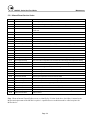
Table of Contents
1.0 INTRODUCTION ........................................1
3.6.11 Intake Duct Connection to Boiler ......... 12
2.0 SAFETY......................................................1
3.6.12 Intake Duct Terminations ..................... 12
2.1 General ..............................................................1
3.6.13 Vent Elbows ......................................... 13
2.2 Training..............................................................1
3.7 Gas Piping ....................................................... 13
2.3 Safety Features .................................................1
3.7.1 Gas Supply Piping by Installer ............... 14
2.4 Safety Labels .....................................................2
3.8 Boiler Water Piping.......................................... 14
2.5 Safety Precautions ............................................2
3.8.1 Piping Design ......................................... 14
2.5.1 Electrical Hazards ....................................2
3.8.2 Boiler Inlet and Outlet Connections ....... 15
2.5.2 Burn, Fire, and Explosion Hazards ..........2
3.8.3 Boiler Water Piping by Installer.............. 16
2.5.3 Crush Hazards .........................................3
3.8.4 Flushing and Filling ................................ 16
2.5.4 Chemical Hazards....................................3
3.9 Burner and Ignition System ............................. 17
2.5.5 Pressure Hazards ....................................4
3.9.1 Inspection............................................... 17
2.5.6 Slip, Fall Hazards .....................................4
3.10 Pre-Start Check List ...................................... 18
3.0 INSTALLATION..........................................5
3.11 Safety Checks ............................................... 18
3.1 Receiving and Storage ......................................5
3.11.1 Test of Ignition Safety System ............. 18
3.1.1 Initial Inspection .......................................5
3.11.2 Test of Low Water Cut-out ................... 19
3.1.2 Storage Prior to Installation......................5
3.11.3 Test of High-Limit Control .................... 19
3.2 Compliance with Codes.....................................5
3.11.4 Test of Gas Pressure Switch ............... 19
3.3 Setup .................................................................5
3.12 Initial Adjustments ......................................... 20
3.3.1 Foundation ...............................................5
3.12.1 Operating Temperature Controller ....... 20
3.3.2 Placement ................................................5
3.12.2 Gas Pressure Adjustment .................... 24
3.3.3 Clearances ...............................................6
3.12.3 Air Flow Adjustments ........................... 25
3.4 Electrical Connections .......................................6
3.12.4 Gas Valve Setup and Adjustment........ 25
3.5 Combustion Air ..................................................7
4.0 OPERATION ............................................28
3.5.1 Air Inlet Requirements..............................7
4.1 General ............................................................ 28
3.6 Flue Venting.......................................................8
4.1.1 Control Panel Front................................ 28
3.6.1 Barometric Damper ..................................8
4.1.2 Tests ...................................................... 28
3.6.2 Flue Connection .......................................8
4.2 Normal Lighting and Shut-Down Procedures .. 28
3.6.3 Required Clearances ...............................8
4.2.1 Lighting Procedures ............................... 28
3.6.4 Vent Terminations ....................................9
4.2.2 Normal Shut Down Procedures ............. 28
3.6.5 Venting for Multiple Boilers ......................9
4.2.3 Emergency Shut-Off .............................. 29
3.6.6 Sealed Combustion Air/Venting System 10
4.3 Typical Boiler Operating Conditions ................ 29
3.6.7 Removing an Existing Boiler ..................10
5.0 MAINTENANCE .......................................30
3.6.8 Intake/Exhaust Layout ...........................10
5.1 Maintenance and Inspection Schedule ........... 30
3.6.9 Intake Duct Materials and Sizes: ...........12
5.1.1 Daily ....................................................... 30
3.6.10 Sealing the Intake Duct........................12
5.1.2 Weekly ................................................... 30
MACH® Series Gas-Fired Boiler
Table of Contents
5.1.3 Monthly (During Operation)....................30
6.1.3 Wiring Series C-450............................... 40
5.1.4 Semi-Annually (every 6 months)............31
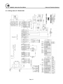
6.1.4 Wiring Series C-750/900/1050............... 41
5.1.5 Annually .................................................31
6.2 Boiler Parts List ............................................... 42
5.2 Cleaning the Burner.........................................31
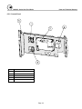
6.2.1 Main Assembly....................................... 42
5.3 After All Repairs or Maintenance.....................31
6.2.2 Control Panel ......................................... 43
5.4 Sequence of Operation....................................32
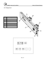
6.2.3 Display Panel ......................................... 44
5.5 Troubleshooting ...............................................32
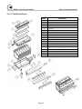
6.2.4 C-300/450 Heat Engine ......................... 45
5.5.1 Manual Reset Service Codes ................34
6.2.5 C-750/900/1050 Heat Engine ................ 46
5.5.2 Auto-reset Service Codes ......................35
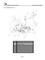
6.2.6 C-300 Boiler Gas Train .......................... 47
6.0 PARTS/TECHNICAL SUPPORT..............36
6.2.7 C-450 Boiler Gas Train .......................... 48
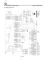
6.1 Wiring Diagrams ..............................................37
6.2.8 C-750/900/1050 Boiler Gas Train .......... 49
6.1.1 Terminal Block Assignments – High Voltage
Circuit (TB2)...............................................37
7.0 LIMITED WARRANTY .............................50
8.0 APPENDIX ...............................................52
6.1.1a Terminal Block Assignments – Low Voltage
Circuit (TB1)...............................................38
6.1.2 Wiring Series C-300 ...............................39
!
WARNING
Improper use may
result in fire or injury.
Read instructions/safety
manual before installing,
operating or servicing boiler.
c 1998 HCS, Inc. 800-748-0241
Reorder No. 6020-V2WHPK
WARNING!
Chemicals, fuels, or other potentially hazardous
or toxic materials must not be stored in the same
room as the boiler.
WARNING!
It is essential to read, understand, and follow the
recommendations of this manual before installing,
operating, or servicing this equipment. Failure to
do so could result in fire or explosion and serious
injury, death, and/or property damage.
WARNING!
Installation and service must be performed by a
qualified installer or service agency who has been
trained on the Patterson-Kelley MACH Boiler.
What to do if you smell gas:
The same features which permit this boiler to achieve
high-efficiency performance make it unlike most other
boilers of this general size, so it is important to
understand how this boiler operates.
WARNING
Do not store or use gasoline or other flammable
vapors or liquids in the vicinity of this or any other
appliance.
•
•
•
•
Do not try to light any appliance.
Do not touch any electrical switch.
Do not use any phone in your building.
Immediately call your gas supplier from a
neighbor's phone. Follow the gas supplier's
instructions.
If you cannot reach your gas supplier call the fire
department.
MACH® Series Gas-Fired Boiler
Safety
1.0 INTRODUCTION
The P-K MACH® Series Gas-Fired Boilers are fully
modulating using a variable speed combustion blower,
sophisticated microprocessor controls, modulating gas
safety shut off / control valves and a unique aluminum
alloy heat exchanger capable of operating in a fully
condensing mode to provide maximum efficiency in a
minimum amount of space. The high-quality materials
and thoroughly tested design of the boiler should
provide years of trouble-free service if the instructions
in this manual are followed carefully.
This manual covers installation of P-K MACH Series
Boilers. The model numbers may be followed by a
prefix or suffix letter in some cases to indicate special
features or different options.
While details may differ slightly, basic operation is the
same for all models. Boilers may be built to operate
with natural gas or liquefied petroleum gas (propane).
Check the rating plate for correct fuel usage and gas
pressures.
The boiler is only a part of the complete heating
system. This boiler may be fully operational and yet
because of poor circulation, control, or other operating
characteristics, not deliver heat to the desired location.
Additional equipment such as temperature sensors,
pumps, flow switches, balancing valves, and check
valves will be required for satisfactory operation of
any system. Patterson-Kelley cannot be responsible
for the design or operation of such systems and a
qualified engineer or contractor must be consulted.
2.0 SAFETY
•
Operated and serviced in accordance with a
comprehensive safety program determined and
established by the customer. Do not attempt to
operate or service until such a program has been
established.
•
Operated and serviced by qualified, properly
trained personnel in accordance with all applicable
codes, laws, and regulations.
Note: Each safety device must be maintained and
checked per the recommended schedule; refer to
Section 5.1 of this manual.
2.2 TRAINING
!
WARNING
Improper use may
result in fire or injury.
Read instructions/safety
manual before installing,
operating or servicing boiler.
c 1998 HCS, Inc. 800-748-0241
Reorder No. 6020-V2WHPK
It is essential to read, understand, and follow the
recommendations of this manual before installing,
operating, or servicing this equipment. Failure to do
so could result in property damage, serious injury, or
death.
Proper training is the best protection against accidents.
Operating and service personnel must be thoroughly
familiar with the basic construction of the P-K MACH
Series boiler, the use and locations of the controls, the
operation of the boiler, adjustment of its various
mechanisms, and all applicable safety precautions. If
any of the provisions of this manual are not fully and
completely understood, contact the Patterson-Kelley
Sales Department toll-free at (877) 728-5351 for
assistance.
2.1 GENERAL
The MACH Series gas-fired boiler must be:
2.3 SAFETY FEATURES
•
Installed, operated, and serviced in accordance
with instructions contained in this manual.
•
Installed by qualified personnel in accordance with
designs prepared by qualified facility engineers
including: structural, mechanical, electrical, and
other applicable disciplines.
Page 1
It is the responsibility of the customer to maintain the
safety features, such as: guards, safety labels, safety
controls, interlocks, lockout devices, etc., in place and
operable.
MACH® Series Gas-Fired Boiler
Safety
2.5.2 Burn, Fire, and Explosion Hazards
2.4 SAFETY LABELS
NOTE
When opening leak test valves,
always follow instructions in
operation and safety manual.
c 1998 HCS, Inc. 800-748-0241
Reorder No. 8032-01NHPK
General Warning
!
Hot Surface
WARNING
!
Improper use may
result in fire or injury.
Read instructions/safety
manual before installing,
operating or servicing boiler.
c 1998 HCS, Inc. 800-748-0241
Read instructions/safety
manual before installing,
operating or servicing boiler.
Reorder No. 6020-V2WHPK
c 1998 HCS, Inc. 800-748-0241
!
WARNING
Reorder No. 6020-V2WHPK
NOTE
Electrical hazard.
Follow lockout/tagout
procedure when
servicing this boiler.
C 1998 HCS, Inc. 800-748-0241
WARNING
Improper use may
result in fire or injury.
Make sure this union is
tight before closing cabinet
cover after servicing boiler.
Reorder No. 5025-V1WHPK
c 1998 HCS, Inc. 800-748-0241
NOTE
The safety labels shown above are affixed to your
boiler. Although the labels are of high quality, they
may become dislodged or unreadable over time.
Contact Patterson-Kelley toll-free at (877) 728-5351
for replacement labels.
When opening leak test valves,
always follow instructions in
operation and safety manual.
c 1998 HCS, Inc. 800-748-0241
Provide a suitable location for the boiler, away from
normal personnel traffic, with adequate working space,
adequate clearances, proper ventilation and lighting,
with a structure sufficiently strong and rigid to support
the weight of the boiler, all piping, and accessories.
2.5.1 Electrical Hazards
Burn, fire, and explosion hazards! Installation
must be in strict conformance to all applicable
codes and standards including NFPA 54, ANSI
Z223.1 and CAN/CGA B.149. Install all required
vent lines for gas devices. Refer to Section 3.7.1.
•
Hazard from incorrect fuels! Possible fire,
explosion, overheating, and damage. Do not use
any fuels except the design fuels for the unit.
•
Overfire hazards! High pressure in gas or propane
supply could result in overfiring of other devices
supplied from the same source.
•
Fire and explosion hazards! Close the main gas
shutoff before servicing boiler.
•
Fire and explosion hazards! Do not store or use
gasoline or other flammable vapors or liquids in
the vicinity of this or any other gas fired appliance.
•
Burn hazard! Possible hot surfaces. Do not touch
gas vent during firing operation. Use only factory
recommended vent components.
•
Burn hazard! Pipes, vents, and boiler components
could be hot. Do not touch piping or stack
surfaces during operation or immediately after
shutdown of the boiler.
WARNING
Electrical hazard.
Follow lockout/tagout
procedure when
servicing this boiler.
C 1998 HCS, Inc. 800-748-0241
•
•
Reorder No. 5025-V1WHPK
Shock hazard! Properly lockout/tagout the
electrical service and all other energy sources
before working on or near the boiler.
Shock hazard! Do not spray water directly on any
electrical components.
Page 2
Reorder No. 8032-01NHPK
•
2.5 SAFETY PRECAUTIONS
!
Reorder No. 8032-02NHAK
MACH® Series Gas-Fired Boiler
Safety
•
Burn hazard! Hot fluids. Use caution when
servicing or draining boiler.
•
Fire and explosion hazards! Use caution when
servicing burner. Propane (LPG) is heavier than
air and may linger in the combustion chamber,
vent lines, or elsewhere.
•
Gas leak hazard! Make sure the burner is installed
correctly and burner hood is securely fastened
following any maintenance performed on them.
These connections cannot be tested after the
burner is assembled.
•
Gas leak hazard! All threaded gas connections
must be made using a pipe compound that is
resistant to liquefied petroleum. Do not use
Teflon™ tape on threaded gas piping.
2.5.3 Crush Hazards
General Warning
•
•
•
•
•
Gas leak hazard! Check entire gas train for leaks
after installation. If there is a smell of gas, shut
down the boiler and obtain immediate assistance
from trained service personnel and/or your local
fire department.
Overfire hazard! Possible fire and explosion from
excess gas pressure. Make sure that gas inlet
pressure does not exceed 14 inches W.C. to the
regulator.
Overfire hazard! Possible fire and explosion.
Possible malfunction of regulators and/or gas
safety shut off / control valves. Maintain all gas
train components in good condition. Do not alter
wiring connections. Annual inspection by factorytrained personnel for proper set-up and operation
is recommended.
Overfire and underfire hazards! Possible fire,
explosion, overheating, and component failure.
Do not attempt to adjust firing rate of the boiler.
The firing rate must be adjusted only by factory
trained personnel.
•
Lifting hazards! Use properly rated lifting
equipment to lift and position the boiler. The load
is unbalanced. Test balance before lifting 3 ft.
above the floor. Do not allow personnel beneath
the lifted load. Refer to approximate weights in
the table below:
Boiler Size
Weight in Pounds
300,000 Btu
354
450,000 Btu
440
750,000 Btu
650
900,000 Btu
700
1,050,000 Btu
750
Bump hazard from overhead ductwork and piping.
Install components with adequate vertical
clearance.
2.5.4 Chemical Hazards
General Warning
Page 3
•
Chemical hazards from cleaning products. Use
caution when cleaning the system. The use of
professional assistance is recommended. Use safe
procedures for the disposal of all cleaning
solutions.
•
Combustion Condensate – a pH of approximately
4 to 5 can be expected. Use PVC or CPVC piping.
Collection and disposal must be in accordance
with all applicable regulations.
MACH® Series Gas-Fired Boiler
Safety
2.5.6 Slip, Fall Hazards
2.5.5 Pressure Hazards
!
WARNING
!
WARNING
Improper use may
result in fire or injury.
Improper use may
result in fire or injury.
Read instructions/safety
manual before installing,
operating or servicing boiler.
Read instructions/safety
manual before installing,
operating or servicing boiler.
c 1998 HCS, Inc. 800-748-0241
c 1998 HCS, Inc. 800-748-0241
•
Pressure hazard! Hot fluids. Install isolation
valves on boiler water inlet and outlet. Make sure
isolation valves are closed before servicing boiler.
•
Pressure hazard! Hot fluids. Annually test safety
relief valve for proper operation. Do not operate
boiler with faulty relief valve.
Page 4
•
Tripping hazard! Do not install piping on floor
surfaces. Maintain clear path around boiler.
•
Slip and fall hazard! Use drip pan to catch water
while draining the boiler. Maintain dry floor
surfaces.
•
Slip and fall hazard! Do not locate intake or
exhaust terminations directly above a walkway;
dripping of condensation can cause icing of the
walking surface.
MACH® Series Gas-Fired Boiler
Installation
3.0 INSTALLATION
Code, Section IV for 50 psig maximum operating
pressure and/or 200º F maximum temperature.
3.1 RECEIVING AND STORAGE
Other codes or approvals which apply will be labeled
on the boiler.
3.1.1 Initial Inspection
Upon receiving the boiler, inspect it for signs of
shipping damage. Since some damage may be hidden,
we recommend unpacking the boiler and removing the
top cover and inspecting the boiler.
Verify that the total number of pieces shown on the
packing slip agrees with those actually received.
Important: note any damage, suspected potential
damage, or shortage of materials on the freight bill
and immediately notify the carrier. File all claims
for shortage or damage with the carrier. Claims
for hidden damages must be filed with your carrier
within 7 days. The boiler carton is equipped with a
“Tip (N) Tell”. If "Tip (N) Tell” arrow point is
blue, that indicates that the package has been on its
side or tipped over in transit.
3.1.2 Storage Prior to Installation
If the boiler is not installed immediately, it must be
stored in a location adequately protected from the
weather, preferably indoors. If this is not possible,
then it should remain in the shipping container and be
covered by a tarpaulin or other waterproof covering.
Installation of the boiler must conform to all the
requirements of all national, state and local codes
established by the authorities having jurisdiction or,
in the absence of such requirements, in the U.S. to the
National Fuel Gas Code, ANSI Z223.1/NFPA 54,
latest edition. In Canada, the equipment shall be
installed in accordance with the current Installation
Code for Gas Burning Appliances and Equipment,
CAN/CGA-B.149, and applicable Provincial
Regulations for the class, which should be carefully
followed in all cases. Authorities having jurisdiction
should be consulted before installations are made.
Where required by local codes, the installation must
conform to American Society of Mechanical
Engineers Safety Code for Controls and Safety
Devices for Automatically Fired Boilers (ASME
CSD-1).
In the Commonwealth of Massachusetts (a) this unit
must be installed by a licensed pipe fitter / plumber,
(b) field installed gas cocks must be “T” handle type,
and (c) piping of condensate shall conform with the
State Plumbing Code.
3.3 SETUP
Note: controls and other equipment that are
damaged or fail due to weather exposure are not
covered by warranty.
3.3.1 Foundation
3.2 COMPLIANCE WITH CODES
Note: The boiler may be installed on a combustible
floor; however, the boiler must never be installed on
carpeting.
Provide a firm, level foundation, preferably of
concrete.
The P-K MACH Series Boiler with standard
components and with many options complies with
American National Standard/CSA Standard ANSI
Z21.13/CSA 4.9, latest edition, Gas-Fired Low
Pressure Steam and Hot Water Boilers.
3.3.2 Placement
The boiler must be level to function properly. To
assist in leveling the boiler, the four (4) adjustable leg
bolts (1/2"- 13 NC) must be installed. The adjustable
legs are also necessary to provide adequate floor
The heat exchanger is constructed and stamped in
accordance with ASME Boiler and Pressure Vessel
Page 5
MACH® Series Gas-Fired Boiler
Installation
clearance and prevent distortion of the cabinet,
(twisting, etc.) in addition to leveling.
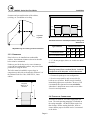
D
D
Adjustable
Leg Bolts
Minimum Clearances from Adjacent Walls, Ceiling, and
Obstructions
Type of Surface
Adjustable Legs for Leveling and Floor Clearance
3.3.3 Clearances
If the boiler is to be installed near combustible
surfaces, the minimum clearances shown in the table
below must be maintained.
Failure to provide for the service access clearances,
even with non-combustible surfaces, may cause future
problems servicing the boiler.
The boiler must be installed in a space large in
comparison to the boiler as described in Section 6.3 of
the National Fuel Gas Code, ANSI Z223.1, latest
edition.
No pipes,
ducts, etc. in
this area.
A
Dimensions (inches)
A
B
C†
D
Combustible Surfaces
36
24
24
24
Non-combustible Surfaces
36
*
24
24**
† "C" Do not put pipes, ducts, etc. in this area above
the boiler.
CAUTION!
Bumping hazard from overhead ducts! Install all
components with adequate vertical clearances.
* Clearance depends upon vent configuration.
** Service access need be only on one side of a
boiler or row of boilers. Boilers may be installed
immediately adjacent to each other. However, P-K
recommends this clearance between each boiler
when there is insufficient access at the rear to allow
for service and adjustment.
C
B
3.4 ELECTRICAL CONNECTIONS
The boiler is wired for 120 volts, single phase, 60
hertz. The total operating amperage is indicated on
the rating nameplate. All MACH units require less
than 8 amps. Before starting the boiler, check to
ensure that the proper electrical service is connected
to the boiler.
Page 6
MACH® Series Gas-Fired Boiler
Installation
An external electrical disconnect (not supplied with
the boiler) with adequate overload protection is
required. The boiler must be grounded in accordance
with local codes or in the absence of such
requirements, in the U.S. with National Electrical
Codes, ANSI/NFPA No. 70 latest edition and in
Canada to the current Canadian Electrical Code, Part I,
CSA C22.1.
Note: A dedicated earth ground (green wire) is
required to avoid nuisance shutdowns. Do not ground
through the conduit. It is also important that proper
polarity be maintained.
Note: Refer to Terminal Block Assignments (Section
6.1.1).
Low Voltage
Control Junction
Box
120 Volt
Electrical Control
Junction Box
when burned, form acids which quickly attack the
boiler and the boiler stack. The result is improper
combustion and premature boiler failure.
Provisions for combustion and ventilation air must be
in accordance with Section 5.3, Air for Combustion
and Ventilation, of the National Fuel Gas Code,
ANSI Z223.1, latest edition, or applicable provisions
of the local building codes. In Canada, combustion
air openings shall comply with CSA B.149
Installation Code. The formula is 1 sq. in. per 1,000
Btu/hr of gas input not less than 100 sq. in. The
location shall be neither more than 18", nor less than
6" above the floor level.
The boiler room shall be provided with two openings
to ensure adequate combustion air and proper
ventilation. One opening should be 6 to 12 inches
above the floor and the other 6 to 12 inches below the
ceiling, preferably on opposite walls. The size of
each opening is determined by whether air is taken
from inside or outside the building. In Canada,
ventilation air openings shall be at least 10% of the
cross sectional area required for combustion air, but
not less than 10 square inches. It is to be located at
the highest practical point communicating with
outdoors.
WARNING!
Electrical Connections at Rear of Boiler
Under no circumstances shall the boiler room
ever be under a negative pressure. Particular
care should be taken when exhaust fans,
compressors, air-handling units or other
equipment may rob air from the boiler.
3.5 COMBUSTION AIR
Combustion air must be free from dust, lint, etc. The
presence of such materials in the air supplied to the
burner could cause nuisance "Low Air" shutdowns or
premature burner failure. The boiler should not be
operated during construction while the possibility of
drywall dust, demolition dust, etc. exists.
3.5.1 Air Inlet Requirements
The combustion air supply must be completely free of
chemical fumes which may be corrosive when burned
in the boiler. Common chemicals which must be
avoided are fluorocarbons and other halogenated
compounds, most commonly present as refrigerants or
solvents, such as freon, trichlorethylene,
perchlorethylene, chlorine, etc. These chemicals,
When air is taken from the outdoors through a
vertical duct, 1 square inch per 4,000 Btu per hour is
required. If a horizontal duct is used, 1 square inch
per 2,000 Btu per hour is required, i.e., 225 square
inches for 450,000 Btu per hour input.
Page 7
If air is taken directly from outside the building, each
opening (minimum of two) should have a net free
area of 1 square inch for each 4,000 Btu per hour of
total boiler input. For instance, 112.5 square inches
are required for 450,000 Btu per hour input.
MACH® Series Gas-Fired Boiler
Installation
If air is taken from another interior space, each
opening should have a net free area of 1 square inch
for each 1,000 Btu per hour of boiler input (450 square
inches for a 450,000 Btu per hour.)
3.6 FLUE VENTING
This boiler requires a special vent system. This boiler
is not certified for use with Type "B" vent.
This boiler is Category IV (condensing – positive
pressure) as it is defined in ANSI Z21.13/CSA 4.9,
latest edition. The vent material must be listed
Category IV vent pipe (316L or AL29-4C Stainless
Steel) and comply with UL 1738 or UL103. In
Canada it must comply with ULC-636. The exhaust
vent can be run horizontally or vertically.
Vent installations shall be in accordance with Part 10,
Venting of Equipment, of the National Fuel Gas Code,
ANSI Z223.1 or CSA B.149 code, or applicable
provisions of the local building codes.
The venting system and the horizontal portions of the
venting system shall be supported to prevent sagging.
The vent must be sized according to the vent
manufacturer’s recommendations. Consult your vent
supplier for correct sizing and structural support
requirements. Design calculations should be based on
a maximum of 0.22" W.C. total frictional resistance in
the stack (measured at the boiler flue gas discharge),
with a stack temperature of 210° F (gross) and a CO2
level of 9% (natural gas) or 10.4% (propane). These
values are to be used for vent sizing calculations.
The installation of a bird screen on the vent
termination is recommended. Consult your local vent
manufacturer for proper sizing.
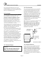
3.6.2 Flue Connection
The connection from the boiler to the vent should be
as direct as possible and the upward slope of any
horizontal breaching should be at least 1/4 inch per
linear foot. The 300 and 450 vent connection
incorporates a 4° slope toward the boiler to facilitate
pitching of the vent for condensate collection. This
boiler should not be connected into any portion of
another mechanical draft system operating under
positive pressure without consulting your local
venting representative. Provisions must be made for
supports to prevent contact of the vent with
combustible surfaces.
Note: If the vent is erected directly behind the boiler,
make sure that the weight of the vent is not
supported by the boiler vent collar. The collar is
not designed to support the weight of the vent.
Structural support and spacing from combustible
surfaces must be in accordance with the vent
manufacturer's requirements.
Sidewall
Pitch toward
boiler 1/4" per
foot minimum.
4 degree slope
toward boiler,
approx. ¾” per
foot.
Flue Connection at Boiler
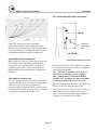
3.6.3 Required Clearances
3.6.1 Barometric Damper
Provide clearances between combustion air intake,
exhaust vent, roof and wall surfaces, doors and
window, and snow line as shown in the following
diagrams. The exhaust vent termination must be 14
feet above grade when located adjacent to a public
walkway. It must also have a minimum 6 foot
horizontal and 6 foot vertical clearance (above or
below) any electric meters, gas meters, regulators, or
relief equipment.
WARNING!
Do not use a barometric damper with this
boiler. (This is a positive pressure system;
combustion gas may leak into the room.)
Page 8
MACH® Series Gas-Fired Boiler
Installation
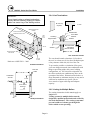
3.6.4 Vent Terminations
WARNING!
Do not locate intake or exhaust terminations
directly above a walkway; dripping of condensation can cause icing of the walking surface.
No rain cap
required,
or Tee.
Mechanical draft vent
terminal
Direct vent terminal
clearance minimum 12 in.
Outside Plate
Less
than
10 ft.
Cover Plate
Fastener
Sealant
4 ft.
min.
4 ft.
min.
3 ft min.
12 in.
min
Mechanical draft
vent terminal
Centering
Support Plate
12 in.
min.
Sealant
Recommended
Termination
(see text below)
12" min.
12 in.
min.
Grade
Vent Termination Details
Forced
air inlet
The vent should extend at least three (3) feet above
the roof, or at least two (2) feet above the highest part
of any structure within ten (10) feet of the vent.
Reference: ANSI Z223.1 - 2002
Sidewall Installations
10' min.
Flue Gas
Outlet
Combustion
Air Inlet
4' min.
To prevent the possible re-circulation of flue gases,
your vent designer must take into consideration such
things as prevailing winds, eddy zones, building
configurations, etc. P-K can not be responsible for
the effects such adverse conditions may have on the
operation of the boilers. Dimensions listed above or
those illustrated are minimum, and may or may not be
sufficient for conditions at a specific job site.
A tee must be of approved design and adequate
capacity.
4' min above
snow line
3.6.5 Venting for Multiple Boilers
The venting instructions in this manual apply to a
single boiler.
Rooftop Installations
Page 9
Venting systems for multiple boilers must be
designed by qualified professionals and verified by
the stack manufacturer. The venting system must
prevent backflow of exhaust gas through idle
boilers which are not operating.
MACH® Series Gas-Fired Boiler
Installation
3.6.6 Sealed Combustion Air/Venting System
The MACH Series Boilers are also certified for
operation with a sealed combustion air and pressurized
venting system. Such a system employs a sealed
combustion air intake duct leading from outdoors and
a sealed exhaust vent terminating outdoors. Air flow
through the system is maintained by the fan inside the
boiler assembly.
Vent Installation Details
Installation must conform to the vent manufacturer's
instructions in all respects including joining,
clearances, fastening, fire-stopping, and other matters.
3. Insofar as is practical, close all building doors
and windows and all doors between the space in
which the appliances remaining connected to the
common venting system are located and other
spaces of the building. Turn on clothes dryers
and any appliances not connected to the common
venting system. Turn on any exhaust fans, such
as range hoods and bathroom exhausts, so they
will operate at maximum speed. Do not operate a
summer exhaust fan. Close fireplace dampers.
4. Place the appliance being inspected in operation.
Follow the lighting instructions. Adjust the
thermostat so that the appliance will operate
continuously.
Vent ductwork may be run horizontally or vertically if
so certified.
5. Test for spillage at the draft hood relief opening
after 5 minutes of main burner operation. Use the
flame of a match or candle or smoke from a
cigarette, cigar or pipe.
3.6.7 Removing an Existing Boiler
(from a common venting system)
6. After it has been determined that each appliance
remaining connected to the common venting
system properly vents when tested as outlined
above, return doors, windows, exhaust fans,
fireplace dampers and any other gas-burning
appliance to their previous conditions of use.
When an existing boiler is removed from a common
venting system, the common venting system is likely
to be too large for proper venting of the appliances
remaining connected to it.
At the time of removal of an existing boiler, while the
other appliances remaining connected to the common
venting system are not in operation, the following
steps should be followed with each appliance
remaining connected to the common venting system
placed in operation:
1. Seal any unused openings in the common venting
system.
2. Visually inspect the venting system for proper size
and horizontal pitch and determine that there is no
blockage or restriction, leakage, corrosion or other
deficiency which could cause an unsafe condition.
Page 10
Any improper operation of the common venting
system should be corrected so the installation
conforms with the National Fuel Gas Code, ANSI
Z223.1 and CSA B149 Installation Code. When
resizing any portion of the common venting system,
the common vent system should be resized to
approach the minimum size as determined using the
appropriate tables.
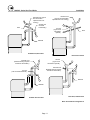
3.6.8 Intake/Exhaust Layout
Four basic configurations for the intake/exhaust may
be used. Refer to Section 3.6.3 for required
clearances for all terminations shown in the four
following figures.
MACH® Series Gas-Fired Boiler
Installation
Exhaust Vent
(Type of flue termination
optional when roof venting.)
Exhaust Vent (type of
flue termination
optional when roof
venting.)
Air Inlet (tee
mounted
horizontally.)
Roof
Air Inlet
(Type of flue
termination
optional.)
Roof
Sidewall
Sidewall Inlet, Roof Vent
Roof Inlet and Vent
Air Inlet
(Type of flue
termination optional.)
Exhaust Vent
(Sidewall venting requires
vertical tee termination.)
Exhaust Vent
(Sidewall venting requires
vertical tee termination.)
Air Inlet
(Tee mounted horizontal.)
Sidewall
Sidewall
Sidewall Inlet and Vent
Roof Inlet, Sidewall Vent
Basic Air Inlet/Vent Configurations
Page 11
MACH® Series Gas-Fired Boiler
Installation
Exhaust Vent
(Sidewall
Venting
Requires Up
Elbow Mounted)
3.6.12 Intake Duct Terminations
Roof
Round
Air inlet
(Down Elbow
Mounted)
90° Elbow
Sidewall
C750/900/1050 Sidewall Inlet and Vent
3.6.9 Intake Duct Materials and Sizes:
Material: PVC, CPVC (Schedule 40), single wall
galvanized steel, or other suitable materials.
Sidewall
Air Inlet
(tee mounted
horizontally)
The intake duct must be sized for a maximum pressure
drop of 0.22 inches W.C., for the SCFM as specified
below.
Boiler Size
Required SCFM
1050
245
900
210
750
175
450
105
300
70
Round
The installation of a bird screen on the intake
termination is recommended.
3.6.10 Sealing the Intake Duct
Proper sealing of the intake ductwork is necessary to
prevent infiltration of air from conditioned space.
Joints in PVC or CPVC must be cemented. For
galvanized duct, wrap each joint and seam with
adhesive aluminum tape.
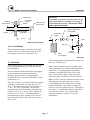
3.6.11 Intake Duct Connection to Boiler
Connect the air supply duct to the collar on the back of
the boiler. Fasten the duct to the collar with sheet
metal screws at 90º angles. Seal the joint.
Page 12
No rain cap Unrestricted
The roof intake termination must be an
unrestrictive type, as shown above.
MACH® Series Gas-Fired Boiler
Installation
WARNING!
Outside Plate
Cover Plate
Fastener
Sealant
Centering
Support Plate
Sealant
Field Provided
Inlet Screens
All threaded connections must be made using a
pipe compound that is resistant to the action of
liquefied petroleum gases. Do not use Teflon
tape on gas line threads.
Remote Gas Shutoff
(not supplied)
Recommended
Termination
Natural Gas
Supply
By Installer
12" min.
Union
Intake Termination Details
Drip Leg
3.6.13 Vent Elbows
The turn from horizontal to vertical should be made
with two 45º ells or with one long radius 90º ell for
best operation. Do not use "short radius" ells.
Meter
(not supplied)
Shutoff
(on boiler)
Gas Piping
In the Commonwealth of Massachusetts, the gas cock
must be a “T-handle type.”
3.7 GAS PIPING
Before making the gas hook-up, make sure the boiler
is being supplied with the type of fuel shown on the
boiler nameplate.
The boiler shall be installed such that the gas ignition
system components are protected from water
(dripping, spraying, rain, etc.) during appliance
operation and service (circulator replacement, control
replacement, etc.)
The boiler is factory fire-tested and adjusted for proper
combustion with natural gas supply pressure of 7”
W.C. Typical gas pressure supply for natural gas is
7" W.C. (11" W.C. for propane). The gas train
components are certified to handle a maximum inlet
pressure of 14" W.C. (1/2 psig.). If the available gas
pressure exceeds 14" W.C., a suitable additional
intermediate gas pressure regulator of the "lock up"
type must be provided to reduce the pressure to less
than 14" W.C.
Page 13
Note: Install a sediment trap (drip leg) and a union
connection ahead of the primary manual shutoff valve
on the boiler. Gas piping should be installed in
accordance with National Fuel Gas Code, ANSI
Z223.1, latest edition, and any other local codes
which may apply; in Canada see CAN/CGA-B.149.
Note: See Pipe Capacity for Natural Gas chart on the
following page for required pipe size, based on
overall length of pipe from meter plus equivalent
length of all fittings. Approximate sizing may be
based on 1 cubic foot of natural gas per 1,000 Btu per
hour input, i.e., 500,000 Btu per hour requires about
500 cubic feet per hour. (See "Typical Boiler
Operating Conditions," Section 4.3, for more
information.)
MACH® Series Gas-Fired Boiler
Installation
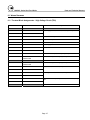
Pipe Capacity for Natural Gas
Nominal
Equivalent Pipe Length
Iron Pipe
Internal
Size
Diameter
(Inches)
(Inches)
Maximum Capacity in Cubic Feet of Natural Gas per Hour
Pressure Drop of 0.5 inch Water Column/Equivalent Length of Pipe
(in feet)
90º Ell
Tee
(Feet)
(Feet)
20
40
60
80
100
150
200
1/2
0.622
1.55
3.1
120
82
66
57
50
40
35
3/4
0.824
2.06
4.12
250
170
138
118
103
84
72
1
1.049
2.62
5.24
465
320
260
220
195
160
135
1- 1/4
1.380
3.45
6.9
950
660
530
460
400
325
280
1- 1/2
1.610
4.02
8.04
1460
990
810
690
620
500
430
2
2.067
5.17
10.3
2750
1900
1520
1300
1150
950
800
2- 1/2
2.469
6.16
12.3
4350
3000
2400
2050
1850
1500
1280
3
3.068
7.67
15.3
7700
5300
4300
3700
3250
2650
2280
4
4.026
10.1
20.2
15800
10900
8800
7500
6700
5500
4600
3.7.1 Gas Supply Piping by Installer
3.8 BOILER WATER PIPING
The boiler and all gas piping connections should be
pressure-tested and must be checked for leaks before
being placed into service. Test with compressed air or
inert gas if possible.
3.8.1 Piping Design
The boiler must be disconnected at the boiler manual
shut-off valve (located at the end of the supplied gas
train) from the gas supply piping system during any
pressure testing of the system at pressures in excess of
1/2 psig (14" W.C.).
During any pressure testing of the gas supply piping
system at pressures equal to or less than 1/2 psig (14"
W.C.), the boiler should be isolated from the gas
supply piping system by closing the manual shut-off.
Some leak test solutions, including soap and water,
may cause corrosion. These solutions should be
rinsed-off with water after testing.
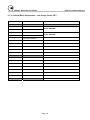
Water Flow in System
For proper water flow requirements see below.
Incorrect flow may result in eventual damage or
premature failure of the equipment.
Model
Max Flow
GPM
Min Flow
GPM
DP ft. at
max flow
1050
105
52
12
900
90
45
12
750
75
37
12
450
45
22
8.5
300
30
15
8.5
Contact factory for minimum flow at other than
maximum firing rate.
Page 14
MACH® Series Gas-Fired Boiler
Installation
3.8.2 Boiler Inlet and Outlet Connections
C750
C900
C1050
C450
C300
Proper flow rates may be achieved through a
combination of primary and secondary flow loops.
Multiple zones and pumps may result in different flow
rates at different times. Consideration must be given
to all possible conditions and their consequences.
Condensate
Trap (Piped to
drain)*
Piping With Refrigeration Machines
When installed in a two-pipe system that provides both
chilled and hot water, the control system should be
configured so as to limit the time rate of change of
temperature at the boiler. Consult your authorized
Patterson-Kelley boiler representative for application
guidance.
Piping With Air Handling Units
The boiler piping system of a hot water heating boiler
connected to heating coils located in air handling units,
where they may be exposed to refrigerated air
circulation, must be equipped with flow control valves
or other automatic means to prevent gravity circulation
of the boiler water during the cooling cycle.
Boiler Inlet and Outlet Connections
Make water connections as the application warrants,
or at a minimum as shown, but always in compliance
with the local requirements.
Note: The boiler is furnished with 2” grooved
connections for Victaulic Style 75 Couplings.
These coupling must be used with the EPDM
Victaulic seals. Isolating valves must be installed
in both water connections for ease of service.
The bottom connection to the boiler is the INLET and
must be used for the return from the system.
The top connection to the boiler is the OUTLET and
must be connected as the supply to the system.
* Note: Condensate Trap must be piped to drain in
accordance with all state and local codes.
Page 15
MACH® Series Gas-Fired Boiler
Installation
Drain Valve and Piping
3.8.3 Boiler Water Piping by Installer
Strainer
To avoid possible contamination of the boiler with
dirt, rust or sediment from the system, a strainer near
the boiler inlet is strongly recommended. Even new
systems may contain sufficient foreign material to
eventually reduce the performance of the heat
exchanger. Adequate circulation of good clean water
is essential to maximum efficiency and long life of the
boiler.
Relief Valve and Piping
Each boiler is supplied with a pressure-relief valve
sized in accordance with ASME requirements. The
relief valve should be piped to a suitable floor drain.
Reducing couplings or other restrictions are not
permitted in the discharge line.
A drain valve is installed in the inlet (system return)
header connection to the boiler. Prior to draining the
boiler for maintenance or testing, electrical power and
gas supply must be turned off to the boiler. The
boiler must then be isolated from the system at the
supply and return connections prior to draining water
from the boiler.
Note: This drain valve is installed for draining of the
boiler water only, not the entire system. Draining of
the system through the boiler will result in depositing
sediment from the system in the boiler which will
result in poor heat transfer characteristics of the boiler
and early boiler failure.
Condensate Drain
The condensate can be slightly acidic (pH between
3.0 and 5.0). This may be corrosive to some building
drain systems. A condensate neutralization system
may be required.
Disposal of condensate must comply with all state
and local codes.
Low Water Cut-off
The boiler is furnished with a probe-type low water
cut-off; no field piping is required. If the water level
in the boiler drops below the probe, the boiler will shut
down and a flashing E 12 service code will be
displayed on the control panel. The low water cutoff
circuit will automatically reset when the low water
condition clears; however the boiler controls will
retain the lockout condition until the reset button on
the display is depressed.
IMPORTANT!
3.8.4 Flushing and Filling
Water Quality
The MACH Series boiler heat exchanger is made of
an aluminum alloy. The heat exchanger requires
special water conditions to retain efficiency and
function properly.
IMPORTANT!
The low water cutout probe only prevents boiler
operation when the water level in the boiler is
insufficient. It does not detect low water
conditions in other parts of the system.
Installation of high point vents or additional low
water safety devices to protect the system should
be considered.
Installation of external limit controls may be required
by certain codes or in certain installations. Review
applicable local codes for details.
Chemicals added to the system must be
approved by the chemical manufacturer for use
in aluminum boilers.
IMPORTANT!
Under no circumstances should petroleum
based cleaning or sealing compounds be used in
the boiler system.
The boiler is designed to operate in a closed-loop
system. As such, the system should be tight and not
require make-up water. A high percentage of
Page 16
MACH® Series Gas-Fired Boiler
Installation
untreated make-up water will cause premature failure
due to buildup of scale; such failure is not covered by
warranty.
IMPORTANT!
Water pH
If the piping system attached to this unit will be
chemically cleaned, the boiler must be
disconnected from the system and a bypass
installed so that the chemical cleaning solution
does not circulate through the boiler. Following
chemical cleaning, the system should be
thoroughly rinsed to remove cleaning agents
prior to reconnecting the boiler to the system.
The pH of the hydronic system fluid must be between
6.0 and 8.5. A periodic check of the system pH should
be conducted to ensure these pH levels are maintained.
Filling
Scale can also reduce efficiency. For example, a scale
thickness of 1/16" will result in a 12.5% loss of
efficiency.
IMPORTANT!
Glycol and other additives must be approved by
the chemical manufacturer for use in aluminum
boilers and must meet the required pH levels
listed above to prevent damaging the boiler.
The water quality should be within the guidelines
established by the American Boiler Manufacturers
Association, as follows:
To be sure that the boiler is not air-bound, open the
pressure-relief valve located at the rear of the boiler.
Leave the relief valve open until a steady flow of
water is observed. Close the valve and finish filling
the system.
3.9 BURNER AND IGNITION SYSTEM
Total solids:.................................. 2,500 ppm
Total hardness: ................................ 150 ppm
3.9.1 Inspection
The amount of oils, fats, grease, and other organic
matter should be limited to 10 ppm.
Consult your water conditioning or chemical treatment
supplier for analysis and recommendations.
Flushing the System
Before filling the boiler, flush the system to remove
any debris from construction or maintenance. Clean
and flush old piping thoroughly before installing the
boiler.
IMPORTANT!
Under no circumstances should the hydronic
system be flushed while the boiler is attached to
the system since the debris or corrosion products
could accumulate in the boiler and plug the boiler
heat exchanger.
Page 17
Inspect the unit to be sure nothing was damaged or
knocked loose during shipment. Since some damage
may be hidden, remove the top cover and inspect the
boiler.
Inspect the gas train, blower, ignition electrode and
boiler in general to be sure there was no damage
during shipment or installation.
MACH® Series Gas-Fired Boiler
Installation
3.10 PRE-START CHECK LIST
WARNING!
Before attempting to start the boiler, make sure the
following items have been completed.
After checking controls by manual adjustment,
make sure they are always reset to their proper
settings.
1. Section 3.9.1 Inspection.
2. Flue gas from the boiler is properly vented; (refer
to Section 3.6)
3. Gas connection has been made, pressure tested for
leakage, and the line purged of air. Make sure all
required vents have been installed.
3.11.1 Test of Ignition Safety System
4. Water connections are complete, and the boiler
and system have been filled and purged of air.
Test the ignition system safety shutdown as follows:
5. The boiler is connected to a 120 volt power source
with a disconnect having adequate overload
protection.
6. Combustion air openings are not obstructed in any
way and have adequate capacity.
7. The boiler is placed the proper distance from any
combustible walls, in accordance with Section
3.3.3.
8. Relief valves have been piped to floor drains.
MACH (C300 & C450)
1. Loosen the retaining screw and remove the 5 pin
connector from one of the two gas safety shutoff/control valves.
2. Cycle the boiler on by generating a heat request.
(The method for this will depend on your boiler
configuration. See Section 3.12.1.2)
3. The boiler should run through the normal startup
sequence, checking all of the limits and switches
as in a normal start up. (See Sequence of
Operation, Section 5.4)
10. Verify system fluid pH level is within
specification.
4. When the boiler reaches the ignition period, a 2
will display as the first digit in the display, the
spark terminal will energize, and one of the gas
safety shut off / control valves will open. One
open gas valve should not provide sufficient fuel
to light the burner.
3.11 SAFETY CHECKS
5. After 3 seconds the combustion control should
lock out, and the display will flash E-02
indicating a flame failure.
9. Condensate piping is properly connected.
The following checks of safety systems must be made
before putting the boiler into normal operation.
Before firing the boiler refer to Sections 4.1 and 4.2
for information on the use of the controls, lighting, and
shut-down procedures.
After completing this test, turn off the boiler and
reconnect the 5 pin connector to the gas safety shut
off / control valves retightening the retaining screw.
MACH (C750, C900 & C1050)
WARNING!
Test the ignition system safety shutdown as follows:
Never attempt to operate a boiler that has failed
to pass all the safety checks described below.
1. Cycle the boiler on by generating a heat request.
(The method for this will depend on your boiler
configuration. See Section 3.12.1.2)
2. Place the boiler in operation at the high fire
setting. See section 3.12.4 Gas Valve Setup and
Adjustment , Test Mode High
Page 18
MACH® Series Gas-Fired Boiler
Installation
3.
Smoothly close the downstream manual isolation
valve to reduce the gas flow and cause flame
failure.
4
The display will flash E-02 indicating a flame
failure. The E-02 lockout will remain until reset
on the display.
After completing this test, turn off the boiler and open
the downstream manual isolation valve.
3.11.2 Test of Low Water Cut-out
The boiler is furnished with a probe-type low water
cut-out in the outlet nozzle. Test as follows:
Operation of the switch can be checked by first turning
the boiler off, and then turning the system pump off.
Isolate the boiler from the system pressure. After
isolating the system, drain the water level below the
low water cut-out probe. Turn the boiler back on. It
should not operate, and a manual reset lockout
displaying E 12 on the display panel will occur. The
LED indicator for Low Water cut-out will no longer be
illuminated.
Return the system to normal operation and restart the
boiler. Refer to Section 4.2.1.
3.11.3 Test of High-Limit Control
Fire the boiler and test the high limit control as
follows:
With the main burner operating, turn down the
temperature setting on the "high-limit" thermostat until
the main burner shuts off. A manual reset lockout
displaying E 12 on the display panel will occur. The
high-limit switch must be manually reset prior to
resetting the boiler at the display panel. Readjust the
high-limit thermostat to the desired setpoint.
3.11.4 Test of Gas Pressure Switch
Low Gas Pressure Switch
The boiler is furnished with a low gas pressure switch.
The operation of this switch must be checked by
slowly closing the main gas cock while the burner is
operating. The switch should shut down the main
Page 19
burner. When the gas pressure switch opens, a
manual reset lockout displaying E 12 on the display
panel will occur. Upon re-opening the main gas
cock, the E 12 indicator will remain on until the
display panel is manually reset.
High Gas Pressure Switch
C450 units equipped with a high pressure switch
must be checked by closing the downstream gas cock
while the burner is operating. The switch should shut
down the main burner. When the gas pressure switch
opens, a manual reset lockout displaying E 12 on the
display panel will occur. Upon re-opening the gas
cock, the E 12 indicator will remain on until the
display panel is manually reset.
C750,C900 and C1050 units equipped with a high
pressure switch must be checked by closing the
downstream gas cock with the boiler off. When the
boiler is starte , it should enter its normal starting
cycle and fail on high gas pressure when the gas
safety valves open. The high gas pressure switch
actuation is evident when a manual reset lockout
displaying E 12 on the display panel occurs. Upon
re-opening the gas cock, the E 12 indicator will
remain on until the display panel is manually reset.
MACH® Series Gas-Fired Boiler
Installation
3.12 INITIAL ADJUSTMENTS
3.12.1 Operating Temperature Controller
Mode
Description
Display
Example
Standby
(Stby)
Normal display
mode
1st digit
without a dot
0 180
Parameter
(PArA)
Parameter
settings
1st digit with
a dot
1.125
Information
(InFo)
display boiler
sensors
1st digit with a
blinking dot*
1.180*
Standby Mode:
The display defaults to this mode at startup or reset of
the control. If no key is pressed for 20 minutes the
display will return to this mode. The function of the
keys may be two-fold as shown below.
The MACH boiler is equipped with a combination
combustion and temperature control. This control
monitors combustion and lighting of the boiler, as well
as maintaining temperature of the supply water. The
temperature control portion modulates the boiler to
maintain the desired outlet temperature based on the
selected operating configuration.
CAUTION!
The user should become thoroughly familiar with
the operation of the boiler and controls before
attempting to make any adjustments.
3.12.1.1 Operation of the Control
The boiler is operated through the control/display
panel. The display has 3 modes of standard operating
menus. The modes are:
•
•
•
Standby mode will display (Stby)
Parameter mode will display (PArA)
Information mode will display (InFo)
Key(S)
Duration
Function
Mode
momentary
Change to next mode
Reset
momentary
Reset the control
Plus
momentary
Show the comfort heat
setpoint, or max setpoint
(outdoor reset only)
Plus
long*
Turn the comfort heat system
on or off
Minus
momentary
Show the domestic hot water
setpoint
Minus
long*
Turn the domestic hot water
system on or off
*Note: Long duration is greater than 2 seconds.
When in the Standby Mode the control indicates
boiler status with the first digit of the display. The
remaining digits indicate the boiler's actual
temperature or lockout code. The following table
indicates the meaning of the display digits when in
the standby level.
First Digit
At each level the keys and the display have different
functions. To ascertain which mode you are in, the
displayed information will be shown as indicated
under “display”.
Page 20
Boiler Status
0
Burner off - No call for heat
1
Pre purge or post purge
2
Ignition
3
Burner on in Comfort Heat mode
4
Burner on in Domestic Hot Water mode
5
Checking the airflow switch
6
Burner off - An internal setpoint has been
reached. System is still calling for heat.
7
Burner off - Comfort Heat pump running on
MACH® Series Gas-Fired Boiler
First Digit
Installation
Information Mode:
Boiler Status
delay. No system call for heat.
8
Burner off - Domestic Hot Water pump
running on delay. No system call for heat.
9 and b
flashing
Burner off – auto reset lockout. A code is
displayed indicating the reason for the
lockout. (See Troubleshooting Section
5.5.)
A
Adjusting the 3 way valve if used
H
Burner on in manual high fire
L
Burner on in manual low fire
The information mode is used to display the values of
the various sensors such as inlet water temp, outlet
water temp etc. The information mode is accessed by
pressing the MODE key several times until InFo is
displayed. The desired sensor is selected with the
STEP key. The following table indicates the
displayed value:
Step
Parameter Mode:
The parameter mode is used to change the settings of
the boiler. The parameter mode is accessed by
pressing the MODE key several times until the display
shows PArA.
The parameters are selected with the STEP key, and
changed with the plus “+” and minus “-“ keys. Once
the desired value is reached, pressing the STORE key
accepts the new setting.
Parameters 1 through 4 are accessible directly at the
parameter level.
Parameters higher than 4 are only accessible by
authorized service personnel trained on the P-K
MACH Series Boiler.
Parameter
1
2
Description
DHW setpoint
if used
DHW system
ON/OFF
Lower Limit
68°
Upper
Limit
158°
0=OFF
4
Inlet water temp
3
Domestic Hot Water temp *
4
Outdoor air temp *
5
Flue gas temp
6
Boiler outlet setpoint
7
Rate of change outlet temp °F/second
8
Rate of change inlet temp °F/second
9
Rate of change Domestic Hot Water
°F/second
A
Second Comfort Heat system
temperature
The boiler has several different operating
configurations. These are:
Internal Setpoint
Domestic Priority
Outdoor Air Reset
Analog Input Setpoint
Analog Input Direct Drive
0=OFF
1=ON
CAUTION!
2=OFF +pump
continuous
Do not modify any parameters other than those
specifically mentioned.
3=ON + pump
continuous
Setpoint or
max boiler
temp outdoor
air mode
Outlet water temp
2
3.12.1.2 Operating Configurations
•
•
•
•
•
1=ON
3=ON + pump
continuous
Comfort heat
system
ON/OFF
1
* If the sensors for these functions are not installed,
the display will indicate -22.
2=OFF +pump
continuous
3
Value
68°
182°
Page 21
MACH® Series Gas-Fired Boiler
Installation
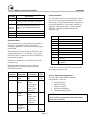
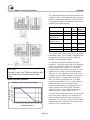
Internal Setpoint:
Item
The internal setpoint is set with parameter 4. The
boiler temperature control modulates the boiler to
maintain this internal setpoint. The upper and lower
temperature differentials are used to instruct the boiler
at what temperature to turn on and at what temperature
to turn off.
Item
Parameter
Value
Allowable
Range
Setpoint
4
160
68-185
Low Temp. Differential
22
10
0-36
High Temp. Differential
23
9
0-36
Low Temp. Setpoint
5
68
59-140
The boiler will modulate to try to maintain 160° F. If
the temperature increases above 169° F which is the
setpoint 160° F + High Temp Differential 9°F the
boiler will shut off. Once it shuts off it will not restart
until the temperature drops below 150° F which is the
setpoint – Low Temp Differential. The Low Temp Set
Point will not permit the operator to adjust the setpoint
below 68° F. (See graph below.)
Internal Setpoint
175
Boiler Turns Off
170
165
Boiler Temperature
160
Boiler Set Point
155
Boiler Turns On
150
145
0
10
20
30
40
Time
Domestic Priority:
If an indirect domestic hot water (DHW) tank is
connected, the DHW function of the boiler will
activate when the DHW temperature controller
(supplied by others) closes (Terminal 5 to 8 TB 1,
refer to Section 6.1.1), indicating a call for heat from
the DHW system. The parameters should be set as
follows:
Page 22
Parameter
Value
DHW Setpoint
1
140
DHW Setpoint Addition
33
30
DHW Status
2
1
DHW High Temp. Differential
25
6
DHW Low Temp. Differential
24
6
DHW Options
35
13
In the above example, the boiler temperature will be
set to the DHW Setpoint + the DHW Setpoint
Addition (140ºF + 30ºF = 170ºF) when the DHW
temperature controller indicates a call for heat from
the DHW system. When the DHW system calls for
heat, the Central heat pump output (Terminal 10
TB2) de-energizes and the DHW pump output
(Terminal 11 TB2) energizes providing 120 VAC
power is provided to energize a relay coil for the
DHW pump. The DHW status should be set to 1
(DHW system ON).
MACH® Series Gas-Fired Boiler
Installation
The control automatically detects the presence of the
outdoor air sensor. If an outdoor air sensor is present,
the boiler automatically defaults to outdoor air reset
for setting boiler temp. The parameters should be set
according to the following table:
Item
Parameter
Value
°F
Allowable
Range °F
Maximum Setpoint
4
180
68-185
Minimum Setpoint
5
80
60-140
Outdoor Air
Minimum Temp.
6
20
4-50
Outdoor Air
Maximum Temp.
7
70
59-77
Boiler Shutoff Temp.
10
90
32-140
(32=off)
Outdoor Air Offset
12
0
0-144
Boiler Configuration
34
01
The set point of the boiler is controlled by an outdoor
temperature sensor. As the outdoor temperature falls
the setpoint of the boiler is increased. The boiler
modulates to maintain this setpoint.
CAUTION!
Terminal 10 and 11 on TB2 are for pilot duty only.
they should not be connected directly to the
pump.
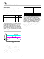
Outdoor Air Reset (optional):
BOILER SETPOINT °F
OU TD OO R A IR vs B OILER SETP O IN T
190
180
170
160
150
140
130
120
110
100
90
80
70
0
10
20
30
40
50
60
70
80
The setpoint is adjusted according to the above
parameters. The boiler setpoint will be the maximum
value (180° F) when the outdoor air is at or below a
minimum temperature value (20° F). The boiler
setpoint will be at the minimum value (80° F), when
outdoor air is at or above a maximum temperature
value (70° F). The setpoint for “in between“ values
of outdoor air temperature, is linearly proportional to
the above settings. Using the values in the table
above, the boiler setpoint will be 80° F when the
outdoor air temperature is 70° F. As the outdoor air
temperature drops, the boiler setpoint will be
increased until the outdoor air temperature is 20° F.
At this point the boiler will reach its maximum
setpoint of 180° F. If the outdoor air temp drops
further, the boiler setpoint remains at 180° F.
The boiler shutoff temperature can be used to turn the
boiler off at a given setpoint. For example if you
wanted to shut the boiler off when the outdoor air
temperature was above 65° F you would set the boiler
shutoff temp to 90° F since this is the setpoint that is
called for at 65° F outside air temp.
90
OUTDOOR AIR TEMP °F
Page 23
MACH® Series Gas-Fired Boiler
Installation
Analog Input to Control Firing Rate:
Analog Input to Adjust Setpoint:
Analog Input S etpoint
Analog Input Firing Rate
100
200
90
70
B oiler Setpoint
Non adjustable C urve
100
F iring R ate
B oiler Setpoint
80
150
60
50
40
30
20
50
10
0
0
0
0
1
2
3
4
5
6
7
8
9
1
2
3
4
5
6
7
8
9
10
10
V oltag e
V oltage
The control must be configured for analog input
direct drive by setting parameter 34 to 02.
The control must be configured for a remote analog
input setpoint according to the following table:
Item
Parameter
Value
°F
Allowable
Range °F
Maximum Setpoint
4
180
68-185
Minimum Setpoint
5
80
60-140
Boiler Configuration
34
03
The setpoint of the boiler is controlled by an external
0-10 VDC signal. A signal of at least 0.5 VDC is
required to start the boiler. At 0 VDC the setpoint is
32° F; at 10 VDC the setpoint is 212° F. This setpoint
is low and high limited by maximum and minimum
setpoint parameters. The controlled setpoint voltage
range narrows when these limits are used. If the above
tables values are used the boiler setpoint will be 80° F
when the voltage is anything less than approximately 3
VDC. It will then increase linearly with voltage until
approximately 8.5 VDC when it will be 180° F. The
setpoint will remain at 180° F even if voltage is
increased further.
Page 24
The firing rate of the boiler is controlled by an
external 0 to 10 VDC signal. At a voltage greater
than 0.5 VDC the boiler turns on and runs at low fire
until 1.8 VDC is reached. The firing rate increases
linearly with voltage until high fire is reached at 10
VDC. The boiler setpoint Parameter 4 remains active
to shut down the boiler when the temperature in the
boiler exceeds this value plus the high temp
differential. These voltage levels, as explained
above, are all “non-adjustable”.
3.12.2 Gas Pressure Adjustment
Note: Adjustments shall only be performed by
service representative specifically trained and
certified to perform maintenance on the
Patterson-Kelley MACH Series boiler.
See rating plate for the minimum and maximum gas
pressure of the boiler. Each boiler is furnished with a
manual shut-off valve which has an integrated test
port.
MACH® Series Gas-Fired Boiler
Installation
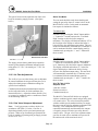
This port is located on the upstream side of the valve
body for measuring supply pressure. (See figure
below.)
Boiler Test Mode:
The test mode should be used when checking and
setting the gas safety shut off / control valves on the
MACH Series boilers. In this mode an automatic
heat request is simulated as follows:
Test Mode High:
Simultaneously pressing the “Mode” button and the
“+” button for 3 seconds activates the “Test Mode
High” function to drive the boiler output to
maximum. The display will blink and indicate “H” in
the first digit of the display to indicate the boiler is
being driven to the maximum output rating. This test
mode will automatically terminate after 15 minutes or
can be terminated from the control/display panel by
simultaneously pressing the “+” and “-“ buttons for
three seconds.
Test Port
Gas Pressure Test Port
The supply pressure during main burner operation
must be greater than the minimum indicated on the
rating plate (3.5". W.C. for natural gas, 7" W.C. for
propane).
3.12.3 Air Flow Adjustments
The air flow is pre-set at the factory prior to shipment.
In unusual situations the air/gas ratio may have to be
adjusted to obtain proper combustion readings for
specific local conditions.
Combustion measurement instrumentation must be
used to adjust the boiler for local conditions (See
instructions below). Adjust the carbon dioxide (CO2)
or oxygen (O2) reading to achieve conditions as listed
in the following Table 3-1.
3.12.4 Gas Valve Setup and Adjustment
Note: Verify gas pressure at inlet to boiler is in
accordance with Table 3-1 below. Gas flow is
dependent primarily on fan speed not upstream gas
pressure. When set up for natural gas operation, the
boiler is capable of operating with gas supply pressure
as low as 3.5” W C.
Page 25
Test Mode Low:
Simultaneously pressing the “Mode” button and the
“-” button for 3 seconds activates the “Test Mode
Low” function to drive the boiler output to minimum.
The display will blink and indicate “L” in the first
digit of the display to indicate the boiler is being
driven to the minimum output rating. This test mode
will automatically terminate after 15 minutes or can
be terminated from the control/display panel by
simultaneously pressing the “+” and “-“ buttons for
three seconds.
MACH C300 & C450
Required Tools:
2 mm hex wrench
Slotted screwdriver
Combustion analyzer
The MACH C300 and C450 boilers are equipped
with two combined gas/air control and gas safety shut
off control valves. The valves function in parallel
with the variable speed combustion blower to supply
the correct gas air ratio for optimum performance and
efficiency. The combustion blower speed is
controlled automatically and determines the amount
of negative pressure felt at the gas safety shut off /
control valves. The gas valve servo regulators adjust
gas flow for each valve to maintain zero pressure at
the outlet nozzle of the associated valves.
MACH® Series Gas-Fired Boiler
Installation
Table 3-1 Combustion Reading For Setting Gas Safety Shut Off / Control Valves
Nominal
High Fire Setting
Low Fire Setting
Fuel
Gas Pressure
% O2
% CO2
% O2
% CO2
Natural Gas
7" W.C
5.0 + 0.2
9.0 + 0.2
5.2 + 0.2
8.8 + 0.2
Propane
11" W.C
5.0 + 0.2
10.4 + 0.3
5.2 + 0.2
10.3 + 0.3
Adjustment:
There must be sufficient load to operate the boiler at
high fire to perform the following adjustments. Start
the boiler and observe proper operating parameters for
the system.
Note: The MACH C300 and C450 boilers are each
equipped with two gas safety shut off / control valves
that operate in parallel. When making any adjustment
to the valves, the adjustment must be performed on
each of the valves equally.
Example: If an increase in the gas flow is required to
lower the O2 level, turn each of the maximum flow
restrictors equivalent amounts (i.e. ¼ or ½ turn each)
and allow the analyzer readings to respond and
stabilize before proceeding with additional adjustment.
Adequate response time must be allowed for
combustion readings to stabilize. This response time
will be longer for low firing rates than for high firing
rates.
Clockwise rotation decreases gas flow.
Counterclockwise rotation increases gas flow.
Low Fire Setting
Set boiler to the “Test Mode Low”, as described
above, to achieve minimum firing rate of the boiler.
Check combustion readings using a combustion
analyzer. If combustion readings are not in
accordance with Table 3-1 adjust as follows:
Using a 2 mm hex wrench, adjust the pressure
regulator offset adjustment (see the figure below, item
“R”) to achieve the CO2 /O2 level prescribed in Table
3-1. Note that equal adjustments must be made to
each of the valves. Adjustments to the offset pressure
regulators should not exceed ¼ turn at a time before
allowing the readings to respond and stabilize. Please
note, the rotation of the Low Fire adjustment is
opposite of the High Fire as follows: Clockwise
rotation increases gas flow, counterclockwise rotation
decreases gas flow.
"R"
High Fire Setting
Set boiler to the “Test Mode High”, as described
above, to achieve maximum firing rate of the boiler.
Check combustion readings using a combustion
analyzer. If combustion readings are not in
accordance with Table 3-1 adjust as follows:
Using a slotted screw driver or 2 mm hex wrench, set
the maximum restrictor (high fire screw – see the
figure below, item “D”) on each of the gas safety shut
off / control valves by turning clockwise or
counterclockwise to achieve the desired CO2 or O2
level; see Table 3-1 for correct settings. (There will be
a slight time delay between the adjustment and the
response of the CO2/O2 measuring instrument).
Page 26
"D"
C300/450 Adjusting Low and High Fire
MACH® Series Gas-Fired Boiler
Installation
Low Fire Setting
MACH C750, C900 & C450
Required Tools:
Set boiler to the “Test Mode Low”, as described
above, to achieve minimum firing rate of the boiler.
Check combustion readings using a combustion
analyzer. If combustion readings are not in
accordance with Table 3-1, adjust as follows:
TORX® T40 or 5 mm hex wrench
3 mm or 7/64 in hex wrench
Combustion analyzer
The MACH C750,C900 and C1050 boilers are
equipped with a Honeywell combined gas/air control
and gas safety shut off control valves. The valve
functions in parallel with the variable speed
combustion blower to supply the correct gas air ratio
for optimum performance and efficiency. The
combustion blower speed is controlled automatically
and determines the amount of negative pressure felt at
the gas safety shut off / control valves. The gas/air
regulator adjusts gas flow to maintain the proper
pressure at the outlet nozzle of the associated valve.
Adjustment:
There must be sufficient load to operate the boiler at
high fire to perform the following adjustments. Start
the boiler and observe proper operating parameters for
the system.
High Fire Setting
Remove the cap on the gas regulator using a slotted
screwdriver (See Fig. XX). This will expose the offset
adjustment screw.
Using a TORX® T40 or a 5 mm hex wrench, carefully
adjust the low fire gas setting to achieve the CO2 /O2
level prescribed in Table 3-1.
Note: The rotation of the Low Fire adjustment is
opposite of the High Fire as follows: Clockwise
rotation increases gas flow, counterclockwise rotation
decreases gas flow.
Adjustments to the offset pressure regulators should
not exceed ¼ turn at a time before allowing the
readings to respond and stabilize.
After proper low fire offset adjustment is made,
reinstall the slotted cap on the regulator.
Following all gas valve adjustments, check for proper
light-off and verify correct fuel/air mix and
combustion quality throughout the entire firing range
(from lowest to highest fan speed).
High fire adjustment
Set boiler to the “Test Mode High”, as described
above, to achieve maximum firing rate of the boiler.
Check combustion readings using a combustion
analyzer. If combustion readings are not in
accordance with Table 3-1, adjust as follows:
Remove the flat, round, blue plastic cap from the
cover. Using a 3mm (7/64”) hex wrench, turn the
adjustment screw counterclockwise to increase or
clockwise to decrease gas flow and achieve the desired
CO2 or O2 level; see Table 3-1 for correct settings.
(There will be a slight time delay between the
adjustment and the response of the CO2/O2 measuring
instrument. Adjust the settings in small increments and
allow the combustion readings to stabilize before
readjusting. When desired adjustments are complete,
reinstall the blue plastic cap on the cover.
Page 27
Low fire adjustment
C750/900/10500 Adjusting Low and High
MACH® Series Gas-Fired Boiler
Operation
4.0 OPERATION
4.2.1 Lighting Procedures
4.1 GENERAL
1. Close main gas valve.
2. Turn On-Off switch to "OFF" position.
4.1.1 Control Panel Front
3. Wait 5 minutes.
4. Open main gas valve.
5. Turn On-Off switch to "ON" position.
6. Push reset button on display panel if required.
7. Push reset on low gas pressure switch and high gas
pressure switch.
The controller will now complete the automatic firing
sequence.
Control Panel
Become familiar with the basic operation of the boiler.
The front of the control panel shows Operating
Instructions.
4.1.2 Tests
Safe lighting and other performance criteria were met
with the gas manifold and control assembly provided
on this boiler when the boiler underwent tests
specified in ANSI Z21.13/CSA 4.9, latest edition.
(See "Factory Firetest" label.)
4.2 NORMAL LIGHTING AND SHUT-DOWN
PROCEDURES
If a fault is indicated please refer to
Troubleshooting, Section 5.5, to determine the
cause of the fault prior to start up.
WARNING!
Do not use this boiler if any part has been under
water. Immediately call a qualified service
technician to inspect the boiler and to replace any
part of the control system and any gas control
which has been under water.
Page 28
4.2.2 Normal Shut Down Procedures
1. Close all manual gas valves.
2. Turn off electric power.
MACH® Series Gas-Fired Boiler
Operation
4.2.3 Emergency Shut-Off
The main gas cock should be closed immediately if an
emergency situation occurs.
Main Gas Cock
WARNING!
If overheating occurs or the gas supply
fails to shut off, do not turn off or
disconnect the electrical supply to the
pump. Instead, shut off the gas supply at a
location external to the boiler.
Emergency Shut-Off
4.3 TYPICAL BOILER OPERATING CONDITIONS
Model
Number
Input
Rating
(Btu/hr)
Natural Gas
LP Gas
Total
*(1030 Btu/cu. ft.)
**(2500 Btu/cu. ft.)
Amperage
Gas
Rate
(CFH)
Output
Capacity
(Btu/hr)
Gas
Rate
(CFH)
Output
Capacity
(Btu/hr)
300
300,000
291*
275,000
120**
275,000
8 amps or less
450
450,000
437*
414,000
180**
414,000
8 amps or less
750
750,000
728*
712,500
300*
712,500
8 amps or less
900
900,000
873*
846,000
360**
846,000
8 amps or less
1050
1,050,000
1019*
987,000
420**
987,000
8 amps or less
Note: The heat exchanger is constructed and stamped for 50 psig maximum operating pressure and/or 200º F
maximum temperature.
Page 29
MACH® Series Gas-Fired Boiler
Maintenance
5.0 MAINTENANCE
WARNING!
Check daily to be sure that the boiler area is free
and clear of any combustible materials, including
flammable vapors and liquids.
5.1 MAINTENANCE AND INSPECTION SCHEDULE
WARNING!
5.1.2 Weekly
Label all wires prior to disconnection when
servicing controls. Wiring errors can cause
improper and dangerous operation.
Observe the conditions of the main flame. A normal
high fire flame is blue. If the high fire flame is yellow
then corrective action must be taken. In normal low
fire the burner will glow a yellowish-orange.
WARNING!
Correct air adjustment is essential to the efficient
operation of this boiler. If an adjustment in the
combustion is necessary, the flue gas composition
should be checked with a carbon dioxide (CO2) or
oxygen (O2) analyzer to set conditions. Refer to Table
3-1, Section 3.12.4 for proper combustion readings.
Use care when reassembling main gas line to
assure all connections are tight.
WARNING!
Use care when servicing boiler in order to prevent
the accumulation of gas in or around the
combustion chamber.
5.1.3 Monthly (During Operation)
1. Test flame detection by voltage reading at the
terminal strip (Terminal 9 on TB-1 and ground
screw). The voltage reading should be between (5
and 10 VDC).
WARNING!
General lockout/ tagout procedure must be
employed when servicing this unit.
2. Test high-limit Control. Refer to Section 3.11.3.
WARNING!
Determine the cause of the lockout before
resetting the boiler. If able to determine cause of
lockout, then appropriate corrective action should
be taken. If not able to determine cause of the
problem, call a qualified service technician.
3. Test operating temperature controls by reducing or
increasing temperature setting as necessary to
check burner operation.
4. Test the low water level cut-out. Refer to Section
3.11.2.
5. Test low gas pressure switch. Refer to Section
3.11.4.
Verify proper operation after servicing.
6. Check the condensate drain system. Clean and
flush as necessary.
5.1.1 Daily
Installation and service must be performed by a
qualified installer or service agency who has been
trained on the Patterson-Kelley MACH boiler.
Observe operating temperature and general conditions.
Make sure that the flow of combustion and ventilating
air to the boiler is not obstructed. Determine the cause
of any service codes or lockouts on the display panel.
Observe any unusual noises or operating conditions
and make the necessary corrections. Notify
responsible individuals for required corrective action
or repair.
Page 30
MACH® Series Gas-Fired Boiler
Maintenance
5.1.4 Semi-Annually (every 6 months)
7. Qualified service personnel should thoroughly
inspect the heating system and correct any
problems prior to re-starting the boiler.
In addition to the recommended monthly service:
1. Clean burner of any accumulated dust or lint. See
Section 5.2 on "Cleaning the Burner."
2. Inspect burner for any signs of deterioration or
corrosion. Replace immediately if deterioration or
corrosion is evident.
Installation and service must be performed by a
qualified installer or service agency who has been
trained on the Patterson-Kelley MACH boiler.
The blower motor is permanently lubricated and does
not require periodic lubrication.
5.1.5 Annually
8. Perform combustion analysis and readjust to
manufacturer's specifications as necessary. It is
recommended that a copy of this report is filed for
future reference.
9. Perform a leak test of the gas valves in accordance
with the manufacturer's instructions.
Installation and service must be performed by a
qualified installer or service agency who has been
trained on the Patterson-Kelley MACH boiler.
5.2 CLEANING THE BURNER
In addition to the recommended monthly service:
1. Inspect and clean the inlet screen of any
accumulated dust or lint.
1. Lockout and tagout gas supply to the boiler.
2. Check burner and clean off any soot or foreign
material that may have accumulated. See Section
5.2 on "Cleaning the Burner." Check for corrosion
of the burner and its parts. If there is evidence of
deterioration or corrosion, replace immediately.
3. Remove the top cover of the boiler.
2. Lockout and tagout electrical power to the boiler.
3. Inspect combustion chamber when the burner is
removed for inspection. Note any signs of
deterioration. Clean as necessary.
4. Inspect and clean heat exchanger. Use vacuum to
remove accumulations from the heat exchanger
pins and surfaces. Clean the casting pins by
flushing with clean water and air drying. Do not
use any cleaning agents or solvents. A soft nylon
brush may be used in accessible areas.
5. Drain and flush the inside of the heat exchanger as
required (separate from system flush).
6. Examine the venting system at least once a year.
Refer to the vent manufacturer's instructions for
requirements in addition to those listed below.
4. Disconnect the electrical connections to the blower
and gas safety shut off / control valves.
5. Unbolt burner hood and remove the gas train
assembly.
6. Carefully remove the burner. Use low pressure air
to remove any dust or lint from the burner. Using
a soft clean cloth, wipe the inside surface of the
burner. DO NOT wipe the mesh side (flame side)
of the burner.
5.3 AFTER ALL REPAIRS OR MAINTENANCE
1. Follow "Pre-Start Check List" (Section 3.10) and
all "Safety Checks" (Section 3.11).
2. Check gas pressure. (Section 3.12.2.)
3. Perform combustion check. Adjust gas flow if
necessary. (Section 3.12.4.).
a. Check all joints and pipe connections for
tightness.
b. Check pipe for corrosion or deterioration. If
any piping needs replacing, do so
immediately.
Page 31
MACH® Series Gas-Fired Boiler
Maintenance
5.4 SEQUENCE OF OPERATION
1. When the On/Off (Main power) switch is turned
on, power is provided through a circuit breaker to
the boiler control and the combustion blower. The
boiler control powers a 24 V transformer. The
boiler control supplies 24 V power through a high
limit temperature switch and a low water level
control.
2. The low water level control is closed when there is
water in the boiler up to the probe.
3. When the temperature sensed by the high limit
temperature control is below the set limit, the
switch is closed. Manual reset of the switch is
required following conditions exceeding high limit
temperature.
4. If either the high limit temperature control or the
low water level control is open, the boiler control
locks out and indicates E 12 on the display.
5. Depending on the settings in the boiler control, a
heat request is generated.
6. The controller checks that the low air pressure
switch is open indicating no airflow. The blower
is driven towards the prestart fan speed. When the
air pressure switch closes the 15 second prepurge
time is started, and the blower is driven toward the
ignition speed.
7. After the 15 second prepurge the gas pressure
switch circuit is checked to ensure the gas pressure
is within design parameters.
8. If there are no lockouts then when the blower
speed is within 200 rpm of the ignition fan speed,
a trial for ignition period of 3 seconds is initiated.
The internal spark generator and the gas safety
shut off / control valves are energized.
9. The internal spark generator is de-energized .3
seconds before the end of the trial for ignition
period. After the trial for ignition period, if a flame
signal is detected by the flame rectification
system, the control initiates a flame stabilization
period of 5 seconds at the ignition rpm of the fan.
The fan is driven to low fire for 1 minute before
the boiler is released to modulation.
Page 32
10. The unit modulates between the low fire setting
and the high fire setting to maintain the desired
outlet water temp set point.
11. When the load is below the low fire rating of the
boiler the boiler will continue firing and the outlet
water temperature will rise until it reaches the set
point + temperature differential. At this point the
burner is turned off, and the fan continues to run to
post purge the boiler for 15 seconds.
12. When the water temperature is reduced by the load
on the system, a heat request is again generated.
The operating sequence will recycle to step 6,
provided the limits on water level, gas pressure
and high temperature are all met.
5.5 TROUBLESHOOTING
The MACH Series boiler will display service codes to
indicate some problems with the boiler. There are two
types of lockouts the control may experience: manual
reset lockouts requiring an operator to press the reset
button, and automatic reset lockouts, where the control
will automatically attempt to restart the boiler. A
listing of service codes is included at the end of this
section.
Should the unit fail to operate, call a qualified service
technician to troubleshoot the problem and implement
corrective action.
The Loss of Power
In the event of a power failure (or when the On/Off
switch is in the Off position), the display panel is not
illuminated and the entire system is de-energized,
closing all automatic valves and halting all boiler
operations. When power is restored the sequence of
operation will resume at Step 5, provided that all the
limits are satisfied. If any manual reset lockout was
present when the power is lost, the display will flash E
04 when the power is resumed. This indicates that the
control was in lockout mode but does not indicate
which service code was present.
MACH® Series Gas-Fired Boiler
Maintenance
Loss of Water Level
The low water switch opens when there is insufficient
water level in the boiler. E 12 is shown on the display,
and burner operation is interrupted. When the correct
water level is re-established, pushing the reset button
will return the sequence to Step 5, provided that the
other limits are satisfied.
Low Gas Pressure
The low gas pressure switch opens when there is (or
has been) insufficient gas pressure available for proper
operation of the boiler; E 12 is shown on the display,
and burner operation is interrupted. If a gas-supply
shut-off valve is closed for any reason, a low gas
condition will result.
When gas pressure is restored, E 12 will remain on the
display panel, and the boiler will remain locked out
until the front panel reset button is pressed.
Once the control is reset, the sequence returns to Step
5, provided that the other limits are satisfied.
manually reset and the front panel reset button is
pressed. Once the switch, and the front panel are reset,
the sequence returns to Step 5, provided that the other
limits are satisfied.
Low Air
If the display panel indicates E 08 this indicates
insufficient airflow through the burner. Check that the
burner is clean ("Cleaning the Burner," Section 5.2)
and that there are no obstructions to airflow in the
intake or exhaust ducts. A low air indication does not
necessarily mean that the low air switch is defective.
Air Switch Closed
If the display panel indicates B 61 this indicates the air
pressure switch did not open when the blower was shut
off. Check that there is no air flow through the boiler
when the fan is off. If there is no hidden source of air
flow, replace the switch.
Flame Failure
High Gas Pressure
The high gas pressure switch opens when there is (or
has been) excessive gas pressure for the proper
operation of the boiler. An E 12 service code is
displayed and the burner operation is interrupted.
When proper gas pressure is restored, E 12 remains on
the display with the boiler locked out until the front
display panel reset button is pressed.
High Water Temperature
When the boiler water has exceeded both the operating
and high-limit temperature the high limit switch opens,
and E 12 is shown on the display. When the water
temperature falls below the high-limit temperature, the
boiler will remain locked out until the switch is
Page 33
In the event of a flame failure during a firing period or
a trial for ignition, the main fuel valves are deenergized and a manual reset lockout occurs. After the
spark ignition is re-energized, the 3 second trial-forignition begins again. If flame failure occurs during a
trail-for-ignition, a safety lockout occurs. The display
will indicate E 02. If flame failure occurs and an
service code is displayed, the combustion control must
be manually reset.
E 00 signifies a leaky gas valve. In the event of a false
flame signal E 00 fault code is indicated. This fault
code could indicate a gas valve failure or leakage of
the gas valve. If gas valve leakage is suspected, the
unit must be isolated by turning off the main gas
supply line until the gas valve is replaced.
MACH® Series Gas-Fired Boiler
Maintenance
5.5.1 Manual Reset Service Codes
Code
Lockout
Description
E 00
False flame.
A flame signal is present when it shouldn’t be.
E 02
Flame failure.
The burner did not light on startup, or loss of flame during run.
E 03
Gas Valve error.
Check all gas valves electrical connections.
E 04
General lockout.
The power was lost after a lockout. The control loses the description of the lockout on
power loss.
E 05
Internal control failure.
Call for service.
E 06
Internal control failure.
Call for service.
E 07
Internal control failure.
Call for service.
E 08
Air pressure switch open.
The air pressure switch failed to close to indicate sufficient air flow to start the boiler.
E 11
Internal control failure.
Call for service.
E 12
External limit open.
One of the external limits has opened. (High/Low Gas Pressure, High Temp, Low water).
E 13
Internal control failure.
Call for service.
E 14
Internal control failure.
Call for service.
E 15
Internal control failure.
Call for service.
E 16
Internal control failure.
Call for service.
E 17
Internal control failure.
Call for service.
E 18
Outlet high limit temp.
The outlet water temperature has exceeded the internal high limit temperature setting.
E 19
Return high limit temp.
The return water temperature has exceeded the internal high limit temperature setting.
E 25
Outlet temp rapid change.
The outlet water temperature is increasing too fast. Indicating low flow condition.
E 28
No blower feedback.
The blower should be running but it is not, or the feedback signal has been interrupted.
E 29
Blower feedback will not zero. The blower will not go to zero speed even though it should be off.
E 31
Outlet sensor shorted.
The outlet temperature sensor is short circuited.
E 32
Return sensor shorted.
The return temperature sensor is short circuited.
E 33
DHW sensor shorted.
The DHW temperature sensor is short circuited.
E 35
Flue sensor shorted.
The flue gas temperature sensor is short circuited.
E 36
Outlet sensor open.
The outlet temperature sensor is indicating an open circuit.
E 37
Return sensor open.
The return temperature sensor is indicating an open circuit.
E 38
DHW sensor open.
The DHW sensor is indicating an open circuit.
E 40
Flue sensor open.
The flue gas temperature sensor is indicating an open circuit.
E 44
Internal control failure.
Call for service.
E 52
High flue temp.
The flue temperature has exceeded the maximum allowable setting.
E 60
Internal control failure.
Call for service.
Note: When an Internal Control Failure occurs, as identified by E-Codes listed above, the failure is internal to the
MCBA and replacement of the MCBA is required. A qualified service technician must be called to replace the
MCBA device.
Page 34
MACH® Series Gas-Fired Boiler
Maintenance
5.5.2 Auto-reset Service Codes
Code
Lockout
Description
b 08
Air pressure switch open.
The air pressure switch failed to close to indicate sufficient air flow to start the boiler.
b 18
Outlet high limit temp.
The outlet water temperature has exceeded the internal high limit temperature setting.
b 19
Return high limit temp.
The return water temperature has exceeded the internal high limit temperature setting.
b 24
Switched inlet / outlet.
The inlet water temperature has been more than 18° F above the outlet for more than
75 seconds.
b 25
Outlet temp rapid change.
The outlet water temperature is increasing too fast. Indicating low flow condition.
b 26
High exhaust back pressure.
The high exhaust back pressure switch is tripped indicating a blocked stack, inlet, or
condensate system.
b 30
Max delta T.
The temperature rise across the heat exchanger is greater than maximum allowed,
indicating insufficient flow.
b 40
Flue sensor open.
The flue gas temperature sensor is indicating an open circuit.
b 52
High flue temp.
The flue temperature has exceeded the maximum allowable setting.
b 61
Air pressure switch closed.
The air pressure switch failed to open prior to starting the blower.
b 65
Fan speed incorrect.
The fan is being directed to a higher speed than it is achieving.
WARNING
If any “Manual Reset” limit device trips,
DO NOT
reset without determining and correcting the cause.
Page 35
MACH® Series Gas-Fired Boiler
Parts and Technical Support
6.0 PARTS/TECHNICAL SUPPORT
Spare parts and replacement parts can be ordered from
Patterson-Kelley by calling toll free (877) 728-5351.
Ask for the Heat Transfer Department. The fax
number is (570) 476-7247. Refer to the parts list
shown on the assembly drawing provided with this
manual. Technical information is also available at the
above number. When ordering replacement parts
please have the model number and serial number of
your boiler available.
Page 36
MACH® Series Gas-Fired Boiler
Parts and Technical Support
6.1 WIRING DIAGRAMS
6.1.1 Terminal Block Assignments – High Voltage Circuit (TB2)
Terminal Number
Label
Description
1
115 VAC LINE
Boiler Supply Power, 115 VAC, 60 HZ, 1 ph, 8 amp
2
115 VAC NEUTRAL
3
115 VAC NEUTRAL
Aux. Switched Output
4
115 VAC NEUTRAL
Boiler Circ. Pump
5
115 VAC NEUTRAL
DHW Circ. Pump
6
GROUND
Boiler Supply Ground
7
GROUND
Aux .Ground
8
GROUND
9
115 VAC SW. OUTPUT
Aux. Switched Output, Pilot duty only, 1 amp max.
10
115 VAC CIRC. PMP
CONTACTOR
Boiler Circ. Pump, Pilot duty only, 1 amp max.
11
115 VAC DHW PMP
CONTACTOR
DHW Circ. Pump, Pilot Duty only, 1 amp max.
12
MASTER ALARM RELAY
Dry Contacts, 24 VAC max, 1 amp max.
13
MASTER ALARM RELAY
14
THREE WAY VALVE RELAY
15
THREE WAY VALVE RELAY
16
DAMPER RELAY
17
DAMPER RELAY
DHW Dry Contacts, 24 VAC max, 1 amp max.
Combustion Air Damper, Dry Contacts, 24 VAC max, 1 amp
max.
Page 37
MACH® Series Gas-Fired Boiler
Parts and Technical Support
6.1.1a Terminal Block Assignments – Low Voltage Circuit (TB1)
Terminal Number
Label
Description
1
HEAT REQUEST
2
HEAT REQUEST
3
INTERLOCK JUMPER
4
INTERLOCK JUMPER
5
DHW TEMP. SENSOR
6
OUTDOOR TEMP SENSOR
Thermistor - factory option.
7
CIRC. PMP PWM SIGNAL
Pulse Width Modulation.
8
COMMON
Common to be used with 5, 6, 7, and 10 when used.
9
COMMON
Common to be used with 5, 6, 7, and 10 when used.
10
O-10 V ANAL. INPUT CONTROL Remote control of firing rate or setpoint.
11
+10 VOLT
Regulated 10V output.
12
COM 1
RS-485 port A.
13
COM 2
RS-485 port B.
14
OUTSIDE TEMP W/ FILTER
Thermistor - factory option.
15
OUTSIDE TEMP W/ FILTER
Thermistor - factory option.
16
SPARE
17
SPARE
Boiler Enable, Contact Closure.
DO NOT ENERGIZE.
External Limit (auto reset), Contact Closure.
DO NOT ENERGIZE.
Page 38
MACH® Series Gas-Fired Boiler
Parts and Technical Support
6.1.2 Wiring Series C-300
Page 39
MACH® Series Gas-Fired Boiler
Parts and Technical Support
6.1.3 Wiring Series C-450
Page 40
MACH® Series Gas-Fired Boiler
Parts and Technical Support
6.1.4 Wiring Series C-750/900/1050
Page 41
MACH® Series Gas-Fired Boiler
Parts and Technical Support
6.2 BOILER PARTS LIST
6.2.1 Main Assembly
MACH Series 300/450
Mark
MACH Series 750/900/1050
Description
1
Blower and Gas Train
2
Manifold, System Return, Boiler Outlet
3
Manifold, System Supply, Boiler Inlet
4
Cabinet
5
High Temperature - Aquastat
Mark
1
2
3
4
Page 42
Description
Heat Engine
Boiler Gas Train
Cabinet
Control Panel
MACH® Series Gas-Fired Boiler
Parts and Technical Support
6.2.2 Control Panel
Mark
Description
1
AM-3 Relay Module
2
Boiler Control MACH Series - MCBA
3
Transformer
4
Low Water Cutoff
5
Control Mounting Plate
Page 43
MACH® Series Gas-Fired Boiler
Parts and Technical Support
6.2.3 Display Panel
3
2
Mark
Description
1
Circuit Breaker
2
Air Pressure Switch
3
Fastening Clip
4
Display Panel
5
On/Off Switch
6
Pressure Temperature Gauge
7
Panel Sheet Metal
8
Stack Pressure Switch
4
8
7
1
6
5
Page 44
MACH® Series Gas-Fired Boiler
Parts and Technical Support
6.2.4 C-300/450 Heat Engine
Mark
Description
1
Gasket Blower to Burner Hood
2
Burner Hood
3
Inside Burner Hood Gasket
4
Outside Burner Hood Gasket
5
Burner
6
Burner Flange With Insulation
7
Sight Glass
8
Seal Sight Glass
9
Sight Glass Holder
10
Exhaust Pipe Lip Ring
11
Exhaust Manifold
12
Inspection Cover Gasket
13
Inspection Cover
14
Gasket (Header Gasket)
15
Boiler Outlet / Supply Manifold
16
Boiler Inlet / Return Manifold
17
Condensate Trap
18
Manifold Mounting Plate
19
Thermistor (Temperature Sensor)
Page 45
MACH® Series Gas-Fired Boiler
Parts and Technical Support
6.2.5 C-750/900/1050 Heat Engine
MARK
1
2
3
4
5
6
7
8
9
10
11
12
13
14
DESCRIPTION
Gasket Blower to Burner Hood
Burner Hood
Burner Hood Gasket
Burner
View Glass Assembly
Heat Exchanger Sectional Castings
Exhaust Pipe Lip Ring
Condense Collector / Exhaust Manifold
Inspection Cover & Gasket
Manifold Gaskets
Boiler Outlet / Supply Manifold
Boiler Inlet / Return Manifold
Condensate Trap
Manifold Mounting Plate
Page 46
MACH® Series Gas-Fired Boiler
Parts and Technical Support
6.2.6 C-300 Boiler Gas Train
Mark
Description
1
Main Gas Shut-off Valve
2
Low Gas Pressure Switch
3
Gas Safety Shut-off/Control Valve
4
Air/Gas Manifold
5
Swirlplate
6
Blower
7
Gas Leak Test Port
8
Flex Hoses w/ Gas Valve Adaptors
Page 47
MACH® Series Gas-Fired Boiler
Parts and Technical Support
6.2.7 C-450 Boiler Gas Train
Mark
Description
1
Main Gas Shut-off Valve
2
Low Gas Pressure Switch
3
High Gas Pressure Switch
4
Gas Safety Shut-off/Control Valve
5
Gas Manifold Shut-off Valve
6
Air/Gas Manifold
7
Swirlplate
8
Blower
9
Gas Leak Test Port
10
Flex Hoses with Gas Valve Adapters
Page 48
MACH® Series Gas-Fired Boiler
Parts and Technical Support
6.2.8 C-750/900/1050 Boiler Gas Train
Mark
Description
1
Main Gas Shut-off Valve
2
Low Gas Pressure Switch
3
High Gas Pressure Switch
4
Gas Safety Shut-off/Control Valve
5
Gas Manifold Shut-off Valve
6
Flex Hose with Gas Valve Adaptor
7
Venturi
8
Premix Combustion Blower
9
Burner Hood
10
Burner
Page 49
MACH® Series Gas-Fired Boiler
Limited Warranty
7.0 LIMITED WARRANTY
Subject to the terms and conditions herein and except
as provided below with respect to products or parts not
manufactured by Patterson-Kelley Co., Seller warrants
to the original owner at the original installation site
that products manufactured by Seller ("Products") will
be free from defects in materials and workmanship for
a period of five (5) years from date of shipment (the
"Warranty Period"). For products or parts not
manufactured by Patterson-Kelley, the warranty
obligations shall, in all respects, be limited to one (1)
year.
C. Any damage to the Product due to abrasion,
erosion, corrosion, deterioration, abnormal
temperatures or the influence of foreign matter or
energy.
D. The design or operation of owner's plant or
equipment or of any facility or system of which
any Product may be made a part.
E. The suitability of any Product for any particular
application.
F. Any failure resulting from misuse, modification
not authorized by Seller in writing, improper
installation or lack of or improper maintenance.
G. Equipment furnished by the owner, either mounted
or unmounted, or when contracted for by the
owner to be installed or handled.
REMEDY
The sole remedy of this warranty is expressly limited
to the repair or replacement of any part found to be
defective under conditions of normal use within the
Warranty Period. Installation is not included.
H. Leakage or other malfunction caused by:
1. Defective installations in general and
specifically, any installation which is made:
a. in violation of applicable state or local
plumbing housing or building codes,
WARRANTY
b. contrary to the written instructions
furnished with the unit
The owner must notify the original installer of the
Product and Seller (Attention: Patterson-Kelley Co.,
P.O. Box 458, East Stroudsburg, PA 18301), in
writing, within the Warranty Period, providing a
detailed description of all claimed defects.
Transportation to the factory or other designated
facility for repairs of any products or items alleged
defective shall, in all events, be the responsibility and
at the cost of the owner.
2. Adverse local conditions in general and,
specifically, sediment or lime precipitation in
the tubes and/or headers or corrosive elements
in the atmosphere.
3. Misuse in general and, specifically, operation
and maintenance contrary to the written
instructions furnished with the unit,
disconnection, alteration or addition of
components or apparatus, not approved by
Seller, operation with fuels or settings other
than those set forth on the rating plate or
accidental or exterior damage.
EXCLUSIONS
Seller shall have no liability for and this warranty does
not cover:
A. Incidental, special or consequential damages, such
as loss of the use of products, facilities or
production, inconvenience, loss of time or labor
expense involved in repairing or replacing the
alleged defective Product.
B. The performance of any Product under conditions
varying materially from those under which such
Product is usually tested under industry standards
at of the time of shipment.
Page 50
I.
Production of noise, odors, discoloration or rusty
water.
J.
Damage to surrounding area or property caused by
leakage or malfunction.
K. Costs associated with the replacement and/or
repair of the unit including: any freight, shipping
or delivery charges, any removal, installation or
reinstallation charges, any material and/or permits
required for installation, reinstallation or repair,
MACH® Series Gas-Fired Boiler
Limited Warranty
SEVERABILITY
charges to return the boiler and or components.
Seller's liability under this warranty shall not in
any case exceed the amount paid for the Product
found to be defective.
To the extent that any provision of this warranty would
be void or prohibited under applicable law, such
provisions shall be limited in effect to the minimum
extent necessary to render the remaining provisions
hereof enforceable.
THIRD PARTY WARRANTIES
For goods or components not manufactured by Seller,
the warranty obligations of Seller shall, in all respects,
conform and be limited to one (1) year from the date
of shipment.
Page 51
NO OTHER WARRANTIES
Seller makes no implied warranty of merchantability
or fitness for a particular purpose or other warranties
with respect to any products or services except as
expressly set forth in this limited warranty.
MACH® Series Gas-Fired Boiler
Appendix
8.0 APPENDIX
Date
Hi/Low-Fire
O2
CO
CO2
Page 52
Stack Temp
Action
By
Outdoor Air Offset
Maximum fanspeed CH (hundreds)
Maximum fanspeed CH (units)
Maximum fanspeed DHW (hundreds)
Maximum fanspeed DHW (units)
Minimum fanspeed (hundreds)
Minimum fanspeed (units)
Ignition fanspeed (hundreds)
Postpumptime CH
Postpumptime DHW
CH modulation hysteresis On
CH modulation hysteresis Off
DHW modulation hysteresis On
DHW modulation hysteresis Off
DHW detection hysteresis On
12
13
14
15
16
17
18
19
20
21
22
23
24
25
26
11 Booster time
4 Setpoint or Maximum Setpoint (OAR)
Service Settings
5 Minimum Setpoint, Outdoor Air Reset (OAR)
6 Minimum outdoor temp (OAR)
7 Maximum outdoor temp (OAR)
8 Frost protection, at OA Temp
9 Correction, Outdoor Air Sensor
10 CH shutdown setpoint temp (OAR)
3 CH system
End User Settings
1 Setvalue for DHW
2 DHW system
Parameter Settings for MCBA Controls
No. Description
Parameter Settings for MCBA Controls
60 F
-4 F
59 F
-22 F
-9 F
32 = off
34 F
0 = no booster
1 minute
0F
10
00
10
00
5
00
5
0 = 10 Seconds
1 Minute
0 Seconds
0F
0F
-9 F
-9 F
-9 F
Water Storage Tank: 68 F
0 = off
1 = on
2 = off+ pump continuous
3 = on+ pump continuous
0 = off
1 = on
2 = off+ pump continuous
3 = on+ pump continuous
68 F
Lower Limit
32
0
140 F
99 Minutes
30 x 10.2 seconds
36 F
18 F
54 F
54 F
54 F
3
10
10
10
10
5
0
60
00
60
00
16
00
35
1
80
20
70
32
0
30 minutes
144 F
70
99
70
99
70
99
70
1
3
10
10
10
10
5
0
57
00
57
00
20
00
35
1
32
0
80
20
70
32
0
180 180
1
1
1
1
1
1
1
1
MACH
1050 PK
Factory
Setting
for MCBA
NG LPG
140 140
0
0
3
10
10
10
10
5
0
56
00
56
00
12
00
25
1
32
0
80
20
70
32
0
3
10
10
10
10
5
0
54
00
54
00
20
00
25
1
32
0
80
20
70
32
0
3
10
10
10
10
5
0
49
00
49
00
11
50
22
1
32
0
80
20
70
32
0
3
10
10
10
10
5
0
48
50
48
50
13
00
22
1
32
0
80
20
70
32
0
3
10
10
10
10
5
0
56
00
56
00
13
00
22
1
32
0
80
20
70
32
0
3
10
10
10
10
5
0
54
00
54
00
13
00
22
1
32
0
80
20
70
32
0
3
10
10
10
10
5
0
60
00
60
00
13
00
22
1
32
0
80
20
70
32
0
3
10
10
10
10
5
0
58
00
58
00
13
00
22
1
32
0
80
20
70
32
0
180 180 180 180 180 180 180 180
1
MACH
MACH
MACH
MACH
900 PK
750 PK
450 PK
300 PK
Factory Factory Factory Factory
Setting
Setting
Setting
Setting
for MCBA for MCBA for MCBA for MCBA
NG LPG NG LPG NG LPG NG LPG
140 140 140 140 140 140 140 140
0
0
0
0
0
0
0
0
140 F
50 F
77 F
50 F
9F
182
Water Storage Tank: 158 F
Upper Limit
Installed
MCBA
Parameter
Settings
Difference T1-T2 for modulating back
RMCI address
Setvalue addition for DHW, Parameter 1
CH Heat Request Type
(1st digit) 2nd CH-circuit
31
32
33
34
DHW: 3 Way Valve or Pump (1st digit)
35 DHW
Type (2nd digit)
(2nd digit) CH Heat Request Type
54 F
30 x 10.2 seconds
30 x 10.2 seconds
-36 F
0 seconds
0 seconds
0 = switch with burner On
1 x 10.2 seconds
9F
-1 = RMCI Off
0F
DHW detection hysteresis Off
Restart delay CH x 10.2 seconds
Restart delay DHW x 10.2 seconds
Restart delay DHW to CH
27
28
29
30
X0 = Instant water heater with NTC3
X1 = Instant water heater without NTC3
X2 = Storage tank with NTC3
X3 = Storage tank without NTC3
X4 = Instant water heater+NTC3+anticondensation
X5 = Instant water heater +anticondensation
X6 = Storage tank+NTC3+anticondensation
X7 = Storage tank+anticondensation
X8 = Plate heat exchanger
X9 = External heat request (by RMCI )
0X = 3 way valve normally open
1X = Hot water pump
0X = 2nd CH-circuit off
1X = 2nd CH-circuit slave
2X = 2nd CH-circuit master
3X = 2nd CH slave, Tset depends on potmeter
4X = 2nd CH master, Tset depends on potmeter
5X = 2nd CH- circuit slave,during DHW
6X = 2nd CH- circuit master, during DHW
7X = 2nd CH slave, during DHW,Tset depends on potmeter
8X = 2nd CH master, during DHW,Tset depends on potmeter
X0 = Room Thermostat
X1 = Outside Temperature
X2 = 0 - 10 V on MCBA: Capacity
X3 = 0 - 10 V on MCBA: Temperature
X4 = 0 - 10 V on AM4: Capacity
X5 = 0 - 10 V on AM4: Temperature
X6 = +/- Control
(194- par 1) F or 54 F
30 x 10.2 seconds
72 F
Upper Limit
Lower Limit
No. Description
Parameter Settings for MCBA Controls
13
13
X
X
X
X
X
X
46
-1
30
00
X
46
-1
30
00
X
X
X
13
X
46
-1
30
00
X
X
X
13
X
46
-1
30
00
X
X
X
13
X
46
-1
30
00
X
X
X
13
X
46
-1
30
00
X
X
X
13
X
46
-1
30
00
X
X
X
13
X
46
-1
30
00
X
X
X
13
X
46
-1
30
00
X
X
X
13
X
46
-1
30
00
X
MACH
MACH
MACH
MACH
MACH
900 PK 1050 PK
750 PK
450 PK
300 PK
Factory Factory Factory Factory Factory
Setting
Setting
Setting
Setting
Setting
for MCBA for MCBA for MCBA for MCBA for MCBA
5
5
5
5
5
5
5
5
5
5
3
3
3
3
3
3
3
3
3
3
3
3
3
3
3
3
3
3
3
3
3
3
3
3
3
3
3
3
3
3
Installed
MCBA
Parameter
Settings
39
40
41
42
Special pump CH / DHW
Max Setpoint, 2nd CH-circuit
Min Setpoint, 2nd CH-circuit
Hysteresis 2nd CH-circuit
Low/off Cycle
36 Manual fanspeed
37 PWM-level CH-pump:
38 Hold boiler water DHW only
No. Description
Parameter Settings for MCBA Controls
Upper Limit
X0 = Off
X1 = On
0X = CH: normal pump function
DHW: normal pump function
1X = CH: pump off
DHW:normal pump function
2X = CH: normal pump function
DHW: 5 second pump delay
3X = CH: pump off
DHW: 5 second pump delay
32 = off
34 F
50 F
50 F
34 F
176 F
176 F
140 F
86 F
2X = 3 way valve normally closed
-1 = off
Lower Limit
-1
41
X
X
32 32
100 100
50 50
14 14
00 00
X
X
-1
41
-1
41
-1
41
-1
41
-1
41
-1
41
-1
41
-1
41
X
X
X
X
X
X
X
X
32 32 32 32 32 32 32 32
100 100 100 100 100 100 100 100
50 50 50 50 50 50 50 50
14 14 14 14 14 14 14 14
00 00 00 00 00 00 00 00
X
X
X
X
X
X
X
X
-1
41
MACH
MACH
MACH
MACH
MACH
900 PK 1050 PK
750 PK
450 PK
300 PK
Factory Factory Factory Factory Factory
Setting
Setting
Setting
Setting
Setting
for MCBA for MCBA for MCBA for MCBA for MCBA
Installed
MCBA
Parameter
Settings