1
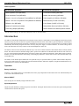
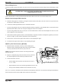
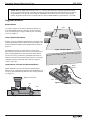
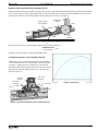
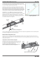
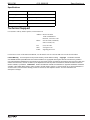
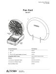
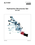
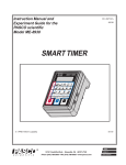
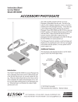
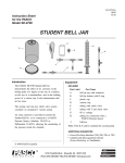
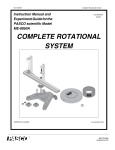
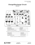
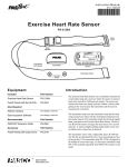
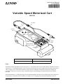
Instruction Manual 012-06880B ® *012-06880* Variable Speed Motorized Cart ME-9781 1.8 m Cable 3.5 mm Plug Accessory Tray Threaded 1/4-20 Hole Threaded Holes for ME-9496 Hole Time Pulse Accessory Banana Plugs Threaded Hole ON/OFF Switch External Input Port (Maximum; ± 6 VDC) Speed Control Knob Included Items Included Items Variable Speed Motorized Cart 1.8 m Cable Assembly, 3.5 mm plug Power The PASCO Variable Speed Motorized Cart can use four “C” cells (batteries) that are not included. NOTE: The PASCO PI-6603 is a four pack of “C” sized alkaline batteries. The cart can also be powered by a DC power supply (such as the PASCO SE-9720 18 VDC, 5A supply), or by certain PASCO Interfaces (such as the ScienceWorkshop 750 Interface and the Power Amplifier II (CI-6552A), or the Universal Interface 850), or the PASCO Xplorer GLX datalogger (PS-2002) and GLX Power Amplifier (PS-2006). The included cable has a 3.5 mm phone plug at one end and banana plugs at the other end. The banana plugs can be connected to the output ports of the PASCO Power Amplifier, for example. The 3.5 mm plug fits into the External Input Port on the cart. 800-772-8700 www.pasco.com Variable Speed Motorized Cart ME-9781 Other Equipment Recommended Equipment* Recommended Equipment* Starter Dynamics Track (ME-9493) Time Pulse Accessory (ME-9496) Force and Motion Track (ME-6958) Ballistic Cart Accessory (ME-9486) Classic 1.2 m or 2.2 m Dynamics Track (ME-9435 or ME-9458) Power Amplifier (CI-6552A or PS-2006) PAScar 1.2 m or 2.2 m Dynamics Track (ME-6953 or ME-6954) Motion Sensor (CI-6742 or PS-2103) PAStrack 1.0 m (ME-6960) Force Sensor (CI-6537 or PS-2104) Dynamics Track Mount (CI-6992) Rotary Motion Sensor (CI-6538 or PS-2120) Track String Adapter (ME-6569) PASCO Interface and data acquisition software *See the PASCO catalog or the web site at www.pasco.com for more information. Introduction The ME-9781 Variable Speed Motorized Cart incorporates many features of other PASCO carts including precision bearing wheels and an accessory tray. The cart also has a regulated voltage and motorized rear wheels that are geared to operate at constant speed. The speed control knob adjusts the speed from 8 centimeters per second (cm/s) to 25 cm/s. The speed of the cart can also be varied automatically and remotely using the Time Pulse Accessory, DC power supply, or a PASCO Interface. An external voltage source such as the Time Pulse Accessory connects to the External Input Port on the cart. The motion of the cart can be measured in different ways. You can use a PASCO Interface and a Motion Sensor or Rotary Motion Sensor. The motion can also be measured using a plastic “picket fence" (ME-8933 or ME-9804) that fits into the slots of the accessory tray, and a Photogate Head (ME-9498A) connected to a Smart Timer (ME-8930), Photogate Timer (ME-9215B), or PASCO Interface. You can also measure the motion using a measuring tape (PM-8761 or SE-8712A) or meter stick (SE-8695) and a stopwatch (ME-1234). The features of the Variable Speed Motorized Cart expand the scope of experiments that are possible with the PASCO Dynamics System (Carts and Tracks). By powering the cart with a PASCO Interface and Power Amplifier, the physical manifestation of several different wave forms can be demonstrated. Operation Battery Installation Install the C-type alkaline batteries (not included) in the battery clip compartment on the bottom of the cart. Estimated battery life is six hours or five kilometers (km). Manual ON/OFF Start and stop the cart manually using the ON/OFF switch. Speed Adjustments Adjust the speed manually by turning the Speed Control Knob. Turning the knob clockwise increases the speed. Turning the knob counterclockwise decreases the speed. 2 ® ME-9781 012-06880B Operation External Voltage Source Switch the ON/OFF switch to OFF (EXT.). The cart can now receive power from the external voltage source and the battery is shut off. CAUTION: Never supply the Variable Speed Motorized Cart with external source voltages greater than ± 6 volts. Use the included cable to connect the External Input Port (EXT. INPUT) on the cart to an external voltage source. Remote Control through a PASCO Interface 1. Switch the voltage input to “external” by moving the ON/OFF switch to OFF (EXT.). The cart can now receive power from the external source and the battery is shut off. 2. Connect the Variable Speed Motorized Cart to the PASCO Interface. • If you are using a PASCO 750 ScienceWorkshop Interface and Power Amplifier, use the included cable to connect the External Input Port (EXT. INPUT) on the cart to the power output ports on the Power Amplifier. • If you are using a PASCO 850 Universal Interface, use the included cable to connect the External Input Port on the cart to the power output ports of the 850 Interface. 3. Start the PASCO data acquisition software (such as DataStudio or Capstone) and choose and adjust the signal that you want the interface to output. (See the software instructions for more information.) 4. In the software, click ON in the signal control window to start outputting the signal. 5. Click OFF in the signal control window to stop outputting the signal. ON/OFF by Time Pulse Accessory (ME-9496) 1. Mount the PASCO Time Pulse Accessory on the Variable Speed Motorized Cart by inserting the studs on the bottom of the Time Pulse Accessory into the holes in the accessory tray of the cart. VARIABLE control knob External Input Port TIME control switch NOTE: Be sure that the ON/OFF switch is in the OFF position before doing the next step. 2. Plug the 3.5 mm phone plug of the Time Pulse Accessory cable into the External Input Port on the Variable Speed Motorized Cart. 3. Test the Time Pulse Accessory. • Turn the TIME control switch on the Time Pulse Accessory to “0” (0 = 1 SEC). • Flip the ON/OFF switch on the Variable Speed Motorized Cart to ON. • Gently press the START push button on the Time Pulse Accessory. START push button Time Pulse Accessory Figure 1: Time Pulse Accessory After a two second delay, the Motorized Cart should turn on automatically and run for one second before turning off automatically. Test the other time intervals on the TIME control switch in the same manner. ® 3 Variable Speed Motorized Cart ME-9781 NOTE: When the TIME control switch is set to “3”, select the time interval by using the VARIABLE control knob. Turn the knob to MIN for a time interval under one second, and turn the knob to MAX for a time interval of approximately seven seconds. When using the VARIABLE control knob, the time interval will be proportional to the position of the knob. For example, half-way between MIN and MAX is approximately 3.5 seconds. Suggested Activities Relative Motion paper Use a piece of paper on the floor to simulate the motion of a river, and simulate the relative motion of a boat crossing the river by moving the piece of paper while the cart is traveling over it (see Figure 2). Cart Vectors with Relative Motion Explore vectors by mounting a Motion Sensor at an angle on the Variable Speed Motorized Cart. Place the track at an angle to the wall and position the Motion Sensor parallel with the wall (see Figure 3). Figure 2: Relative Motion The Motion Sensor will record the relative velocity of the Motion Sensor with respect to the wall. Next, orient the track so that it is perpendicular to the wall. Repeat the data collection process. The velocity measured by the Motion Sensor the second time is the full velocity of the Motorized Cart. Use the data acquisition software to plot both runs of data on a graph of velocity versus time. wall Independence of Vertical and Horizontal Motion Motion Sensor Mount a Ballistic Cart Accessory onto the Variable Speed Motorized Cart. Arrange the equipment so that the Ballistic Cart Accessory will launch the ball while the cart is moving forward (see Figure 4). Cart Ballistic Cart Accessory track Figure 3: Explore Vectors Cart track Figure 4: Ballistic Cart Accessory 4 ® ME-9781 012- 06880B Su ggested Activities Angle of Incline versus Efficiency (Constant Force) Explore the effect of the angle of incline of a track on the efficiency of the Variable Speed Motorized Cart. Measure the speed of the cart at various angles of incline using a Motion Sensor or Rotary Motion Sensor with the Track String Adapter. One way to measure the angle of incline is with a Rotary Motion Sensor and a Chaos Accessory (see Figure 5). string of Track String Adapter Rotary Motion Sensor Cart track Chaos Accessory Figure 5: Efficiency vs Angle Plot the percent efficiency versus the angle of incline, where percent efficiency is: mechanical power ------------------------------------------- 100 electrical power See Figure 6 for an example of typical experimental results. Constant Acceleration versus Constant Velocity Compare the effect of a constant acceleration for measured time versus constant velocity for a measured time. Use the Time Pulse Accessory to supply power for a constant time to the Variable Speed Motorized Cart and compare its motion to that of a Fan Cart Accessory that has been supplied with power for the same time period (see Figure 7) . Fan Cart Accessory Time Pulse Accessory Time Pulse Accessory Figure 6: Typical Data cart tracks Motorized Cart Figure 7: Constant Acceleration versus Constant Velocity ® 5 Variable Speed Motorized Cart ME-9781 Track the position versus time of the Variable Speed Motorized Cart and the Fan Cart using two Rotary Motion Sensors and Track String Adapters. See Figure 8 for an example of typical experimental results. Alternatively, collect data on the Variable Speed Motorized Cart using the Rotary Motion Sensor and Track String Adapter, and then collect data on the Fan Cart using a Time Pulse Accessory set to the same time interval. In this manner, both runs can be plotted on the same graph display showing the difference in position versus time for constant acceleration and constant velocity. constant acceleration constant velocity Variable Force versus Efficiency (Constant Angle of Incline) Explore the relationship between varying force and efficiency when a Variable Speed Motorized Cart is climbing a track inclined at 30°. Use the Rotary Motion Sensor and a Track String Adapter to measure the position of the cart as it climbs the incline track (see Figure 9). Figure 8: Typical Data Track String Adapter Angle Indicator Variable Speed Motorized Cart To the interface Figure 9: Efficiency vs Varying Force Vary the voltage supplied to the Variable Speed Motorized Cart with a “ramp down” signal from the 750 ScienceWorkshop Interface and Power Amplifier or the 850 Universal Interface. Manifest Different Voltage Wave Forms Explore the effect of controlling the Variable Speed Motorized Cart with a variety of voltage wave forms (such as sine wave, square, triangle, ramp up, ramp down, etc.) from the PASCO Interface. Plot the voltage and the position of the cart or the voltage and the speed versus time. Independence of Kinetic Friction and Speed Determine the effect of speed on kinetic friction with a Force Sensor mounted on the Variable Speed Motorized Cart. Place a friction block on a track and put two PASCO carts accessory-tray-down on top of the friction block. Use the Force Sensor to measure the kinetic friction (see Figure 10). PASCO Carts (2) friction block Force Sensor Motorized Cart To the interface To the voltage source Figure 10: Kinetic Friction and Speed 6 ® ME-9781 012-06880 B Specifications Specifications Item Value Speed range 8 cm/s to 25 cm/s Battery life approximately 6 hours or 5 kilometers Battery power four “C” cells Regulated voltage yes Technical Support For assistance with any PASCO product, contact PASCO at: Address: PASCO scientific 10101 Foothills Blvd. Roseville, CA 95747-7100 Phone: 916-786-3800 (worldwide) 800-772-8700 (U.S.) Fax: (916) 786-7565 Web: www.pasco.com Email: [email protected] For the latest revision of this Instruction Manual, visit the PASCO web site and enter ME-9781A in the Search window. Limited Warranty For a description of the product warranty, see the PASCO catalog. Copyright The PASCO scientific 012-06880B Variable Speed Motorized Cart Instruction Manual is copyrighted with all rights reserved. Permission is granted to non-profit educational institutions for reproduction of any part of this manual, providing the reproductions are used only in their laboratories and classrooms, and are not sold for profit. Reproduction under any other circumstances, without the written consent of PASCO scientific, is prohibited. Trademarks PASCO and PASCO scientific are trademarks or registered trademarks of PASCO scientific, in the United States and/or in other countries. All other brands, products, or service names are or may be trademarks or service marks of, and are used to identify, products or services of, their respective owners. For more information visit www.pasco.com/legal. ® 7