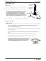
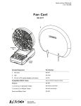
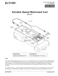
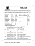
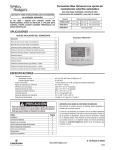
1
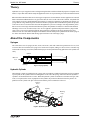
Instruction Manual
012-11726A
®
*012-11726*
Hydraulics Structures Set
ME-6984
The cover page shows the ME-6984 Hydraulics Structures model of a hydraulic boom. Pressurized fluid moves
from the syringe to the hydraulic cylinder. As the piston moves out of the cylinder, it lifts the boom structure.
®
ii
Table of Contents
Included Items . . . . . . . . . . . . . . . . . . . . . . . . . . . . . . . . . . . . . . . . . . . . . . . . . . . . . . . . . 1
Related, Required and Recommended Equipment . . . . . . . . . . . . . . . . . . . . . . . . . . . . . 2
Introduction . . . . . . . . . . . . . . . . . . . . . . . . . . . . . . . . . . . . . . . . . . . . . . . . . . . . . . . . . . . 2
Theory . . . . . . . . . . . . . . . . . . . . . . . . . . . . . . . . . . . . . . . . . . . . . . . . . . . . . . . . . . . . . . . 3
About the Components . . . . . . . . . . . . . . . . . . . . . . . . . . . . . . . . . . . . . . . . . . . . . . . . . . 3
Operation . . . . . . . . . . . . . . . . . . . . . . . . . . . . . . . . . . . . . . . . . . . . . . . . . . . . . . . . . . . . . 4
Adding Load Cells . . . . . . . . . . . . . . . . . . . . . . . . . . . . . . . . . . . . . . . . . . . . . . . . . . . . . . 6
Hydraulic Boom . . . . . . . . . . . . . . . . . . . . . . . . . . . . . . . . . . . . . . . . . . . . . . . . . . . . . . . . 7
Fork Lift . . . . . . . . . . . . . . . . . . . . . . . . . . . . . . . . . . . . . . . . . . . . . . . . . . . . . . . . . . . . . . 9
Scissors Lift . . . . . . . . . . . . . . . . . . . . . . . . . . . . . . . . . . . . . . . . . . . . . . . . . . . . . . . . . . 11
Ideal Gas Law . . . . . . . . . . . . . . . . . . . . . . . . . . . . . . . . . . . . . . . . . . . . . . . . . . . . . . . . 12
Spares Part Numbers and Summary of Extra Equipment . . . . . . . . . . . . . . . . . . . . . . . 14
Technical Support, Warranty, and Copyright . . . . . . . . . . . . . . . . . . . . . . . . . . . . . . . . . 15
®
iii
Hydraulics Structures Set
iv
®
Hydraulics Structures Set
ME-6984
1
2
3
6
4
5
7
8
9
®
Included Items
Included Items
1. Pressure Sensor Coupler
6. 10 mL Syringe
2. Syringe Coupler
7. 20 mL Syringe
3. Extension Tubing
8. 60 mL Syringe
4. Check Valve
9. Hydraulic Cylinder
5. Bleeder Valve
O-ring Drive Belt (not shown)
1
Hydraulics Structures Set
Introduction
The ME-6984 Hydraulics Structures Set is designed to be used with parts from the PASCO Structures System*.
ME-6985 Flexible I-Beams
ME-6992A Advanced Structures Set
ME-6987 Flat Beams
ME-6993 Truss Set Members
ME-6989 Physics Structures Set
ME-6997 Full Round Connectors
ME-6990 Truss Set
ME-6999A Angle Connectors
ME-6991 Bridge Set
ME-7009 Cast Beam Structures Set
*See the PASCO catalog or Web site at www.pasco.com for information about the PASCO Structures System.
The following PASCO equipment is required for the structures shown in this manual..
Required Equipment
Required Equipment
ME-6992A Advanced Structures Set
PS-2146 Pressure/Temperature Sensor
ME-8736 45-cm Steel Rod
TD-8596A Ideal Gas Law Syringe
PS-2107 Absolute Pressure Sensor
PASPORT Interfaces*
PS-2120 Rotary Motion Sensor
Data Acquisition Software*
*See the PASCO catalog or Web site at www.pasco.com for more information about interfaces and software.
Recommended Equipment
Hooked Mass Set (SE-8759)
Recommended Equipment
Large Slotted Mass Set (ME-7566 or ME-7489)
Introduction
Use the ME-6984 Hydraulics Structures Set with members of the PASCO Advanced Structures Set to build models that move and do work. Build a fork lift, scissors lift, or hydraulic boom. Use sensors to measure the pressure
and temperature of the gas or liquid in the hydraulic system, and use a sensor to measure the amount of movement
of a structure as the hydraulic system does work.
Advanced Structures Set (ME-6992A) - This set contains structure members (see the table) for building cranes,
bridges, cars, catapults, and other models.
Included Items
Qty
Included Items
Qty
Included Items
Qty
#5 Beam (24 cm long)
24
Flat 2 X 3 Beam (12.5 cm)
16
“O” Ring
12
#4 Beam (17 cm long)
54
Flat Round Connector
6
Pulley
12
#3 Beam (11.5 cm long)
54
Full Round Connector
6
Collet
24
#2 Beam (8 cm long)
24
Half Round Connector
42
Spacer
12
#1 Beam (5.5 cm long)
24
Axle (2 each of 3 lengths)
6
Sliding Connector
12
#3 Flexible Beam (11.5 cm)
16
Drive Wheel and Tire
4
Angle Connector
24
#4 Flexible Beam (17 cm)
16
Straight Connector
24
Cord Tensioning Clip
32
#5 Flexible Beam (24 cm)
16
Structures Rod Clamp
2
Yellow Cord
1 roll
Flat 3 X 4 Beam (19 cm)
16
PAStrack Connector
6
Storage box
1
Flat #4 Beam (17 cm)
16
Screw (6-32)
300
2
®
Model No. ME-6984
Theory
Theory
Hydraulics is a topic in applied science and engineering that deals with the mechanical properties of liquids. Pneumatics is a topic that deals with the study and application of the use of pressurized gas to affect mechanical motion.
Blaise Pascal described the behavior of a fluid (gas or liquid) in a closed container. Pressure applied to an enclosed
fluid is transmitted undiminished to every part of the fluid, as well as to the walls of the container. A hydraulic lift
is an example of a device that demonstrates the principle. A model of a hydraulic (or pneumatic) lift consists of a
syringe that has a large diameter piston connected to another syringe that has a small diameter piston. The pressure
is the ratio of force to area and will be the same throughout the system. For example, if the large diameter piston
has an area five times larger than the small diameter piston, the hydraulic lift will have a theoretical mechanical
advantage of five to one. In other words, a force of 10 N applied to push the small piston into the syringe would
cause a force of 50 N to be applied to push the large piston out of the piston. The large piston does the same
amount of work as is done to the small piston. The distance that the small piston is pushed into the small syringe is
five times more than the distance that the large piston will move out of the large syringe.
About the Components
Syringes
The set has three sizes of syringes (60 mL, 20 mL, and 10 mL), each with a male luer (pronounced “loo-er”) lock
at one end. The luer lock allows the syringe to be connected to couplers (tubing) or valves. There is a retainer ring
on the inside of the large end of the cylinder that helps prevent the piston from being pulled out of the cylinder too
easily.
Cylinder
Male Luer
Lock
Piston
Volume
Markings
Figure 1: Syringe (60 mL)
Hydraulic Cylinder
The hydraulic cylinder is a modified 60 mL syringe with six trunnions (cylindrical protrusions used as a mounting
or pivot point) on the cylinder and two mounting holes on the end of the syringe. The holes allow the hydraulic
cylinder to be mounted between two axles. When the hydraulic cylinder is attached to a structure and a gas (such
as air) or a liquid (such as water) is pumped into the cylinder, the pressurized fluid will cause the piston to be
pushed out of the cylinder. The part of the structure that the piston is attached to will move.
Trunnion
Holes
Cylinder
Piston
Mounting
Holes
Figure 2: Hydraulic Cylinder
®
3
Hydraulics Structures Set
Operation
Couplers
Pressure Sensor Coupler
The pressure sensor coupler has a “T” shape. The shorter arms
of the “T” have a male luer lock at one end and a female luer
lock at the other. The longer arm of the “T” has an inline quick
connector at the end for connecting to the pressure port on a
pressure sensor. Push the inline quick connector onto the pressure port, and turn the quick connector clockwise (left to right)
until the connector locks in place.
Pressure Port
Quick Connector
Figure 3: Connector onto Pressure Port
Syringe Coupler
The syringe coupler is a length of tubing about 27 cm long with a female luer lock Female luer lock
at each end. For example, the coupler connects one syringe to another, or a syringe
to the hydraulic cylinder. The syringe coupler can also connect to the other couplers and to the valves. The female luer lock screws into a threaded male luer lock.
Extension Tubing
Male luer lock
Figure 4: Luer Locks
The extension tubing is about 60 cm long with a female luer lock at one end
and a male luer lock at the other. It can be used to increase the distance
between components of the hydraulics structures set.
Closed position
Valves
Open position
Bleeder Valve
The bleeder valve has a stopcock that can be opened and closed to allow
fluid to flow through the valve or not. When the stopcock handle is perpendicular to the tubing, the valve is closed. When the stopcock handle is parallel to the tubing, the valve is open.
Figure 5: Bleeder Valve
Check Valve Assembly
The check valve assembly is a “T” shaped assembly that
has two one-way valves that allow fluid to flow through
the valve in specific directions. For example, when the
check valve assembly is connected to a syringe, fluid can
flow into the cylinder of the syringe through valve A when
the piston is pulled out. When the piston is pushed in, fluid
can flow out of the cylinder through valve B. The arrow on
each valve indicates the direction that fluid may flow
through the valve.
When the piston is
pushed in, fluid goes
through valve B to the
rest of the apparatus..
Valve B
Valve A
Cylinder
O-Ring Drive Belt
The included O-ring can be used as a ‘drive belt’ when it is
looped from one pulley to another pulley, or from a pulley
to a Rotary Motion Sensor.
Piston
When the piston is
pulled out, fluid goes
through valve A into
the cylinder.
Figure 6: Check Valve Assembly
Operation
To demonstrate Pascal’s Principle as described in the Theory section, connect the 60 mL syringe to the syringe
coupler. Pull the piston halfway out. Get a 20 mL syringe and pull its piston halfway out. Connect the smaller
syringe to the syringe coupler. Have one person hold the 60 mL syringe and another person hold the 20 mL
syringe. Have each person push in the piston of their syringe. You should notice that it is much harder to push on
4
®
Model No. ME-6984
Operation
the piston of the smaller syringe than it is to push on the piston of the larger syringe. Can you push the 20 mL
syringe’s piston all the way in? If so, can you push the 60 mL syringe’s piston all the way in while holding the 20
mL syringe’s piston in place?
Syringe
Coupler*
60 mL
Syringe
20 mL
Syringe
Figure 7: Demonstration
*not to scale
To find out how the various components work together, set up the following combination of parts: 20 mL syringe,
check valve, bleeder valve, syringe coupler, and hydraulic cylinder. Start with the pistons of both the hydraulic
cylinder and the 20 mL syringe pushed all the way in.
•
Connect the check valve assembly to the 20 mL syringe.
•
Connect the bleeder valve to the check valve assembly.
•
Connect the syringe coupler from the bleeder valve to the male luer lock on the hydraulic cylinder.
Check
Valve
Assembly
20 mL
Syringe
Stopcock
Bleeder
Valve*
Figure 8: Example
Syringe
Coupler*
Hydraulic
Cylinder
*not to scale
•
Twist the handle on the stopcock of the bleeder valve to the closed position.
•
Pull out the piston of the 20 mL syringe until the tip of the piston is at the 20 mL mark on the syringe.
•
Next, push the piston of the syringe all the way in. What happens to the hydraulic cylinder? You should have
noticed that the piston of the hydraulic cylinder moved out until the tip of the piston was close to the 20 mL
mark on the cylinder. Try it again.
•
Pull the piston of the 20 mL syringe so the piston is next to the 20 mL mark. Did the piston of the hydraulic
cylinder go back into the cylinder as you pulled the piston out of the syringe? The piston of the hydraulic
cylinder should not have moved because the check valve assembly only allows fluid to flow in specific
directions. Next, push the piston of the syringe all the way in. The piston of the hydraulic cylinder should
move to the 40 mL mark (approximately).
•
Repeat the procedure a third time and see whether the piston in the hydraulic cylinder was able to move to
the 60 mL mark.
To empty the hydraulic cylinder without disconnecting any tubing, twist the handle of the stopcock to the open
position and push the piston of the hydraulic cylinder all the way in. Fluid can flow out of the bleeder valve, but
cannot go back into the cylinder of the 20 mL syringe because of the one-way check valve.
®
5
Hydraulics Structures Set
Adding Load Cells
Using a Liquid Instead of a Gas
Fill a syringe with a liquid. Connect the syringe to the syringe
coupler. Push the piston slowly to force liquid from the
syringe into the syringe coupler until all the air is pushed out
of the coupler. Finally, connect a second syringe (or the
hydraulic cylinder) with the piston all the way in to the liquid
filled syringe coupler. When you push on the piston of the liquid filled syringe, the liquid will push against the piston of the
second syringe (or cylinder).
Leave an air space
between the liquid
and the sensor
Air space
Liquid
Figure 9: Air Space
CAUTION: If you use the Pressure Sensor Coupler and a
pressure sensor in your hydraulics structure, be sure that no
liquid enters the pressure port of the sensor. Liquid can go partway into the tubing of the Pressure Sensor Coupler
where it connects to the sensor, but leave an air space in the tubing between the liquid and the sensor.
Using a Rotary Motion Sensor to Measure Volume
You can mount a Rotary Motion Sensor (PS-2120) on a rod and attach the rod to your hydraulics structure using
Structures Rod Clamps* (ME-6986). Please see the illustration of the Hydraulic Boom on page 8. Use a thumb- *Included in the
Advanced
screw to secure a Drive Wheel* to an axle that will turn when a part of the structure moves. Arrange the sensor and Structures Set.
drive wheel so that the included O-ring will fit over the drive wheel and the largest pulley on the sensor.
Use the data acquisition software to calibrate the Rotary Motion Sensor. Set the structure so that the volume in the
hydraulic cylinder is zero. In the software, set the corresponding position of the Rotary Motion Sensor to be 0 mL
(zero milliliters). Move the structure so that the volume in the hydraulic cylinder is at its maximum. Set the corresponding position of the Rotary Motion Sensor to be the maximum volume (e.g., 60 mL).
Adding Load Cells
To measure the compression and tension forces in individual members of a structure, add load cells (e.g.,
PASCO Model PS-2200 or PS-2201) to any PASCO
Structure. Replace a beam with two shorter beams and a
load cell.
#5 beam = load cell + two #3 beams
#4 beam = load cell + two #2 beams
#3 beam = load cell + two #1 beams
Figure 10: A load cell combined with two #2 beams is
the same length as a #4 beam
Use thumbscrews to attach two beams to a load cell as shown in the figure.
When using load cells, assemble your structure with the screws loose. This
will simplify the analysis by ensuring that the members experience only tension and compression without moments.
Calibration
See the instructions that came with the load cells for details about how to connect the load cells to an interface or datalogger. Follow the instructions to calibrate the load cells and use them to collect data. (Load cells are factory
Figure 11:
calibrated; however, you can re-calibrate them in software or on the datalogCalibration fixture
ger. See the documentation for your software or datalogger for instructions.)
6
®
Model No. ME-6984
Hydraulic Boom
Hydraulic Boom
Half Round
The O-ring Drive Belt loops
from the Drive Wheel to the
Three Step Pulley on the
Rotary Motion Sensor.
3X4
Structures
Rod
Clamp
2X3
#4
2X3
Rotary
Motion
Sensor
Yellow
Cord
#4
Three
Step
Pulley
Axle
(Long)
Axle
(Small)
Full
Round
45 cm
Rod
#5
#5
#4
Structures
Rod
Clamp
Hooked
Mass
#4
Flat
Round
Axle
(Medium)
A
#3
#2
Hydraulic
Cylinder
#2
#2
#1
Half
Round
Full
Round
#3
#3
Support for slotted masses
Absolute Pressure
Sensor
Syringe Coupler
#3
Pressure Sensor
Coupler
Air space*
A. Place large slotted
masses at the end of the
base as a counterweight.
#4
Liquid*
60 mL
Syringe
* Optional: If you use a liquid,
leave an air space between
the liquid and the sensor.
Extra Equipment
Model
Structures Rod Clamp
ME-6986
45-cm Steel Rod
ME-8736
Hooked Mass Set
SE-8759
Large Slotted Mass Set
ME-7566 or ME-7489
Rotary Motion Sensor
PS-2120
Absolute Pressure Sensor
PS-2108
PASPORT Interface
see catalog
®
•
Use the sensors to measure pressure and
volume as the hooked mass is lifted. The
work done is the area under the curve.
7
Hydraulics Structures Set
Hy d r a u l i c B o o m D e ta i l s
Hydraulic Boom Details
•
Put the medium axle through a trunnion hole on the hydraulic cylinder.
Medium Axle Detail
•
Use collets and thumbscrews on both
sides of the hydraulic cylinder to position the cylinder at the middle of the
axle.
•
Use thumbscrews to attach the
medium axle to the half round connectors.
Short Axle Detail
Hydraulic
Cylinder
Medium
Axle
Half
Round
Collet
Half
Round
#2
#1
#2
#1
Short
Axle
#2
Thumbscrew
Thumbscrew
#2
#3
Put the axle through
the mounting hole at
the top of the piston.
Long Axle Detail
Half
Round
Half
Round
Spacer
#1
Collet
Spacer
Flat
Round
Collet
Long Axle
Drive
Wheel
#1
Thumbscrew
Thumbscrew
Align the drive wheel with
the larger step of the
three-step pulley on the
Rotary Motion Sensor.
Stretch the O-ring drive
belt from the drive wheel
to the step pulley.
8
#1
#4
#5
®
Model No. ME-6984
Fork Lift
Fork Lift
Yellow
Cord
Full
Round
#4
#2
Yellow
Cord
#3
Sliding
Connector
#3
Axle
(Long)
Sliding
Connector
#3
Cord
Tensioning
Clip
D
Half
Round
#4
#1
A
#2
#5
Cord
#5
Full
Round
#4
3 X4
C
#4
B
Hooked
Mass
#5
Axle
(Medium)
Axle
(Medium)
#3
A. Put a short axle
through the longer
hole in the piston cap.
C. Place large slotted
masses at the end of the
base as a counterweight.
Syringe
Coupler
Support for slotted masses
Sliding
Connector
Yellow
Cord
Full
Round
E. Cord is parallel to
the top of the boom
Cord detail
Extra Equipment
Model
Hooked Mass Set
SE-8759
Large Slotted Mass Set
ME-7566 or ME-7489
Yellow Cord (2 pack)
ME-9876
Foam core board
not included
®
To 10 mL
Syringe
Flat
Round
Tie one end of the
cord to the middle
of the #3 beam.
E. Base of fork lift is
parallel to the ground
Check
Valve
Assembly
#3
B. Put collets on both sides of D. Tie cords diagonally to
the trunnion at the bottom of thecross-brace the back of
hydraulic cylinder.
the base.
Sliding
Connector
Bleeder
Valve
#2
#2
Angle
Connector
Foam core
board (not
included)
#4
Angle
Connector
Cord
Tensioning
Clip
Sliding
Connector
E. Tighten the cord so that it is
parallel to the top of the boom
when the base of the fork lift
is parallel to the ground.
9
Hydraulics Structures Set
Fo r k L i f t D e ta i l s
Fork Lift Details
Axles and Hydraulic Cylinder Details
Piston
Cap
#1
#1
Axle
(Short)
Half
Round
Hydraulic
Cylinder
#2
Collet
Axle
(Medium)
Thumbscrew
#4
Boom Axle Details
Collet
Axle
(Long)
#2
#1
#4
#1
Short axle
goes
through the
longer hole
on the piston
cap.
Thumbscrew
Piston Cap
10
®
M o d e l N o . M E- 6 9 8 4
S c i s s o r s L if t
Scissors Lift
Use a thumbscrew
to attach the foam
core board.
Foam core
board (not
included)
Sliding
Connector
Axle
(Medium)
Hooked
Mass
Sliding Connector
Half
Round
A
#2
Straight
Connector
The sliding
connector
clamps onto
the collet.
Collet
Foam Core Board Detail
Axle
(Medium)
Collet
Full
Round
#5
Flat
Round
#5
B
Extra Equipment
Model
Hooked Mass Set
SE-8759
Yellow Cord (2 pack)
ME-9876
Foam core board
n.a.
Cord
Full
Round
#3
Full
Round
Cord
Tensioning
Clip
Cord
Hydraulic
Cylinder
Cord
Tensioning
Clip
Thumbscrew
Half
Round
#1
Axle
(Long)
#1
A. The piece of foam core
board shown is approximately
12.5 cm by 17 cm.
Lower Axle Details
C
Axle
(Long)
#1
#1
Half
Round
B. Use cord to cross-brace the
legs of the scissors lift.
Yellow
Cord
Axle
(Short)
Collet
Pulley
C. Tie one end of the
cord to the short axle.
Use a #1 Beam to connect the
two Half Rounds together
Cord
#1
Axle
(Long)
#1
Collet
Pulley
®
Tie one end of the
cord to the short axle.
11
Hydraulics Structures Set
Ideal Gas Law
Introduction
The Ideal Gas Law Apparatus, TD-8596A, allows simultaneous
measurements of temperature and pressure of a gas as it is compressed. A low thermal mass thermistor is built into the base of
the syringe to measure temperature changes inside the syringe.
The response time is around 0.5 second. The plunger is equipped
with a mechanical stop that protects the thermistor, and also
allows for a predetermined change in volume. The apparatus has a
mini stereo plug temperature connector that connects directly to a
port on a temperature sensor and a quick-release pressure connector. As the plunger of the syringe is depressed, the volume
decreases while pressure and temperature increase. NOTE: This
experiment requires the “A” version of the Ideal Gas Law Apparatus.
Ideal Gas Law
Ideal Gas Law
Apparatus
Quick-release
Connector
(remove for this
experiment)
Thermistor
Male luer lock
Temperature
Connector
Equipment Setup
Use the Hydraulic Boom structure with the Ideal Gas Law Apparatus (TD-8596A) and the Pressure/Temperature
Sensor (PS-2146).
•
Unscrew the male luer lock at the base of the Ideal Gas Law (IGL) Apparatus to remove the short
quick-release connector from the apparatus.
•
Connect the Pressure Sensor Coupler to the female luer lock on the base of the IGL Apparatus in place of the
quick-release connector.
•
Connect the side arm of the Pressure Sensor Coupler to the pressure port on the Pressure/Temperature
Sensor.
•
Connect the Syringe Coupler from the Pressure Sensor Coupler to the Hydraulic Cylinder.
•
Plug the mini stereo plug of the Temperature Connector from the IGL Apparatus into the
temperature port on the Pressure/Temperature sensor.
•
Plug the Pressure/Temperature Sensor and the Rotary Motion Sensor into a
PASCO Interface. (NOTE: You may want to use a PASport Extension
Cable to connect the Pressure/Temperature Sensor to the interface.)
PS-2500 PASport
Extension Cable
12
®
Model No. ME-6984
Ideal Gas Law
Procedure
Set the plunger for a volume of 40 cubic centimeters (cc). Hold the base of the IGL Apparatus firmly against a
sturdy horizontal surface.
Ideal Gas Law
Apparatus
TD-8596A
Pressure
Sensor
Coupler
sidearm
Temperature
Connector plug
Syringe Coupler
Pressure/Temperature
Sensor PS-2146
To PASport
Interface
PASport Extension
Cable PS-2500
Slap down on the plunger with the palm of your hand
to fully compress the gas inside the syringe. Hold this
position until the temperature and pressure have
equalized and are no longer changing.
Extra Equipment
Model
Hooked Mass Set
SE-8759
Pressure/Temperature Sensor
PS-2146
Ideal Gas Law Apparatus
TD-8596A
PASCO Interface
see catalog
PASport Extension Cable*
PS-2500
*Optional
®
13
Hydraulics Structures Set
Spares Part Numbers
Spares Part Numbers
ME-6985 Flexible I-Beam Set
ME-6997 Full Round (XYZ) Connectors
#5 Flexible Beam (24 cm) - 16
Full Round Connector - 6
#4 Flexible Beam (17 cm) - 16
Flat Connector - 6
#3 Flexible Beam (11.5 cm) - 16
PAStrack Connector* - 6
ME-6986 Structures Rod Clamp (2 pack)
ME-6987 Flat Structures Members
ME-6998A Axle Spares
1/2 by 1/4 by 1/4 Spacer - 12
Flat 3 x 4 Beam (19 cm) - 16
“O” Ring - 12
Flat #4 Beam (17 cm) - 16
Axle, Short (10.4 cm) - 2
Flat 2 x 3 Beam (12.5 cm) - 16
Axle, Medium (21.3 cm) - 2
ME-6993 Truss Set Members
Axle, Long (26.6 cm) - 2
#5 Beam (24 cm long) - 24
Collet - 24
#4 Beam (17 cm long) - 54
Pulley - 12
#3 Beam (11.5 cm long) - 54
Wheel - 4
#2 Beam (8 cm long) - 24
Tire - 4
#1 Beam (5.5 cm long) - 24
Half Round Connector - 42
ME-6994 Truss Set Screws
Screw (6 - 32) - 300
ME-6996 Cord Lock Spares
Cord Tensioning Clip - 32
*1/4 - 20 Thumbscrew
and Square Nut
ME-6999A Angle Connector Spares
Angle Connector - 24
Straight Connector - 24
Sliding Connector - 12
ME-9876 Yellow Cord (2 pack)
Cord, Braided, #18 Yellow - 2 rolls
Cord, Braided, #18 Yellow - 1 roll
Summary of Extra Equipment Needed
14
Extra Equipment (Model)
Where Used
Hooked Mass Set (SE-8759)
All
Yellow Cord (ME-9876)
All
Large Slotted Mass Set (ME-7566 or ME-7589)
Hydraulic Boom, Fork Lift, Ideal Gas Law
Structures Rod Clamp (ME-6986)
Hydraulic Boom, Ideal Gas Law
45-cm Steel Rod (ME-8736)
Hydraulic Boom, Ideal Gas Law
Rotary Motion Sensor (PS-2120)
Hydraulic Boom, Ideal Gas Law
Ideal Gas Law Apparatus (TD-8596A)
Ideal Gas Law
Pressure/Temperature Sensor (PS-2146)
Ideal Gas Law
Absolute Pressure Sensor (PS-2108)
Hydraulic Boom
PASport Interface (see catalog or web site)
Hydraulic Boom, Ideal Gas Law
Foam core board (art or office supply store)
Fork Lift, Scissors Lift
®
Model No. ME-6984
Technical Support
Technical Support
For assistance with any PASCO product, contact PASCO at:
Address: PASCO scientific
10101 Foothills Blvd.
Roseville, CA 95747-7100
Phone:
916-786-3800 (worldwide)
800-772-8700 (U.S.)
Fax:
(916) 786-7565
Web:
www.pasco.com
Email:
[email protected]
For more information about the Hydraulics Structures Set and the latest revision of this Instruction Manual, visit:
www.pasco.com/go?ME-6984
Limited Warranty For a description of the product warranty, see the PASCO catalog.
Copyright The PASCO scientific 012-11726A Hydraulics Structures Set Instruction Manual is copyrighted with all rights reserved.
Permission is granted to non-profit educational institutions for reproduction of any part of this manual, providing the reproductions are
used only in their laboratories and classrooms, and are not sold for profit. Reproduction under any other circumstances, without the
written consent of PASCO scientific, is prohibited.
Trademarks PASCO and PASCO scientific are trademarks or registered trademarks of PASCO scientific, in the United States and/or
in other countries. All other brands, products, or service names are or may be trademarks or service marks of, and are used to identify, products or services of, their respective owners. For more information visit www.pasco.com/legal.
Patents Pending: The following PASCO products have patents pending:
ME-6990 Truss Set
ME-6991 Bridge Set
ME-6992A Advanced Structures Set
ME-6993 Truss Set Members
ME-6994 Truss Set Screws
ME-6995 Road Bed Spares
ME-6996 Cord Lock Spares
ME-6997 Full Round (XYZ) Connector Spares
ME-6998 Axle Spares
ME-6999A Angle Connector Spares
PS-2198 Load Cell Amplifier
PS-2199 Load Cell and Amplifier Set
PS-2200 100 N Load Cell
PS-2201 5 N Load Cell
PS-2205 Dual Load Cell Amplifier
®
15
Hydraulics Structures Set
16
Technical Support
®