1
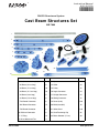
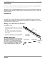
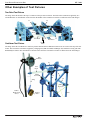
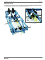
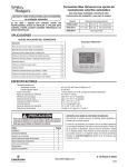
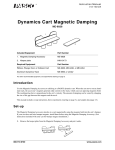
Instruction Manual
012-12111A
®
*012-12111*
PASCO Structures System
Cast Beam Structures Set
ME-7009
The cover page shows the ME-7009 Cast Beam Structures Set models of a Tension Fixture (left) and a Test Fixture (right). The tension fixture uses a hanging mass to pre-stress a cast beam member, and the test fixture can be
used after the cast beam member has dried and the mold has been removed. A hanging mass applies a load to the
cast beam, and a displacement sensor measures the amount of deflection.
The Tension Fixture and Test Fixture can be constructed concurrently with the items in this set.
®
ii
Table of Contents
Included Items . . . . . . . . . . . . . . . . . . . . . . . . . . . . . . . . . . . . . . . . . . . . . . . . . . . . . . . . . 1
Required Materials, Related and Recommended Equipment . . . . . . . . . . . . . . . . . . . . . 2
Introduction . . . . . . . . . . . . . . . . . . . . . . . . . . . . . . . . . . . . . . . . . . . . . . . . . . . . . . . . . . . 2
Making a Pre-tensioned Cast Beam . . . . . . . . . . . . . . . . . . . . . . . . . . . . . . . . . . . . . . . . 3
Assemble the Mold . . . . . . . . . . . . . . . . . . . . . . . . . . . . . . . . . . . . . . . . . . . . . . . . . . . . . . . . . . . . . . . . . 3
Assemble a Tension Fixture . . . . . . . . . . . . . . . . . . . . . . . . . . . . . . . . . . . . . . . . . . . . . . . . . . . . . . . . . . 3
Mix the “Concrete” . . . . . . . . . . . . . . . . . . . . . . . . . . . . . . . . . . . . . . . . . . . . . . . . . . . . . . . . . . . . . . . . . . 4
Add the Mixture to the Mold . . . . . . . . . . . . . . . . . . . . . . . . . . . . . . . . . . . . . . . . . . . . . . . . . . . . . . . . . . . 4
After Drying, Remove the Mold . . . . . . . . . . . . . . . . . . . . . . . . . . . . . . . . . . . . . . . . . . . . . . . . . . . . . . . . 5
Assemble a Test Fixture . . . . . . . . . . . . . . . . . . . . . . . . . . . . . . . . . . . . . . . . . . . . . . . . . 5
Other Examples of Test Fixtures . . . . . . . . . . . . . . . . . . . . . . . . . . . . . . . . . . . . . . . . . . . 6
Other Tension Fixtures . . . . . . . . . . . . . . . . . . . . . . . . . . . . . . . . . . . . . . . . . . . . . . . . . . 8
Technical Support, Warranty, Copyright and Trademarks. . . . . . . . . . . . . . . . . . . . . . . 10
Patents Pending. . . . . . . . . . . . . . . . . . . . . . . . . . . . . . . . . . . . . . . . . . . . . . . . . . . . . . . 10
®
iii
Cast Beam Structures Set
iv
®
Instruction Manual
012-12111A
®
*012-12111*
PASCO Structures System
Cast Beam Structures Set
ME-7009
1
2
12
3
15
11
4
1
14
13
10
5
9
6
17
8
16
18
7
20
19
22
23
21
Included Items
Qty
Included Items
Qty
1. Axle (2 each of 3 lengths)
6
13. Spacer
12
2. #5 Beam (24 cm long)
8
14. Collet
24
3. #4 Beam (17 cm long)
18
15. Pulley
12
4. #3 Beam (11.5 cm long)
18
16. Angle Connector
24
5. #2 Beam (8 cm long)
8
17. Straight Connector
24
6. #1 Beam (5.5 cm long)
8
18. Sliding Connector
12
7. Flat Round Connector
6
19. Screw (6-32)
150
8. Half Round Connector
14
20. Mold (reusable)
10
9. Full Round Connector
6
21. Yellow Cord
10. PAStrack Connector
6
22. Cord Tensioning Clip
32
11. “O” Ring
12
23. Rebar Member (17 cm)
30
12. Drive Wheel and Tire
4
800-772-8700
1 roll
www.pasco.com
C a s t B e a m S tr u c t u r e s S e t
ME-7009
The ME-7009 Cast Beam Structures Set consists of items from the following parts of the PASCO Structures System.
ME-6983 Cast Beam Spares
ME-6997 Full Round Connectors
ME-6993 Truss Set Members
ME-6998A Axle Spares
ME-6994 Truss Set Screws
ME-6999A Angle Connectors
ME-6996 Cord Lock Spares
Required Materials
In addition to the items included with the Cast Beam Structures Set, the following materials are required:
•
Sand,
•
Plaster of Paris,
•
Spoon, bowl or cup, and water.
Other Equipment
Other PASCO equipment is closely related to the Cast Beam Structures Set or recommended for use with the Set..
Related Equipment*
Related Equipment*
PS-2199 Load Cell and Amplifier Set
ME-6986 Structures Rod Clamps
PS-2200 100-N Load Cell
ME-6990 Truss Set
PS-2205 Displacement Sensor
ME-6991 Bridge Set
PS-2206 Dual Load Cell Amplifier
ME-6992A Advanced Structures Set
Recommended Equipment*
Recommended Equipment*
Hooked Mass Set (SE-8759)
Large Slotted Mass Sets (ME-7566 or ME-7589)
Mass and Hanger Set (ME-8979)
Braided Physics String (SE-8050)
PASPORT Interface
Data Acquisition Software
See the PASCO catalog or the web site at www.pasco.com for more information
Introduction
The Cast Beam Structures Set set consists of the Cast Beam Spares Set (ME-6983) and other items from the PASCO Structures
System. The Cast Beam Spares Set consists of a beam that is a model of the reinforcement bars (“rebar”) used in construction, and
a mold that is used to produce a model of a beam of reinforced “concrete” or prestressed “concrete”. A mixture of fine sand, plaster, and water is poured into the assembled rebar beam and mold. The assembled beam and mold are then put under tension. After
the mixture hardens and the mold is removed, the beam can be used as a #4 beam in any PASCO Structure Set.
The other items in the Cast Beam Structures Set can be used to build tension fixtures and test fixtures for the cast beams. Sensors
and weights can be used to measure the strength of the cast beam when it is attached to a test fixture or is a component of a PASCO
Structure.
About Concrete
Concrete is the most widely used construction material in the world. Non-reinforced concrete is strong in compression but weak in
tension. Any appreciable tension (for example, due to bending) will cause the concrete to crack and separate. Non-reinforced concrete must be well supported to prevent bending.
2
®
Cast Beam Structures Set
ME-7009
Reinforced Concrete
Reinforced concrete has reinforcement bars (“rebar”), grids, plates or fibers incorporated to increase the tensile strength of the concrete. Since steel is a material that has high strength in tension, it is commonly placed in concrete to add strength and to help the
concrete resist tension. Reinforced concrete is sometimes described as precast concrete.
Typical reinforced concrete uses reinforcing bars that are round in cross-section and corrugated to improve the bond between the
concrete and the steel. The coefficient of thermal expansion for concrete is similar to that of steel, so the concrete conforms to the
surface details of the steel, and the concrete’s alkaline chemical environment produces a film on the surface of the steel that makes
it more corrosion-resistant.
Prestressed Concrete
Prestressed concrete is an important method for overcoming the concrete’s natural weakness in tension. The method can be used to
produce beams, floors, or bridges with a longer span than is practical with reinforced concrete. One type of prestressed concrete is
pre-tensioned or pre-loaded concrete.
Pre-tensioned concrete is cast around already tensioned tendons (generally of high tensile steel cable or rod). The bond between the
tendon and the concrete protects the tendon and allows for direct transfer of tension. However, pre-tensioned concrete requires
stout anchoring points for the tendons so the tendons are usually in a straight line. Most pre-tensioned concrete elements are prefabricated and then transported, which limits their size.
Making a Pre-tensioned Cast Beam
Assemble the Mold
•
•
Assemble the rebar member and the mold. One way to do
this is to hold the mold in one hand and the rebar member in
the other.
Rebar
Member
Mold
First, slide one end of the rebar into one end of the mold
until the tabs of the mold make contact with the notches on
the rebar member.
Tab
•
Then rotate the rebar member down into the mold so that the
tabs on the mold click into place on the rebar member.
Assembled Rebar
Member and Mold
Tab
Assemble a Tension Fixture
One way to stretch the rebar member is to build a tension fixture
with Structure Set members (see the next page), attach one end
of the rebar member to the tension fixture, and then pull the
other end of the rebar member (for example, with weights hanging on the end of a cord suspended over a pulley). You can use
the ME-7009 Cast Beam Structures Set or the ME-6992A
Advanced Structures Set.
1. Slide the rebar into
one end of the mold.
2. Rotate the rebar into
the other end of the mold.
Caution: Do not stretch the rebar member with more than 100 N of force (the hanging weight of about 10 kg of mass).
®
3
C a s t B e a m S tr u c t u r e s S e t
ME-7009
Example Tension Fixture
#3
Slotted
Masses
#5
Sliding
Connector
#3
Cord
Tensioning Clip
Rebar Member
Mold
Sliding
Connector
#2
#1
Angle Connector
Half
Round
#3
Medium
Axle
#3
Flat Round
Cord
#5
Sliding
Connector
#4
Pulley
#3
Straight
Connector
#5
#1
Angle
Connector
Weights
Tension Fixture
•
Make sure that the two Sliding Connectors on the #5 beams are slightly loose so that they can slide freely along the beams.
•
Fasten the cord to the Cord Tensioning Clip first and then attach the Clip to the Flat Round Connector.
•
Mount the assembled mold and rebar member on the tension fixture. Put slotted masses on the #3 beam at the end of the tension fixture as a counterbalance. Attach weights up to 100 N (about 10 kilograms) to the end of the cord in order to stress the
rebar member.
Mix the Concrete
•
Mix equal quantities of fine sand and plaster of Paris. [NOTE: This mixture will make a fairly weak cast beam. Decrease the
proportion of sand to increase the strength of the cast beam.]
•
Add a small amount of water to the mixture and stir the ingredients together.
•
Continue to add water and stir until the mixture has the consistency of honey.
Add the Mixture to the Mold
•
Carefully pour the mixture into the assembled mold. You can use a spoon to ladle the mixture into the mold.
•
Frequently tap the sides of the mold to help the mixture settle and to remove bubbles. Use the spoon to push the mixture down
into the spaces around the rebar member.
•
Use a tool such as a table knife or small, flat piece of wood to smooth the top surface of the mixture.
Rebar Member
Assemble the Mold
4
Cast Beam
Pour the Plaster
Remove the Mold
®
Cast Beam Structures Set
ME-7009
After Drying, Remove the Mold
•
Let the mixture dry in the mold for 24 hours.
•
After the concrete dries, relieve the tension on the beam and then
remove the cast beam member from the tension fixture.
•
Carefully remove the mold from the cast beam. (The mold can be
cleaned and used again.)
Assemble a Test Fixture
Cast Beam member with
sand/plaster mixture
A successful test fixture provides three things:
•
Support for the cast beam member.
•
Ways to apply a load to the cast beam member.
•
Ways to measure the effect of the load on the cast beam member.
Support
Rod
Single Point Test Fixture
The example test fixture shown here provides a way for a load of several kilograms to be applied to the middle of the cast beam member
while the dial indicator of the PS-2204 Displacement Sensor measures
the beam’s deflection. The image below shows the details of how the
dial indicator is used
Half
Round
Cast
Beam
#3
Full
Round
#4
Dial
Indicator
Cable to
Displacement
Sensor
#4
Sliding
Connector
#3
Cast
Beam
Flat
Round
#3
Cord
Clip
#4
#5
#4
Large
Slotted
Masses
#3
#4
®
5
C a s t B e a m S tr u c t u r e s S e t
ME-7009
Other Examples of Test Fixtures
Two Point Test Fixture
The image shows the details of the top of a variation of the previous test fixture. The load on the Cast Beam is applied by two
I-beam Members. A dial indicator can be placed on the middle of the Cast Beam to measure its deflection as the load changes.
#2
#1
#1
Half
Round
#2
Cast Beam
Half Round
#1
Hanging
Mass
Cantilever Test Fixture
The image shows the Cast Beam in a cantilever position attached to the Full Round Connector at one corner of the top of the text
fixture. The load on the Cast Beam is applied by a hanging mass (ME-8979 Mass and Hanger Set) attached to a string (SE-8050
Braided Physics String). The dial indicator is placed on the end of the Cast Beam to measure its deflection as the load changes.
Dial
Indicator
#3
Cast
Beam
Sliding
Connector
#4
#3
#4
String
Sliding
Connector
Cable to
Displacement
Sensor
6
Hanging
Mass
#5
®
Cast Beam Structures Set
ME-7009
Bridge Test Fixture
The image shows a bridge structure with a Cast Beam member. The load is applied by a hanging mass suspended from a cross
member, and the tension through the Cast Beam is measured with a 100 N Load Cell (PS-2201).
#4
#3
#2
#3
#4
Cast
Beam
#2
#4
Load
Cell
Hanging Mass
Typical Test Results
Stress/Strain Test Fixture
The PASCO Stress/Strain Apparatus (AP-8213) can be used to test the strength of the Rebar Member by itself. Use diagonal pliers
or strong clippers to cut the ends off the two pieces of “rebar” in the Rebar Member. Mount a single piece of “rebar” into the two
Coupon Clamps on the Stress/Strain Apparatus. Turn the crank clockwise to apply tension to the “rebar” until it fails (breaks)..
Coupon
Clamp
Rebar
Member
Coupon Clamp
Rotary
Motion
Sensor
Force
Sensor
®
Sample Data
7
C a s t B e a m S tr u c t u r e s S e t
ME-7009
Other Tension Fixtures
Wheel and Axle
Another way to apply a pre-tensioning load to a Cast Beam member as it dries is to use a Drive Wheel and Axle rather than a hanging mass over a pulley. In the image below, the load is measured with a 100 N Load Cell (PS-2201) and the load limit is 100 N.
Cast Beam
and Mold
•
Tie the cord to a
collet on the axle
and use the Drive
Wheel and Tire
to wind the cord
around the axle..
Load Cell
Cord
Collet
•
Sliding
Connector
Use the Sliding
Connector as a
brake to hold the
Drive Wheel and
Tire in place.
Press the Sliding
Connector against the tire
after you tighten the cord.
Spacer
Axle
Collet
Collet
Drive
Wheel
and Tire
Double Pulley and Axle
Use a hanging mass and two pulleys. The second pulley multiplies the load applied to the Cast Beam member as it dries. In the
image below, the load is measured by a 100 N Load Cell and the load limit is 100 N.
Slotted
Sliding
• Tie a “V” shaped
Flat Round
Mass
Connector
harness of cord
#1
Connector
around both sides
Cast Beam
of the collets on
and Mold
the front axle.
Sliding
Connector
#1
Sliding
Connector
Load
Cell
Axle
Cord
•
Put spacers on
each side of
both pulleys.
Collet
Angle
Connector
Sliding
Connector
Put the Collet in
the ‘jaw’ of the
Sliding Connector.
Collet
Hanging
Mass
8
®
Cast Beam Structures Set
ME-7009
Triple Pulley and Axle
Use a hanging mass and three pulleys. The three pulleys multiply the applied load on the drying Cast Beam more than a single pulley or a double pulley can. The ‘block-and-tackle’ arrangement of three pulleys has an Ideal Mechanical Advantage (IMA) of
3-to-1. The applied load is measured by a 100 N Load Cell and the load limit is 100 N.
Sliding
Connector
Put the Collet in
the ‘jaw’ of the
Sliding
Connector.
V-shaped
cord harness
Detail of the V-shaped
Cord Harness
Pulley
Spacer
Collet
®
9
C a s t B e a m S tr u c t u r e s S e t
ME-7009
Technical Support
For assistance with any PASCO product, contact PASCO at:
Address: PASCO scientific
10101 Foothills Blvd.
Roseville, CA 95747-7100
Phone:
916-786-3800 (worldwide)
800-772-8700 (U.S.)
Fax:
(916) 786-7565
Web:
www.pasco.com
Email:
[email protected]
For the latest revision of this Instruction Manual, visit:
www.pasco.com/go?ME-7009
Limited Warranty For a description of the product warranty, see the PASCO catalog. Copyright The PASCO scientific 012-12111A Cast
Beam Structures Set Instruction Manual is copyrighted with all rights reserved. Permission is granted to non-profit educational institutions for reproduction of any part of this manual, providing the reproductions are used only in their laboratories and classrooms, and are not sold for profit. Reproduction under any other circumstances, without the written consent of PASCO scientific, is prohibited. Trademarks PASCO and PASCO scientific are trademarks or registered trademarks of PASCO scientific, in the United States and/or in other countries. All other brands, products, or service
names are or may be trademarks or service marks of, and are used to identify, products or services of, their respective owners. For more information
visit www.pasco.com/legal.
Patents Pending
10
The following PASCO products have patents pending:
ME-6987 Flat Structures Members
PS-2198 Load Cell Amplifier
ME-6990 Truss Set
PS-2199 Load Cell and Amplifier Set
ME-6991 Bridge Set
PS-2200 100 N Load Cell
ME-6992A Adv. Structures Set
PS-2201 5 N Load Cell
ME-6995 Road Bed Spares
PS-2205 Dual Load Cell Amplifier
®