1
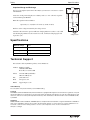
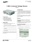
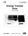
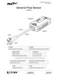
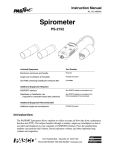
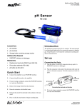
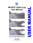
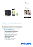
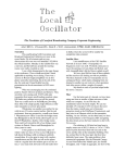
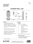
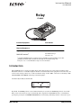
In s t r u c ti on M an u a l
®
0 1 2 - 0 9 4 5 9A
Relay
al
rm
o
N
p
m
n
o
m
o
A
ct
iv
at
C
ed
m
V
o
30
NU
A
D
LA
CT
IVA
TIO
N
0)
MA
IVA
TE
83
D
:A
CT
(1
.
LE
ON
IN
T T
E O
R
FA
C
E
5
A
R
E
L
A
lt
, Y
u
m
(S
P
M D
ax T
im )
®
(3
.
23
C
0)
I64
62
CI-6462
Included Equipment
Part Number
Relay
CI-6462
Required Equipment
Digital Adapter
PS-2159
PASPORT Interface1
See PASCO catalog or
www.pasco.com
1
Compatible PASPORT interfaces include the Xplorer (PS-2000), Powerlink (PS-2001), Xplorer GLX
(PS-2002), AirLink (PS-2005), and USB Link (PS-2100). See the PASCO catalog, visit
www.pasco.com, or contact PASCO tech support for more information.
Introduction
This CI-6462 Relay is a single-pole double-throw switch designed for sense-and-control experiments using
DataStudio software or a standalone Xplorer GLX. It can automatically switch equipment on and off in any AC
or DC circuit carrying as much as 5 A with a maximum voltage of 30 V. Make connections to the Relay’s Activated, Normal, and Common jacks using 4 mm banana plugs.
Schematically the Relay looks like this:
Activated
Common
Normal
By default, the Normal position is closed. When the Relay is activated, the Activated position is closed. The
Relay can be activated in two ways: automatically with a signal from a PASPORT interface, or manually by
pressing the pressing the red Manual Activation button on the Relay. (The Relay must be connected to a pow-
800-772-8700
www.pasco.com
Relay
D a t a S t u d io S e t u p
ered PASPORT interface for manual activation.) Whenever it is activated, the green
LED on the Relay turns on.
DataStudio Setup
Note: Follow these steps if you are using any PASPORT interface connected to a computer. Go to
page 3 for instructions on setting up an Xplorer GLX without a computer.
1.
Connect the Relay’s ¼ inch phone plug to Channel 1 of a Digital Adapter.
2.
Connect the Digital Adapter to the PASPORT interface.
3.
Connect the interface to your computer.
4.
Connect at least one sensor (such as a temperature sensor) to the same or a separate PASPORT interface. This sensor will provide the input used to control the
Relay.
Tip: The above steps can be performed in any order. For instructions on connecting your interface, refer to the documentation that came with it.
5.
Start DataStudio (if it does not start automatically).
Note: If you see the “Welcome to DataStudio” window, select Create Experiment.
6.
DataStudio automatically detects a device connected to the Digital Adapter and
opens the “timers” list. Select Relay Control.
Select Relay Control
Next, you will define the behavior of the Relay in DataStudio’s Calculator window.
Follow steps 7–13 for one simple example of how to do this. This example assumes
that you have connected a temperature sensor, but another sensor can be substituted.
7.
Click the Calculate button to open the Calculator window.
8.
In the definition field, type the following (overwriting
the default “y = x” definition):
Click to open Calculator
Relay State = outputstate(1, 1, T >30)
9.
Click the Accept button.
10. Drag Temperature (°C) from the Data List and drop it
onto Please define the variable “T” in the Calculator.
Drag Temperature to the Calculator
11. Click the Start button to start data collection.
12. Hold the temperature sensor in your hand. When the measured temperature
increases above 30 °C, the Relay activates: the LED on the Relay lights, and you
may hear the Relay click. Allow the temperature sensor to cool; at less than
30 °C, the Relay deactivates.
Note: The LED on the Digital Adapter is always in the opposite state to the LED on the Relay. The
adapter’s LED is off when the Relay is activated.
13. Click the Stop button to stop data collection.
Note: Go to page 4 for more information on the output-control functions used in DataStudio.
2
®
Model No. CI-6462
X p l o r e r G L X S e t u p ( S ta n d a lo n e M o d e )
Xplorer GLX Setup (Standalone Mode)
Note: Follow these steps if you are using a GLX without a computer.
1.
Connect the Relay’s ¼ inch phone plug to Channel 1 of a Digital Adapter.
2.
Connect the Digital Adapter to Port 1 of the Xplorer GLX.
3.
Connect at least on sensor (such as a temperature sensor) to the GLX. This sensor
will provide the input used to control the Relay.
4.
Turn on the GLX.
Tip: The above steps can be performed in any order.
5.
The GLX automatically detects a device connected to the Digital Adapter and
opens the “timers” list. Select Relay Control. (Relay Control is the last selection
on the list; press the up arrow to jump directly to it.)
Next, you will define the behavior of the Relay in the GLX Calculator screen. Follow
the steps 6–13 for one simple example of how to do this. This example assumes that
you have connected a temperature sensor, but another sensor can be substituted.
+
F3
6.
Press
7.
Press F1 three times to open the third Functions menu. Select out outstate
from that menu.
8.
Press
9.
Press F1 three times to open the third Functions menu again. Select > (the
greater than sign).
F2
to open the Calculator screen.
Select Relay Control
from the GLX
timers list
to open the [Data] menu. Select Temperature with units of (°C).
10. Type 30; then press
.
The definition in the Calculator screen should now look like this:
outputstate(1,1,[Temperature (°C)]>30)
11. Press
to start data collection.
12. Hold the temperature sensor in your hand. When the measured temperature
increases above 30 °C, the Relay activates: the LED on the Relay lights, and you
may hear the Relay click. Allow the temperature sensor to cool; at less than
30 °C, the Relay deactivates.
Note: The LED on the Digital Adapter is always in the opposite state to the LED on the Relay. The
adapter’s LED is off when the Relay is activated.
13. Press
to stop data collection.
®
3
Relay
Ou t p u t - c o n tr o l Fu n c t io n s
Output-control Functions
Note: The examples in the remainder of this Instruction Manual are presented as they would
appear in DataStudio, though most of them are applicable to the GLX used in standalone mode.
For more information on defining calculations on the GLX, see the GLX Users’ Guide.
outputstate(Adapter, AdapterChannel, state)
Let’s take a closer look the definition that you typed into the calculator for the example on page 2 or 3:
Adapter
AdapterChannel
State
Relay State = outputstate(1, 1, T>30)
name
outputstate function
The text to the left of the equal sign is the name of the calculation; you can type anything you want there. The important part of the calculation, on the right side, is the
outputstate function and its three arguments enclosed in parentheses and separated by
commas.
The first argument, Adapter, identifies the digital adapter to be controlled. In DataStudio, the first adapter that you connect is number 1, the second is number 2, etc.; if you
have only one adapter, it is always number 1 regardless of where it is plugged in. On
the GLX in standalone mode, the number of the adapter is the number of the port that
it is plugged into (1, 2, 3, or 4).
The second argument, AdapterChannel, identifies the channel of the digital adapter
that the Relay is plugged into. In the example above, it is equal to 1. If you had
plugged the Relay into channel 2 of the adapter, you would set the argument equal to
2.
Tip: You can use two relays connected to the same digital adapter, and more if you have multiple
adapters. For each relay, create one calculation that includes the outputstate function and
uniquely addresses it using the Adapter and AdapterChannel arguments.
The third argument, state, is what actually controls the Relay. When state = 0, the
Relay is “normal”. When state ≠ 0 (i.e. when the argument equals anything other than
zero), the Relay is activated. To say it another way: the Relay is activated only when
state is true.
The state argument is usually a logical expression made up of one or more of the
operators and functions described below.
Logic Operators and Functions
A logic function has two possible values: 0 and 1. A logic operator (< or >) is used to
build an expression that can have a value of 0 or 1.
Less Than and Greater Than If an expression such as a < b is true, then it
equals 1. If the expression is false, then it equals 0.
inrange(min, max, x) This function has three arguments: the first two, min and
max, define the upper and lower limit of a range, and the third, x, is an input value to
4
®
Model No. CI-6462
Ex a m p le s
be compared with that range. If min ≤ x ≤max, then the function equals 1. If x < min
or x > max, then the function equals 0.
and(a, b) This function equals 0 if either of the arguments equals 0; otherwise the
function equals 1.
or(a, b) This function equals 0 if both of the arguments equal 0; otherwise the
function equals 1.
not(x) This function equals 1 if the argument equals 0; otherwise the function
equals 1.
Examples
The input that controls the relay can be any measurement or combination of multiple
measurements from any sensor. Below are some examples.
Temperature Control
Temperature control may be desirable on a variety of apparatus such as an incubator
(made with a low-power light bulb and a box), a small greenhouse equipped with a
cooling fan, or a thermal cavity (such as PASCO part TD-8580A).
You can control the temperature by having the Relay turn on a fan when the apparatus
is too hot, or by turning on a heater when it is too cold. The example from page 2 or 3,
outputstate(1, 1, T>30)
could be used for either purpose, depending on whether there were a fan circuit connected to the Normal jack or a heater circuit connected to the Activated jack.
You can also use the Relay to control a bell or light to indicate when the temperature
is within an acceptable range (or not) with a definition such as:
outputstate(1, 1, inrange(20, 30, T))
This would activate the Relay when the temperature is between 20 °C and 30 °C.
Fan Cart on Inclined Track
In this example, a fan cart starts pushing itself up an inclined track whenever it gets
close to the bottom.
Setup a fan-equipped cart on an inclined track with a motion sensor (part PS-2103) at
the lower end. Connect the Relay so that the fan turns on when the Relay is activated.*
Enter this equation in the Calculator:
outputstate(1, 1, and(x>0.25, V <0))
*The PASCO Fan Accessory (part ME-9491) can
be controlled by the
Relay via the cable pictured below, which you
can make with commonly
available parts.
to fan
accessory
3.5 mm (1/8 inch)
mono phone plug
Define x as position and V as velocity.
Start data collection and release the cart about 25 cm from the motion sensor (oriented
so that the fan will push the cart up the incline). The fan is on when the cart is closer
than 25 cm and rolling toward the sensor; otherwise it is off.
Change the incline of the track, or change the distance at which the fan turns on and
observe the results.
®
4 mm banana
plugs
to Relay
5
Relay
Sp e c if ic a tio n s
Capacitor Charge and Discharge
Relay
Enter this equation in the Calculator:
10 W
Normal
Common
Create the circuit pictured (right). Use a battery such as a “AA” cell and a capacitor
such as PASCO part SE-8626.
Activated
Note: If you are using the Xplorer GLX for this example, you must use it connected to a computer
with DataStudio.
1.5 V +
outputstate(1,1, or(and(V<1, derivative(2,V)>0), V <0.5))
Define V as the voltage measured by the voltage sensor.
Start data collection. The capacitor will start charging. When V reaches 1 volt, it will
start discharging. When V has decreased to 0.5 volt, it will start charging again and
repeat the cycle.
1F
V
voltage sensor
Specifications
Maximum Voltage
30 V
Maximum Current
5A
Cord Length
1.7 m
Dimensions
10 cm x 7 cm x 3 cm
Technical Support
For assistance with any PASCO product, contact PASCO at:
Address: PASCO scientific
10101 Foothills Blvd.
Roseville, CA 95747-7100
Phone:
916-786-3800 (worldwide)
800-772-8700 (U.S.)
Fax:
(916) 786-3292
Web:
www.pasco.com
Email:
[email protected]
Limited Warranty
For a description of the product warranty, see the PASCO catalog.
Copyright
The PASCO scientific 012-09459A Relay Instruction Manual is copyrighted with all rights reserved. Permission is granted to non-profit
educational institutions for reproduction of any part of this manual, providing the reproductions are used only in their laboratories and
classrooms, and are not sold for profit. Reproduction under any other circumstances, without the written consent of PASCO scientific,
is prohibited.
Trademarks
PASCO, PASCO scientific, DataStudio, PASPORT, Xplorer, and Xplorer GLX are trademarks or registered trademarks of PASCO scientific, in the United States and/or in other countries. All other brands, products, or service names are or may be trademarks or service marks of, and are used to identify, products or services of, their respective owners. For more information visit
www.pasco.com/legal.
6
®