1
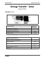
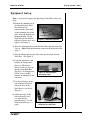
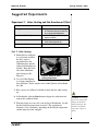
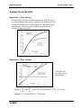
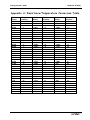
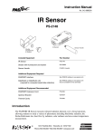
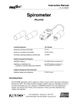
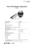
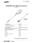
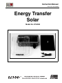
Instruction Manual
Manual No. 012-08428A
Energy Transfer
Solar
Model No. ET-8593
Energy Transfer Solar
Model No. ET-8593
Table of Contents
Equipment List........................................................... 3
Introduction ............................................................. 4
Equipment Description .................................................. 4
Equipment Setup ..................................................... 5-6
Suggested Experiments ................................................. 7
Experiment 1: Solar Heating and the Greenhouse Effect .......................................................... 7-8
Experiment 2: Solar Constant (Advanced Lab) ....................................................................... 9-10
Sample Data/Results...................................................11
Appendix A: Temperature/Resistance Conversion Table ............12
Appendix B: Technical Support ....................................... 13
Appendix C: Copyright and Warranty Information .................. 13
2
®
Model No. ET-8593
Energy Transfer - Solar
Energy Transfer - Solar
Model No. ET-8593
Equipment List
1
3
2
4
Included Equipment
1. Solar Box , 10.75 x 8.25 x 2.50”
Replacement
Model Number*
648-08412
2. Plastic Cover, 11.0 x 8.25 x 1.25”
650-065
3. Aluminum Plate, 6.50 x 9.0”, 85 g
648-08413
4. Cable assembly
514-08366
*Use Replacement Model Numbers to expedite replacement orders.
Additional Equipment Required
PASPORT™ Xplorer or a laptop computer
PS-2000
DataStudio® software
Various
(See PASCO catalog)
Temperature Sensor or Thermistor Sensor or Ohmmeter/Multimeter
PS-2125 or CI-6527A
(For ohmmeter, see
PASCO catalog.)
Piece of cardboard (1 ft. square)
NA
A computer
NA
®
3
Energy Transfer - Solar
Model No. ET-8593
Introduction
The Energy Transfer-Solar box (ET-8593) can be used for
demonstrating the concept of solar heating, including the greenhouse
effect.
Equipment Description
a) Plastic Cover
The clear, plastic cover snaps onto the Solar box and acts as insulator
to isolate and trap air inside, reduce convection currents, and
demonstrate the greenhouse effect. The cover is very transparent to
visible light but not infrared light.
b)Aluminum Plate
The aluminum plate is painted a non-reflective flat black that absorbs
light very well. The hot aluminum plate re-radiates in the far infrared
region, and thus the heat energy is trapped under the cover.
The reverse side of the aluminum plate is not painted. The plate can be
flipped inside the box to study differences in solar heating and/or
cooling between the aluminum and black surfaces. The aluminum
plate can be removed to measure its mass. The white, plastic knob also
serves as an indicator for the sun’s angle. When the sun is
perpendicular to the aluminum plate, no indicator shadow appears on
the plate.
c) Solar Box
The Solar Box holds the aluminum plate and plastic cover. On the side
of the box is a rod clamp for mounting the box to a rod stand. When
mounted to a rod stand, the box can be adjusted to the sun’s angle.
d) Thermistor
Inside the Solar Box is a 10K thermistor for measuring temperature.
The thermistor cables are not removable from the box. The thermistor
contact (metal lug) is fastened in the center, on the underside of the
aluminum plate. The side jacks on the Solar Box allow you to connect
a Temperature Sensor or ohmmeter to the thermistor.
4
Note: The thermistor’s
temperature range is -35oC
to +135oC (242,800 to 265
ohms).
®
Model No. ET-8593
Energy Transfer - Solar
Equipment Setup
Note: A rod stand is required for adjusting the Solar Box to the sun’s
angle.
1. Remove the thumbscrew on
the aluminum plate. Place
the thermistor lug
underneath the center hole
on the aluminum side of the
plate. Insert the thumbscrew
through the hole. On the
black side, put the shadow
indicator over the screw and
tighten (See Figure 1).
thumbscrew
thermistor cable
thermistor lug
Figure 1: Thermistor position
2. Place the aluminum plate inside the Solar Box, with the black side
face up. (Note: Keep the thermistor contact on the underside of the
plate.)
3. Snap the bottom and top tabs of the clear, plastic cover onto the
Solar Box. (See Figure 3).
4. Using the thermistor cable,
connect the Temperature
Sensor (or Thermistor
Sensor) to the two jacks on
the side of the Solar Box
(Figure 2). If a Temperature
Sensor is not available,
connect an ohmmeter to the
side jacks.
Figure 2: Connecting the
thermistor cable
5. Use the rod clamp (on the
side of the Solar Box) to
mount the base of the
Solar Box to a rod stand
(Figure 3).
6. Adjust the angle of the
box such that the sun's
rays enter the box
perpendicularly. Use the
white knob indicator as a
guide.
®
Figure 3: Mounting the
Solar Box to a rod stand
5
Energy Transfer - Solar
Model No. ET-8593
Note: If there is no shadow on the plate, the sun’s rays are
perpendicular to the plate.
7. Plug the Temperature Sensor into a PASPORT Xplorer. To take a
temperature reading, click the Start button on Xplorer. (Note: The
Xplorer data can later be uploaded into DataStudio and viewed in a
DataStudio graph display.)
OR
If you are using an ohmmeter (instead of a Temperature Sensor),
turn on the meter and take a resistance measurement. To find the
temperature, use the resistance-to-temperature conversion chart in
Appendix A.).
WARNING: To avoid
burns or bodily injury,
when heating the box, do
not overheat the box
(above 100oC) and do not
touch either side of the
aluminum plate or the
thermistor contact.
OR
If you are using a laptop and a temperature probe, plug the
Temperature Sensor plug into a USB port on your laptop computer.
Launch DataStudio and click the Start button to collect data.
CAUTION: Overheating
the box may permanently
damage the thermistor
and the plastic lid. The
thermistor’s maximum
temperature capacity is
135oC.
6
®
Model No. ET-8593
Energy Transfer - Solar
Suggested Experiments
Experiment 1: Solar Heating and the Greenhouse Effect
Equipment Required
Energy Transfer - Solar (ET-8593)
Temperature Sensor (PS-2125)
or Thermistor Sensor (CI-6527A)
or an Ohmmeter/Multimeter
Rod Stand (ME-9355)
PASPORT Xplorer (PS-2000) or
laptop computer
Piece of cardboard
Temperature vs. Resistance
Chart (See Appendix A)
DataStudio Software
Part I: Solar Heating
1. Mount the box with plate
to a rod stand, such that
the Sun's angle is
perpendicular to the
aluminum plate and the
white plastic knob has no
shadow. Keep the black
side of the aluminum
plate facing up (See
Figure 4).
Figure 4: Setup for Solar
Heating Experiment
2. Use a PS-2000 Xplorer
or a laptop computer for
data collection. Set the sample rate in either Xplorer or DataStudio
for 2 Hz.
3. Have a piece of cardboard available to shade the box while setting
up.
4. In DataStudio, click the Start button to begin data collection and
remove the cardboard shade.
5. With the plastic cover on, take a run of data in DataStudio. Let the
box heat until the temperature levels off. (The approximate
duration is 10 to 30 minutes, depending on the outside temperature
and the intensity of the sunlight.)
®
CAUTION: Overheating
the box may permanently
damage the thermistor
and the plastic lid. The
thermistor’s maximum
temperature capacity is
135oC.
7
Energy Transfer - Solar
Model No. ET-8593
Note: Watch the angle of the sun. The angle of the sun must be 90
degrees to the box while you are collecting data. You might have to
adjust the angle of the box during the run.
6. Repeat step 5 with the plastic cover off.
Analysis
1. Look carefully at both curves at the start of the run. The slope (rate of
heating) for the uncovered box should be larger than for the covered
box. Why?
2. Which has the highest final temperature, the covered box or the
uncovered box?
WARNING: To avoid
burns or bodily injury,
when heating the box, do
not overheat the box
(above 100oC) and do not
touch either side of the
aluminum plate or the
thermistor contact.
3. Which curve has a more constant heating rate? Why?
Part II.Solar Heating Comparison: Aluminum vs. Black Surface
Compare the aluminum side up to black side up with the cover on.
Which surface is a better absorber of energy? Look at not only how
fast the plate heats up, but collect data long enough to look at the final
temperature. The black side should heat up much faster than the
aluminum side, but does the black side reach a higher final
temperature?
Part III. Cooling Comparison: Aluminum vs. Black Surface
For both sides (aluminum and black), start with the plate hot (Let it sit
in the sun), and then move the plate to the shade to watch it cool.
Which surface cools faster? Which is a better emitter of energy? Try
cooling both with and without the cover on the Solar Box.
8
®
Model No. ET-8593
Energy Transfer - Solar
Experiment 2: Solar Constant
Equipment Required
Energy Transfer - Solar (ET-8593)
Temperature Sensor (PS-2125) or
Thermistor Sensor (CI-6527A)
Rod Stand (ME-9355)
PASPORT Xplorer (PS-2000) or
laptop computer
Piece of cardboard
Measuring tape and scale
DataStudio Software
*Note: This is a more advanced lab. Two Temperature Sensors or one
temperature sensor and a thermometer are required. You will use one
Temperature Sensor to measure the temperature of the aluminum plate
and a second Temperature Sensor (or thermometer) to measure the
ambient temperature.
1. Disconnect the thermistor from the plate and measure the mass of the
plate. Measure the plate’s size and calculate the area of plate.
2. Cool the plate to 10oC to 20oC below the outside temperature.
(You can stick the plate in a refrigerator or use an ice cube). Be
sure the plate is dry.
3. Place the aluminum plate in the Solar Box with the black side
facing up to the sun. Do not use the plastic cover.
4. Connect the Temperature Sensor to the side jacks of the box with
the supplied cable. (If possible, have a second temperature sensor
measuring outside temperature. Note: The second Temperature
Sensor (or a thermometer) must be in the shade for an accurate
determination of the outside ambient air temperature.)
5. Recheck the sun’s angle. You might have to adjust the box relative
to the sun’s angle during the run. (Note: The angle of the sun
relative to the box must be 90 degrees.)
6. In DataStudio, create a graph of temperature vs. time. For the time
variable, use seconds (not minutes) on the graph.
WARNING: To avoid
burns or bodily injury,
when heating the box, do
not overheat the box
(above 100oC) and do not
touch either side of the
aluminum plate or the
thermistor contact.
CAUTION: Overheating
the box may permanently
damage the thermistor
and the plastic lid. The
thermistor’s maximum
temperature capacity is
135oC.
7. In DataStudio, click the Start button to begin recording (at the
default sample rate of 2 Hz.). Heat the box until it is 10oC to 20oC
above outside temperature.
®
9
Energy Transfer - Solar
Model No. ET-8593
Analysis
a) Find the slope of the line tangent to the curve at outside ambient air temperature. Do not
use the Slope Tool. Highlight a small section at outside ambient temperature. At ambient
temperature, the heating is only being caused by the sunlight. Below the ambient
temperature, the surrounding air is cooling the container. Above the ambient temperature, the
surrounding air is heating the container.
slope = ∆T
-------- = change in temperature/change in time
∆t
b) Theory for heat flow
Q = mc∆T where Q =heat, c=specific heat, and
∆T
= change in temperature
∆T
Q =
Power = ---mc ------∆t
∆t
∆T
mc ------∆t
Intensity = Power
----------------- = --------------Area
Area
where
∆ T-----∆t
is the slope of the graph.
c)Using your slope and the other measured quantities, calculate the intensity of the sun's light.
The intensity (solar constant) at the top of the Earth's atmosphere is about 1400 Watts/m2. On
a good clear day with the sun high in the sky, you can get over 1000 Watts/m2 on the surface.
For Further Study:
a) Compare the intensity at noon to later in the day.
b) Compare a clear day to a slightly overcast day.
c) Compare summer to winter.
10
®
Model No. ET-8593
Energy Transfer - Solar
Sample Data/Results
Experiment 1: Solar Heating
The covered box has the final higher temperature. With the covered
box, the greenhouse effect occurs. Light enters the transparent cover,
but the infrared light is not re-radiated back out. The infrared light
heats the plate. Also, the cover traps the hot air inside the box,
isolating and insulating the air.
Experiment 2: Solar Constant
Note: This data
was taken late in
the afternoon.
∆ TQ- = mc -----Power = ---= (0.085 kg) (900 joules/kg/oC) (0.361) = 27.6 watts
∆t
∆t
Intensity = 27.6 watts/0.038 m2 = 730 watts/m2
®
11
Energy Transfer - Solar
Model No. ET-8593
Appendix A: Resistance/Temperature Conversion Table
Resistance
(Ohms)
32,660
31,040
29,500
28,060
26,680
25,400
24,180
23,020
21,920
20,880
19,900
18,970
18,090
17,260
16,460
15,710
15,000
14,320
13,680
13,070
12,490
11,940
11,420
10,920
10,450
10,000
9,574
9,166
8,778
8,408
8,058
7,722
7,404
7,098
12
Temperature
(Celsius)
0
1
2
3
4
5
6
7
8
9
10
11
12
13
14
15
16
17
18
19
20
21
22
23
24
25
26
27
28
29
30
31
32
33
Resistance
(Ohms)
6,808
6,532
6,268
6,016
5,776
5,546
5,326
5,118
4,918
4,726
4,544
4,368
4,202
4,042
3,888
3,742
3,602
3,468
3,340
3,216
3,098
2,986
2,878
2,774
2,674
2,580
2,488
2,400
2,316
2,234
2,158
2,082
2,012
1,942
Temperature
(Celsius)
34
35
36
37
38
39
40
41
42
43
44
45
46
47
48
49
50
51
52
53
54
55
56
57
58
59
60
61
62
63
64
65
66
67
Resistance
(Ohms)
1,876
1,813
1,751
1,693
1,637
1,582
1,530
1,480
1,432
1,385
1,341
1,298
1,256
1,216
1,178
1,141
1,105
1,071
1,038
1,006
975
945
916
889
862
836
811
787
764
742
720
699
679
Temperature
(Celsius)
68
69
70
71
72
73
74
75
76
77
78
79
80
81
82
83
84
85
86
87
88
89
90
91
92
93
94
95
96
97
98
99
100
®
Model No. ET-8593
Energy Transfer - Solar
Appendix B: Technical Support
For assistance with the ET-8593 Energy Transfer - Solar or any other PASCO products,
contact PASCO as follows:
Address: PASCO scientific
10101 Foothills Blvd.
Roseville, CA 95747-7100
Phone:
(916) 786-3800
FAX:
(916) 786-3292
Web:
www.pasco.com
Email:
[email protected]
Appendix C:
Copyright and Warranty Information
Copyright Notice
The PASCO scientific 012-08428A Energy Transfer - Solar Manual is copyrighted and all
rights reserved. However, permission is granted to non-profit educational institutions for
reproduction of any part of the 012-08428A Energy Transfer - Solar Manual providing the
reproductions are used only for their laboratories and are not sold for profit. Reproduction
under any other circumstances, without the written consent of PASCO scientific, is
prohibited.
Limited Warranty
PASCO scientific warrants the product to be free from defects in materials and workmanship
for a period of one year from the date of shipment to the customer. PASCO will repair or
replace, at its option, any part of the product which is deemed to be defective in material or
workmanship. The warranty does not cover damage to the product caused by abuse or
improper use. Determination of whether a product failure is the result of a manufacturing
defect or improper use by the customer shall be made solely by PASCO scientific.
Responsibility for the return of equipment for warranty repair belongs to the customer.
Equipment must be properly packed to prevent damage and shipped postage or freight
prepaid. (Damage caused by improper packing of the equipment for return shipment will not
be covered by the warranty.) Shipping costs for returning the equipment after repair will be
paid by PASCO scientific.
®
13