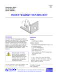
1
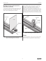
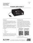
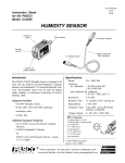
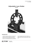
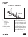
012-05629A
3/95
$1.00
Instruction Sheet
for the PASCO
Model OS-8518
GEOMETRIC OPTICS KIT
Screen
en
ing
Scre
2 Lenses in
Separate Holders
View
Basic Optics
Bench
Figure 1: Geometric Optics equipment
Introduction
Limited Warranty
The PASCO OS-8518 Geometric Optics Kit includes:
PASCO scientific warrants this product to be free from
defects in materials and workmanship for a period of one
year from the date of shipment to the customer. PASCO
will repair or replace, at its option, any part of the product
which is deemed to be defective in material or workmanship. This warranty does not cover damage to the product
caused by abuse or improper use. Determination of
whether a product failure is the result of a manufacturing
defect or improper use by the customer shall be made
solely by PASCO scientific. Responsibility for the return
of equipment for warranty repair belongs to the customer.
Equipment must be properly packed to prevent damage
and shipped postage or freight prepaid. (Damage caused
by improper packing of the equipment for return shipment will not be covered by the warranty.) Shipping
costs for returning the equipment, after repair, will be
paid by PASCO scientific.
– Basic Optics Bench
– Screen (attaches to Bench)
– Lenses (2) in Holders
• +100 mm Lens
• +200 mm Lens
The OS-8518, Geometric Optics Kit is included in the
OS-8515 Basic Optics System but can be purchased separately. The OS-8515 system includes:
– OS-8517 Light Source
– OS-8516 Ray Optics Kit
– OS-8518 Geometric Optics Kit
© 1995 PASCO scientific
This instruction sheet written/edited by: Jon Hanks
better
10101 Foothills Blvd. • P.O. Box 619011 • Roseville, CA 95678-9011 USA
Phone (916) 786-3800 • FAX (916) 786-8905 • email: [email protected]
ways to
teach physics
Geometric Optics
012-05629A
Mounting the Screen and Lenses to the
Optics Bench (OS-8518)
The lens holders simply snap into place on the bench.
See Figure 3, Mounting Lens Holders on Bench. To
slide the lens holder along the bench, grasp the lens
holder at its base and squeeze the locking clip on the side
of the holder. Continue to squeeze the locking clip while
the lens is slid along or removed from the bench. When
the locking clip is released the lens is held firmly in place.
To mount the viewing screen to the Optics Bench, slide
the square nut into the center T-slot in the bench. See
Figure 2 below, Mounting Screen on Bench.
Optics
Bench
Optics Bench
Lens Holder
Screen
Hole for Rack
Storage
Locking
Clip
Hole for Rack
Storage
Position
Indicator
en
ing
Scre
w
Vie
T-Slot
Figure 3: Mounting Lens Holder on Bench
Nut
Storage
All parts (lens holders, screen, etc.) have a hole to allow
them to be hung on a peg board for compact storage.
Figure 2: Mounting Screen on Bench
2