1
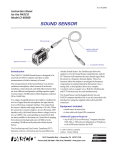
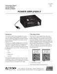
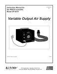
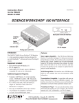
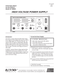
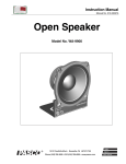
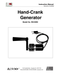
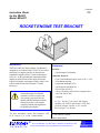
012-06418A 10/97 $1.00 Instruction Sheet for the PASCO Model ME-6617 ROCKET ENGINE TEST BRACKET Introduction Equipment The PASCO ME-6617 Rocket Engine Test Bracket is designed for use with the PASCO CI-6537 Force Sensor and a PASCO computer interface to determine the magnitude of impulse of Estes model rocket engines (series A D). By permitting the measurement of the impulse of an Estes model rocket engine, the Rocket Engine Test Bracket can augment rocketry studies, such as those detailed in the Estes Educator Teacher Resources1. Included: The Rocket Engine Test Bracket should be used only in a supervised class setting by personnel who are familiar with the National Association of Rocketry Safety Code and after complying with any state regulations for igniting rocket engines.1 1 For more information, contact Estes Industries, 1295 H. St., Penrose, CO 81240, 1-800-820-0202 ® Rocket Engine Test Bracket Additional Required: Estes Model Rocket Engine (series A, B, C, or D) Estes launch controller Large Rod Stand (ME-8735) 90 cm support rod (ME-8738) Force Sensor (CI-6537) Science Workshop and a PASCO computer interface (300, 500, or 700) computer ➤ Note: Because of its remote data logging capability, the PASCO 500 Interface is the most practical computer interface to use with the Rocket Engine Test Bracket. © 1997 PASCO scientific Editor: Sunny Bishop better 10101 Foothills Blvd. • P.O. Box 619011 • Roseville, CA 95678-9011 USA Phone (916) 786-3800 • FAX (916) 786-8905 • web: www.pasco.com ways to teach science Rocket Engine Test Bracket 012-06418A Important Safety Notes ➤ Read all the warnings and follow the instructions provided with the Estes Model Rocket Engine and Igniter. ➤ Review the National Association of Rocketry (NAR) Safety Code prior to igniting a rocket engine. Point number 9 of the NAR Safety Code is of particular importance: The system I use to launch my model rocket will be remotely controlled and electrically operated. It will contain a launching switch that will return to off when released. The system will contain a removable safety interlock in series with the launch switch. All persons will remain at least 15 feet (5 meters) from the model rocket when I am igniting model rocket engines totalling 30 newtonseconds or less of total impulse . . . I will use only electrical igniters recommended by the engine manufacturer that will ignite model rocket engines within one second of actuation of the launching switch. ➤ Choose an asphalt or concrete launch area free of any combustible material, animals, or people. ➤ Use a remote electrical launching system that includes a safety key feature to ignite the model rocket engine. Remote electrical launching is the only safe and approved way to ignite model rocket engines. ➤ Install igniters only when you are outdoors and almost ready to launch. ➤ Wear safety glasses when installing the igniter and connecting the cables to the launch controller. ➤ Never put the safety key in the launch controller unless the exhaust area of the rocket engine is clear. Otherwise, accidental ignition causing injury may result. ➤ Before igniting the rocket engine, check to be sure there are no objects, people, or animals near the exhaust of the model rocket engine. ➤ Remove the safety key as soon as the rocket engine is ignited. ➤ Do not allow the igniter leads or alligator clips on the cables to touch each other. ➤ Wait 10 minutes after ignition of the rocket engine before touching the Rocket Engine Test Bracketit will be hot. ➤ Comply with any regulations from your state or country for igniting rocket engines. ➤ Use ony Series AD Estes model rocket engines. ➤ In the event of a misfire, remove the safety key from the controller and wait 60 seconds before disconnecting the micro-clips. Then replace the igniter. ➤ Never store or transport model rocket engines with igniters installed. 2 012-06418A Rocket Engine Test Bracket ➤ Note: Refer to the Users Guide to Science Workshop (Sampling Options) for details on adjusting the sampling rate. Setup Set up the equipment 1. Remove the hook from the end of the Force Sensor. Use a small screwdriver to connect the Rocket Engine Test Bracket to the Force Sensor in place of the hook (Figure 1). Remove hook. 3. Open a Graph display. ➤ Note: If you are using a 500 computer interface, prepare it for remote data logging (refer to the Users Guide to Science Workshop (Remote Data Measurement with the Science Workshop 500 Interface). Screw into threaded connector. screwdriver Prepare for Ignition 1. Move the equipment to the launch site. T AR E Force Sensor Figure 1 Attaching the Rocket Engine Test Bracket to the Force Sensor 2. Insert the igniter into the rocket engine and spread the wires apart, leaving the paper separator in place (Figure 3). igniter 2. Mount the Force Sensor on the support rod in one of two ways: horizontally (Figure 2a) or vertically (Figure 2b). a tape separator igniter plug Wires must not touch each other! b E T RA Force Sensor at least 80 cm Rocket Engine Test Bracket a b c d AR E T Figure 3 Inserting the igniter into the model rocket engine rod stand Figure 2 a) horizontal mount b) vertical mount ➤ Note: Carefully follow the instructions that accompany the rocket engine and igniter. 3. Clip the alligator clips of the cables from the launch controller to the igniter wires. Set up Science Workshop 1. Set up the Force Sensor in Science Workshop on analog channel A. Note: Do not allow the igniter wires or alligator clips to touch each other. Be certain that the safety key is not in the launch controller. Insure that the cables are well away from the exhaust area (Figure 4) and the computer interface is as far away from the exhaust area as possible. 2. Adjust the sampling rate for the Force Sensor to 500 Hz. 4. Plug the Force Sensors DIN connector into analog channel A. 3. Insert the model rocket engine into the test stand with the engines exhaust port pointing away from the Force Sensor. 3 Rocket Engine Test Bracket 012-06418A 10 Integration area = 8.51336 N s igniter wires to electronic launch controller 0 Force Sensor’s TARE button Run #1 Force (N) 5 model rocket engine to computer interface 0 Keep exhaust area clear! 2 4 6 8 10 12 14 E T Time (s) AR Figure 5 Graph of typical experimental results of a test of an Estes C6-3 model rocket engine cable clips Figure 4 Completed experimental setup Suggested Activity 5. Press the TARE button on the Force Sensor (Figure 4). Calculate the expected height of a rocket propelled with an identical rocket engine from the force and mass data, and compare with the actual height attained in a flight test. ➤ Note: For the 500 interface in remote mode, press the TARE button after the log button has been pressed and the LED has flashed 10 times. 6. Check the exhaust area to ensure it is clear of any combustible material, people, or animals. Limited Warranty PASCO scientific warrants the product to be free from defects in materials and workmanship for a period of one year from the date of shipment to the customer. PASCO will repair or replace, at its option, any part of the product which is deemed to be defective in material or workmanship. The warranty does not cover damage to the product caused by abuse or improper use. Determination of whether a product failure is the result of a manufacturing defect or improper use by the customer shall be made solely by PASCO scientific. Responsibility for the return of equipment for warranty repair belongs to the customer. Equipment must be properly packed to prevent damage and shipped postage or freight prepaid. (Damage caused by improper packing of the equipment for return shipment will not be covered by the warranty.) Shipping costs for returning the equipment after repair will be paid by PASCO scientific. Data Collection 1. Insert the safety key into the launch controller. 2. Begin recording data and move to 15 feet (5 meters) away from the Rocket Engine Test Bracket. 3. Ignite the rocket. 4. After the burn, stop recording data. Data Analysis 1. In Science Workshop, click the statistics button and select Integration from the pop-up menu, and click the Autoscale button to resize the graph. 2. Select the area under the curve and record the integrated value (impulse of the rocket engine). 3. Use the smart cursor to determine the time to the ejection charge. Address: 4. Compare your recorded values with the expected values for the type of you are using. Phone: FAX: email: web: The exclamation point within an equilateral triangle is intended to alert the user of important operating and safety instructions that will help prevent damage to the equipment or injury to the user. 4 PASCO scientific 10101 Foothills Blvd. P.O. Box 619011 Roseville, CA 95678-9011 (916) 786-3800 (916) 786-8905 [email protected] www.pasco.com