1
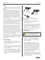
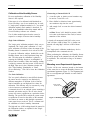
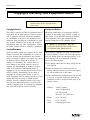
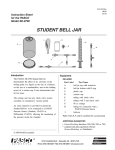
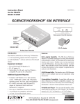
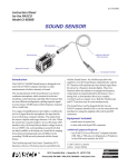
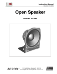
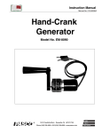
012-06437B 11/99 $1.00 Instruction Sheet for the PASCO Model CI-6559 HUMIDITY SENSOR vented top plate DIN connector to computer interface % R HUELA MID TIV ITY E 9 55 -6 CI Humidity Sensor % TY DI MI OR HUENS S interface cable with DIN connectors to Humidity Sensor aperture for sensing element Introduction Specifications The PASCO CI-6559 Humidity Sensor is designed to be used with the PASCO ScienceWorkshop® computer interface and DataStudio™ or ScienceWorkshop® software. The Humidity Sensor may be used for making single readings or continuous monitoring of relative humidity (RH). Equipment Included: • CI-6559 Humidity Sensor • 6-foot cable with 8-pin DIN connectors • instruction sheet • storage bag Range: Accuracy: -no calibration 0% - 100% RH Voltage Output: 0 - 10V (0% - 100% RH) ± 5% RH at 60% RH ± 8% at 90% RH -with saturated salt calibration ± 2% 0% - 100% @25 °C Resolution: 0.1% RH Response Rate: 15 seconds in slow moving air Repeatability: ± 0.5% RH Connector Type: 8-pin DIN, ScienceWorkshop interface compatible DIN Connector PASCO ScienceWorkshop® software, version 2.2.5 or higher. ® 6 7 8 % Or 1: analog output (+), 0-10 V 2: analog output (-), signal ground 3: no connection 4: +5 VDC power 5: power ground 6: +12 VDC power 7: -12 VDC power 8: no-connection RE HU LA MID TIVE ITY Additional Equipment Required: • Any PASCO ScienceWorkshop® computer interface. PASCO DataStudio™ software 1 3 5 4 2 © 1997 PASCO scientific Author: Steve Miller better 10101 Foothills Blvd. • P.O. Box 619011 • Roseville, CA 95678-9011 USA Phone (916) 786-3800 • FAX (916) 786-8905 • email: [email protected] ways to teach science Humidity Sensor 012-06437B Theory A The Humidity Sensor consists of two basic elements: the humidity sensing element and the signal condition amplifier. B ScienceWorkshop™ RES 1 T L O A s ANALOG CHANNELS B n C Interface 2 G S P 500 O ® ON DIGITAL CHANNELS GAIN=1,10:ISOLATED GAIN = 1,10: REF TO GND GAIN = 1: REF TO GND ScienceWorkshop™ 500 P Plug into any analog channel. RES 1 L O ® A s ANALOG CHANNELS B n C Interface 2 G T O S The humidity sensing element is powered by +5 volts DC and outputs a DC voltage that is proportional to the relative humidity of the air surrounding the sensing element. The element is an integrated circuit, which features high reliability and fast response, and is contamination resistant. The output voltage of the sensing element varies between 0.8 and 3.9 VDC, which corresponds to a relative humidity ranging from 0 to 100%, respectively. ON DIGITAL CHANNELS GAIN=1,10:ISOLATED GAIN = 1,10: REF TO GND GAIN = 1: REF TO GND % REL HUM ATI IDIT VE Y 9 55 CI-6 Plug into any analog channel. Y IT R ID O M S U N H SE % ITY MIDOR HUENS S % CI-6 559 RELATIVE HUMIDITY % Figure 1. Connecting the Humidity Sensor into the computer interface. Two stages of amplification are provided to condition the signal from the humidity sensing element for input to the ScienceWorkshop computer interface. The output of these two stages will range from 0 to 10 VDC, which will correspond to 0 to 100% humidity. 3. Select "Humidity Sensor" from the Sensors list (DataStudio™) or drop-down menu (ScienceWorkshop®). 4. Open a display window, such as the graph display. In DataStudio, doubleclick the graph icon in the display list. In ScienceWorkshop, drag and drop the graph icon over the Humidity Sensor icon. The first stage is used to reference the sensor output range from 0 to 3.1 volts. This establishes 0 volts as the 0% relative humidity point. The second stage applies a gain of about 3.2, which causes the maximum sensor output, 3.1VDC, to increase to 10VDC, which corresponds to a 100% relative humidity. Both DataStudio and ScienceWorkshop software take the 0 - 10V output from the sensor, multiply it by 10 and display the result as relative humidity. 5. Additional display windows can be opened by following the procedure in step 4. Operational Notes To prevent damage to the Humidity Sensor or other equipment, do not immerse the Humidity Sensor in fluid. The Humidity Sensor can be plugged directly into any ScienceWorkshop computer interface or connected to the interface box using the supplied cable with 8-pin DIN connectors. The sensing element resists contamination vapors, such as organic solvents, chlorine, and ammonia. The element is also unaffected by water condensation. Setup Procedure 1. Connect the Humidity Sensor and any analog channel into the PASCO Computer Interface with interface cable (Figure 1A), ➤ For best results: The Humidity Sensor is capable of responding fairly quickly to changes in the humidity. However, in order to respond, a sample of the environment (air) must reach the sensing element (positioned near the sensor aperture). The sensor responds quickest when it is in a slow moving air stream. This may be accomplished by moving the sensor slowly with your hand during data collection. or Insert the DIN plug of the Humidity Sensor directly into any analog channel on the PASCO Computer Interface (Figure 1B). 2. Open the Experiment Setup window in DataStudio or ScienceWorkshop. Click and drag the analog plug icon to the analog channel icon that matches the analog port you are using for the Humidity Sensor. ➤ To avoid errors: The sensing element can be affected by the bright light of the sun. Do not point the aperture for the sensing element directly toward the sun or a bright light. 2 Humidity Sensor 012-06437B Calibration of the Humidity Sensor Constructing a Saturated Salt Cell For most applications, calibration of the Humidity Sensor is not required. 1. A one-liter glass or plastic-covered container may be used as a vessel for a cell. If the sensor is to be calibrated with DataStudio or ScienceWorkshop, one of two methods may be used: 1) "single point" calibration method or 2) "two point" calibration method. (Each method is described, in detail, in the DataStudio online help manual and the ScienceWorkshop software user manual.) 2. Place distilled or deionized water approximately one centimeter deep into the vessel. 3. Add enough "salt" to create the desired saturated solution. ➤ Hint: Excess "salt" should be present (visible as it settles to the bottom of the vessel) to ensure saturation of the solution. Use of either method requires that the sensor be exposed to a sample of known relative humidity. Single Point Calibration A closed cell constructed with NaCl as the excess "salt" will have a RH of about 75%. A similar constructed cell using MgCl will have a RH of about 33%. The "single point" calibration method is fairly easy to implement. The "single point" calibration is a "two point" calibration (see below) where the output of the Humidity Sensor is assumed to be 0 volts at 0% RH. The "single point" calibration method may also be accomplished with a saturated salt cell. To open the Calibration window, double-click on the Humidity Sensor icon in the Experiment Setup window. The other point for calibration is gained by exposing the Humidity Sensor to an atmosphere of known relative humidity. When the humidity reading is relatively constant, enter the known % RH value in the High Value area in the Calibration window and click "Take Reading" (DataStudio) or "Read" (ScienceWorkshop). Click OK to close the Calibration window. When performing the calibration, the Humidity Sensor should be placed in the saturated salt cell and allowed to equilibrate. This could take as long as 30 minutes or more. Mounting on an Experimental Apparatus Use the 1/4-20 screw connector located on the bottom of the sensor box to secure the Humidity Sensor to an experimental apparatus (Figure 2). The alignment hole fits over an alignment pin included on some PASCO apparatuses. Two Point Calibration The "two point" calibration is more difficult because the sensor must be exposed to two distinctively different atmospheres of different levels of known relative humidities to read high and low values for calibration. This difficulty may be overcome by using a device known as a saturated salt cell. alignment hole 1/4-20 screw connector A saturated salt cell is an enclosed system containing a saturated salt solution and air. The air in the closed system will come to equilibrium at a particular relative humidity. The specific RH at which the system comes to equilibrium is based on the ability of the saturated salt solution to extract or add (through evaporation) water vapor from or to the air. This is a common tool for calibration of relative humidity instruments. Figure 2. Mounting connector and alignment hole. The high and low % RH readings should be entered in the Calibration window, as explained in the "Single Point Calibration" section. 3 Humidity Sensor 012-06437B Copyright, Warranty, and Equipment Return Please—Feel free to duplicate this manual subject to the copyright restrictions below. Copyright Notice Equipment Return The PASCO scientific 012-06437A instruction sheet is copyrighted and all rights reserved. However, permission is granted to non-profit educational institutions for reproduction of any part of the Humidity Sensor instruction sheet providing the reproductions are used only for their laboratories and are not sold for profit. Reproduction under any other circumstances, without the written consent of PASCO scientific, is prohibited. Should the product have to be returned to PASCO scientific for any reason, notify PASCO scientific by letter, phone, or fax BEFORE returning the product. Upon notification, the return authorization and shipping instructions will be promptly issued. äÿNOTE: NO EQUIPMENT WILL BE ACCEPTED FOR RETURN WITHOUT AN AUTHORIZATION FROM PASCO. Limited Warranty When returning equipment for repair, the units must be packed properly. Carriers will not accept responsibility for damage caused by improper packing. To be certain the unit will not be damaged in shipment, observe the following rules: PASCO scientific warrants the product to be free from defects in materials and workmanship for a period of one year from the date of shipment to the customer. PASCO will repair or replace, at its option, any part of the product which is deemed to be defective in material or workmanship. The warranty does not cover damage to the product caused by abuse or improper use. Determination of whether a product failure is the result of a manufacturing defect or improper use by the customer shall be made solely by PASCO scientific. Responsibility for the return of equipment for warranty repair belongs to the customer. Equipment must be properly packed to prevent damage and shipped postage or freight prepaid. (Damage caused by improper packing of the equipment for return shipment will not be covered by the warranty.) Shipping costs for returning the equipment after repair will be paid by PASCO scientific. ➀ The packing carton must be strong enough for the item shipped. ➁ Make certain there are at least two inches of packing material between any point on the apparatus and the inside walls of the carton. ➂ Make certain that the packing material can not shift in the box, or become compressed, allowing the instrument to come in contact with the edge of the packing carton. 4 Address: PASCO scientific 10101 Foothills Blvd. P.O. Box 619011 Roseville, CA 95678-9011 Phone: (916) 786-3800 FAX: (916) 786-8905 email: [email protected]