1
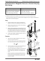
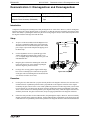
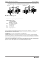
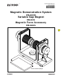
I n s tr u c ti o n M a nu a l
012- 12722A
®
*012-12722*
Magnetic Demonstration System
EM-8644B
Variable Gap Magnet
EM-8618
Magnetic Force Accessory
EM-8642A
EM-8618 Variable Gap Magnet
The EM-8644B Magnetic Demonstration System consists of the EM-8618 Variable Gap Magnet and the
EM-8642A Magnetic Force Accessory. You can use the components of the system to demonstrate magnetic
induction, the magnetic force on a current-carrying wire, diamagnetism, and paramagnetism.
®
ii
Table of Contents
Included Items . . . . . . . . . . . . . . . . . . . . . . . . . . . . . . . . . . . . . . . . . . . . . . . . . . . . . . . . . 1
EM-8642A Magnetic Force Accessory and Recommended Equipment . . . . . . . . . . . . . 2
Introduction . . . . . . . . . . . . . . . . . . . . . . . . . . . . . . . . . . . . . . . . . . . . . . . . . . . . . . . . . . . 2
About the Equipment . . . . . . . . . . . . . . . . . . . . . . . . . . . . . . . . . . . . . . . . . . . . . . . . . . . . 3
Demonstration 1: Magnetic Induction . . . . . . . . . . . . . . . . . . . . . . . . . . . . . . . . . . . . . . . 5
Demonstration 2: Magnetic Force on a Current Carrying Wire Swing . . . . . . . . . . . . . . . 6
Demonstration 3: Diamagnetism and Paramagnetism . . . . . . . . . . . . . . . . . . . . . . . . . . 7
Technical Support, Warranty, and Copyright . . . . . . . . . . . . . . . . . . . . . . . . . . . . . . . . . . 8
®
iii
V ar i a bl e G ap M a gn e t
iv
®
Magnetic Demonstration System
EM-8644B
Variable Gap Magnet
EM-8618
Magnetic Force Accessory
EM-8642A
Adjustment
Screw (2)
Magnets
Magnet Holder (2)
Threaded Hole
(1/2” by 13
thread)
Pole Pieces
Base
Bumper (4)
EM-8618 Item
EM-8618 Item
Variable Gap Magnet
Pole Piece (2)
CAUTION: STRONG MAGNETIC FIELD. Do not put the magnets close (within a few centimeters) to anything that would be harmed by a strong magnetic field, such as magnetic media, computer hard disks, or monitors.
®
1
Ma g ne t ic De m on s tr a t io n S y s t em
In tr o d uc t i on
The EM-8618 Variable Gap Magnet is designed to be used with parts from the PASCO EM-8642A Magnetic
Force Accessory.
6
5
4
2
3
1
7
EM-8642A Magnetic Force Accessory*
EM-8642A Items
EM-8642A Items
1. Swing Assembly
2. Aluminum Tube
3. Glass Rod
4. Eddy Current Blade with Slits
5. Eddy Current Blade (solid)
6. Eddy Current Blade with Slots
7. Mounting Rod
Spool of thread (not shown)
*See the PASCO catalog or Web site at www.pasco.com for more information about the EM-8642A Magnetic Force Accessory and
other PASCO products.
The following PASCO equipment is recommended for use with the EM-8618 Variable Gap Magnet and the
EM-8642A Magnetic Force Accessory..
Recommended Equipment*
Recommended Equipment*
ME-9355 Base and Support Rod
SE-9720A Power Supply
ME-8988 25-cm Stainless Steel Rod, Threaded
SE-9750 Banana Plug Patch Cords
SE-9442 Multi Clamp
SE-8645 Hand Crank Generator
*See the PASCO catalog or Web site at www.pasco.com for more information about PASCO labware and equipment.
Introduction
Use the EM-8618 Variable Gap Magnet with the EM-8642A Magnetic Force Accessory to teach the concepts of
magnetic induction, diamagnetism, paramagnetism, and magnetic force on a current-carrying wire.
2
®
E M- 8 6 44 B
012-12722A
A bo u t th e E qu i p me n t
About the Equipment
Variable Gap Magnet
The Variable Gap Magnet consists of two one inch (2.54 centimeter) diameter neodymium magnets on an iron
base with adjustable magnet holders. Two flat iron pole pieces are included to provide a uniform magnetic field
when needed. The gap between the faces of the two magnets can be varied from 0.5 cm to 8.9 cm by turning the
adjustment screws. The base has a threaded hole for mounting on a 12.7 mm diameter threaded support rod (1/2”
diameter by 13 thread) such as the PASCO ME-8988 25-cm Stainless Steel Threaded Rod. The base can be
mounted on a non-threaded support rod that is less than 12.7 mm (1/2”) in diameter using the thumbscrew on the
side of the base.
The approximate magnetic field strength without the pole pieces in place is shown in Table 1.1. Note that the magnetic field strength may vary from magnet to magnet. (These sample measurements were taken with a Model 4048
F.W. Bell Gauss/Tesla Meter.)
Table 1.1:
Gap (cm)
Magnetic Field at Poles
(tesla/gauss)
Magnetic Field between Poles
(tesla/gauss)
0.5
1.02 T / 10200 G
1.00 T / 10000 G
0.6
1.00 T / 10000 G
0.95 T / 9500 G
1.0
0.85 T / 8500 G
0.75 T / 7500 G
8.9
0.55 T / 5500 G
0.35 T / 3500 G
The magnetic field is intense between the magnet faces, but drops off to about 30 gauss at the outside edges of the
magnets. Nevertheless, do not put the magnets close to magnetic media, computer hard disks, monitors, or other
items that would be harmed by an intense magnetic field.
Pole Pieces
The flat iron pole pieces are 7.95 cm long
(3.125“) by 4.44 cm wide (1.75”) by 0.5 cm
thick (0.19”). When the pole pieces are
placed on the magnet faces, the magnetic
field between the pole pieces is relatively
uniform except at the edges of the pole
pieces. With a separation of 1 cm (0.4 in)
between the pole pieces, the magnetic field
varies between 8500 and 9000 gauss.
Pole Pieces
Center the pole
piece on the
magnet.
Be careful when handling the pole pieces
near the magnets. Use the adjustment
screws to separate the two magnets. Slide
the pole piece onto the magnet from the
edge of the magnet. Center each pole piece
on the magnet face.
Try to prevent the pole pieces from striking hard against the neodymium magnets
because the impact may break or chip
the magnets.
®
Thumbscrew
Figure: Magnet with Pole Pieces
3
Ma g ne t ic De m on s tr a t io n S y s t em
A bo u t t he E q ui p m en t
EM-8642A Magnetic Force Accessory
The Magnetic Force Accessory consists of the following components:
•
Aluminum eddy current blades (solid, with slots, and with slits) for demonstrating magnetic induction and
magnetic braking
•
Mounting rod for supporting the blades or the swing assembly
•
Swing assembly for demonstrating the magnetic force on a current-carrying wire
•
Aluminum tube (paramagnetic material)
•
Glass rod (diamagnetic material)
•
Thread for suspending the aluminum tube and glass rod
Eddy Current Theory
Eddy currents are currents induced in a conductor when the conductor is exposed to a changing magnetic field due
to the relative motion of the conductor and the source of the magnetic field, or due to variation of the magnetic
field over time. A circulating flow of electrons will form in the body of the conductor. These circulating eddies of
current generate a magnetic field that opposes the change of the original magnetic field as described by Lenz’s law.
The opposing magnetic fields cause drag forces between the conductor and the magnet. The drag forces cause
“magnetic braking”.
Magnet Positioning
The Variable Gap Magnet may be used in four different free-standing positions or can be mounted on a support
rod. The following diagrams show the various positions. The threaded hole in the base accepts a 1/2” (12.7 mm)
threaded rod (13 thread per inch) such as the PASCO ME-8988 25-cm Stainless Steel Rod. The hole also accepts
non-threaded rods less than 12.7 mm (1/2”) in diameter. The thumbscrew on the side of the base holds the magnet
in position on a non-threaded rod..
ME-8988 25-cm
Stainless Steel Rod
Upright
Upside down
SE-9444 Multi
Clamp
On side
ME-9355 Large
Base and Rod
On support
rod
On end
Figure: Positions for the Variable Gap Magnet
4
®
E M- 8 6 44 B
012-12722A
De m on s t r at i on 1 : M ag n et i c I nd u ct i on
Demonstration 1: Magnetic Induction
Equipment Needed
Variable Gap Magnet (EM-8618)
Equipment Needed
Large Base and Rod (ME-9355)
Magnetic Force Accessory (EM-8642A)
Use the eddy current blades and the Variable Gap Magnet to demonstrate magnetic induction.
Setup
1.
Slide the mounting rod onto a support rod and tighten the set
screw at the end of the mounting rod to hold it in place.
2.
Hang the solid eddy current blade on the end of the mounting bar by placing the hooked end of the blade into one of
the slots at the end of the bar.
3.
Raise or lower the mounting bar so that the blade is centered
between the two magnets.
4.
Adjust the magnets so that the gap between the magnets is
just wide enough to allow the blade to fit between the magnets without touching.
5.
Slide the Variable Gap Magnet away enough away from the
blade so that the blade can swing freely.
Solid eddy
current blade
Figure: Demo Setup
Explain to the class that the eddy current blades are made of aluminum, which is a non-ferromagnetic material and is not attracted
to magnets.
Procedure
1.
With the magnet away from the blade, swing the blade to
show that it swings freely on the mounting bar.
2.
Slowly slide the Variable Gap Magnet back into position so
that the blade is centered between the magnets. (Go slowly.
If the magnet is moved into place too quickly, the blade will
move.)
3.
With the magnet in place, swing the blade to show that the
oscillations are now damped because of the induced eddy
currents in the moving blade.
4.
Figure: Swing the Blade
Repeat the procedure for the eddy current blade with slots and the eddy current blade with slits.
The blade with slots is less damped than the solid eddy current blade. The blade with slits is only slightly damped.
®
5
Ma g ne t ic De m on s tr a t io n S y s t em
De m on s tr a ti o n 2 : Ma g ne ti c Fo r c e on a Cu r -
Demonstration 2: Magnetic Force on a Current-Carrying
Wire Swing
Equipment Needed
Equipment Needed
Variable Gap Magnet (EM-8618)
Large Base and Rod (ME-9355)
Magnetic Force Accessory (EM-8642A)
Patch Cord, 2 (SE-9750)
12 V DC Power Supply (SE-9720A)*
(Mini Generator (SE-8645) – optional)
*The PASCO Hand-held Mini Generator (SE-8645) can be used as the power source instead of the DC power supply.
Use the swing assembly and pole pieces with the Variable Gap Magnet and a power supply to demonstrate the
magnetic force on a current-carrying wire.
Setup
1.
Slide the mounting rod onto a support rod and tighten the
thumbscrew at the end of the mounting rod to hold it in place.
2.
Plug the swing assembly into the two holes in the mounting
rod from the underside of the rod.
3.
Place the Variable Gap Magnet on its end with the pole pieces
attached so the magnetic field between the pole pieces is vertical. Adjust the gap between the pole pieces and the position
of the magnet so that the horizontal part of the swing is centered between the pole pieces and can move back-and-forth.
4.
Connect a power supply or a hand-crank generator to the top
part of the holes in the mounting rod.
Swing
assembly
Procedure
1.
•
Turn on the power supply and adjust the current so that the
swing moves forward or backward.
The direction that the swing will move depends on the direction of the current and the orientation of the magnetic field.
F = qv × B
6
2.
Reverse the position of the patch cords on the mounting rod.
The swing should move in the opposite direction.
•
You can also demonstrate the dependence of the direction of
the swing movement on the direction of the current if you
include a double-pole, double-throw switch (DPDT) in the
circuit.
•
NOTE: It is possible to use the SE-8645 Mini Generator as
the power source in this demonstration. It is easy to reverse
the current by simply reversing the direction that the Mini
Generator is cranked.
Patch cords
to power
supply
The
current-carrying
swing moves
due to the
magnetic force.
Figure: Demo Setup
®
E M- 8 6 44 B
012-12722A
De m on s t r at i on 3 : D i am a gn e ti s m an d
Demonstration 3: Diamagnetism and Paramagnetism
Equipment Needed
Equipment Needed
Variable Gap Magnet (EM-8618)
Large Base and Rod (ME-9355)
Magnetic Force Accessory (EM-8642A)
Tape
Introduction
Compared to ferromagnetism, diamagnetism and paramagnetism are weak effects. However, when a diamagnetic
material is placed in a strong magnetic field, it is possible to see that the material is repelled by the magnetic field.
On the other hand, if a paramagnetic material is placed in a strong magnetic field, it will be noticeably attracted to
the magnetic field and will align itself with the field.
Setup
1.
Tie pieces of thread (included with the Magnetic Force
Accessory) around the middle of the glass rod and the
aluminum tube. Secure the thread in place with a small
piece of tape to prevent the sample from slipping out of
the thread loop.
2.
Use the adjustment screws to expand the gap of the
Variable Gap Magnet until the gap is about 3.8 cm
(1.5”) or slightly larger than the length of the glass rod
and aluminum tube.
3.
Hang the glass rod from the mounting bar so that the
rod is at the same level as the Variable Gap Magnet
when the magnet is placed on its side.
4.
For large class viewing, put the magnet and the large
base on an overhead projector and focus the projector
on the glass rod. The mounting bar will not obstruct the
view because it will be out of focus.
Mounting rod
Thread
Glass rod
Figure: Demo Setup
Procedure
1.
For the glass rod, show that when you place the rod parallel to the magnetic field lines, the rod rotates and
oscillates about an equilibrium position which is perpendicular to the magnetic field lines of the magnet.
Eventually the glass rod will come to rest in this equilibrium position but it takes longer than you will want
to wait. Instead, use you hand to stop the glass rod in the equilibrium position (perpendicular to the field).
Then, to show that the rod is held in position by the magnetic field, slowly rotate the magnet about the axis
formed by the thread. The glass rod will rotate, always staying perpendicular to the magnetic field lines.
2.
Follow the same procedure for the aluminum tube (the paramagnetic sample). However, instead of initially
aligning it parallel to the magnetic field lines, put the aluminum tube perpendicular to the field to show that
it will rotate into an equilibrium position that is parallel to the magnetic field lines. When the aluminum tube
®
7
Ma g ne t ic De m on s tr a t io n S y s t em
Te c h ni c a l S u pp or t
is in the equilibrium position, rotate the magnet about the axis formed by the thread. The aluminum tube will
rotate with the magnet, always staying parallel to the magnetic field lines.
Glass rod
Aluminum tube
Initial Equilibrium
position position
Equilibrium Initial
position position
Figure: Demo Setup
Technical Support
For assistance with any PASCO product, contact PASCO at:
Address: PASCO scientific
10101 Foothills Blvd.
Roseville, CA 95747-7100
Phone:
916-786-3800 (worldwide)
800-772-8700 (U.S.)
Fax:
(916) 786-7565
Web:
www.pasco.com
Email:
[email protected]
For more information about the Magnetic Demonstration System, the Variable Gap Magnet, the Magnetic Force
Accessory and the latest revision of this Instruction Manual, visit the PASCO web site and enter EM-8644B,
EM-8618, or EM-8642A in the Search window.
Limited Warranty For a description of the product warranty, see the PASCO catalog.
Copyright The PASCO scientific 012-12722A Magnetic Demonstration System Instruction Manual is copyrighted with all rights
reserved. Permission is granted to non-profit educational institutions for reproduction of any part of this manual, providing the reproductions are used only in their laboratories and classrooms, and are not sold for profit. Reproduction under any other circumstances,
without the written consent of PASCO scientific, is prohibited.
Trademarks PASCO and PASCO scientific are trademarks or registered trademarks of PASCO scientific, in the United States and/or
in other countries. All other brands, products, or service names are or may be trademarks or service marks of, and are used to identify, products or services of, their respective owners. For more information visit www.pasco.com/legal.
8
®