1
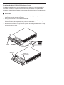
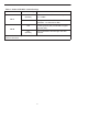
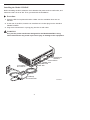
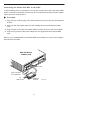
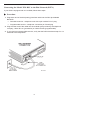
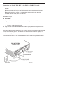
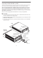
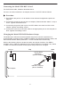
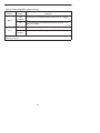
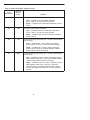
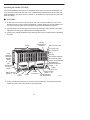
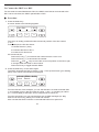
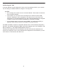
COMSPHERE
3550 SERIES
DATA SERVICE UNITS
MODELS 3550 AND 3551
QUICK REFERENCE
Document No. 3550-A2-GL10-10
Copyright 1999 Paradyne Corporation.
All rights reserved.
Printed in U.S.A.
Notice
This publication is protected by federal copyright law. No part of this publication may be
copied or distributed, transmitted, transcribed, stored in a retrieval system, or translated
into any human or computer language in any form or by any means, electronic,
mechanical, magnetic, manual or otherwise, or disclosed to third parties without the
express written permission of Paradyne Corporation, 8545 126th Ave. N., Largo,
FL 33773.
Paradyne Corporation makes no representation or warranties with respect to the
contents hereof and specifically disclaims any implied warranties of merchantability or
fitness for a particular purpose. Further, Paradyne Corporation reserves the right to
revise this publication and to make changes from time to time in the contents hereof
without obligation of Paradyne Corporation to notify any person of such revision or
changes.
Changes and enhancements to the product and to the information herein will be
documented and issued as a new release to this manual.
Warranty, Sales, Service, and Training Information
Contact your local sales representative, service representative, or distributor directly for
any help needed. For additional information concerning warranty, sales, service, repair,
installation, documentation, training, distributor locations, or Paradyne worldwide office
locations, use one of the following methods:
Internet: Visit the Paradyne World Wide Web site at www.paradyne.com. (Be
sure to register your warranty there. Select Service & Support → Warranty
Registration.)
Telephone: Call our automated system to receive current information by fax or to
speak with a company representative.
— Within the U.S.A., call 1-800-870-2221
— Outside the U.S.A, call 1-727-530-2340
Document Feedback
We welcome your comments and suggestions about this document. Please mail them
to Technical Publications, Paradyne Corporation, 8545 126th Ave. N., Largo, FL 33773,
or send e-mail to [email protected]. Include the number and title of this
document in your correspondence. Please include your name and phone number if you
are willing to provide additional clarification.
Trademarks
All products and services mentioned herein are the trademarks, service marks,
registered trademarks or registered service marks of their respective owners.
TM
COMSPHERE 3550 SERIES DATA SERVICE UNITS
MODELS 3550 AND 3551
Quick Reference
Document Number 3550-A2-GL10-10
March 1999
Product Documentation on the World Wide Web
We provide complete product documentation online. This lets you search the
documentation for specific topics and print only what you need, reducing the waste of
surplus printing. It also helps us maintain competitive prices for our products.
Complete documentation for this product is available at www.paradyne.com.
Select Library → Technical Manuals → Subrate Digital Access Devices.
Then select the following document:
3550-A2-GB20
COMSPHERE 3550 Series Data Service Units,
Models 3550 and 3551, User’s Guide
To request a paper copy of a Paradyne document:
Within the U.S.A., call 1-800-PARADYNE (1-800-727-2396)
Outside the U.S.A., call 1-727-530-8623
Installation
! HANDLING PRECAUTIONS FOR STATIC-SENSITIVE DEVICES
This product is designed to protect sensitive components from
damage due to electrostatic discharge (ESD) during normal
operation. When performing installation procedures,
however, take proper static control precautions to
prevent damage to equipment. If you are not sure
of the proper static control precautions, contact
your nearest sales or service representative.
496-15149
Before installing your DSU, read the Important Safety Instructions on page 23.
Be sure to register your warranty at www.paradyne.com. Select Service & Support →
Warranty Registration.
1
Changing the Model 3550 DSU Hardware Straps
The Model 3550 DSU has a switch located behind its diagnostic control panel (DCP).
This switch contains two straps, one that controls the permissive or programmable
connection when a DBM is installed, and one that controls the frame-to-signal grounds.
Table 1 shows the DSU’s settings.
Procedure
1. With your thumbs under the edge of the front bezel, firmly press upward to lift the
bezel from the tabs securing it in place.
2. Swing the front bezel up and set the bezel aside.
3. Refer to Table 1 to determine which switch needs to be changed. Then, using a
small instrument, carefully change the position of the switch.
4. Reinsert the front bezel’s hinge tabs into position and swing the bezel down. Snap
the bezel back into place.
FRONT BEZEL
E
ER
H
SP
M
O
C
50
35
SNAP
TABS
SWITCH 1
HINGE TAB
LOCATIONS
496-14457-01
2
Table 1. Model 3550 DSU Switch Settings
Switch Position
Switch Setting
Function
ON
(default)
Permissive V.32 DBM transmit output level
of –9 dBm
S1 1
S1-1
Off
Programmable V.32 DBM transmit level
between –12 dBm and 0 dBm
ON
Frame ground (FG) connected to signal
ground (SG)
Off
(default)
FG connected to SG through 100 ohm
resistor
S1 2
S1-2
ON is to the rear as you face the front of the DSU.
Off is to the front.
3
Installing the Model 3550 DSU
Before installing the DSU, label the circuit breaker that protects the ac wall outlet, and
make sure that it is set to ON. Then, proceed with the installation.
Procedure
1. Place the DSU in its planned location. Make sure the ventilation slots are not
blocked.
2. At the rear of the DSU, insert the ac transformer’s circular plug into the interface
labeled POWER.
3. Plug the ac transformer’s 3-prong plug into the ac wall outlet.
! WARNING:
Only use the power transformer designed for the Model 3550 DSU. Using
other transformers may result in personal injury or damage to the equipment.
EIA-232-D/V.24
Interface
V.35 Interface
NMS Jack
DBM Jack
DDS Jack
Low Voltage
AC Power In
Tabletop
AC Transformer
99-16243
4
Connecting the Model 3550 DSU to the NMS
A 3600 Hubbing Device is required to connect the control DSU to the 6700 Series NMS.
When connected to the NMS, the DSU can be controlled and configured from the NMS
rather than from the DCP alone.
Procedure
1. Plug the 4-pin modular plug of the 3600 Hubbing Device into the DSU jack labeled
CC/DC.
2. Plug one end of an M6BJ cable into the hubbing device jack labeled CC IN/DC
OUT.
3. Plug the other end of the 8-pin M6BJ cable into the 8-pin end of the 873A adapter.
4. Plug the D-type end of the 873A adapter into the appropriate 6700 Series NMS
jack.
Refer to your COMSPHERE 6700 Series NMS documentation to control and configure
the DSU from the NMS.
NMS NETWORK
CONNECTION
CC/DC
LOW VOLTAGE
AC POWER IN
TO
NMS (873A)
VICE
DE -300
ING 0-F3
BB
HU #300
00
30 ODEL
M
HUBBING
DEVICE
5
496-14576a
Connecting the Model 3550 DSU to the Dial Network (PSTN)
If your DSU is equipped with a V.32 DBM, follow these steps.
Procedure
1. Plug either end of the dial (analog) interface cable into the DSU jack labeled
BACKUP.
— Permissive service – telephone cord with 6-pin modular RJ11C plug
— Programmable service – telephone cord with 8-pin RJ45S plug
2. Plug the other end of the cable into the modular jack provided by the telephone
company, USOC RJ11C (permissive) or USOC RJ45S (programmable).
3. If your site has programmable service, verify that the DSU’s hardware strap S1-1 is
switched to the Off position.
6
Connecting the Model 3550 DSU to the DDS (or LADS) Network
NOTE:
Before connecting the DSU to the DDS network, ensure that approved primary
protectors have been installed on the circuit in accordance with Article 800 of the
National Electric Code, NFPA 70, in the United States and Section 60 of the
Canadian Electric Code, Part 1, in Canada.
Follow these steps.
Procedure
1. Plug the DDS network interface cable into the DSU jack labeled LINE.
— U.S. – select either end of the cable
— Canada – select the 8-pin end
2. Plug the other end of the cable into the modular jack (USOC RJ48S) provided by
the circuit provider.
If the remote DSU is also connected to the network, the DSU’s green OK indicator lights
and the Alrm indicator goes off. The Health and Status screen no longer displays a
No Signal message.
If connecting the DSU to a LADS network, note that there are distance limitations that
govern the use of DSUs on the network. See the User’s Guide for specific information.
7
Connecting the Model 3550 DSU to a DTE
The DSU’s rear panel has both a 25-pin EIA-232-D/V.24 connector and a 34-pin ITU-T
V.35 connector (used for higher operating speeds). You can use either interface.
When the unit is equipped with a TDM/Flex, either of these interfaces can be used as
Port 1. The TDM/Flex provides an additional interface to be used as Port 2. This is a
D-type connector. If the port is to operate at a speed greater than 19.2 kbps, use the
V.35 adapter to provide an interface between the TDM/Flex’s D-type connector and the
DTE cable’s V.35 connector.
Be sure to select the appropriate cable (EIA-232 or V.35) for your application.
Procedure
1. Connect the plug end of the DTE cable to Port 1, either the EIA-232-D or the V.35
connector. Tighten the two holding screws.
2. Connect the other end of the cable to the appropriate port on the computer or DTE.
Tighten any holding screws.
3. If necessary, activate the port to match the interface: EIA-232 or V.35. The default
setting is EIA-232.
DSU
EIA-232-D/V.24
Interface
V.35
Interface
DSU with
TDM/FLEX
To DTE
EIA-232-D/V.24
Interface (Port 1)
Low Voltage
AC Power In
EIA-232
Interface
(Port 2)
V.35 Interface
(Port 1)
V.35 Adapter
V.35 Cable
To DTE
99-16299
8
Connecting the Model 3550 DSU’s Port 2
For the EIA-232 cable, install as described above.
For the V.35 cable, install the V.35 adapter, then the V.35 DTE cable as follows.
Procedure
1. Reconfigure the port for a V.35 interface. See General Configuration Options on
page 21.
2. Connect the 25-pin plug end of the V.35 adapter (Feature Number 3000-F1-510) to
Port 2. Tighten the thumbscrews.
3. Connect the plug end of the 34-pin V.35 DTE cable to the other end of the V.35
adapter. Tighten the holding screws.
4. Connect the other end of the DTE cable to the appropriate port on the computer or
DTE. Tighten the holding screws.
Changing the Model 3551 DSU Hardware Straps
The Model 3551 DSU has several hardware straps that control the permissive or
programmable connection when a DBM is installed, the Test Mode Indication leads, and
the external interface leads (used with a – 48 Vdc Central Office Power Unit).
Refer to the following figure to locate the switch and jumper locations. If a DBM is
installed, refer to Table 2 to determine which switch needs to be changed, if any. Refer
to Table 3 to determine whether these jumper straps need to be changed.
Switch 1
Top
Rear
–48 Vdc Alarm
Monitoring
(Shown Disabled)
J20
J21
J13
J12
Test Mode
Indication Jumpers
(Shown Enabled)
Faceplate
P7
99-16245
9
Table 2. Model 3551 DSU Switch Settings
Switch
Position
Switch
Setting
Function
ON
(default)
Permissive V.32 DBM transmit output level of –9 dBm
Off
Programmable V.32 DBM transmit level between –12
dBm and 0 dBm
ON
Frame ground (FG) connected to signal ground (SG)
S1 1
S1-1
S1-2
Off
(default)
FG connected to SG through 100 ohm resistor
ON is to the rear as you face the front of the DSU.
Off is to the front.
10
Table 3. Model 3551 DSU Jumper Straps
Strap
Designation
State of
Jumper
Strap
J12
Left
Function
V.35 Test Mode Indication:
Left — Enables V.35 Test Mode Indication
(Pins 1 and 2). This is the factory default.
Right — Disables V.35 Test Mode Indication (Pins 2
and 3).
J13
Left
EIA-232-D Test Mode Indication:
Left — Enables EIA-232-D Test Mode Indication
(Pins 1 and 2). This is the factory default.
Right — Disables EIA-232-D Test Mode Indication
(Pins 2 and 3).
J20
Left
Alarm Monitoring (used with the – 48 Vdc Central Office
Power Unit):
Left — Disables the – 48 Vdc alarm monitoring
function (Pins 1 and 2). This is the factory default.
Right — Enables the – 48 Vdc alarm monitoring
function (Pins 2 and 3); the NMS adapter cable is
being used for alarm monitoring.
J21
Right
Alarm Monitoring (used with the – 48 Vdc Central Office
Power Unit):
Left — Enables control of alarm monitoring via the
NMS adapter cable (Pins 1 and 2); the NMS adapter
cable is being used for alarm monitoring.
Right — Disables control of alarm monitoring via the
NMS adapter cable (Pins 2 and 3); a standard
EIA-232 cable or the NMS adapter cable is being
used for the diagnostic channel. This is the factory
default.
11
Installing the Model 3551 DSU
The initial installation procedure for the Model 3551 DSU requires the installation of a
rear connector plate onto the rear of the COMSPHERE 3000 Series Carrier. After the
initial installation, the DSU can be installed or uninstalled by simply removing the DSU
from the carrier.
Procedure
1. At the rear of the carrier, set the tab on the rear connector plate into one of the
slotted grooves on the carrier’s backplane. Loosely fasten the screws. Make sure
the rear connector plate uses the same slot position intended for the DSU.
2. Loosely fasten the screw attached to the rear connector plate, allowing for slight
adjustment that may be needed when installing the DSU.
3. Change any default hardware strap settings that may be required before installing
the DSU.
25-Pin
EIA-232/V.24
Interface
DSUs
CC In/DC Out
CC Out/DC In
FP In
FP Out
S2-Carrier Address
S1-Protocol Strap
Dial
Network
Interface
Module
(Slots
9 – 16)
25-Pin V.35 Interface
Dial Network
Interface Module
(Slots 1 – 8)
Not
Supported
For 3551
DSUs
DDS Interface
(Slots 9 – 16)
SDU Circuit Card
AC
Power
Fuses
Alarm
E1 & E2
DDS Interface
Power
(Slots 1 – 8)
Connectors
Not Supported
For 3551 DSUs
99-16246
4. Using a Phillips screwdriver, loosen the screw holding the circuit pack lock and
rotate the lock to the open position. Open the latch.
12
5. At the front of the carrier, hold the DSU vertically with the latch on its faceplate in
the open position. Then, insert the circuit card into the top and bottom circuit card
guides for the slot that contains the rear connector plate.
Slide the DSU into the slot, aligning the circuit card with the rear connector plate
until the connectors seat firmly into the back of the carrier. Press the faceplate latch
to secure the DSU into the carrier, rotate the circuit pack lock into the closed
position, and tighten the screw.
6. Return to the rear of the carrier and tighten the rear connector plate screw.
13
7. At the rear of the carrier, connect the appropriate DTE interface cable (EIA-232-D
or V.35) to the rear connector plate. For an EIA-232-D interface cable, connect the
EIA-232-D cable to the top DTE connector on the rear connector plate.
For the 25-pin V.35 interface, a V.35 adapter is shipped with the unit. To connect a
V.35 adapter to the 25-pin V.35 connector, perform the following steps:
— Connect the 25-pin end of the V.35 adapter to the bottom DTE connector of
the rear connector plate. Tighten the thumbscrews on each side of the
connector.
— Connect the V.35 interface cable to the 34-pin end of the V.35 adapter, then
tighten the screws on each side of the cable connector.
25-Pin Connector
Thumbscrews
V.35 Adapter
V.35 Cable
99-16298
8. The installed DSU is connected to the DDS network through the 50-pin connectors
at the rear of the carrier. These interfaces are specified in the USOC RJ48T, and
the pin assignments are shown in Appendix D of the User’s Guide. Proper network
connection to the DDS facility or to the network channel-terminating equipment
must be made at the far end of the cable.
9. If the network line and remote DSU are installed and tested, do a Remote
Loopback – a Test Pattern test.
10. If the Front Panel test switch strap is to be disabled, slide the DSU slightly out of
the carrier, open Switch S3-1, then reseat the DSU into the carrier. Do this now.
11. Circuit ID information can be written on the cover plate under the appropriate slot
number.
14
Connecting the Model 3551 DSU to the NMS
A Model 3551 DSU is set up for network diagnostic connection through the shared
diagnostic unit (SDU), which is installed in Slot 0 of the carrier. Refer to the
COMSPHERE 3000 Series Carrier Installation Manual, Document No. 3000-A2-GA31,
to set up the network diagnostic connection.
For connection of the DSU, or for pin assignments, see the User’s Guide.
Connecting the Model 3551 DSU to the Dial Network (PSTN)
Connection to the dial network (or public switched telephone network) for the
carrier-mounted Model 3551 DSU is through a network interface module (NIM) that is
installed onto the carrier’s backplane. Refer to the COMSPHERE 3000 Series Carrier
Installation Manual for additional information or to install the NIM.
Connecting the Model 3551 DSU to the DDS (or LADS) Network
NOTE:
Before connecting the DSU to the DDS network, ensure that approved primary
protectors have been installed on the circuit in accordance with Article 800 of the
National Electric Code, NFPA 70, in the United States and Section 60 of the
Canadian Electric Code, Part 1, in Canada.
If connecting the DSU to a LADS network there are distance limitations that govern the
use of DSUs on the network. See the User’s Guide for specific information.
The DDS network interface is provided by two RJ48T 50-pin connectors on the back of
the carrier. Each connector serves eight contiguous slots in the carrier: one for Slots 1
through 8 and one for Slots 9 through 16.
Connecting the Model 3551 DSU to a DTE
The DTE interface for the Model 3551 DSU is provided through its rear connector plate.
Each rear connector plate contains two DB25 (or 25-pin D-type) connectors. The top
connector is an EIA-232-D/V.24 (ISO 2110) connector. The bottom connector is an
ITU-T V.35 (ISO 2593) connector.
To use the 25-pin V.35 connector (used for speeds greater than 19.2 kbps), a V.35
adapter is needed (Feature Number 3000-F1-510). The adapter provides the interface
between the 25-pin V.35 D-type connector and a V.35 DTE cable.
Each DSU can be configured to use either interface (EIA-232 or V.35) independent of
other DSUs in the carrier. Connection of the DSU to the DTE is a matter of selecting
and installing the appropriate cable. Refer to the COMSPHERE 3000 Series Carrier
Installation Manual for installation procedures.
15
To Connect the SDCP to a DSU
For the carrier-mounted Model 3551 DSU, the SDCP must first be reconnected to the
DSU. Once connected, the SDCP operates like a DCP.
Procedure
1. Press the Select key.
A screen similar to the following appears.
Carr:Slot:
F1
1: 01 A
1:0 2 A
F2
F3
The cursor is usually positioned under the second position of the slot number
(1: 0 1 ).
In this example, the first line shows:
1 indicates Carrier 1 (Carr)
01 indicates the DSU in Slot 1
A is reserved for future use
On the second line:
Press the F1 key ( ↑ ) to increment the number that the cursor is on.
Press the F2 key ( ↓ ) to decrement the number.
Press the
and
keys to move the cursor one position to the left or right,
to change either the carrier or slot number.
Press the F3 key to toggle between DSUs.
2. Press the Select key on the SDCP again.
The SDCP accesses the DSU in Carrier 1, Slot 1. The top-level menu (your starting
point) of the carrier-mounted DSU is displayed.
1: 01 A DSU
Local Remot
F1
F2
9.6 C
F3
From the first line of this example, you can see that this is a carrier-mounted DSU
(1:01A instead of Port1) that is located in Carrier 1, Slot 1, is operating as a DSU
(i.e., not as a DBM), at 9.6 kbps, and is configured as a control (C).
From the second line you can see that there are no NMS messages (no Msg
branch over the F3 key) waiting to be read and cleared.
Also note that the SDCP indicator on the selected DSU’s front panel is lit.
16
Addressing the Unit
A unique address must be assigned to each control and tributary DSU in your network.
You can assign an address within the range of 1 through 255.
NOTES:
— Do not assign the number 192 as a network address. This number is reserved
as a broadcast address.
— The numbers 191 and 255 cannot be assigned to a DSU that has a DBM.
However, addresses can be assigned in any order; they do not have to be
sequential. It is recommended that only odd-numbered addresses be assigned
to DSUs so that even-numbered addresses are reserved for DBMs.
— If your network does not currently include DBMs, you retain the flexibility to
add them later without having to reconfigure your entire network.
If a DBM is installed, it requires a separate address which is automatically assigned by
the DSU. The address assigned a DBM is the DSU’s address, plus 1 (for example, if the
DSU’s address is 1, the assigned DBM address will be 2).
Tributary DSU addresses are user-definable, but take care that their addresses are
unique on a multipoint circuit. If two tributaries are assigned the same address, you will
not be able to communicate with either one.
17
Power-Up Routine
When power is applied, the DSU:
H
Determines what options (DBM or TDM/Flex) are installed, if any.
H
Runs a Device Test on itself and each of the installed options.
During the tests, all indicators on the DCP light briefly and the message Power-Up
Tests appears on the liquid crystal display (LCD).
H
Displays the results of each test momentarily as Pass, Fail, or Abrt. (Abrt indicates
that the Device Test was aborted because a network loopback was in progress
during the power-up procedure.) These tests take about 20 seconds to complete.
If a TDM/Flex is installed, MUX is displayed as Pass or Fail.
If the DSU or DBM fails this test, follow the procedure below.
" Procedure
1. Press the
key to return to the top-level menu.
2. Select Local (F1 key).
3. Press the
key to scroll the Confg (Configuration) branch into view.
4. Press the function key directly below Confg.
5. Press the F1 key to select Opts (Configuration Options).
The Load from screen appears.
6. Press the
key to bring the factory-loaded unit configurations into view, and
select the appropriate configuration.
— PTPC for a point-to-point control
— PTPT for a point-to-point tributary
— MPTC for a multipoint control
— MPTT for a multipoint tributary
7. Press the F1 key to SAVE the selected configuration.
The Save to screen appears.
8. Save the selected configuration to Activ (F1 key).
9. Press the
key to return to the top-level menu, then select Local again.
10. Select the Test branch (F3).
The Run Test on screen appears.
11. Select the device that Failed: the DSU (or the TDM/Flex) or DBM.
12. Press the F2 key to run the Device Test again.
The device should pass.
13. Should the device fail, contact your service representative.
18
Configuration Options
Configuration options are accessed from the Configuration branch of the front panel
menu.
In the following tables, factory defaults are shown in boldface. If they differ from each
other, defaults are shown for PTPC, PTPT, MPTC, and MPTT.
Key to symbols:
These configuration options do not appear when Full mode is disabled using
Menu from the Configuration branch.
Menu
Full Mode
DSU
Configuration Options
Rate(Kbps)
PrtSp(Kbps)
TxClkSource
Msg Clamp
TxElasStor
RxElasStor
19.2 PowrLvl
V.54 Lpbk
Value
Enab, Disab
Value
64L, 56, 38.4, 19.2, 9.6, 4.8, 2.4
64, 56, 48, 19.2, 9.6, 4.8, 2.4 , 1.2, Disab
Int, Ext, Prt1, Prt2, DDS
Enab, Disab
Enab, Disab
Enab, Disab
+ 6, 0, –10
Enab, Disab
Diagnostic DSU
Configuration Options
Diag Type
NonD, Disr, Mixed, None
2nd Ch(bps)
100, 400, 800, 1200, 1600
Diagnostic DBM
Configuration Options
Diag Type
NonD, Disr, Mixed, None
2nd Ch(bps)
100, 400, 800, 1200, 1600
Diagnostic External
DBU Configuration
Options
Diag Type
Value
Value
Value
Disr, None
19
Diagnostic General
Configuration Options
Position
LinkConfg
Resp Period
TribTimOut
Link Delay
Packet Delay
M-PtSymPrt
Value
Cntrl (PTPC, MPTC), Trib (PTPT, MPTT)
Pt-Pt (PTPC, PTPT), M-Pt (MPTC, MPTT)
1, 2, 10
0:10
(5 sec to 10 min)
0s, 1s, 2s, 5s, 10s, 20s, 50s
0s, 1s, 2s, 5s
Enab, Disab
DBM
Configuration Options
Value
Rate(Kbps)
14.4, 12.0, 9.6, 4.8, 2.4
PrtSp(Kbps)
14.4, 12.0, 9.6, 4.8, 2.4, 1.2, Disab
TxClkSource
Int (PTPC, MPTC), RXC (PTPT, MPTT), Ext, Prt1, Prt2, DSU
CarrLossDisc
Yes, No
Auto Retrain
Yes, No
Single Rate
AutoAnswer
Yes, No
TxElasStor
RxElasStor
Enab, Disab
Enab, Disab
Enab, Disab
Call Setup
None, Pswrd, Cllbk, Alarm
RxPwd
(10 characters)
TxPwd
(10 characters)
V.13 Signl
Dial Test
Enab (MPTC, MPTT), Disab (PTPC, PTPT)
DtrCallCon
Enab, Disab
Ansr, Disab
External DBU
Configuration Options
ExtBU
Rate(Kbps)
TxClkSource
Value
Ansr, Orig, None
64, 56, 38.4, 28.8, 19.2, 14.4, 9.6, 4.8, 2.4, 1.2, Disab
DCE, Prt1, Prt2
20
General
Configuration Options
DTE Port
RTS Cntrl
CTS Cntrl
AntiStream
LSD Lead
DSR FrcOn
SystemStat
DSR on Tst
Circ Assur
RespondRDL
LL by DTE
RL by DTE
Bilat Lpbk
Ext Leads
CCN by EL
DTR Alarm
Async→Sync
AsyncBit/Char
Stop Bits
Overspeed
Value
EIA232, V.35
FrcOn (PTPC, PTPT, MPTC), DTE (MPTT)
Std, = RTS, Delay, FrcOn
Disab, 1 – 100 sec
Std, Delay, FrcOn
Enab, Disab
Enab, Disab
Enab, Disab
Enab, Disab
Enab (PTPC, PTPT, MPTT), Disab (MPTC)
Enab, Disab
Enab, Disab
Enab, Disab
ExtLd, Rate, RPowr
Enab, Disab
Enab, Disab
Enab, Disab
6, 7, 8, 9, 10
1, 2
1.0, 2.3
Backup
Configuration Options
Auto Bckup
Enab, Disab
Backup Dir
FacAlOnCMI
Value
1–10
Enab, Disab
AutoRestor
Enab, Disab
NtwkTimOut
1:00 (PTPC, MPTC), 0:20 (PTPT, MPTT) (1 sec to 30 min)
RestorTimOut
5 min (1 min to 60 min)
TriesTimeOut
15 min (1 min to 60 min)
MultiCall
Enab, Disab
MUX Setup
Configuration Options
MUX Funct
Share DevA
Port Cntrl
Value
TDM, MCMP, CBrdg, EBrdg, None
Enab, Disab
Host, DSD
21
MUX Port
Configuration Options
DTE Port
Async→Sync
Async Rate
AsyncBit/Char
Stop Bits
Overspeed
RTS Cntrl
TxCarrSel
RxCarrSel
PCC Buffer
Elast Stor
RTS/CTS Del
DTR Alarm
AntiStream
DSR FrcOn
DSR on Tst
Value
EIA232, V.35
Enab, Disab
=Sync, 1800, 1200, 600, 300, 150
6, 7, 8, 9, 10
1, 2
1.25, 2.5
FrcOn, DTE
Const, Cntrl
Const, Cntrl, Mark
Enab, Disab
Enab, Disab
0–1040 ms (8 ms increments)
Enab, Disab
Disab, 1–100 sec
Enab, Disab
Enab, Disab
Port Speed (DSU)
Configuration Options
Value
Prt1 (9.6)
64, 56, 48, 19.2, 9.6, 4.8, 2.4, 1.2, Disab
Prt2 (9.6)
64, 56, 48, 19.2, 9.6, 4.8, 2.4, 1.2, Disab
Underspeed
Disab, Prt1, Prt2
Port Speed (DBM)
Configuration Options
Value
Prt1 (9.6)
14.4, 12.0, 9.6, 4.8, 2.4, 1.2, Disab
Prt2 (9.6)
14.4, 12.0, 9.6 (MPTT), 4.8, 2.4, 1.2, Disab (PTPC, PTPT, MPTC)
Underspeed
Disab, Prt1, Prt2
Port Speed
(External DBU)
Configuration Options
Value
Prt1 (9.6)
64, 56, 48, 28.8, 19.2, 14.4, 9.6, 4.8, 2.4, 1.2, Disab
Prt2 (9.6)
64, 56, 48, 28.8, 19.2, 14.4, 9.6, 4.8, 2.4, 1.2, Disab
Underspeed
Disab, Prt1, Prt2
22
!
Important Safety Instructions
1. Read and follow all warning notices and instructions marked on the product or
included in the manual.
2. This product is intended to be used with a 3-wire grounding type plug – a plug
which has a grounding pin. This is a safety feature. Equipment grounding is vital to
ensure safe operation. Do not defeat the purpose of the grounding type plug by
modifying the plug or using an adapter.
Prior to installation, use an outlet tester or a voltmeter to check the ac receptacle
for the presence of earth ground. If the receptacle is not properly grounded, the
installation must not continue until a qualified electrician has corrected the problem.
If a 3-wire grounding type power source is not available, consult a qualified
electrician to determine another method of grounding the equipment.
3. Slots and openings in the cabinet are provided for ventilation. To ensure reliable
operation of the product and to protect it from overheating, these slots and
openings must not be blocked or covered.
4. Do not allow anything to rest on the power cord and do not locate the product
where persons will walk on the power cord.
5. Do not attempt to service this product yourself, as opening or removing covers may
expose you to dangerous high voltage points or other risks. Refer all servicing to
qualified service personnel.
6. General purpose cables are provided with this product. Special cables, which may
be required by the regulatory inspection authority for the installation site, are the
responsibility of the customer.
7. When installed in the final configuration, the product must comply with the
applicable Safety Standards and regulatory requirements of the country in which it
is installed. If necessary, consult with the appropriate regulatory agencies and
inspection authorities to ensure compliance.
8. A rare phenomenon can create a voltage potential between the earth grounds of
two or more buildings. If products installed in separate buildings are
interconnected, the voltage potential may cause a hazardous condition. Consult a
qualified electrical consultant to determine whether or not this phenomenon exists
and, if necessary, implement corrective action prior to interconnecting the products.
9. In addition, if the equipment is to be used with telecommunications circuits, take the
following precautions:
— Never install telephone wiring during a lightning storm.
— Never install telephone jacks in wet locations unless the jack is specifically
designed for wet locations.
— Never touch uninsulated telephone wires or terminals unless the telephone line
has been disconnected at the network interface.
— Use caution when installing or modifying telephone lines.
— Avoid using a telephone (other than a cordless type) during an electrical storm.
There may be a remote risk of electric shock from lightning.
— Do not use the telephone to report a gas leak in the vicinity of the leak.
23
Notices
! WARNING:
! WARNING:
!
Government Requirements
The Federal Communications Commission (FCC) requires that instructions pertaining to
connection to the telephone network be included in the installation and operation
manual. Specific instructions are listed in this section.
Notice to Users of the Digital Data Service
This equipment complies with Part 68 of the FCC rules. On the bottom of the equipment
is a label or silkscreened text that contains, among other information, the FCC
registration number and Ringer Equivalence Number (REN) for this equipment. If
requested, please provide this information to your telephone company.
The REN is useful to determine the quantity of devices you may connect to your
telephone line and still have all of those devices ring when your number is called. In
most, but not all areas, the sum of the RENs of all devices should not exceed 5. To be
certain of the number of devices you may connect to your line, as determined by the
REN, you should call your local telephone company to ascertain the maximum REN for
your calling area.
24
If your DSU causes harm to the telephone network, the telephone company may
discontinue your service temporarily. If possible, they will notify you in advance. But if
advance notice is not practical, you will be notified as soon as possible. You will be
advised of your right to file a complaint with the FCC.
Your telephone company may make changes in its facilities, equipment, operations, or
procedures that could affect the proper operation of your equipment. If so, you will be
given advance notice so as to give you an opportunity to maintain uninterrupted
service.
The DBM cannot be used on public coin-operated telephone service provided by the
telephone company. Connection to party-line service is subject to state tariffs. (Contact
the state public utility commission, public service commission, or corporation
commission for information.)
No repairs may be performed by the user. Should you experience difficulty with this
equipment, refer to the Warranty, Sales, Service and Training Information in the front of
this document.
For Digital Data Service (DDS) installations, inform the local telephone company of the
appropriate network channel interface code for the service you desire.
Interface
Code
Data Rate
(bps)
04DU5-24
2400
04DU5-48
4800
04DU5-96
9600
04DU5-19
19,200
04DU5-56
56,000
The DDS Service Order Number is 6.0Y. The jack configurations required are RJ48S for
the Model 3550 DSU and RJ48T for the Model 3551. With an RJ48T configuration, you
must specify the number of data lines you require. Refer to Technical Specifications in
the User’s Guide for V.32 DBM jack information.
After the telephone company has installed the requested jack, you can connect the
DSU with the appropriate cable (provided). An FCC-compliant telephone cord and
modular plug is provided with this equipment. This equipment is designed to be
connected to the telephone network or premises wiring using a compatible modular jack
that is Part 68 compliant.
25