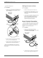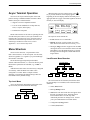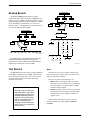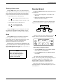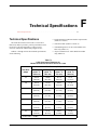
1
COMSPHERE
3600 SERIES
DATA SERVICE UNITS
MODELS 3610 AND 3611
USER’S GUIDE
Document No. 3610-A2-GB46-60
December 1996
NOTE
This document supports Firmware version 8.0 or greater.
Refer to Appendix G for Firmware Version Control
Information.
COMSPHERE 3600 Series Data Service Units
COMSPHERE
3600 Series Data Service Units
Models 3610 and 3611
User’s Guide
3610-A2-GB46-60
7th Edition (December 1996)
Changes and enhancements to the product and to the information herein will be documented and issued as a new release.
United States
FCC Registration number: AW292J-61661-DD-N
PSTN Ringer Equivalence number (REN) V.32 DBM option 0.7B
Canada
V.32 Dial Backup Module
Certification number: 230 3684 A
DOC Load number: 7
2-Wire Switched 56 DBM
Certification number: 230 5870 A
DOC Load number: 0
ISDN Dial Backup Module
Certification number: 230 6943 A
DOC Load number: 0
Warranty, Sales, and Service Information
Contact your sales or service representative directly for any help needed. For additional information concerning warranty, sales,
service, repair, installation, documentation, or training, use one of the following methods:
• Via the Internet: Visit the Paradyne World Wide Web site at http://www.paradyne.com
• Via Telephone: Call our automated call system to receive current information via fax or to speak with a company representative.
— Within the U.S.A., call 1-800-870-2221
— International, call 813-530-2340
Trademarks
All products and services mentioned herein are the trademarks, service marks, registered trademarks or registered service marks of their
respective owners.
Printed on recycled paper
COPYRIGHT E 1996 Paradyne Corporation. All rights reserved.
This publication is protected by federal copyright law. No part of this publication may be copied or distributed, transmitted, transcribed, stored in a retrieval system,
or translated into any human or computer language in any form or by any means, electronic, mechanical, magnetic, manual or otherwise, or disclosed to third parties
without the express written permission of Paradyne Corporation, 8545 126th Avenue North, P.O. Box 2826, Largo, Florida 33779-2826.
Paradyne Corporation makes no representation or warranties with respect to the contents hereof and specifically disclaims any implied warranties of merchantability
or fitness for a particular purpose. Further, Paradyne Corporation reserves the right to revise this publication and to make changes from time to time in the contents
hereof without obligation of Paradyne Corporation to notify any person of such revision or changes.
A
December 1996
3610-A2-GB46-60
Safety Instructions
Important Safety Instructions
1. Read and follow all warning notices and instructions marked on the product or included in the
manual.
2. This product is intended to be used with a three-wire grounding type plug – a plug which has a
grounding pin. This is a safety feature. Equipment grounding is vital to ensure safe operation. Do
not defeat the purpose of the grounding type plug by modifying the plug or using an adapter.
Prior to installation, use an outlet tester or a voltmeter to check the ac receptacle for the presence of
earth ground. If the receptacle is not properly grounded, the installation must not continue until a
qualified electrician has corrected the problem.
If a three-wire grounding type power source is not available, consult a qualified electrician to
determine another method of grounding the equipment.
3. Slots and openings in the cabinet are provided for ventilation. To ensure reliable operation of the
product and to protect it from overheating, these slots and openings must not be blocked or covered.
4. Do not allow anything to rest on the power cord and do not locate the product where persons will
walk on the power cord.
5. Do not attempt to service this product yourself, as opening or removing covers may expose you to
dangerous high voltage points or other risks. Refer all servicing to qualified service personnel.
6. General purpose cables are provided with this product. Special cables, which may be required by the
regulatory inspection authority for the installation site, are the responsibility of the customer.
7. When installed in the final configuration, the product must comply with the applicable Safety
Standards and regulatory requirements of the country in which it is installed. If necessary, consult
with the appropriate regulatory agencies and inspection authorities to ensure compliance.
8. A rare phenomenon can create a voltage potential between the earth grounds of two or more
buildings. If products installed in separate buildings are interconnected, the voltage potential may
cause a hazardous condition. Consult a qualified electrical consultant to determine whether or not
this phenomenon exists and, if necessary, implement corrective action prior to interconnecting the
products.
9. In addition, if the equipment is to be used with telecommunications circuits, take the following
precautions:
— Never install telephone wiring during a lightning storm.
— Never install telephone jacks in wet locations unless the jack is specifically designed for wet
locations.
— Never touch uninsulated telephone wires or terminals unless the telephone line has been
disconnected at the network interface.
— Use caution when installing or modifying telephone lines.
— Avoid using a telephone (other than a cordless type) during an electrical storm. There may be a
remote risk of electric shock from lightning.
— Do not use the telephone to report a gas leak in the vicinity of the leak.
3610-A2-GB46-60
December 1996
B
COMSPHERE 3600 Series Data Service Units
Notices
Government Requirements
Certain governments require that instructions pertaining to connection to the telephone network be
included in the installation and operation manual. Specific instructions are listed in the following
sections.
United States
Notice to Users of the Telephone Network
This equipment complies with Part 68 of the FCC rules. On the bottom of the equipment is a label
or silk-screened text that contains, among other information, the FCC registration number and
Ringer Equivalence Number (REN) for this equipment. If requested, please provide this
information to your telephone company.
The REN is useful to determine the quantity of devices you may connect to your telephone line
and still have all of those devices ring when your number is called. In most areas, the sum of the
RENs of all devices should not exceed 5. Call your local telephone company to ascertain the
maximum REN for your calling area.
If your Model 3610 or 3611 DSU with DBM causes harm to the telephone network, the telephone
company may discontinue your service temporarily. If possible, they will notify you in advance.
But if advance notice is not practical, you will be notified as soon as possible. You will be advised
of your right to file a complaint with the FCC.
Your telephone company may make changes in facilities, equipment, operations, or procedures that
could affect the proper operation of your equipment. If so, you will be given advance notice so as
to give you an opportunity to maintain uninterrupted service.
C
December 1996
3610-A2-GB46-60
Safety Instructions
The DBM cannot be used on public coin-operated telephone service provided by the telephone
company. Connection to party-line service is subject to state tariffs. Contact the state public utility
commission, public service commission, or corporation commission for information.
No repairs may be performed by the user. Should you experience difficulty with this equipment,
refer to the Equipment Warranty and Support section.
For Digital Data Service (DDS) installations, inform the local telephone company of the
appropriate facility interface code for the service you desire.
DDS Facility
Interface
Code
Data Rate
(bps)
Interface
Code
Data Rate
(bps)
04DU5-24
2400
04DU5-38
38,400
04DU5-48
4800
04DU5-56
56,000
04DU5-96
9600
04DU5-64
64,000
04DU5-19
19,200
For DBM installations, the proper service and jack must be ordered from the telephone company.
Refer to the following table for this information.
DBM Jack Installation Requirements
DBM Type
USOC Jack
(Standalone)
USOC Jack
(Carrier-Mounted)
Canadian Jack
(Standalone)
Canadian Jack
(Carrier-Mounted)
12.0 or 14.4 kbps
V.32bis DBM
RJ11C Permissive
RJ45C Programmable
RJ21X Permissive
RJ27X Programmable
CA11A Permissive
CA27A Programmable
CA21A Permissive
CA27A Programmable
2-Wire Switched
56 DBM
SJA48
SJA48 (uses an
adapter cable)
CA11
(metallic channel)
CA21A
(metallic channel)
4-Wire Switched
56 DBM
SJA56
SJA57
Not available
in Canada
Not available
in Canada
ISDN BRI DBM
SJA11
SJA11 (uses an
adapter cable)
CA-A11
CA-A11 (uses an
adapter cable)
After the telephone company has installed the requested service and jack, you can connect the
DSU with the cable provided. An FCC-compliant telephone cord and modular plug are provided
with this equipment. This equipment is designed to be connected to the telephone network or
premises wiring using a compatible modular jack that is Part 68 compliant.
3610-A2-GB46-60
December 1996
D
COMSPHERE 3600 Series Data Service Units
Canada
Notice to Users of the Canadian Telephone Network
The Canadian Department of Communications has certified that this equipment meets certain
telecommunications network protective, operational, and safety requirements. The Department
does not guarantee that the equipment will operate to the user’s satisfaction.
Before installation, verify connectivity of this equipment to the local telecommunications
company’s facilities. The equipment must be connected by an acceptable method. In some cases,
the telecommunications company’s inside wiring associated with single-line individual service
may be extended with a certified connector assembly (telephone connection cord). The customer
should be aware that compliance with the above conditions may not prevent degradation of service
in some situations.
If you experience difficulty with this equipment and require service, refer to the Equipment
Warranty and Support section.
Repairs to certified equipment should be made by an authorized Canadian maintenance facility.
Any repairs or alterations made by the user to this equipment, or equipment malfunctions, may
cause the telecommunications company to ask you to disconnect the equipment.
Users should ensure that the electrical ground connections of the power utility, telephone lines and
internal metallic water pipe system, if present, are connected together for protection. This
precaution may be particularly important in rural areas.
CAUTION
Users should not attempt to make such connections themselves,
but should contact the appropriate electric inspection authority,
or an electrician, as appropriate.
The load number (LN) is labeled on the equipment. The LN denotes the percentage of the total
load to be connected to a telephone loop used by this equipment. To prevent an overload, the total
of the LNs of all devices attached to the loop may not exceed 100. The LN also specifies the
appropriate ringing type (A or B), if applicable. For example, LN = 20A designates a load number
of 20 and an A type ringer.
Equipment Warranty and Support
If you experience trouble with this equipment, please contact your sales or service representative
(as appropriate) for repair or warranty information. If the product needs to be returned to the
company service center for repair, contact them directly for return instructions using one of the
following methods:
• Via the Internet: Visit the Paradyne World Wide Web site at http://www.paradyne.com
• Via Telephone: Call our automated call system to receive current information via fax or to
speak with a company representative.
— Within the U.S.A., call 1-800-870-2221
— International, call 813-530-2340
If the trouble is causing harm to the telephone network, the telephone company may request that
you remove the equipment from the network until the problem is resolved.
E
December 1996
3610-A2-GB46-60
Table of Contents
Preface
About This Guide . . . . . . . . . . . . . . . . . . . . . . . . . . . . . . . . . . . . . . . . v
How to Use This Guide . . . . . . . . . . . . . . . . . . . . . . . . . . . . . . . . . . . v
Related Documents . . . . . . . . . . . . . . . . . . . . . . . . . . . . . . . . . . . . . . v
1. Product Introduction
Standard DSU Features . . . . . . . . . . . . . . . . . . . . . . . . . . . . . . . . . . .
Optional DSU Features . . . . . . . . . . . . . . . . . . . . . . . . . . . . . . . . . . .
DBM Common Capabilities . . . . . . . . . . . . . . . . . . . . . . . . . . . . .
TDM/MCMP and Digital Bridge Capabilities . . . . . . . . . . . . . . .
Related Documents . . . . . . . . . . . . . . . . . . . . . . . . . . . . . . . . . . . . . .
1-1
1-2
1-3
1-4
1-5
2. Model 3610 Installation
Overview . . . . . . . . . . . . . . . . . . . . . . . . . . . . . . . . . . . . . . . . . . . . . .
Before You Begin . . . . . . . . . . . . . . . . . . . . . . . . . . . . . . . . . . . . . . . .
Installation Process . . . . . . . . . . . . . . . . . . . . . . . . . . . . . . . . . . . .
DSU Installation Planning . . . . . . . . . . . . . . . . . . . . . . . . . . . . . . .
Verifying the S1 Switch Settings . . . . . . . . . . . . . . . . . . . . . . . . . . . .
Powering Up the DSU . . . . . . . . . . . . . . . . . . . . . . . . . . . . . . . . . . . .
Power-Up Routine . . . . . . . . . . . . . . . . . . . . . . . . . . . . . . . . . . . . .
Saving and Changing Configuration Options . . . . . . . . . . . . . . . . . .
Home Screen Display . . . . . . . . . . . . . . . . . . . . . . . . . . . . . . . . . .
DDS Network Connection . . . . . . . . . . . . . . . . . . . . . . . . . . . . . . . . .
Network Verification Testing . . . . . . . . . . . . . . . . . . . . . . . . . . . . . . .
DTE Connections . . . . . . . . . . . . . . . . . . . . . . . . . . . . . . . . . . . . . . . .
Network Diagnostic Connection . . . . . . . . . . . . . . . . . . . . . . . . . . . .
SNA Diagnostic Interface Verification . . . . . . . . . . . . . . . . . . . . .
Async Terminal Connection . . . . . . . . . . . . . . . . . . . . . . . . . . . . . . . .
3610-A2-GB46-60
December 1996
2-1
2-1
2-2
2-2
2-2
2-4
2-4
2-5
2-6
2-8
2-8
2-9
2-9
2-10
2-10
i
COMSPHERE 3600 Series Data Service Units
3. Front Panel Operation
Overview . . . . . . . . . . . . . . . . . . . . . . . . . . . . . . . . . . . . . . . . . . . . . .
Front Panels . . . . . . . . . . . . . . . . . . . . . . . . . . . . . . . . . . . . . . . . . . . .
LCD . . . . . . . . . . . . . . . . . . . . . . . . . . . . . . . . . . . . . . . . . . . . . . . .
Keypad . . . . . . . . . . . . . . . . . . . . . . . . . . . . . . . . . . . . . . . . . . . . .
Status Indicators . . . . . . . . . . . . . . . . . . . . . . . . . . . . . . . . . . . . . . . . .
Async Terminal Operation . . . . . . . . . . . . . . . . . . . . . . . . . . . . . . . . .
Menu Structure . . . . . . . . . . . . . . . . . . . . . . . . . . . . . . . . . . . . . . . . . .
Top-Level Menu . . . . . . . . . . . . . . . . . . . . . . . . . . . . . . . . . . . . . .
Local/Remote Menu Branches . . . . . . . . . . . . . . . . . . . . . . . . . . .
Status Branch . . . . . . . . . . . . . . . . . . . . . . . . . . . . . . . . . . . . . . . . . . .
Health and Status . . . . . . . . . . . . . . . . . . . . . . . . . . . . . . . . . . . . . .
DTE Status . . . . . . . . . . . . . . . . . . . . . . . . . . . . . . . . . . . . . . . . . .
Circuit Quality . . . . . . . . . . . . . . . . . . . . . . . . . . . . . . . . . . . . . . . .
Identity . . . . . . . . . . . . . . . . . . . . . . . . . . . . . . . . . . . . . . . . . . . . .
Terminal Power . . . . . . . . . . . . . . . . . . . . . . . . . . . . . . . . . . . . . . .
Backup Branch . . . . . . . . . . . . . . . . . . . . . . . . . . . . . . . . . . . . . . . . . .
Test Branch . . . . . . . . . . . . . . . . . . . . . . . . . . . . . . . . . . . . . . . . . . . .
Abort . . . . . . . . . . . . . . . . . . . . . . . . . . . . . . . . . . . . . . . . . . . . . . .
Device Test . . . . . . . . . . . . . . . . . . . . . . . . . . . . . . . . . . . . . . . . . .
Loopbacks . . . . . . . . . . . . . . . . . . . . . . . . . . . . . . . . . . . . . . . . . . .
Digital Test . . . . . . . . . . . . . . . . . . . . . . . . . . . . . . . . . . . . . . . . . .
End-to-End Test . . . . . . . . . . . . . . . . . . . . . . . . . . . . . . . . . . . . . .
Bit Error Rate Test . . . . . . . . . . . . . . . . . . . . . . . . . . . . . . . . . . . .
Lamp Test . . . . . . . . . . . . . . . . . . . . . . . . . . . . . . . . . . . . . . . . . . .
Dial Tone Test . . . . . . . . . . . . . . . . . . . . . . . . . . . . . . . . . . . . . . . .
Configuration Branch . . . . . . . . . . . . . . . . . . . . . . . . . . . . . . . . . . . . .
Options . . . . . . . . . . . . . . . . . . . . . . . . . . . . . . . . . . . . . . . . . . . . .
Poll List . . . . . . . . . . . . . . . . . . . . . . . . . . . . . . . . . . . . . . . . . . . . .
Directory . . . . . . . . . . . . . . . . . . . . . . . . . . . . . . . . . . . . . . . . . . . .
Phone . . . . . . . . . . . . . . . . . . . . . . . . . . . . . . . . . . . . . . . . . . . . . . .
Network Address . . . . . . . . . . . . . . . . . . . . . . . . . . . . . . . . . . . . . .
Change Protocol Mode . . . . . . . . . . . . . . . . . . . . . . . . . . . . . . . . .
Async Terminal . . . . . . . . . . . . . . . . . . . . . . . . . . . . . . . . . . . . . . .
SPID . . . . . . . . . . . . . . . . . . . . . . . . . . . . . . . . . . . . . . . . . . . . . . .
Menu . . . . . . . . . . . . . . . . . . . . . . . . . . . . . . . . . . . . . . . . . . . . . . .
Control Branch . . . . . . . . . . . . . . . . . . . . . . . . . . . . . . . . . . . . . . . . . .
Transmitter Control . . . . . . . . . . . . . . . . . . . . . . . . . . . . . . . . . . . .
LEDs . . . . . . . . . . . . . . . . . . . . . . . . . . . . . . . . . . . . . . . . . . . . . . .
External Leads . . . . . . . . . . . . . . . . . . . . . . . . . . . . . . . . . . . . . . . .
Reset . . . . . . . . . . . . . . . . . . . . . . . . . . . . . . . . . . . . . . . . . . . . . . .
Remote Branch . . . . . . . . . . . . . . . . . . . . . . . . . . . . . . . . . . . . . . . . . .
Front Panel Security . . . . . . . . . . . . . . . . . . . . . . . . . . . . . . . . . . . . . .
3-2
3-2
3-3
3-3
3-4
3-5
3-5
3-5
3-5
3-6
3-6
3-7
3-7
3-7
3-7
3-9
3-9
3-9
3-10
3-10
3-12
3-12
3-13
3-13
3-13
3-14
3-14
3-15
3-15
3-15
3-15
3-15
3-15
3-16
3-16
3-16
3-16
3-16
3-16
3-17
3-17
3-18
4. Configuration Option Tables
Overview . . . . . . . . . . . . . . . . . . . . . . . . . . . . . . . . . . . . . . . . . . . . . .
Related Documentation . . . . . . . . . . . . . . . . . . . . . . . . . . . . . . . . .
Configuration Option Tables . . . . . . . . . . . . . . . . . . . . . . . . . . . . . . .
Configuration Option Tables Format . . . . . . . . . . . . . . . . . . . . . .
ii
December 1996
4-1
4-1
4-1
4-1
3610-A2-GB46-60
Table of Contents
Appendices
A.
B.
C.
D.
E.
F.
G.
Data Service Unit Menu . . . . . . . . . . . . . . . . . . . . . . . . . . . . . . .
DSU Configuration Worksheet . . . . . . . . . . . . . . . . . . . . . . . . .
Async Terminal Operation . . . . . . . . . . . . . . . . . . . . . . . . . . . . .
SNA Diagnostics . . . . . . . . . . . . . . . . . . . . . . . . . . . . . . . . . . . .
Troubleshooting and Front Panel Messages . . . . . . . . . . . . . . .
Technical Specifications . . . . . . . . . . . . . . . . . . . . . . . . . . . . . .
Firmware Version Control Information . . . . . . . . . . . . . . . . . . .
A-1
B-1
C-1
D-1
E-1
F-1
G-1
Glossary
Index
3610-A2-GB46-60
December 1996
iii
Preface
About This Guide
This user’s guide provides basic information to get you
started using your COMSPHERE 3600 Series Data
Service Unit (DSU). It provides a summary of the DSU’s
features and System Network Architecture (SNA)
Diagnostic Interface options.
It is assumed that you are familiar with the functional
operation of data communications equipment (DCE).
Appendix A provides DSU factory default
configuration option settings and the DSU’s menu
structure. Refer to the menu tree as you proceed through
the menu from the front panel or an async (asynchronous)
terminal.
Appendix B provides a configuration worksheet to use
during planning.
Appendix C provides async terminal operation details.
Appendix D presents SNA Diagnostics operation.
Appendix E provides troubleshooting and front panel
messages.
How to Use This Guide
Chapter 1 gives a general overview of the 3600 Series
DSU and SNA Diagnostic Interface options. Refer to this
chapter for a summary of standard and optional features.
A list of related documents is also included.
Chapter 2 explains how to install and set up your
Model 3610 DSU. To install a Model 3611 DSU, refer to
the COMSPHERE 3000 Series Carrier, Installation
Manual.
Chapter 3 provides an overview of the DSU’s front
panel, status indicators, and menu structure, with a brief
description of each branch’s purpose or function.
Chapter 4 provides the basics of setting or changing
configuration options. Configuration option tables assist
you in making appropriate selections when a change to the
factory-loaded configuration options may be required.
3610-A2-GB46-60
Appendix F presents local area data set (LADS)
connection distances tables and technical specifications.
Appendix G provides firmware version control
information.
The Glossary defines acronyms and product-specific
terms used in this guide.
Related Documents
For 3600 Series related documentation, see Table 1-1
in Chapter 1.
December 1996
v
Product Introduction
Standard DSU Features . . . . . . . . . . . . . . . . . . . . . . . . . . . . . . . . . . . . . . . . . . . . . . . . . . . . . . . . . . . . . . .
Optional DSU Features . . . . . . . . . . . . . . . . . . . . . . . . . . . . . . . . . . . . . . . . . . . . . . . . . . . . . . . . . . . . . . .
DBM Common Capabilities . . . . . . . . . . . . . . . . . . . . . . . . . . . . . . . . . . . . . . . . . . . . . . . . . . . . . . . .
V.32bis DBM . . . . . . . . . . . . . . . . . . . . . . . . . . . . . . . . . . . . . . . . . . . . . . . . . . . . . . . . . . . . . . . . .
2-Wire Switched 56 DBM . . . . . . . . . . . . . . . . . . . . . . . . . . . . . . . . . . . . . . . . . . . . . . . . . . . . . . .
4-Wire Switched 56 DBM . . . . . . . . . . . . . . . . . . . . . . . . . . . . . . . . . . . . . . . . . . . . . . . . . . . . . . .
ISDN DBM . . . . . . . . . . . . . . . . . . . . . . . . . . . . . . . . . . . . . . . . . . . . . . . . . . . . . . . . . . . . . . . . . . .
TDM/MCMP and Digital Bridge Capabilities . . . . . . . . . . . . . . . . . . . . . . . . . . . . . . . . . . . . . . . . . . .
TDM Capability . . . . . . . . . . . . . . . . . . . . . . . . . . . . . . . . . . . . . . . . . . . . . . . . . . . . . . . . . . . . . . .
MCMP Capability . . . . . . . . . . . . . . . . . . . . . . . . . . . . . . . . . . . . . . . . . . . . . . . . . . . . . . . . . . . . .
Digital Bridge Capability . . . . . . . . . . . . . . . . . . . . . . . . . . . . . . . . . . . . . . . . . . . . . . . . . . . . . . . .
Related Documents . . . . . . . . . . . . . . . . . . . . . . . . . . . . . . . . . . . . . . . . . . . . . . . . . . . . . . . . . . . . . . . . . .
Standard DSU Features
The COMSPHERE 3600 Series Data Service Units
(DSUs), Models 3610 and 3611, support communication
between computers and other data processing devices by
providing connections to digital data service (DDS)
transmission facilities.
— EIA/TIA-232-E interface for operation at data
rates up to 19.2 kbps with standard cable and
rates up to 64 kbps with a low capacitance
cable
— V.35 interface for data rates up to 64 kbps
• Multispeed operation: Operates on the
DATAPHONE Digital Service network, or
equivalent DDS network, at data rates of 2.4, 4.8,
9.6, 19.2, 38.4, 56, and 64 kbps full-duplex. The
DSU is also compatible with the ACCUNET
Spectrum of Digital Services network (ASDS), and
supports 64 kbps Clear Channel operation on a
72 kbps local loop.
• Nondisruptive diagnostics: In a nondisruptive
diagnostic network, transmits all communications
without interruption to user-transmitted data.
• Async/Sync conversion: Provides point-to-point
and multipoint asynchronous-to-synchronous data
conversion for DTE ports. The DSU can send
asynchronous data over a synchronous network.
3610-A2-GB46-60
1-1
1-2
1-3
1-3
1-3
1-3
1-4
1-4
1-4
1-4
1-5
1-5
• User-selectable interfaces: Two user-selectable
data terminal equipment (DTE) interfaces for data
rates up to 64 kbps.
The 3600 Series DSU offers the following standard
features:
• Automatic rate detection: The DSU supports
detection of the DDS data rate automatically.
1
• LADS operation: Can operate as a local area data
set (LADS) at data rates of 2.4, 4.8, 9.6, 19.2, 38.4,
56, or 64 kbps full-duplex (sometimes called a
limited-distance modem or LDM).
• Flexible device control: The 3600 Series DSUs
provide access to the COMSPHERE 6700 or
6800 Series Network Management System (NMS)
and are compatible with DATAPHONE II System
Controller, Diagnostic Console, or Network
Controller.
• Rate adaption: When a DSU or DBM is operating
with a data rate greater than the DTE, rate adaption
is automatically enabled. Both point-to-point and
multipoint configurations support rate adaption.
• Crossed-pair detection: Generates a facility alarm
when the DDS receive and transmit pairs are
crossed.
December 1996
1-1
COMSPHERE 3600 Series Data Service Units
• Multiple sets of factory defaults: Provides several
full sets of default configuration options in DSU
memory for:
— Control (FacC)
— Tributary (FacT)
— Central-Site Digital Bridge (FacB)
• Point-to-Point and Multipoint: Supports both link
configuration options.
• Async terminal control: Provides control from an
async (asynchronous) VT100-compatible terminal.
This feature is available only for a Model 3610
standalone DSU.
• External dial backup: Provided by an external
dial backup unit (DBU), such as a 3800 Series
dial/lease modem, for a point-to-point DSU.
— Multipoint Control (MPTC)
— Multipoint Tributary (MPTT)
Options sets can be saved to several storage areas.
• Front panel control: Provides control from a front
panel with a 2-line, 16-character liquid crystal
display (LCD), light-emitting diode (LED) status
indicators, and software-defined function keys.
• SNA Diagnostic Interface: The 3600 Series DSU
has SNA (System Network Architecture)
Diagnostic Interface with the LPDA-2 protocol
installed on the circuit card. LPDA-2 (Link
Problem Determination Aid, Release 2) diagnostics
are part of IBM’s NetView management system.
— Model 3610 has a front panel
When enabled, the SNA Diagnostic Interface
provides the following features:
— Model 3611 has a shared diagnostic control
panel (SDCP), which is mounted on the
COMSPHERE 3000 Series Carrier. The SDCP
can be shared by as many as 128 DSUs
— LPDA-2 protocol, allowing the 3600 Series
DSU to be controlled from IBM’s NetView
management program.
— Full option support for all other 3600 Series
DSU options, including Dial backup module
(DBM), Time division multiplexer (TDM), and
Multichannel multipoint (MCMP).
Either front panel provides:
— Health and Status information
— Modifiable configuration options
— With TDM/MCMP, Port 1 supports LPDA-2.
For digital sharing, LPDA-2 support is
available on all ports.
— Initiation of tests and commands
— Reports of test results
— Management of remote DSUs
• Network interface (aggregate): Provides an
additional mode of dial backup. When Network
Interface is set to aggregate switch or forced on, the
DSU provides an internal aggregate data stream,
including diagnostics, framing, and standby mode
on the alternate V.35 or EIA-232 interface of Port 1.
Optional DSU Features
The 3600 Series DSU offers a number of optional
features:
• Dial Backup Modules:
— ISDN (Integrated Services Digital Network)
DBM – Basic Rate Interface (BRI) 1B+D with
digital 2-wire 2B1Q U interface
• Full tributary diagnostics: Supports an enhanced
set of diagnostic tests and commands. The set of
diagnostics can be addressed to tributaries from:
— 2-wire Switched 56 DBM – digital access
— A COMSPHERE 6700 or 6800 Series NMS
workstation
— 4-wire Switched 56 DBM – digital access
— The front panel
1-2
— V.32bis DBM – 14.4 kbps analog modem
— The async terminal of a control DSU
• TDM/MCMP
— A DATAPHONE II System Controller or
Network Controller
• Digital Bridging
December 1996
3610-A2-GB46-60
Product Introduction
DBM Common Capabilities
V.32bis DBM
Integrated DBMs ensure continuity of service if the
DDS connection fails. DBM childboards are attached to
the DSU circuit card. The DBM option offers the
following features:
The V.32bis 14.4 kbps analog DBM childboards offer
the following features:
• Automatic backup and restoration: When
configured for automatic operation, the DSU/DBM
detects a network failure, performs the dial backup,
and restores the data path to the DDS circuit when
the network returns to service.
• Interoperability: Provides digital DBM
compatibility. The ISDN DBM, 2-wire Switched 56
DBM, and 4-wire Switched 56 DBM can
communicate with each other at 56 kbps.
• Independent operation: Although the DSU and
DBM are functionally integrated, you can configure
each separately and run most tests independently.
• Security: Provides multiple levels of call setup
security. Prevents unauthorized access and invalid
calls to the DBM.
• Multispeed point-to-point backup: Provides
point-to-point service over the 2-wire dial network
at a customer-specified rate at full-duplex.
• Data rates: Provides DBM speeds up to 14.4 kbps
using standard dial lines.
2-Wire Switched 56 DBM
The 2-wire Switched 56 DBM childboards provide dial
backup capability through the switched 56 kbps digital
service. The Switched 56 DBM offers the following
features:
• Network compatibility: Provides 2-wire Switched
56 DBM service restoration of failed DDS circuits
over compatible switched 56 kbps services from the
Local Exchange Carrier (LEC) or long distance
carrier for:
• Dial backup support: Provides DBM support of
TDM or MCMP networks.
• Flexible device control: Provides control of the
DBM from an NMS, the DSU’s front panel, an
async terminal, or automatically by the DSU/DBM.
DBMs support a comprehensive set of diagnostics,
tests, and commands.
• Installation choices: Orderable from the factory as
one unit with the dial backup option installed on the
DSU or a DBM field-installable upgrade.
• V.13 operation: Provides pseudo-switched carrier
operation from the tributary to the control.
• Non-interfering testing: Allows data to be sent on
a DDS facility while performing a test on the active
DBM over the dial backup facility without
disrupting data on the DDS line.
• Bridging: Digital bridging provides dial backup of
multipoint configurations. When ordered from the
factory as a DBM-X for Model 3611, does not
function as a DSU. A DBM-X is a Model 3611
DBM-D, DBM-I, DBM-S, or DBM-V.
— AT&T’s ACCUNET Switched 56 kbps Service
— MCI’s 56 kbps Switched Digital Service
— Northern Telecom’s DataPath 2-wire Service
— US SPRINT’s VPN56
• Data rates: Operates at 56 kbps full-duplex and
uses proprietary rate adaption to support data rates
that are less than 56 kbps.
4-Wire Switched 56 DBM
The 4-wire Switched 56 DBM childboards provide dial
backup capability through the switched 56 kbps digital
service. The Switched 56 DBM offers the following
features:
• Network compatibility: Provides 4-wire Switched
56 DBM service restoration of failed DDS circuits
over compatible switched 56 kbps services from
LEC or long distance carrier for:
— AT&T’s ACCUNET Switched 56 kbps Service
— MCI’s 56 kbps Switched Digital Service
— US SPRINT’s VPN56
• Data rates: Operates at 56 kbps full-duplex and
uses proprietary rate adaption to support data rates
of less than 56 kbps.
3610-A2-GB46-60
December 1996
1-3
COMSPHERE 3600 Series Data Service Units
ISDN DBM
TDM Capability
The ISDN DBM childboards offer the following
features:
Additional TDM capability includes the following
features:
• ISDN digital service restoration: Provides backup
capability if the DDS private line fails. The ISDN
DBM operates on a digital 2-wire 2B1Q
(U interface). The BRI operates with a 64 kbps
B-channel and a D-channel for signaling (1B+D).
Supports the following protocols and switches:
— AT&T 5ESS
— DMS-100
— NI-1 (National ISDN-1)
• Port capacity: Allows up to six independent ports
to share one standard digital point-to-point facility.
Provides Port 1 on the DSU and five EIA-232 or
V.35 ports on the TDM circuit card. Model 3611
provides EIA-232 for Ports 2–6.
• Digital sharing: Allows two groups of consecutive
ports to share the same TDM channel. All ports in a
digital-sharing group operate at the same speed and
receive the same data.
• Models: There are two versions of the Model 3610
standalone TDM/Flex:
— NI-2 (National ISDN-2)
— 2-port TDM/Flex
• Data rates: Operates at 64 or 56 kbps full-duplex
and uses proprietary rate adaption to support data
rates of less than 56 kbps.
— 6-port TDM/Flex
With either Flex model, each port can be set
independently as either an EIA-232 or V.35
interface.
TDM/MCMP and Digital Bridge Capabilities
TDM capability allows up to six independent ports to
share one standard digital point-to-point facility. MCMP
capability allows up to six ports to share one standard
56 kbps multipoint facility. Digital bridge is available
with either TDM or MCMP. Similar features are:
• Async/Sync conversion: Provides up to six ports
configurable for asynchronous-to-synchronous
operation.
• FEP port sharing: Provides a method of
connecting a front-end processor (FEP) to two
consecutive ports to broadcast the same message
over the network and the shared ports.
• Elastic store per port: Provides a transmit elastic
store buffer for each port to support extended
circuits. Supports both digital and analog
extensions.
• Switched-carrier emulation: Provides optional
switched-carrier emulation for each port for both
the inbound and outbound directions.
• Digital bridge: Performs digital bridge functions
and supports many applications, including
dedicated multipoint dial backup and multipoint
LADS operation.
• Flexible device control: Provides the same
diagnostic capabilities as a point-to-point
3600 Series DSU without the TDM option. Allows
control of the TDM option from the front panel, or
from a 6700 or 6800 Series NMS.
• Point-to-point backup: Allows a DSU with TDM
to have a DBM installed for point-to-point dial
backup.
MCMP Capability
Additional MCMP capability includes the following
features:
• Channel capacity: Allows up to six virtual
multipoint circuits over one 56 kbps DDS
multipoint facility.
• Digital sharing: Allows up to three digital-sharing
groups at each tributary site by assigning channels
to more than one port. All ports operate at the same
speed and receive the same data.
MCMP capability allows digital sharing and
multiplexing simultaneously at any tributary site.
1-4
December 1996
3610-A2-GB46-60
Product Introduction
• Models: There are two versions of the Model 3610
standalone MCMP/Flex:
Related Documents
Table 1-1 lists 3600 Series related documentation. The
following is a list of technical reference documents.
— 2-port MCMP/Flex
— 6-port MCMP/Flex
• ANSI T1.410 – 1992
With either Flex model, each port can be set
independently as either an EIA-232 or V.35
interface. Model 3611 provides EIA-232 for
Ports 2–6.
• ANSI T1.601 – 1992
• ANSI X3.64 – 1979 (Reaffirmed 1990)
• Number of addressable devices: Supports up to
40 tributary DSUs or 20 tributary DSUs with
DBMs, each equipped with an MCMP circuit card.
• Multipoint dial backup: Provides multipoint
service restoration with extended bridges using the
Network Interface configuration option to allow
dial backup.
• AT&T Technical Reference 41458
• AT&T Technical Reference 61330
• AT&T Technical Reference 62310 – 1993
• Bell Canada DCTE Specifications – 1989
• Bell Communications Research Technical
Reference Publication 41028
• Bellcore Special Report SR-NWT-001953
Digital Bridge Capability
• DATAPHONE II 2600 Series Data Service Units
User’s Manual
Digital bridging is primarily used for dedicated
multipoint dial backup. The ISDN, dial, or
switched 56 kbps network provides backup support.
• EIA/TIA-232-E (ISO 2110)
The digital bridge capability is dedicated to a single
DSU. The DTE connected to the DSU is usually the
controlling DTE of a multipoint network. Configure the
TDM/MCMP option to provide the digital bridge
capability.
Digital bridging, when used to support dedicated
multipoint dial backup, includes the following features:
• Integrated Network Corporation Compatibility
Bulletin CB-INC-101
• ITU-TSS V.35 (ISO 2593)
• Northern Telecom NIS S204-2 1986
• Pacific Bell PUB L-780035-PB/NB
• Pacific Bell PUB L-780036-PB/NB
• Number of tributaries: Provides dedicated
multipoint dial backup for up to 20 tributary DSUs.
• Partial and full backup: Provides multipoint dial
backup for both partial and full backup on DDS
multipoint circuits.
• Restoration: When the DSU rate equals the DBM
rate, preconfigured tributary DSUs can
automatically drop the backup connection and
switch back to the DDS facility when the DDS
network is restored.
3610-A2-GB46-60
December 1996
1-5
COMSPHERE 3600 Series Data Service Units
Table 1-1
COMSPHERE 3600 Series Product-Related Documentation
Document Name
Document
Number
Description
COMSPHERE 3600 Series Data
Service Units, Models 3610 and
3611, Time Division Multiplexer,
Multichannel Multipoint, and Digital
Bridge Options Supplement
3610-A2-GB48
Supplement to this User’s Guide. Shipped with all standalone
3610 DSUs with TDM, MCMP, or Digital Bridge options or
upgrades. Provides descriptions of TDM, MCMP, and Digital
Bridge features, installation instructions, front panel operation,
configuration options and worksheets, troubleshooting,
messages, and specifications.
COMSPHERE 3600 Series Data
Service Units, Models 3610 and
3611, Dial Backup Module Options
Supplement
3610-A2-GB49
Supplement to this User’s Guide. Shipped with all standalone
3610 DSUs with Dial Backup Modules or upgrades. Provides
descriptions of DBMs, features, installation instructions, front
panel operation, configuration options and worksheets,
troubleshooting, messages, and specifications.
COMSPHERE Model 3610 2-port or
6-port TDM/Flex or MCMP/Flex
Upgrade Installation Instructions
3610-A2-GZ51
Shipped with field-installable TDM/Flex or MCMP/Flex upgrades.
Contains Model 3610 Flex MUX installation procedures.
COMSPHERE 3600 DBM Option
Installation Instructions
3610-A2-GZ52
Shipped with field-installable dial backup upgrades. Contains
installation procedures for all Model 3610 and 3611 DBM types.
COMSPHERE 3000 Series Carrier
Installation Manual
3000-A2-GA31
Shipped with every carrier. Contains installation procedures for
the carrier and its components, options, and operation.
COMSPHERE – 48 Vdc Central
Office Power Unit, Installation
Guide
3000-A2-GB41
Shipped with every – 48 Vdc power unit. Includes descriptions of
features, installation instructions, troubleshooting, specifications,
and an equipment list.
COMSPHERE 6800 Series
Network Management System,
Communications Products Support
Command Reference Manual
6800-A2-GB31
Shipped with software. Provides descriptions of device
commands for interaction between 6800 Series NMS and other
product lines.
COMSPHERE 6700 Series
Network Management System,
User’s Guide
6700-A2-GY31
Shipped with software and is orderable. Provides descriptions of
NMS features, installation instructions, configuration setup,
display and statistics options, reports generation, online help
conventions, and input forms.
1-6
December 1996
3610-A2-GB46-60
Model 3610 Installation
Overview . . . . . . . . . . . . . . . . . . . . . . . . . . . . . . . . . . . . . . . . . . . . . . . . . . . . . . . . . . . . . . . . . . . . . . . . . .
Before You Begin . . . . . . . . . . . . . . . . . . . . . . . . . . . . . . . . . . . . . . . . . . . . . . . . . . . . . . . . . . . . . . . . . . .
Installation Process . . . . . . . . . . . . . . . . . . . . . . . . . . . . . . . . . . . . . . . . . . . . . . . . . . . . . . . . . . . . . . .
DSU Installation Planning . . . . . . . . . . . . . . . . . . . . . . . . . . . . . . . . . . . . . . . . . . . . . . . . . . . . . . . . . .
Verifying the S1 Switch Settings . . . . . . . . . . . . . . . . . . . . . . . . . . . . . . . . . . . . . . . . . . . . . . . . . . . . . . .
Powering Up the DSU . . . . . . . . . . . . . . . . . . . . . . . . . . . . . . . . . . . . . . . . . . . . . . . . . . . . . . . . . . . . . . .
Power-Up Routine . . . . . . . . . . . . . . . . . . . . . . . . . . . . . . . . . . . . . . . . . . . . . . . . . . . . . . . . . . . . . . . .
Saving and Changing Configuration Options . . . . . . . . . . . . . . . . . . . . . . . . . . . . . . . . . . . . . . . . . . . . . .
Home Screen Display . . . . . . . . . . . . . . . . . . . . . . . . . . . . . . . . . . . . . . . . . . . . . . . . . . . . . . . . . . . . .
DDS Network Connection . . . . . . . . . . . . . . . . . . . . . . . . . . . . . . . . . . . . . . . . . . . . . . . . . . . . . . . . . . . .
Network Verification Testing . . . . . . . . . . . . . . . . . . . . . . . . . . . . . . . . . . . . . . . . . . . . . . . . . . . . . . . . . .
DTE Connections . . . . . . . . . . . . . . . . . . . . . . . . . . . . . . . . . . . . . . . . . . . . . . . . . . . . . . . . . . . . . . . . . . .
Network Diagnostic Connection . . . . . . . . . . . . . . . . . . . . . . . . . . . . . . . . . . . . . . . . . . . . . . . . . . . . . . . .
SNA Diagnostic Interface Verification . . . . . . . . . . . . . . . . . . . . . . . . . . . . . . . . . . . . . . . . . . . . . . . .
Async Terminal Connection . . . . . . . . . . . . . . . . . . . . . . . . . . . . . . . . . . . . . . . . . . . . . . . . . . . . . . . . . . .
2
2-1
2-1
2-2
2-2
2-2
2-4
2-4
2-5
2-6
2-8
2-8
2-9
2-9
2-10
2-10
• Your package contains a power cord and
ac transformer.
Overview
The Model 3610 DSU is delivered with default switch
settings and factory-installed software options. The
factory default configuration option set is FacT.
AC Transformer
The Model 3610 DSU is ready to connect to the
network. No on-site assembly is required.
Before You Begin
496-14705-01
Before connecting any cables to your DSU, verify the
following:
• There is a dedicated grounded ac outlet within
6 feet that is protected by a circuit breaker. Label
the circuit breaker that protects the ac outlet and
ensure that the circuit breaker is set to ON.
• Your installation site is clean, well-lit, ventilated,
and free from environmental extremes.
• You have contacted the telephone company to
coordinate installing your DSU to the DDS
network. The DSU can only operate at the data rate
provided by the DDS network. The DBM, if
enabled, should also be connected to the dial
network.
3610-A2-GB46-60
December 1996
CAUTION
Only use the power
transformer designed for the
Model 3610 DSU. Using other
transformers may result in
personal injury or damage to
the equipment.
2-1
COMSPHERE 3600 Series Data Service Units
Installation Process
The Model 3610 DSU has a switch located under the
front panel. To verify or change the S1 switch settings,
remove the front bezel:
• Verifying the S1 Switch Settings
• Powering Up the DSU
.
• Connecting to the DDS Network
Procedure
1. Place a small screwdriver or your thumbs under
the two tabs on the outside edges of the front
bezel. Firmly press upward to separate the bezel
from the tabs.
• Network Verification Testing
• DTE Connections
DSU Installation Planning
The Model 3610 DSU is designed for desktop
operation.
Front Bezel
• Place the DSU in the planned location.
• Allow 1 to 2 feet of clearance for cable
connections, space for the ventilation slots on the
sides, and clearance at the rear for the cable
connections.
or
• Verify the S1 switch settings as indicated below.
Front Bezel
O
C
E
ER
H
SP
M
Verifying the S1 Switch
Settings
10
36
HANDLING PRECAUTIONS
FOR
STATIC-SENSITIVE DEVICES
496-14701-01
This product is designed to
protect sensitive components
from damage due to electrostatic
discharge (ESD) during normal
operation. When performing
installation procedures, however,
take proper static control
precautions to prevent damage to
equipment. If you are not sure of
the proper static control
precautions, contact your nearest
sales or service representative.
2. Swing the front bezel up and set aside.
3. Change the switch settings if necessary. Use a
small instrument. Do not use a pencil.
If the DSU has . . .
Then use . . .
Two switches
Figure A.
Four switches
Figure B.
4. Reinsert the front bezel’s hinge tabs into position
at the top and swing the bezel down. Snap the
bezel back into place.
2-2
December 1996
3610-A2-GB46-60
Model 3610 Installation
Figure A
Figure B
N
O
ON
Switch 1
Switch 1
l
2
V.32
Analog S1
DBM
Interface
(S1-1)
Frame Ground/
Signal Ground
(S1-2)
496-14702-01
Switch
Setting
S1-1
ON
(default)
V.32
Analog
DBM only
OFF
Programmable transmit output
level between –12 dBm and
0 dBm
ON
Frame ground (FG) connected to
signal ground (SG)
OFF
(default)
3
2
V.32
Analog S1
DBM
Interface
(S1-1)
S1 2
S1-2
4
ON
V.35
Test Mode
(S1-4)
Function
1
4
3
2
EIA-232
Test Mode
Frame Ground/ (S1-3)
Signal Ground
(S1-2)
496-14719-02
1
Switch
Setting
S1-1
ON
(default)
V.32
Analog
DBM only
OFF
Programmable transmit output
level between –12 dBm and
0 dBm
ON
Frame ground (FG) connected to
signal ground (SG)
Permissive transmit output level
of –9 dBm
S1 2
S1-2
FG connected to SG through
100 ohm resistor
ON is to the rear as you face the front of the DSU.
OFF is to the front.
S1-3
S1-4
Function
Permissive transmit output level
of –9 dBm
OFF
(default)
FG connected to SG through
100 ohm resistor
ON
(default)
Enables EIA-232 Test mode;
Pin 25 controlled by the DSU
OFF
Disables EIA-232 Test mode
ON
(default)
OFF
Enables V.35 Test mode; V.35
lead NN controlled by the DSU
Disables V.35 Test mode
ON is to the left as you face the front of the DSU.
OFF is to the right.
3610-A2-GB46-60
December 1996
2-3
COMSPHERE 3600 Series Data Service Units
Powering Up the DSU
.
1. At the rear of the DSU, insert the round end of the
power cable into the receptacle labeled POWER.
CAUTION
The power cord and ac
transformer have a 3-wire
grounding-type plug with a
grounding pin. This is a safety
feature. Grounding of the unit
is vital to ensure safe
operation. Do not defeat the
purpose of the grounding
plug by modifying it or by
using an adapter.
5
V.3
3-Prong
Grounded
AC
Wall Outlet
Prior to installation, use an
outlet tester or voltmeter to
check the ac receptacle for
earth ground. If the power
source does not provide a
ground connection, consult
an electrician to determine
another method of grounding
the unit before proceeding
with the installation.
NOTE
Before connecting the DSU to
any network, ensure that
approved primary protectors
have been installed on the
circuit in accordance with Article
800 of the National Electric
Code, NFPA 70, in the United
States and Section 60 of the
Canadian Electric Code, Part 1,
in Canada.
2-4
Procedure
NE
ER
UP
CK
BA
/DC
CC
LI
W
PO
Low
Voltage
AC Power
In
Table-Top
AC
Transformer
495-14703
2. Connect the 3-prong plug at the other end of the
cable to an ac outlet.
Power-Up Routine
When you apply power for the first time, the DSU
performs a power-up routine and:
• Determines what hardware options are installed, if
any. These may include DBM and MUX for
TDM/MCMP.
• Runs a Device Test on the DSU and each installed
hardware option. All front panel lights flash on and
off.
December 1996
3610-A2-GB46-60
Model 3610 Installation
.
Procedure
Saving and Changing
Configuration Options
1. Watch the LCD during the tests.
For Model 3610 and Model 3611 DSUs, change
configurations options from:
Power-Up Tests
Please Wait . . .
F1
F2
• A front panel, or
• A 6700 or 6800 Series NMS, or
F3
• An async terminal (Model 3610 standalone only)
The results of each test display briefly as Pass,
Fail, or Abrt. The tests take about 20 seconds to
complete. You are looking for successful test
results.
DSU MUX
Pass Pass
F1
F2
Appendix B provides a Basic Configuration
Worksheet, which is a summary of Basic DSU mode
configuration option sets. Use the worksheet, the menu
tree in Appendix A, and Chapter 4, Configuration Option
Tables, for reference.
Configuration options supporting TDM, MCMP, and
digital bridging are in Document No. 3610-A2-GB48.
Configuration options supporting DBMs are in
Document No. 3610-A2-GB49.
F3
2. Continue if you receive successful messages. If a
Fail message appears or an installed hardware
option does not appear, refer to Appendix E,
Troubleshooting and Front Panel Messages.
The Model 3610 is preconfigured at the factory for
FacT with default settings for a tributary, point-to-point
circuit, and a data rate of Auto. Set the data rate to match
the service provider’s rate.
If you have a point-to-point configuration:
• Enable one unit as the control
The DSU power-up routine can be:
• Enable the other unit as the tributary
• Initiated using the Reset selection in the Control
branch.
• Set the link configuration option (Table 4-3)
• Disabled with the PowerOnTst General
configuration option.
3610-A2-GB46-60
December 1996
2-5
COMSPHERE 3600 Series Data Service Units
Home Screen Display
Configure:
Opts PList
Pressing the
key (double-up arrow) on the front
panel changes the display on the Home screen. The
following is an example of the Home screen display:
Port1
Local
F1
Phone
DSU Auto T
Remot
F2
Dir
F3
Addr ChgMd Term
SPID
Menu
F1
F3
F2
3. Select Opts (for Configuration Options). The
following screen appears.
• Port 1 = DTE port or aggregate data stream
currently monitored and reflected by
DTE status indicators
• DSU
= Operating mode
• Auto
= Default setting displays until actual data
rate is detected
• T
= Network position of DSU (tributary in
this example)
Load from:
Activ
Remt
F1
Usr2
In the following LCD examples, the shaded area below
the front panel shows the additional options that appear
when the
or
key is pressed. Hardware selections
are filtered when not installed.
To save and change options:
.
1. From the Home screen, as shown above, select
Local (F1). The following screen appears on the
LCD.
Local Mode:
Stat
Bckup
Confg
Usr3
FacC
F3
FacT
FacB
MPTC MPTT
4. The selections on the screen are configuration
option sets stored in the DSU’s memory. Table 2-1
lists the Load from menu selections and their
source.
Procedure
F1
F2
Usr1
F2
NOTE
You are advised to first save the
factory default settings to store a
set of working configuration
options before changing any
configuration options.
Test
F3
Ctrl
From the Load from menu, any selection except
Remote loads a complete set of configuration
option values into a working buffer.
2. To access the Configuration (Confg) branch, press
key until Confg appears. Press the
the
function key below Confg. The following screen
appears.
2-6
December 1996
3610-A2-GB46-60
Model 3610 Installation
5. After changing and not saving configuration
options, the following prompt appears when the
or
key is pressed.
Save Options?
Yes
No
F1
Table 2-1
Default Configuration Option Sets
Load
from
Source Of
Configuration Options
Activ
Active: Currently active configuration options for
the addressed DSU; use to change and save
configuration options.
Remt
Remote: Configuration options that can be
retrieved from a selected tributary DSU; these
will be from the tributary’s Active set and
appear based on local hardware. They are
filtered when the front panel is locked.
F3
F2
6. If you press F1 for Yes, the Save To screen
appears.
Save to:
Activ
Remt
F1
Usr2
Usr3
Usr1
F3
F2
FacC
The selected option set can then be displayed,
edited, and saved back to the same tributary,
another tributary, or the control DSU. The five
factory default option sets do not appear when
in Remote mode.
FacT
Remote is filtered for a multipoint tributary or a
unit with Diag Type of None.
FacB
MPTC MPTT
If Save to is not displayed, press
prompt appears.
7. You must select SAVE for changes to take effect.
After selecting SAVE, the following screen
appears.
F1
F2
User 1: User-defined option sets.
Usr2
User 2: User-defined option sets.
Usr3*
User 3: User-defined option sets, and factory
default settings for a DBM-X (Model 3611
DBM-D, DBM-I, DBM-S, and DBM-V; does not
function as a DSU).
FacC
Factory Control: Control DSU factory default
settings.
FacT
Factory Tributary: Tributary DSU factory default
settings.
FacB
Factory Digital Bridge: Central-site digital bridge
factory default settings. FacB is filtered when
MUX CCA is not installed.
until the
When you press a function key from the Save to
screen, the DSU performs a verification routine to
ensure that the configuration options chosen are
compatible.
Edit/Save:
SAVE DSU
Usr1
MPTC Multipoint Control: Multipoint Control DSU
factory default settings. MPTC is filtered when
TDM CCA is installed.
Diag
MPTT
Multipoint Tributary: Multipoint Tributary DSU
factory default settings.
F3
*When configuring a DBM-X, do not SAVE to Usr3.
DBM
Gen
Bckup
MUX
PrtSp
LPDA
Continue with network connections and verification
testing. When finalized, you can edit and save additional
configuration options.
3610-A2-GB46-60
Refer to Chapter 3, Chapter 4, and Appendix E for
details regarding configuration of your unit. Use the
Appendix B worksheet for recording configuration option
changes stored in Usr1, Usr2, or Usr3. For a complete list
of DSU factory default settings, refer to Table A-1.
December 1996
2-7
COMSPHERE 3600 Series Data Service Units
DDS Network Connection
If connecting the DSU to a LADS network, set the data
rate. There are distance limitations that govern the use of
DSUs on the network. See Appendix F for LADS
connection distances.
NOTE
Before connecting the DSU to
the DDS network, ensure that
approved primary protectors
have been installed on the
circuit in accordance with
Article 800 of the National
Electric Code, NFPA 70, in the
United States and Section 60 of
the Canadian Electric Code,
Part 1, in Canada.
Network Verification Testing
Perform verification testing after any installation. Refer
to the Link Configuration option, Table 4-3.
.
Procedure
1. For a multipoint link configuration, request a
device Identity report to ensure that the DSU is
addressed properly (ID from the Status branch).
To connect the DSU to the DDS network:
.
NOTE
Procedure
1. Plug the DDS network interface RJ48S cable into
the DSU jack labeled LINE.
2. For Canada, plug the 6-pin cable end (feature
number 3600-F1-006) into the wall jack.
2. For a point-to-point link or multipoint link
configuration, verify the port speed [Prt(Kbps)
from DSU Options].
DDS Network
Connection
3. From the control, perform a Digital Test on the
DDS circuit to ensure that the network is
functioning (DT from the Test branch).
5
V.3
Line
NE
ER
UP
CK
BA
The Model 3610 is delivered
with a network address set to
254.
/DC
CC
LI
W
PO
RJ48S
Wall Jack
495-14578-02
If a remote DSU is also connected to the network and
there are no other facility alarms, the:
• DSU’s green OK LED lights.
• Alrm indicator is no longer lit.
• Health and Status screen no longer displays a
No Signal message. The DDS data rate displays
Auto while detecting a rate. Change the Rate(Kbps)
to a set rate when the data rate has been detected.
2-8
December 1996
3610-A2-GB46-60
Model 3610 Installation
DTE Connections
NOTE
The distance between the DSU and the DTE must be
within the EIA-232 or V.35 interface limits. Refer to
Appendix F for LADS connection distances.
If connecting the DTE to the
V.35 connector, set the DTE Port
in General Configuration
Options to V.35 so the DSU can
communicate with the DTE
(Table 4-4). The default for this
configuration option is EIA232.
For the EIA-232 connector:
• The typical maximum distance is 50 feet at data
rates no greater than 19.2 kbps.
• For distances greater than 50 feet or data rates
higher than 19.2 kbps, use short, high quality cable
with low capacitance and a DTE capable of
supporting the distance and data rate.
2. Connect the other end of the cable to the
appropriate port on the DTE. Tighten the two
holding screws, if present.
• As specified in EIA-232-D, ensure that the distance
is not greater than 50 feet and the effective shunt
capacitance of the circuit does not exceed 2500 pF.
Calculate the cable capacitance per foot and
multiply by the number of feet of cable.
When Port 1 requires a speed higher than 19.2 kbps,
the port interface should be set to V.35. For all models
using the V.35 connector, the maximum distance
recommended between the DSU and the DTE is
1000 feet.
To install the Model 3610 DTE connection:
.
Procedure
3. Perform Local Loopback (LL) and DTE
Loopback tests. Refer to the Test Branch section
of Chapter 3.
Network Diagnostic
Connection
A hubbing device and an M6BJ cable are needed to
connect the control DSU to a 6700 or 6800 Series NMS.
The hubbing device provides two 8-pin modular jacks for
diagnostic channel (DC) and control channel (CC)
connections.
1. Connect the plug end of the DTE cable to the
proper port on the back panel of the DSU (EIA232
or V.35). Tighten the two holding screws, if
present, to secure the connector.
POWER
LINE
BACKUP CC/DC
When installing 3600 Series
DSUs and 3400 Series or
DATAPHONE II modems on the
same diagnostic channel, install
the DSU ahead (upstream) of
the modems. This ensures that
the DSU maintains contact if the
modem loses power.
V.35
EIA 232
Power Backup
Line
CC/DC
3610-A2-GB46-60
V.35
NOTE
EIA 232
495-14704
December 1996
2-9
COMSPHERE 3600 Series Data Service Units
SNA Diagnostic Interface Verification
To install the hubbing device:
.
.
Procedure
1. Plug the 4-pin modular plug of the hubbing device
into the modular jack labeled CC/DC located on
the rear of the DSU.
1. Enable the LPDA option (refer to Table 4-5).
2. Send a DSU/CSU and Line Status test from the
IBM NetView console to the control DSU and
each tributary.
NMS Network
Connection
3. As the status for each DSU is returned to NetView,
check the network address. If the address is
correct, the verification procedure is complete.
Refer to Appendix D, SNA Diagnostics, for
additional configuration information.
CC/DC
5
V.3
NE
ER
UP
CK
BA
Procedure
/DC
CC
LI
W
PO
Async Terminal Connection
To
NMS
E
VIC
DE 00
ING 3-3
BB 000-F
HU
00 L #3
30 DE
MO
Use a CC-to-DB25 cable to connect an async terminal
to a DSU. This feature is available for the Model 3610
standalone unit only. To enable the async terminal, see
Appendix C, Async Terminal Operation.
Hubbing
Device
.
CC IN/DC OUT
C
C
DE 3
NG -F
BI 00
UB #30
H
00 EL
30 OD
M
1. Plug the 4-pin modular plug of the DSU
CC-to-DB25 cable (feature number 3600-F3-504)
into the DSU jack labeled CC/DC.
C
/D
IN
T
U
O
C
C
C
D
T/
U
O
IN
M6BJ
Cable
Procedure
Async Terminal
Connection
CC/DC
5
V.3
496-14723-01
ER
E
LIN
UP
CK
BA
/DC
CC
W
2. Plug one end of the 6-pin cable into the hubbing
device jack labeled CC IN/DC OUT.
3. Plug the opposite end of the M6BJ cable into the
appropriate 6700 or 6800 Series NMS jack.
Refer to your COMSPHERE 6700 or 6800 Series
NMS documentation to control and configure the DSU
from the NMS.
PO
Holding
Screws
To Async
Terminal
495-14577-02
2. Connect the EIA-232 (DB25) end of the cable to
the async terminal. Tighten the holding screws.
2-10
December 1996
3610-A2-GB46-60
Front Panel Operation
Overview . . . . . . . . . . . . . . . . . . . . . . . . . . . . . . . . . . . . . . . . . . . . . . . . . . . . . . . . . . . . . . . . . . . . . . . . . .
Front Panels . . . . . . . . . . . . . . . . . . . . . . . . . . . . . . . . . . . . . . . . . . . . . . . . . . . . . . . . . . . . . . . . . . . . . . .
LCD . . . . . . . . . . . . . . . . . . . . . . . . . . . . . . . . . . . . . . . . . . . . . . . . . . . . . . . . . . . . . . . . . . . . . . . . . . .
Keypad . . . . . . . . . . . . . . . . . . . . . . . . . . . . . . . . . . . . . . . . . . . . . . . . . . . . . . . . . . . . . . . . . . . . . . . . .
Status Indicators . . . . . . . . . . . . . . . . . . . . . . . . . . . . . . . . . . . . . . . . . . . . . . . . . . . . . . . . . . . . . . . . . . . .
Async Terminal Operation . . . . . . . . . . . . . . . . . . . . . . . . . . . . . . . . . . . . . . . . . . . . . . . . . . . . . . . . . . . .
Menu Structure . . . . . . . . . . . . . . . . . . . . . . . . . . . . . . . . . . . . . . . . . . . . . . . . . . . . . . . . . . . . . . . . . . . . .
Top-Level Menu . . . . . . . . . . . . . . . . . . . . . . . . . . . . . . . . . . . . . . . . . . . . . . . . . . . . . . . . . . . . . . . . .
Local/Remote Menu Branches . . . . . . . . . . . . . . . . . . . . . . . . . . . . . . . . . . . . . . . . . . . . . . . . . . . . . .
Status Branch . . . . . . . . . . . . . . . . . . . . . . . . . . . . . . . . . . . . . . . . . . . . . . . . . . . . . . . . . . . . . . . . . . . . . .
Health and Status . . . . . . . . . . . . . . . . . . . . . . . . . . . . . . . . . . . . . . . . . . . . . . . . . . . . . . . . . . . . . . . . .
Device Health and Status . . . . . . . . . . . . . . . . . . . . . . . . . . . . . . . . . . . . . . . . . . . . . . . . . . . . . . . .
Expanded Health and Status . . . . . . . . . . . . . . . . . . . . . . . . . . . . . . . . . . . . . . . . . . . . . . . . . . . . . .
Subnetwork Health and Status . . . . . . . . . . . . . . . . . . . . . . . . . . . . . . . . . . . . . . . . . . . . . . . . . . . .
DTE Status . . . . . . . . . . . . . . . . . . . . . . . . . . . . . . . . . . . . . . . . . . . . . . . . . . . . . . . . . . . . . . . . . . . . . .
Circuit Quality . . . . . . . . . . . . . . . . . . . . . . . . . . . . . . . . . . . . . . . . . . . . . . . . . . . . . . . . . . . . . . . . . . .
Identity . . . . . . . . . . . . . . . . . . . . . . . . . . . . . . . . . . . . . . . . . . . . . . . . . . . . . . . . . . . . . . . . . . . . . . . . .
Terminal Power . . . . . . . . . . . . . . . . . . . . . . . . . . . . . . . . . . . . . . . . . . . . . . . . . . . . . . . . . . . . . . . . . .
Backup Branch . . . . . . . . . . . . . . . . . . . . . . . . . . . . . . . . . . . . . . . . . . . . . . . . . . . . . . . . . . . . . . . . . . . . .
Test Branch . . . . . . . . . . . . . . . . . . . . . . . . . . . . . . . . . . . . . . . . . . . . . . . . . . . . . . . . . . . . . . . . . . . . . . . .
Abort . . . . . . . . . . . . . . . . . . . . . . . . . . . . . . . . . . . . . . . . . . . . . . . . . . . . . . . . . . . . . . . . . . . . . . . . . .
Device Test . . . . . . . . . . . . . . . . . . . . . . . . . . . . . . . . . . . . . . . . . . . . . . . . . . . . . . . . . . . . . . . . . . . . .
Loopbacks . . . . . . . . . . . . . . . . . . . . . . . . . . . . . . . . . . . . . . . . . . . . . . . . . . . . . . . . . . . . . . . . . . . . . .
Local Loopback . . . . . . . . . . . . . . . . . . . . . . . . . . . . . . . . . . . . . . . . . . . . . . . . . . . . . . . . . . . . . . .
DTE Loopback . . . . . . . . . . . . . . . . . . . . . . . . . . . . . . . . . . . . . . . . . . . . . . . . . . . . . . . . . . . . . . . .
Digital Loopback . . . . . . . . . . . . . . . . . . . . . . . . . . . . . . . . . . . . . . . . . . . . . . . . . . . . . . . . . . . . . .
Remote Digital Loopback . . . . . . . . . . . . . . . . . . . . . . . . . . . . . . . . . . . . . . . . . . . . . . . . . . . . . . .
Bilateral Loopback . . . . . . . . . . . . . . . . . . . . . . . . . . . . . . . . . . . . . . . . . . . . . . . . . . . . . . . . . . . . .
Digital Test . . . . . . . . . . . . . . . . . . . . . . . . . . . . . . . . . . . . . . . . . . . . . . . . . . . . . . . . . . . . . . . . . . . . . .
End-to-End Test . . . . . . . . . . . . . . . . . . . . . . . . . . . . . . . . . . . . . . . . . . . . . . . . . . . . . . . . . . . . . . . . . .
Bit Error Rate Test . . . . . . . . . . . . . . . . . . . . . . . . . . . . . . . . . . . . . . . . . . . . . . . . . . . . . . . . . . . . . . . .
Lamp Test . . . . . . . . . . . . . . . . . . . . . . . . . . . . . . . . . . . . . . . . . . . . . . . . . . . . . . . . . . . . . . . . . . . . . .
Dial Tone Test . . . . . . . . . . . . . . . . . . . . . . . . . . . . . . . . . . . . . . . . . . . . . . . . . . . . . . . . . . . . . . . . . . .
Configuration Branch . . . . . . . . . . . . . . . . . . . . . . . . . . . . . . . . . . . . . . . . . . . . . . . . . . . . . . . . . . . . . . . .
Options . . . . . . . . . . . . . . . . . . . . . . . . . . . . . . . . . . . . . . . . . . . . . . . . . . . . . . . . . . . . . . . . . . . . . . . . .
User Storage Areas . . . . . . . . . . . . . . . . . . . . . . . . . . . . . . . . . . . . . . . . . . . . . . . . . . . . . . . . . . . . .
Remote DSU . . . . . . . . . . . . . . . . . . . . . . . . . . . . . . . . . . . . . . . . . . . . . . . . . . . . . . . . . . . . . . . . . .
Poll List . . . . . . . . . . . . . . . . . . . . . . . . . . . . . . . . . . . . . . . . . . . . . . . . . . . . . . . . . . . . . . . . . . . . . . . .
Directory . . . . . . . . . . . . . . . . . . . . . . . . . . . . . . . . . . . . . . . . . . . . . . . . . . . . . . . . . . . . . . . . . . . . . . .
Phone . . . . . . . . . . . . . . . . . . . . . . . . . . . . . . . . . . . . . . . . . . . . . . . . . . . . . . . . . . . . . . . . . . . . . . . . . .
Network Address . . . . . . . . . . . . . . . . . . . . . . . . . . . . . . . . . . . . . . . . . . . . . . . . . . . . . . . . . . . . . . . . .
Change Protocol Mode . . . . . . . . . . . . . . . . . . . . . . . . . . . . . . . . . . . . . . . . . . . . . . . . . . . . . . . . . . . .
Async Terminal . . . . . . . . . . . . . . . . . . . . . . . . . . . . . . . . . . . . . . . . . . . . . . . . . . . . . . . . . . . . . . . . . .
SPID . . . . . . . . . . . . . . . . . . . . . . . . . . . . . . . . . . . . . . . . . . . . . . . . . . . . . . . . . . . . . . . . . . . . . . . . . . .
Menu . . . . . . . . . . . . . . . . . . . . . . . . . . . . . . . . . . . . . . . . . . . . . . . . . . . . . . . . . . . . . . . . . . . . . . . . . .
3610-A2-GB46-60
December 1996
3
3-2
3-2
3-3
3-3
3-4
3-5
3-5
3-5
3-5
3-6
3-6
3-6
3-7
3-7
3-7
3-7
3-7
3-7
3-9
3-9
3-9
3-10
3-10
3-10
3-10
3-10
3-11
3-11
3-12
3-12
3-13
3-13
3-13
3-14
3-14
3-14
3-14
3-15
3-15
3-15
3-15
3-15
3-15
3-16
3-16
3-1
COMSPHERE 3600 Series Data Service Units
Control Branch . . . . . . . . . . . . . . . . . . . . . . . . . . . . . . . . . . . . . . . . . . . . . . . . . . . . . . . . . . . . . . . . . . . . .
Transmitter Control . . . . . . . . . . . . . . . . . . . . . . . . . . . . . . . . . . . . . . . . . . . . . . . . . . . . . . . . . . . . . . .
LEDs . . . . . . . . . . . . . . . . . . . . . . . . . . . . . . . . . . . . . . . . . . . . . . . . . . . . . . . . . . . . . . . . . . . . . . . . . .
External Leads . . . . . . . . . . . . . . . . . . . . . . . . . . . . . . . . . . . . . . . . . . . . . . . . . . . . . . . . . . . . . . . . . . .
Displaying External Leads . . . . . . . . . . . . . . . . . . . . . . . . . . . . . . . . . . . . . . . . . . . . . . . . . . . . . . .
Reset . . . . . . . . . . . . . . . . . . . . . . . . . . . . . . . . . . . . . . . . . . . . . . . . . . . . . . . . . . . . . . . . . . . . . . . . . .
Remote Branch . . . . . . . . . . . . . . . . . . . . . . . . . . . . . . . . . . . . . . . . . . . . . . . . . . . . . . . . . . . . . . . . . . . . .
Front Panel Security . . . . . . . . . . . . . . . . . . . . . . . . . . . . . . . . . . . . . . . . . . . . . . . . . . . . . . . . . . . . . . . . .
Overview
3-16
3-16
3-16
3-16
3-17
3-17
3-17
3-18
The front panel for both models provides a 2-line,
16-character LCD and keypad for accessing menus to:
You can manage a 3600 Series DSU from:
• Monitor health and status
• The front panel
• Initiate dial backup operations
• An async terminal
• Initiate diagnostic tests
• An NMS
• Set, change, and save configuration options
This chapter describes how to manage the DSU using
the front panel. Refer to Appendix C for async terminal
operation.
The menus are organized as a branching hierarchy or
menu tree. Appendix A contains this menu tree.
Appendix B contains a Configuration Worksheet with
Basic mode configuration option settings. Basic mode
represents a DSU with no additional hardware features
installed. Refer to these reference materials as you
proceed through the DSU’s menus.
The front panel’s LCD displays the result of any
command initiated from the front panel. Front panel basic
operation does not vary with the addition of DSU options
(DBM, TDM, MCMP, or SNA Diagnostic Interface).
However, menu or selection displays vary based on
features installed and enabled.
LCD
Refer to your COMSPHERE 6700 or 6800 Series
NMS documentation to control and configure the DSU
from the NMS.
F1
Front Panels
OK
Test Dial TXD RXD RTS CTS DSR DTR LSD
COMSPHERE 3610
103
The front panel is the user interface to the DSU. There
are two types of front panels:
• The front panel on the Model 3610 (Figure 3-1)
• The shared diagnostic control panel (SDCP) used
with the Model 3611 (Figure 3-2) in a
COMSPHERE 3000 Series Carrier
3-2
Alrm
F3
F2
December 1996
Dial
Network/Device Test
Alarm
Mode Backup
104
105
106 107
108
109
DTE Status
Indicators
496-12347b-06
Figure 3-1. Model 3610 Front Panel
3610-A2-GB46-60
Front Panel Operation
Moves Up
One Level
from Current
Display
Status
Network/
Device Alarm
Ok
LCD
First
Line
LCD
Second
Line
Returns
Display to
Top-Level
Menu
Alrm
Test Mode
Test
Dial
Dial Backup
Port 1
Local
F1
DTE
Status
Indicators
SDCP
Indicator
(Front Panel)
103
TXD
104
RXD
105
RTS
106
CTS
107
DSR
108
DTR
109
LSD
Left
Scroll
Key
DSU
9.6 T
Remot
F3
F2
Function
Keys
Right
Scroll
Key
Keypad
Front Panel
There are seven keys on the Model 3610 front panel.
Spkr
key terminates any work in progress.
• The
key returns to the previous display.
• The
and
keys scroll. For input screens,
these keys move the cursor one character to the left
or right to allow one entry at a time. All menus and
display screens wrap around. Scrolling takes you to
the first or last selection of the menu.
Multirate
DSU
3611
• The
• The F1, F2, or F3 function keys select the item
displayed directly above the key on the LCD. Refer
to the following table.
496-14714-01
Figure 3-2. Model 3611 DSU Faceplate
LCD
The 2-line, 16-character LCD on the front panel
displays the following information:
Function
Key
LCD
F1
↑
Each key press increments the
number, usually by 1.
F2
↓
Each key press decreases the
number by the appropriate amount.
• Menus: The menu structure is provided in
Appendix A and the menu branches appear
throughout this chapter.
• Input Screens: Used to enter information such as a
customer ID, the network address of a remote DSU,
or test durations. Input screens, such as test run
time, appear with a blinking cursor to indicate that
a field can be changed.
• Display Screens: Provide configuration
information and test results.
F3
Input Screen
One of the following appears, depending on
the purpose of the current display:
Enter
Selects the value displayed.
Undo
Voids any current changes.
Dial
Dials the telephone number shown
on the first line of the display.
Available with installed DBM.
Enab
Enables options.
Disab Disables options.
Displ
3610-A2-GB46-60
December 1996
Allows viewing of EIA lead status.
3-3
COMSPHERE 3600 Series Data Service Units
Status Indicators
LEDs
OK
Alrm
Status indicators continuously provide information on
the current operating condition of the DSU or DBM.
Table 3-1 describes all status indicators.
• Model 3610 DSU status indicators appear on the
front panel.
Test Dial TXD RXD RTS CTS DSR DTR LSD
103
Network/Device Test
Alarm
Mode
Dial
Backup
104
105
106 107
108
109
DTE Status
Indicators
496-14716-01
• The carrier-mounted Model 3611 status indicators
appear on the SDCP.
Table 3-1
DSU Status Indicators
LED Label
Color
Description
OK
Green
Health and status indicator: DSU operation is normal. The OK LED flashes two times per second
when a message from an NMS is present. When lit, the DSU has not detected any alarm listed
under Alrm, below.
Alrm
Red
Health and status indicator: There is an alarm in the local or remote DSU, DBM, or DDS facility, or
there is a corrupted configuration. For a DSU with TDM or MCMP, the alarm may be in the
communications path between the DSU and TDM or MCMP circuit card.
Alarms at the local or remote DSU cause the Alrm status indicator to light on the affected DSU.
Refer to Table E-5, Device Health and Status Messages, for further details. DBM health and
status messages are in Document No. 3610-A2-GB49.
Test
Yellow
When the active core is being tested, the active DSU or DBM device is either performing a test or
other DSUs or DBMs are in Test mode. The DSU or DBM is automatically put into Test mode
when a remote DSU or DBM is performing a test disruptively. A DSU or DBM in Test mode has
the DTE interface turned Off.
DSU with TDM or MCMP: Any test involving the TDM or MCMP also involves the DSU. The test
is integrated into the DSU’s Health and Status report. When the active core is being tested, any
port included in the active core is also tested.
Dial
Yellow
DBM is active:
Rapid flashing: Call establish in progress
Slow flashing: Call established but in Standby mode
Steady ON:
Backup call established and active
TXD, RXD,
RTS, CTS,
DSR, DTR,
LSD
Green
DTE status indicators: Internal lead states at the DSU/DTE interface for circuit designations:
Control circuit active (CTS, DSR, DTR, LSD, and RTS) or
Data circuit spacing (RXD and TXD)
DSU with TDM or MCMP: The circuit external lead states for any TDM or MCMP ports can be
selected through the front panel’s Control branch.
Model 3610 DSU: The monitored port is displayed on the front panel LCD.
Model 3611 DSU with TDM or MCMP:
The TDM or MCMP faceplate indicates the monitored port with port LED lit.
DTR is always on. Refer to DTE Status on front panel for DTR status.
Front Panel
(Model 3611
only)
3-4
Yellow
The currently selected DSU at the SDCP: The SDCP addresses one DSU at a time.
Model 3611 DSU with TDM or MCMP: The TDM or MCMP circuit card has the same address as
the associated DSU and is also addressed.
December 1996
3610-A2-GB46-60
Front Panel Operation
Async Terminal Operation
When the DSU power-up routine occurs or the
key is pressed, the Home screen display appears. The
beginning of the LCD display indicates the DTE port or
aggregate data rate (Aggr). If the DDS signal has not been
located yet, Auto will display.
You can use an async terminal in place of the front
panel to manage a standalone Model 3610 DSU. When
enabled, the async terminal interface:
• Supports a VT100-compatible terminal
Aggr
Local
• Is set to VT100 standards of 9.6 kbps data rate,
8 bits, 1 stop bit, and no parity
• Emulates the front panel
F1
Menus and selections are the same as operating the unit
from the front panel. However, the async terminal is not
limited to three selections per screen. An entire range of
selections or information is presented on one screen. If
connecting a modem for remote access, refer to
Appendix C, Async Terminal Operation.
Menu Structure
You access the menu tree, a representation of the
DSU’s menu structure, via the front panel. Use the menu,
shown in Appendix A, as a guide as you proceed through
the branches of the DSU.
Access to all network management tasks begins at the
top-level menu, the head of the menu hierarchy.
• Remote selection: Used for control of a remote
DSU. Refer to the Remote Branch section, p. 3-17.
• Messages (Msgs) selection: Appears when an NMS
message has been received and not cleared. The OK
LED flashes. Once the NMS messages are cleared,
the Msgs selection disappears and the OK LED no
longer flashes.
Local/Remote Menu Branches
TOP-LEVEL MENU
Local
Address
Remot
Msgs
Address
Stat
Bckup
Test
Confg
Ctrl
495-12970b
The Local menu has five branches; the Remote menu
has four (Bckup is not available). Each selection leads to
submenus.
• Status (Stat) branch
• Backup (Bckup) branch
TOP-LEVEL MENU
Remot
F3
• Local selection: For a control DSU.
A Model 3610 DSU comes from the factory configured
as a tributary, while the Model 3611 DSU comes
configured as a control. Refer to Chapter 4 before
changing or customizing the default settings. Table A-1
lists all DSU factory default settings.
Top-Level Menu
F2
The top-level menu contains the:
The menus that appear depend upon the DSU’s
function within the network (i.e., control or tributary) and
the hardware options that are installed (e.g., a DBM or
MUX).
Local
DSU 9.6 T
Remot Msgs
Msgs
495-12970a
• Test branch: The Test branch does not appear when
the DSU is in Display mode. The front panel is
locked and the DSU is in read only mode.
Authorized personnel can change access. Contact
your system administrator for further details.
• Configuration (Confg) branch
• Control (Ctrl) branch
3610-A2-GB46-60
December 1996
3-5
COMSPHERE 3600 Series Data Service Units
Status Branch
All alarm and status conditions appear for the specified
DSU at the time H/S is selected. For a:
The Status (Stat) branch reports on the:
• Local DSU: alarm and status conditions are updated
every 2 seconds.
• Health and status of the DSU and DBM
• Remote DSU: display reflects the actual alarm and
status conditions at the time of access.
• DTE interface
• Circuit quality:
— For an analog DBM connection, Network
Signal Level and Quality
Device Health and Status
— For a DSU with App Module ID displaying
XLOOP, DDS Signal Quality
• Identity of the DSU (see Table 3-2)
• Terminal’s power – status of voltage on the DTE’s
RTS lead
Device Health and Status (Devic) reports health and
status information for a selected DSU. After 15 minutes
without a key press, the Device Health and Status (H/S)
reappears on the front panel. See Appendix E for Health
and Status messages.
H/S:
Refer to Appendix E for DSU and MUX Health and
Status messages.
F1
22:31:03→*
56 DDS
F2
F3
TOP-LEVEL MENU
When the digital circuit is the active link,
Remot
Local
Msgs
• The first line on the LCD includes:
Address
Bckup
Test
Confg
— A running timer (hhh:mm:ss) to reflect the
length of time the DSU has been operating.
This timer is displayed until the time exceeds
254:59:59, when the time is replaced with
MAX.
Ctrl
Stat
H/S
DTE
CircQ
ID
— Display of → to indicate that additional health
and status messages exist. Use the
or
key to scroll through the messages. The unit
automatically scrolls through additional
messages approximately every three seconds.
TPwr
Port
Select
Devic Expan Subn
— An asterisk (*) when an NMS is polling the
control DSU or a control DSU is polling a
tributary.
496-12970-02
• The second line displays:
Health and Status
Health and Status (H/S) displays the health and status
of the DSU, and if installed, DBM H/S. DSU and line
conditions are automatically scanned for normal limits.
There are three types of Health and Status reports:
— The DSU’s aggregate data rate or test alarms.
— A DDS facility alarm if the DDS data rate is
not available. Refer to the Rate(Kbps)
configuration option (Table 4-1).
• Devic (Device Health and Status)
• Expan (Expanded Health and Status)
• Subn (Subnetwork Health and Status)
3-6
December 1996
3610-A2-GB46-60
Front Panel Operation
Expanded Health and Status
Circuit Quality
Expanded Health and Status (Expan) appears during
an automatic backup for the local DSU when there is:
Circuit Quality (CircQ) is a display showing the DDS
Receive Signal Loss (DDS RxLoss) based on peak
detection of the received signal. The DDS RxLoss display
is available when App Module ID displays XLOOP,
except when MUX Function is set to EBrdg.
• A dialing attempt failure.
• An unrequested disconnect after a successful
connection.
The approximate DDS RxLoss appears when the
decibel range is between 0 (zero) and 65 and displays >65
for a loss greater than 65 dB. The following display
reflects a DDS Receive Signal Loss of 38 decibels.
Subnetwork Health and Status
Subnetwork Health and Status (Subn) displays status
information from a DSU’s subnetwork of all DSUs and
DBMs assigned to that DSU’s active poll list. The
downstream network addresses and their current status are
listed.
Circuit Quality:
DDS RxLoss:
F1
F2
38dB
F3
To page through the tributary addresses from the front
panel, press the:
• F1 key for the next highest network address.
Circuit quality also displays the level and quality of the
signal being received from the network when a V.32
analog DBM is active. When an analog DBM is not
active, the first four measurements display an x.
• F2 key for the next lowest address.
Refer to Table E-6 for Subnetwork health and status
messages and recommended action.
DTE Status
DTE status is a snapshot display showing the status of
the external DTE interface of the local or remote
DSU/DBM. If more than one port is active, a port number
selection screen appears.
• The local DSU status display is updated every
2 seconds.
• The remote DSU status is updated approximately
every 3 seconds.
From the front panel, the DTE interface statuses appear
in sets. Use the
or
key to view each DTE lead
status.
Identity
Identity (ID) displays the DSU’s model number, serial
number, software/firmware version, network address,
DSU rate and installed options.
Table 3-2 lists the Identity information provided for the
DSU and its options. One field appears at a time. Press the
key to display the next field.
When the control DSU firmware version is less than
7.24 but greater than 1.10, the tributary SW Version
changes need to be made as shown in Table G-1.
Terminal Power
Terminal Power (TPwr) displays the status of the
connected DTE’s EIA-232 and V.35 interface. The DSU
checks the state of the RTS lead and reports the DTE
power status.
For both the EIA-232 and V.35 interfaces, the second
line displays:
• On if the voltage is less than –3V or greater than
+3V.
• Off if no power is detected on the RTS lead.
3610-A2-GB46-60
December 1996
3-7
COMSPHERE 3600 Series Data Service Units
Table 3-2
Identity Descriptions
Information Displayed
Field Name
Model:
3610 or 3611.
S#:
Unit serial number.
DSU SW ver:
Software/firmware version residing on DSU or changed using the SW Vers configuration option in
Table 4-4. Refer to Appendix G, Firmware Version Control Information.
Netwrk Addr:
Using ADp protocol, the ADp network address appears.
Using DPII protocol, the DATAPHONE II address appears.
DSU Rate:
Aggregate DDS data rate set for DSU Rate(Kbps) configuration option. Displays Auto while unit is
locating the data rate. This does not appear for a DBM-X.
DBM SW ver:
The software/firmware version residing on the DBM. Not valid with V.32 DBM.
DBM Rate:
Aggregate data rate set for DBM Rate(Kbps) configuration option.
DBMtyp: xxx yy.y z Type of DBM installed. xxx can be:
I
V
2wS
4wS
ISDN or DBM-I,
V.32 or DBM-V,
2-wire Switched 56 kbps DBM or DBM-D, or
4-wire Switched 56 kbps DBM or DBM-S
yy.y indicates the DBM’s maximum data rate.
z displays P when the Primary Core is set to Yes.
MUX Card:
TDM/MCMP. Appears when the MUX circuit card is installed.
MUX App:
Currently configured application of TDM/MCMP. Possible values are:
TDM,
MCMP,
CBrdg (central-site bridge),
EBrdg (extended bridge), and
None (TDM/MCMP circuit card disabled)
MUX SW ver:
Software version residing on the TDM/MCMP circuit card.
App Modul:
ASPEN. Allows Single-Port Async/Sync operation.
CISC or 64CC:
CISC when the Clear Channel with Integrated Secondary Channel chip is present.
64CC when the CISC chip is not present.
LPDA-2. Indicates that the SNA Diagnostic Interface option is installed.
SEQU. Sequoia chip is installed and allows Single-Port Async/Sync operation. Installed in models
3610-A4-xxx or 3611-B4-xxx.
XLOOP. Provides enhanced DDS mode.
3-8
December 1996
3610-A2-GB46-60
Front Panel Operation
Backup Branch
TOP-LEVEL MENU
The Backup (Bckup) branch appears when the
configuration option Network Interface (NetIntf) is set to
AggSw or Forc or a DBM is installed. The DSU provides
an internal aggregate data stream for diagnostics, standby
mode, and framing on the alternate V.35 or EIA-232
interface of Port 1. The aggregate port can be connected
to an external dial backup unit (DBU).
Msgs
Remot
Local
Address
Stat
Bckup
Ctrl
Confg
Test
TOP-LEVEL MENU
DSU
Remot
Local
DBM
Msgs
Address
Abort
Stat
Test
Confg
Devic
Lpbk
Ctrl
Subn Selective
DT
EE
Start
Start
BERT Lamp DTone
Start
Port
Select
Port
Select
Bckup
Address Address
Abort
Bkup
Dial
DrBU
Disc
→Dial →DDS AggSw →NetI
Run
Tim
496-12971-06
LL
For additional use of the Backup branch, refer to the
TDM/MCMP/Digital Bridge Options Supplement,
Document No. 3610-A2-GB48, and the DBM Options
Supplement, Document No. 3610-A2-GB49.
DTE
DL
RL
Port
Select
Port
Select
Port
Select
# Blocks
Displ
Clr
Address
496-12972-03
Test Branch
Abort
The Test branch provides extensive testing capabilities
for the DSU, the DDS circuit, the DBM, and the backup
circuit. When the tributary DSU receives a test request
from the control DSU, the DSU aborts any locally
initiated test in progress.
Abort allows you to stop a test that is running. The
DSU is not allowed to run any other test until the test in
progress is aborted or completes.
NOTE
Running a test can affect your
application data or may cause
your application session to be
dropped depending upon the
protocol, front-end processor,
and time-out parameters. No
data or acknowledgment
messages will be transmitted
while the test is in progress on
the active core.
3610-A2-GB46-60
There are two selections for aborting a test:
• Subn (Subnetwork) displays only at the control
DSU. This selection terminates any test running at
the control DSU or at a tributary DSU or DBM
associated with the control.
• Selective terminates whatever test is in progress at
the local DSU. Does not appear in Remote mode
with MUX Funct set to CBrdg or NetIntf set to
AggSw or Forc.
After selecting either Subn or Selective, the test
terminates and the front panel displays Command
Complete.
December 1996
3-9
COMSPHERE 3600 Series Data Service Units
Device Test
Local Loopback
Device (Devic) Test is an internal self-test. If a DBM is
installed, the DBM must be in Idle mode.
Local Loopback (LL) is session-disruptive; performing
the test disrupts data. In Local Loopback, the DTE may
run a test to determine if the DTE to DSU connection and
the DSU itself are functioning properly. The DSU must be
connected to the DTE, but the network connection to the
DSU is not required for this test.
If a network loopback is in effect when you initiate a
Device Test, the test will not run and Abort appears on
the second line on the front panel.
If the DSU fails the test, the:
• Second line displays Fail.
• Alarm (Alrm) status indicator is lit.
• Device H/S message appears in the DSU’s Health
and Status report for the diagnostic channel (DC in
DiagConn configuration option, Table 4-3).
The Alarm status indicator stays lit and the failure
appears in the DSU’s Health and Status report until a
Device Test ends with Pass. Until then, you can proceed
but you must be aware that the DSU may not function
properly.
Once the LL loopback test begins, the message
Command Complete appears. While the DSU is in Local
Loopback, any data transmission from the DTE is
returned as received data. An operator can send a test
pattern and verify correct reception of the test. The DSU
does not monitor this testing. LL does not appear when in
Remote mode.
DTE Loopback
DTE Loopback (DTE) loops back the data path at the
DTE/DCE interface on a per-port basis without affecting
the operation of the remaining ports. Once the DTE
loopback test begins, the message Command Complete
appears. DTE does not appear when in Remote mode.
Loopbacks
A loopback is any test that verifies a device’s integrity
by connecting the device’s output in one direction to the
device’s input in the other direction and then checking the
received signal for errors.
Loopback (Lpbk) provides four loopback tests:
• Local Loopback (LL)
Digital Loopback
Digital Loopback (DL) allows manual testing of the
remote end of the circuit. For example, a Digital
Loopback may be required to complete an external bit
error rate test (BERT) from the remote DSU.
The local DSU receives test data, loops it back to the
transmitter before the DTE interface, and returns it to the
network. Once the digital loopback test begins, the
message Command Complete appears.
• DTE Loopback (DTE)
• Digital Loopback (DL)
• Remote Digital Loopback (RL)
Figures 3-3 and 3-4 show the direction of each
loopback on the circuit. All loopbacks are labeled based
on the control DSU. Loopbacks do not appear with a
multipoint DSU in Remote mode. Refer to the figures as
you read about loopbacks.
3-10
December 1996
3610-A2-GB46-60
Front Panel Operation
Remote Digital Loopback
Remote Digital Loopback (RL) supports testing by an
external device, such as a protocol analyzer connected to
the local DSU’s DTE interface. Data input is sent to the
remote DSU and returned for error detection.
In Remote Digital Loopback, the local DSU (control or
tributary) puts the remote DSU into Digital Loopback. A
control DSU can originate Remote Digital Loopback on a
point-to-point or multipoint network. A tributary DSU can
originate Remote Digital Loopback in a point-to-point
network only. RL does not appear when in Remote mode.
Remote Digital Loopback can also be initiated by
receiving a V.54 pattern that starts a Digital Loopback.
For point-to-point configurations, enable configuration
options V.54 Lpbk (V.54 Loopback – Table 4-1) and
RespondRDL (Respond to Remote Digital Loopback –
Table 4-4).
The control DSU can send a Digital Loopback to a
multipoint tributary and perform a Remote Digital
Loopback on the multipoint tributary. A Digital Loopback
cannot be initiated from a multipoint tributary.
DTE
When a DSU (control or tributary) originates Remote
Digital Loopback, both the originating DSU and the
targeted DSU enter Test mode. No other test can be run at
the originating DSU or the targeted DSU until the Remote
Digital Loopback is aborted.
Bilateral Loopback
Bilateral Loopback combines Digital (DL) and DTE
loopbacks and operates simultaneously in the same DSU.
For point-to-point configurations, use the Bilateral
Loopback (Bilat Lpbk) configuration option from the
General (Gen) configuration option set (Table 4-4).
Once the loopback test begins, the message Command
Complete appears. If the Bilateral Loopback
configuration option is activated, requesting a Remote
Digital Loopback (RL) or Digital Test (DT) automatically
initiates a DTE Loopback. A Digital Test (DT) starts a
Remote Loopback which causes a Bilateral Loopback at a
remote site.
RL on
Aggregate
LL
RL on a
Port
NETWORK
DTE
COMSPHERE
DTE
COMSPHERE
3610
3610
Tributary
DSU
Control
DSU
496-14493-02
Figure 3-3. Loopbacks, Example 1
DL on a
Port
DL on
Aggregate
RL
DTE
NETWORK
DTE
COMSPHERE
DTE
COMSPHERE
3610
3610
Tributary
DSU
Control
DSU
Bilateral
Loopback
496-14762-01
Figure 3-4. Loopbacks, Example 2
3610-A2-GB46-60
December 1996
3-11
COMSPHERE 3600 Series Data Service Units
Digital Test
End-to-End Test
The Digital Test (DT) checks the functionality of a pair
of DSUs or DBMs and the data circuit between them.
The End-to-End (EE) test analyzes a control and a
tributary DSU or DBM and the network circuit between
them in both directions independently. Packets of data are
transmitted between DSUs or DBMs.
The Digital Test uses the local DSU’s test pattern
generator. In a multipoint network where only a control
DSU can originate a Digital Test, tributary DSUs not
involved in the test are placed in Test mode for the
duration of the test.
Digital test is not available when:
• In remote mode, or
• Alternate Port 1 has NetIntf set to forced on (Forc)
with the DSU in Backup mode, or
• LPDA-2 configuration option is enabled
The test determines the direction of the data
transmission problem if the circuit is the cause. If an
End-to-End test is run, the in-band diagnostics are
disrupted. EE does not appear when in Remote mode.
To review the results of the EE test, press ↑ and select
Display (Displ). When using the front panel, press the
key to scroll through the results shown in Table 3-4.
The Clear (Clr) selection clears the test results and resets
the timer to zero.
Table 3-4
End-to-End Test Results
The local DSU transmits the test pattern over the
network to the remote DSU, which is placed in Remote
Digital Loopback (RL); the user inputs the length of time.
During the test, the TXD, RXD, and RTS LEDs show
the states of the leads at the DTE interface. At the
conclusion of the test, the local DSU releases the remote
DSU from Digital Loopback.
To review the results of the DT test, press ↑ and select
Display (Displ). When using the front panel, press the
key to scroll through the results shown in Table 3-3.
The Clear (Clr) selection clears the test results and resets
the counter to zero.
Table 3-3
Digital Test Results
Results
Results
Running test timer.
Tot
Error:
Running count of bits in error. MAX appears
when the error count reaches about 65000.
Err
Secs:
Running count of errored seconds: An
errored second is at least one error detected
during a 1-second time period.
Run on:
port nn
Port number appears if this test was not run
on an aggregate data path.
Information Displayed
Time:
Local &
remote
DSU/DBM
Running test timer.
Tot Block:
Local &
remote
DSU/DBM
Number of blocks completed.
Rx Blk Err: Local &
remote
DSU/DBM
Number of incoming blocks
with errors detected,
indicating an error in the
incoming transmission path.
Tx Blk Err:
Local &
remote
DSU/DBM
Number of blocks with errors
detected at the remote DSU,
indicating an error in the
outgoing transmission path.
Rx
TimOuts:
Local
DSU/DBM
only
Number of blocks that were
not received or acknowledged
by the remote DSU or DBM.
Information Displayed
Time:
Reported
By*
* Local refers to the test initiator.
When the test is over:
• The top line display changes from Active to Final.
• The second line changes from Please wait . . . to
either Command Complete or Command Failed.
When the test is complete:
• The top line display changes from Active to Final.
• The second line changes from Please wait . . . to
either Command Complete or Command Failed.
3-12
December 1996
3610-A2-GB46-60
Front Panel Operation
Bit Error Rate Test
Lamp Test
The Bit Error Rate Test (BERT) is a sessiondisruptive test that transmits a pseudo-random pattern.
The test pattern is set to Standard 511 test pattern or
AT&T (compatible with DPII 2500/2600 DSUs) using the
Tst Pattern configuration option (Table 4-4).
The Lamp test is a test of the status indicators (LEDs)
and the LCDs. Any indicator that does not flash is not
functional.
BERT is used to analyze the network circuit. The
results can be monitored by simultaneously executing a
BERT in the local and remote DSUs. The Bit Error Rate
Test is designed for point-to-point networks only; use the
Digital Test (DT) for multipoint networks. This test is not
available for a control DSU with the DBM in Backup
mode or when in Remote mode with in-band framing.
The test continues until aborted from the front panel,
an async terminal, or an NMS. This test can be run on an
aggregate or per-port basis. When run on an aggregate
basis, in-band diagnostics are disrupted.
To display the results of the BERT test, press ↑ and
select Display (Displ). The results are shown in Table 3-5.
The Clear (Clr) selection clears the test results and resets
the timer to zero.
• All LEDs are functioning if all the status indicators
on the Model 3610 front panel are flashing.
• In a COMSPHERE 3000 Series Carrier, the status
indicators on the SDCP remain ON.
• The LCD on the front panel or SDCP alternately
flashes solid blocks, followed by a character set
display.
Pressing any key except the
key returns you to the
DSU Test menu to abort the test. Once the test aborts, the
LCD and LEDs stop flashing.
Dial Tone Test
The Dial Tone test (DTone) allows a DBM to test for
dial tone. This selection does not appear in the DSU’s Test
branch.
Table 3-5
Bit Error Rate Test (BERT) Results
Information Displayed
Results
Time:
Running test timer.
Tot
Error:
Running count of bits in error. MAX appears
when the error count reaches about 65000.
Err
Secs:
Running count of errored seconds. An
errored second is at least one error detected
during a 1-second time period.
Run on:
port nn
Port selected for testing.
When the test is over:
• The top line display changes from Active to Final.
• The second line changes from Please wait . . . to
either Command Complete or Command Failed.
3610-A2-GB46-60
December 1996
3-13
COMSPHERE 3600 Series Data Service Units
Configuration Branch
Options
The Configuration (Confg) branch allows you to
configure or customize the DSU and its options to:
Options (Opts) allows you to save, copy, and/or
change DSU, Diagnostic, DBM, General, Backup, MUX,
and LPDA-2 configuration options.
• Fit site requirements.
• Enter and change telephone numbers (if a DBM is
installed).
• Saving and Changing Configuration Options
section in Chapter 2
• Specify the protocol used by a connected NMS.
• Table 2-1 in Chapter 2 for default configuration
option set content descriptions
TOP-LEVEL MENU
Remot
Local
• Table A-1 in Appendix A for all DSU factory
default configuration option settings
Msgs
Address
Stat
Bckup
• Table E-4 in Appendix E for Configuration Error
Messages
Ctrl
Test
User Storage Areas
Confg
Opts
PList
Phone
Addr
Chang
Activ
ChgMd Term
Save
Add
Clr
Displ
Dir
ADp
Menu
SPID
Save
Disab
Enab
DPII
Acq
• Maintain predetermined option sets for specified
DSU, Diag (DSU, DBM, and Gen), DBM, Gen,
Bkup, and LPDA configurations.
• Save the time required to change each individual
configuration option.
Enab Disab Pswrd CID
Pswrd
If configuration option changes are entered in Active,
the current set of options are restored if a power-up test
occurs.
Load
Activ
Usr1, Usr2, and Usr3 are storage areas for user-defined
configuration option sets. Use these storage areas to:
• Permit the rapid loading of an entire configuration
option set after changes have been saved for reuse.
Skip
Delet
The selections on the Load from menu are sets or
libraries of configuration options stored in the DSU’s
memory. Refer to:
Remt
Usr1
Usr3
Usr2
Address
MPTC
FacT
FacC
MPTT
FacB
Remote DSU
Activ
SAVE
Usr1
DSU
DBM
Remt
Selecting Remt from the Load from menu results in
configuration options appearing based on hardware
installed at the remote location.
Usr3
DBM
Diag
DSU
Activ
Usr2
Gen
Bkup
MUX
PrtSp
LPDA
Gen
Usr1
Usr2
Usr3
Remt requires a remote address. The remote address
selections range from 1 to 255 for ADp protocol and 1 to
80 for DPII protocol. If you want to save configuration
options to all of your remote devices, select the broadcast
address ( 192). After the configuration options are saved,
the changed configuration options are broadcast to the
entire network once.
Address
Activ
3-14
Usr1
Usr2
Usr3
496-12973b
When configuring remotely, it is recommended that the
control and tributary DSUs have the same firmware
version, or that the control has the highest version.
December 1996
3610-A2-GB46-60
Front Panel Operation
Poll List
Network Address
Poll List (PList) maintains or changes a DSU’s poll
list. A poll list identifies all DSUs or DBMs one level
downstream in the network. When an NMS is polling a
control unit or a control unit is polling a tributary, an
asterisk (*) appears in the Health and Status display.
Network address (Addr) is the network address of the
local DSU, and is available from the Local branch. The
DSU’s network address is numeric. A DBM automatically
acquires an address equal to the DSU’s address plus 1; it
is recommended that you assign odd numbers to DSUs.
• A control DSU includes its tributary DSUs, or
DSUs and DBMs, in its poll list.
• ADp address range is 1 to 255
• A tributary DSU includes any extended control
DSUs, DBMs, or APL modems that are attached to
the diagnostic channel.
Poll List is available in the Local branch to a DSU with
nondisruptive or mixed diagnostics. A poll list can be:
• Displayed ( Displ)
• DPII address range is 1 to 80
Change Protocol Mode
Change Protocol Mode (ChgMd) allows you to select
the network management protocol from the front panel.
The protocol selections are:
• Advanced Diagnostic (ADp) used by the 6700 and
6800 Series NMS
• Cleared (Clr)
• Changed ( Chang) – Activate, delete, or skip.
• Added (Add) – Adds the local address to the poll
list; for NonDisruptive MCMP only.
• Acquired (Acq) – Automatically generated using
the Acquire Poll List command. Abort is available
to stop the Acq command.
• DATAPHONE II (DPII) used by the 6800 Series
NMS and DATAPHONE II System Controller,
Diagnostic Console, and Network Controller
ChgMd is not available on a tributary DSU or DBM
configured for disruptive or no diagnostics (Diag Type =
Disr or None), or a single-port multipoint tributary DSU.
Both the control and tributary DSUs must be
configured for the same protocol. In a carrier-mounted
configuration, the SDU must be configured for the same
protocol as the DSU.
Command Complete appears when the poll list is
completed.
Directory
Directory (Dir) is the DSU’s dial backup directory.
Refer to Document No. 3610-A2-GB49 for more DBM
information.
Phone
Phone (Phone), the local telephone number feature,
stores the local DBM’s telephone number. Refer to
Document No. 3610-A2-GB49 for more DBM
information.
3610-A2-GB46-60
Async Terminal
Async Terminal (Term) is available for the
Model 3610 standalone DSU. The async terminal feature
allows you to manage the DSU through full menu
displays similar to the front panel.
Once enabled, the async terminal operates exactly as
the front panel, but without the limitation of the 2-line,
16-character LCD. Refer to Appendix C, Async Terminal
Operation.
December 1996
3-15
COMSPHERE 3600 Series Data Service Units
SPID
Transmitter Control
Service Profile Identifier Screen (SPID) provides
access to two Bearer Access Channels: B1 and B2. This
feature applies only to the ISDN DBM. Refer to
Document No. 3610-A2-GB49 for more DBM
information.
Transmitter Control (TxCtl) allows you to enable or
disable the DSU’s transmitter (DDS core).
When the DSU transmitter is disabled:
• A disabled DSU responds to tests. Aborting a test
clears the test but the unit remains disabled.
• A DSU in test clears the test when it receives an
enable or disable command.
Menu
Menu allows you to disable Full mode. Full mode
displays all menu selections based on installed and
user-configured configuration options.
When disabled, an abbreviated set of selections
appears. The configuration options that do not display
when in Full mode are indicated by row with a A symbol
in Appendix B, DSU Configuration Worksheet.
• If an enable command is sent to a control from an
NMS, the local front panel, or an async terminal, all
disabled tributaries are enabled; all tributaries in
test are restored to Data mode (DM).
A DBM can be disabled if it is addressed from the
Remote branch. When the local DBM is disabled, the
DBM does not originate or answer any calls until enabled.
Control Branch
The Control (Ctrl) branch allows you to enable or
disable the DSU’s transmitter, as well as the DBM’s, and
to display/change the status of the general purpose
external DTE leads.
TOP-LEVEL MENU
Local
Remot
Bckup
Test
The LEDs selection is only available from the Local
branch. This selection allows you to monitor any port or
the aggregate data stream at any given time. The selected
port’s lead activity is reflected in the front panel status
indicators, including TXD and RXD.
External Leads
Msgs
Address
Stat
LEDs
External Leads (ExtL) allows you to display the state
of four general-purpose leads on the EIA-232-D/V.24
Port 1 interface:
Confg
• Pins 12 and 13 for output (control leads)
• Pins 19 and 23 for input (alarm leads)
Ctrl
TxCtl
DSU
DBM
Ports
LEDs
Devic
ExtL
Displ
If the configuration option External Leads (Ext Leads)
is set to ExtLd, you can change the state of the two output
leads from the front panel, an async terminal, or a 6700 or
6800 Series NMS.
Reset
Chang
Port Select
Enab
3-16
Disab
Load
Save
496-12974-02
When the DSU’s diagnostic protocol is ADp and the
CCN by External Leads (CCN by EL – Table 4-4)
configuration option is enabled, a control DSU reports
any changes to the four leads to the 6700 or 6800 Series
NMS as part of its health and status poll response.
December 1996
3610-A2-GB46-60
Front Panel Operation
Displaying External Leads
Remote Branch
Display (Displ) allows you to view the external lead
states. When you select Display, the External Leads status
report appears showing the current status of the generalpurpose external leads on the EIA-232-D/V.24 interface.
The Remote (Remot) branch allows front panel access
to remote units.
• Input leads A (Pin 23) and B (Pin 19):
Off (
) when voltage on lead is less than +0.8V.
ON (
) when voltage on lead is more than +2.2V.
), –12V is applied to lead.
ON (
), +12V is applied to lead.
• Multipoint configuration: enter DSU remote
addresses and access each unit.
When the Remote branch is accessed, the front panel
displays the local menu tree with the remote unit’s data.
• Output leads A (Pin 12) and B (Pin 13):
Off (
• Point-to-point configuration: access DSU at the
other end.
TOP-LEVEL MENU
Change (Chang) allows you to change the state of the
two output leads. Examples include changing a lead to
signal a console operator or resetting a remote computer.
Reset
Selecting Reset will reset all connections and start a
power-up routine. When the PowerOnTst General
configuration option is disabled, the unit bypasses device
tests but continues to generate configuration error
messages if a major device error is detected.
While the DSU is executing power-up diagnostics, the
async terminal connection is ended and the async terminal
displays Device Reset. Once completed, the user needs to
login into the async terminal again.
NOTE
Reset is disruptive and can
affect your application data or
may cause your application
session to be dropped.
Msgs
Remot
Local
Address
495-12970a
When the remote unit status is displayed, an inverse
appears on the top left of the LCD, as shown below.
H/S:
F1
0:31:08
9.6 DDS
F2
F3
When changing configuration options:
• At the Load from menu, select Activ to obtain the
remote unit’s active configuration.
• From the Edit/Save menu, press Save to and then
select Activ.
The remote end starts responding after SAVE is
pressed. After selecting SAVE, the responding message is
Command Complete or Command Fail. Use the
Remote branch to run tests or communicate with a
tributary. Refer to the Options section, page 3-14.
Remote does not appear as a menu selection for a
multipoint tributary or when the Diagnostic Type is set to
None (Table 4-2).
3610-A2-GB46-60
December 1996
3-17
COMSPHERE 3600 Series Data Service Units
Front Panel Security
If the security has not been set on the front panel
before, the following appears:
The Model 3610 front panel and Model 3611 shared
diagnostic control panel (SDCP) have two levels of
security access, as shown in Table 3-6. Refer to
Appendix A to view the functions on the menu tree.
FP Access:
? ? ?
Lock
Unlock Save
F1
F2
F3
Table 3-6
Security Access Levels
To select the security level:
Security
Access Level
Functions Available
Unlock
All
Lock
(Read Only)
Local branch only:
S Status branch
S Configuration branch displays
S Control branch:
Display External Leads only
.
Procedure
1. Press the
key to go to the top-level menu.
and
keys simultaneously for
2. Press the
three seconds. The following menu appears:
The 3600 Series DSUs are shipped from the factory
with the security level set to Unlock. When the front panel
is locked, only the Local branch appears on the control
DSU.
FP Access: Unlock
Lock
Unlock Save
F1
F2
F3
3. Select the security level:
NOTE
Lock – To restrict control (F1)
To lock or unlock the front panel,
the async terminal must be
disabled.
Unlock – To provide full access (F2)
4. Press Save (F3).
3-18
December 1996
3610-A2-GB46-60
Configuration Option Tables
Overview . . . . . . . . . . . . . . . . . . . . . . . . . . . . . . . . . . . . . . . . . . . . . . . . . . . . . . . . . . . . . . . . . . . . . . . . . .
Related Documentation . . . . . . . . . . . . . . . . . . . . . . . . . . . . . . . . . . . . . . . . . . . . . . . . . . . . . . . . . . . .
Configuration Option Tables . . . . . . . . . . . . . . . . . . . . . . . . . . . . . . . . . . . . . . . . . . . . . . . . . . . . . . . . . . .
Configuration Option Tables Format . . . . . . . . . . . . . . . . . . . . . . . . . . . . . . . . . . . . . . . . . . . . . . . . . .
4
4-1
4-1
4-1
4-1
Overview
Configuration Option Tables
After the DSU and any options are installed, set the
software configuration options by accessing the
Configuration (Confg) branch of the menu. Refer to the
menu tree in Appendix A and the worksheet in
Appendix B while planning configurations.
This section contains a configuration option table for
each functional group or option set within the
Configuration (Confg) branch of the menu that is specific
to DSU and LPDA-2 applications.
TOP-LEVEL MENU
Each table lists all the configuration options available
in the option set. The tables are in the order in which they
appear on the Confg branch of the menu.
• DSU Configuration Options (Table 4-1)
Local
Remot
Msgs
• Diagnostic DSU Configuration Options (Table 4-2)
Address
Stat
Bckup
Test
Confg
• Diagnostic General Configuration Options
(Table 4-3)
Ctrl
495-12970b
Load and save a set of factory defaults before
changing any configuration options. Refer to the Saving
and Changing Configuration Options section in
Chapter 2. For additional information, refer to:
• Table 2-1, Default Configuration Option Sets.
• Table E-4, Configuration Error Messages, for
messages that may appear after pressing SAVE.
• General Configuration Options (Table 4-4)
• LPDA-2 Configuration Options (Table 4-5)
Factory default option sets for the tables listed above
are located in Table A-1. Configuration options appear or
are filtered based on settings in effect and additional
installed hardware features.
Configuration Option Tables Format
The tables show the following configuration option
information:
Related Documentation
Configuration options supporting TDM, MCMP, and
digital bridging are in Document No. 3610-A2-GB48.
Configuration options supporting DBMs are in
Document No. 3610-A2-GB49.
• Name of the configuration option followed by a
colon (: ) and the factory default setting for FacT
(tributary).
• All selectable options.
• Description of the configuration option.
• Description of each selectable setting.
3610-A2-GB46-60
December 1996
4-1
COMSPHERE 3600 Series Data Service Units
Table 4-1
(1 of 3)
DSU Configuration Options
Rate(Kbps): Auto
Next
Auto
64CC
64L
56
38.4
19.2
9.6
4.8
2.4
Prev
Rate.1 Data
DSU Data
rate in kbps on the digital circuit. Sets the data rate of the DDS circuit interface. Auto is available
to identify the line rate. When a weak quality or a poor signal exists, Device H/S messages appear on the front panel
while the DSU continues to determine the data rate. Rate(Kbps) does not appear for EBrdg.
NOTE: Setting the actual data rate will result in maximum reliability and minimum power-up time. The actual data rate
is recommended over the Auto setting after installation.
Control and tributary DSUs set to 64CC or 64L must be set to the same rate.
When App Module ID displays XLOOP, the 19.2 kbps data rate results in a DDS network service of +6 dB.
Auto – DSU detects the data rate and displays the value in the H/S display. While attempting to detect the data rate, the
front panel will display Device H/S messages. Once the data rate is detected, the Device H/S will display the data rate in
place of Auto. To ensure proper line rates, configure the unit for the actual data rate. TxClkSource configuration option
must be set to DDS or RXC in order to locate the data rate.
64CC – 64 kbps Clear Channel on a 72 kbps circuit.
64L – 64 kbps LADS operation.
56 to 2.4 – Selects a DSU data rate between 56 and 2.4 kbps.
PrtSp(Kbps): 9.6
64
56
Next
9.6
9.2
12.0
48
8.4
38.4
7.2
32
4.8
28.8
4.4
24.0
4.0
19.2
2.4
18.8
2.0
18.0
1.2
16.8
Disab
14.4
Prev
Port Speed.2 Sets the speed of the DTE port interface. The port speed may be set to any value less than or equal to the
Rate(Kbps) configuration option value. If the value is set less than the DDS rate, the DSU performs rate adaption.
NOTE: When the Async→Sync configuration option is enabled, the following port speeds will not appear:
32, 24.0, 18.8, 18.0, 9.2, 8.4, 4.4, 4.0, and 2.0 kbps.
64 to 1.2 – Selects the DTE’s port speed.
Disab – Sets the port speed to 0 (zero) bps.
TxClkSource: DDS
Next
Int
RXC
Ext
Prt1
Prt2
Prt3
Prt4
Prt5
Prt6
DDS
Prev
Transmit Clock Source. Specifies the transmit timing source for the DSU. Not valid with EBrdg.
Int – Internal clock source. Timing is provided by the DSU.
RXC – Receive clock source. The DSU generates transmit timing from the receive data signal. This choice is provided
for LADS configurations and differs from the DDS selection when running tests.
Ext3 – External clock source. The DSU is timed by the external Transmit Timing lead on Port 1 only.
Prt1 to Prt6 – Selects Ports 1 through 6. The DSU is timed by the external Transmit Timing lead on the selected port.
DDS – DDS Network. The DDS network is the timing source for the DSU.
1
If operating in MCMP mode (MUX Funct is set to MCMP), the Rate(Kbps) default setting is 56 kbps.
Port speed does not appear if TDM or MCMP hardware is installed. Instead, this entry is made in the DSU Port Speed
Configuration Options for MCMP or TDM. Refer to Document No. 3610-A2-GB48.
3 In TDM and MCMP mode, the External clock source is replaced with Ports 1 – 6. Selecting a port number results in the
TDM operating with timing provided by the DTE at the selected port (EIA-232 Pin 24 or V.35 Pins U and W).
For EBrdg mode in full Backup, timing is set using the Bridge Timing configuration option. Refer to Document
No. 3610-A2-GB48.
2
4-2
December 1996
3610-A2-GB46-60
Configuration Option Tables
Table 4-1
(2 of 3)
DSU Configuration Options
Msg Clamp: Enab
Next
Enab
Disab
Prev
Message Clamping. Controls the data leads when disruptive diagnostic tests and commands are received from the
remote DSU. This configuration option applies to both the DSU and DBM.
When Disr Type is set to 3600e (see Table 4-2), as required for 64CC service, and Msg Clamp is set to Enab, the DSU
sends the escape header portion of a diagnostic message to the DTE before detecting an escape header and invalid
data. However, the DSU does clamp the ensuing command portion of the message.
Enab – Received Data (RXD) is held to MARK and LSD is turned Off during diagnostic exchanges. This prevents
diagnostic messages from reaching the DTE interface.
Disab – DSU passes diagnostic messages to the DTE interface. Use the Disable setting if the remote DSU is configured
for switched RTS (RTS Control set to DTE, Table 4-4).
TxElasStor: Disab
Next
Enab
Disab
Prev
Store.4
Transmit Elastic
Elastic store hardware consists of a transmit buffer on the DSU’s transmitted data (TXD) lead.
Serial data from the extended circuit is clocked into the DSU’s elastic store using a clock provided by the DTE’s receive
clock lead. The DSU uses its own system timing to clock data out of the buffer.
Enab – Enable this configuration option if you have an extended network. Transmit Elastic Store resets upon power-up,
overflow, or after the request-to-send lead makes an Off-to-ON transition. Use TxElasStor to minimize the effects of
clocking differences from different sources.
Disab – Disable this configuration option if you do not have an extended network.
RxElasStor: Disab
Next
Enab
Disab
Prev
Receive Elastic Store. Receive Elastic Store hardware consists of a receive buffer on the DSU’s received data (RXD)
lead. The Receive Elastic Store configuration option is supported in single port DSUs configured for disruptive
diagnostics.
Enab – Enable this configuration option if you have an extended network, and when interfacing to a DTE or DCE that
provides its own clock source and supports the Transmit Elastic Store configuration option.
Disab – Disable this configuration option if you do not have an extended network.
19.2 PowrLvl: + 6
Next
+6
0
–10
Prev
19.2 kbps Power Level. Selects the appropriate power level, in decibels, for operation at 19.2 kbps. This configuration
option appears when Rate(Kbps) is set to 19.2 kbps.
NOTE: When the App Module ID displays XLOOP, setting the Rate(Kbps) configuration option to 19.2 kbps filters this
configuration option and results in a DDS network service of +6 dB. Refer to Table 3-2 for ID descriptions.
+ 6 – For DDS network service.
0 – For alternate DDS service.
–10 – For LADS operation.
4
In TDM or MCMP mode, the DSU’s Transmit Elastic Store settings are ignored; instead, this configuration option is
selected on a per-port basis in the MUX Portn menu.
In Bridge mode with MUX Funct set to CBrdg, the Transmit Elastic Store configuration options for Port 1 are ignored
(automatically disabled).
3610-A2-GB46-60
December 1996
4-3
COMSPHERE 3600 Series Data Service Units
Table 4-1
(3 of 3)
DSU Configuration Options
64KScramblng: Off
Next
On
Off
Prev
64 kbps Scrambling. Controls the data scrambler used with 64 kbps Clear Channel operation. Data scrambling
suppresses the possible simulation of network control codes by application data. This configuration option appears when
Rate(Kbps) is set to 64CC, and must be the same at both the local and remote DSUs.
On – Enables data scrambling.
Off – Disables data scrambling.
64KLatchLpbk: On
Next
On
Off
Prev
64 kbps Latching Loopback. Controls the DSU’s response to the network latching loopback sequence on 64 kbps Clear
Channel operation. This configuration option appears when Rate(Kbps) is set to 64CC.
On – DSU responds to the network latching loopback command. ON is required for compliance with AT&T Technical
Reference 62310 – 1993.
Off – DSU ignores the network latching loopback command.
NetIntf: Disab
Next
AggSw
Forc
Disab
Prev
Network Interface. When set to AggSw, the DSU bridges aggregate data over the alternate Port 1. If the DTE Port
configuration option is set to EIA-232 (Table 4-4), the aggregate data is bridged to the V.35 interface. If the DTE Port
configuration option is set to V.35, the aggregate data is bridged to the EIA-232 interface. Not valid with digital bridging.
AggSw – Enable for aggregate switch backup. When Answer External Dial Backup is disabled (Table 4-4), the DSR
signal is sent to the external dial backup unit. Data can be sent over alternate Port 1 and the DDS line simultaneously.
An installed DBM must be disabled to select this configuration option.
Forc – Forces Aggregate Switching to ON. When Answer External Dial Backup is enabled (Table 4-4), the alternate
Port 1 is active and the DDS line is inactive.
Disab – Alternate Port 1 not in use.
NetI Timing: NetI
Next
Int
NetI
Prt1
Prt 2
Prt3
Prt4
Prt5
Prt6
Prev
Network Interface Switch Timing. If NetIntf is set to AggSw or Forc, this configuration option determines where timing is
obtained. Not valid with EBrdg.
Int – Timing is generated internally by the DSU.
NetI – Timing is taken from the network.
Prt1 to Prt6 – Timing is taken from the port. Not available in MCMP mode. Ports 2 through 6 are available for TDM
mode, if installed.
V.54 Lpbk: Disab
Next
Enab
Disab
Prev
V.54 Loopback. Enables V.54 Loopback operation. This configuration option is supported for point-to-point
configurations. The V.54 sequences are generated and detected on Port 1. Refer to the Remote Digital Loopback
section in Chapter 3.
Enab – Enable if the DTE generates V.54 loopback sequences or if the 3600 Series DSU is communicating with a
non-3600 Series DSU that supports V.54 signaling.
Disab – Disable if the DTE does not support V.54 signaling or other DSUs do not support V.54 signaling.
4-4
December 1996
3610-A2-GB46-60
Configuration Option Tables
Table 4-2
(1 of 2)
Diagnostic DSU Configuration Options
Diag Type: Disr
Next
NonD
Disr
Mixed
None
Prev
Diagnostic Type. Defines the diagnostic interaction between the control and tributary DSUs. All DSUs on the same circuit
must be set the same.
NonD – Nondisruptive Diagnostics. An in-band secondary channel transport carries diagnostics data between the control
and the tributary DSUs.
Disr – Disruptive Diagnostics. The same (primary) channel that carries user-transmitted data between the control and
the tributary DSUs also carries diagnostic data. Select this mode for compatibility with earlier releases that use disruptive
diagnostics. Valid for EBrdg.
Mixed – Mixed mode supports nondisruptive health and status updates. User-initiated commands are sent disruptively.
Mixed should only be selected in single-port multipoint configurations; not valid for point-to-point, EBrdg, or MCMP.
None – No diagnostic communications with remote devices; only allows local diagnostics.
2nd Ch(bps): 400
Next
100
400
800
1200
1600
Prev
In-band Secondary Channel Diagnostic Speed in bps. Determines the DSU’s diagnostic speed when you select NonD
(nondisruptive diagnostics) and no excess bandwidth is available for in-band diagnostics. This configuration option only
appears when Diag Type is set to NonD.
For example:
– DSU port speed and DDS line speed are both set to 9.6 kbps (9600 bps)
– Diagnostic Type entered is NonD with diagnostic speed set to 400 bps
– Diagnostic speed of 400 is subtracted from the original 9600. In this example, the DSU port speed is
9.2 kbps (9200 bps).
100 to 1600 – Refer to the following list for valid diagnostic speeds.
If the DSU Rate(Kbps) equals the Port Speed, or the underspeed port speed and sum of the TDM ports is equal to the
aggregate speed on the DSU, use the following diagnostic speeds:
DSU Rate or
Aggregate Speed
1.2
2.0
2.4
4.0
4.8
7.2
8.4
9.6
12.0
14.4
16.8
18.0
19.2
28.8
32
38.4
48
56
64
Valid Diagnostic
Speeds in bps
100, 400
100, 400
100, 400, 800
100, 400, 800
100, 400, 800, 1200, 1600
100, 400, 800, 1200
100, 400, 1600
100, 400, 800, 1200, 1600
100, 400, 800, 1200
100, 400, 800, 1200, 1600
100, 400, 800, 1200
100, 400, 1200
100, 400, 800, 1200, 1600
100, 400, 800
100, 400, 800, 1600
100, 400, 800, 1200, 1600
100, 400, 800, 1200, 1600
100, 400, 800, 1600
100, 400, 800, 1600
NOTE: When the TDM is operating at a line speed greater than 19.2 kbps or with a multipoint configuration,
100 bps is not a valid in-band secondary channel transport rate. TDM uses 10 bps of the DSU port bandwidth
for in-band framing and diagnostics.
3610-A2-GB46-60
December 1996
4-5
COMSPHERE 3600 Series Data Service Units
Table 4-2
(2 of 2)
Diagnostic DSU Configuration Options
Disr Type: 3600e
Next
2500
2600
3600s
3600e
Br56
Prev
Disruptive Diagnostic Type. Defines the diagnostic interaction between the control and tributary DSUs. It must be set
consistently for all DSUs on the same circuit when Diag Type is set to Disr, NonD, or Mixed. Regardless of the diagnostic
type enabled, aggregate tests are still sent disruptively.
NOTE: If the DSU Rate(Kbps) is set to 64CC, the DSU defaults to Disr Type 3600e and no other configuration options
will appear for this configuration option set.
2500 – Only for point-to-point circuits when the control is either a 2500 or 3500 Series DSU, or the tributary is a
2500 Series DSU. Digital Loopback and Digital Test commands are sent using the 2500 signaling. All other remote
commands use 2600 signaling. When 2500 is selected and AutoRestor is enabled, RespondRDL (Table 4-4) must be
enabled for automatic restoration to work.
2600 – Used in mixed networks when the control is a 2600 Series DSU and the tributaries are 2600/3500/3600 Series
DSUs, or when the control is a 3600 Series DSU and at least one tributary is a 2600 or 3500 Series DSU. This selection
is not available for digital DBMs.
3600s 2 – Used in circuits containing only 3600 Series DSUs. This configuration option performs full 3600 diagnostics
between control and tributary DSUs. It utilizes Switched CMI/DMI mode (control mode idle/data mode idle) signaling to
ensure protocol independence with primary data and to trap diagnostic messages in DSUs. It is recommended that this
mode be used when the control and tributary DSUs are configured for RTS Cntrl: FrcOn (Table 4-4). Switched-carrier
operation can be supported; Msg Clamp (Table 4-1) must be disabled. This selection is host protocol independent, but
not as fast as 3600e described below. This selection is not available for digital DBMs.
3600e – An alternate diagnostic protocol for circuits containing only 3600 Series DSUs. It is the diagnostic type protocol
used on 64 kbps CC and backup PSTN links. This configuration option performs full 3600 diagnostics between control
and tributary DSUs. An escape mode signaling (special data pattern) is utilized for minimum disruptive effect, or when
the network does not support CMI network codes.
Br56 – Required for aggregate switching and digital bridge configurations when a Switched 56 DBM or ISDN DBM is
installed.
1
4-6
Do not use 3600s if you have a point-to-point tributary with disruptive diagnostics, no rate adaption, and
RTS configured with DTE.
December 1996
3610-A2-GB46-60
Configuration Option Tables
Table 4-3
(1 of 3)
Diagnostic General Configuration Options
Position: Trib
Next
Cntrl
Trib
G2Trb
Prev
Network Position. Determines the DSU’s position in the network, and defines its test and diagnostic capabilities. In
Bridge mode, the only value available is Cntrl.
Cntrl – Control. Digital bridge must be set to Cntrl.
Trib – Tributary.
G2Trb – This selection appears only in a DPII protocol mode. In a DATAPHONE II network, configure the outbound
tributary as a G2Trb and have one DSU on its poll list. Configure other tributaries as Trib.
LinkConfig: Pt-Pt
Next
Pt-Pt
M-Pt
Prev
Link Configuration. Determines a point-to-point or multipoint circuit. This configuration option is required for proper
operation, testing, dial backup procedures, and nondisruptive diagnostics.
NOTE: For a DSU loaded from FacB, or a DSU with MCMP installed and loaded from FacT or FacC, the default is
M-Pt (multipoint).
Pt-Pt – Point-to-point configuration.
M-Pt – Multipoint configuration.
Resp Period: 1
Next
1
2
10
Prev
Response Period. Determines how frequently the DSU sends health and status information. This applies to RTS/CTS
Delay diagnostics, which is used for single-port multipoint configuration if the Diagnostic Type configuration option is set
to NonD or Mixed (Table 4-2). Although this configuration option determines how often the health and status message is
transmitted, an extended RTS/CTS delay occurs each time the DTE raises or lowers RTS. Applicable to tributary DSUs
and DBMs only.
1 – Tributary DSU responds with health and status information each time the DTE raises RTS.
2 – Tributary DSU responds with health and status information every other time the DTE raises RTS.
10 – Tributary DSU responds with health and status information every tenth time the DTE raises RTS.
TribTimOut: 0:10
Next
Chang
Prev
Tributary Time-out. The time (in minutes and seconds) that a DSU waits for a tributary health and status report before
generating a Tributary Time-out alarm. This setting can be from 5 seconds to 10 minutes. Use this configuration option
for single-port multipoint configurations when the Diagnostic Type is set to NonD or Mixed (Table 4-2).
Chang – Set this configuration option to greater than or equal to the maximum amount of time it takes for the front-end
processor (FEP) to complete its polling cycle on that circuit, multiplied by the value entered in Resp Period.
Diag Conn: CC
Next
CC
DC
Prev
Diagnostic Connection. Set this value to match the connection set up for the 3600 Hubbing Device connected to this
DSU. Refer to the Network Diagnostic Connection section in Chapter 2. This configuration option is only available for a
Model 3610 DSU configured as a control.
CC – Control Channel. Set Control Channel for CC IN/DC OUT connection as the first link an NMS.
DC – Diagnostic Channel. Set Diagnostic Channel for CC OUT/DC IN connections from the remaining tributaries.
3610-A2-GB46-60
December 1996
4-7
COMSPHERE 3600 Series Data Service Units
Table 4-3
(2 of 3)
Diagnostic General Configuration Options
Link Delay: 0s
Next
0s
1s
2s
5s
10s
20s
50s
Prev
Link Delay. Controls the additional time in seconds that a DSU or DBM waits for a response from a device one level
downstream. This configuration option does not appear for a multipoint single port device.
NOTE: This configuration option only appears when Diag Type is set to NonD (Table 4-2).
If diagnostic time-outs are occurring during polling or DATAPHONE commands, increase the link delay to the
next higher value.
0s to 50s – Sets the number of seconds the DSU or DBM waits for a downstream device response.
Network Delay: 0s
Next
0s
1s
2s
5s
10s
20s
50s
Prev
Network Delay. Controls the additional time in seconds that a DSU or DBM waits for a response from a multilink channel.
The amount of delay should be set to at least 1 second if the downstream link is MCMP. Increase the network delay
when:
• Receiving timeouts from an NMS
• Fast Select configuration option is disabled
• A tributary is two or more units downstream from the control unit
NOTE: This configuration option only appears when Diag Type is set to NonD (Table 4-2) and only applies when the
protocol mode is set to ADp.
0s to 50s – Sets the time the DSU or DBM waits for a multilink channel response.
Packet Delay: 0s
Next
0s
1s
2s
5s
Prev
Packet Delay. Controls the time in seconds that a DSU or DBM waits for a packet to complete from an NMS. This
configuration option only appears for a DSU configured as a control.
NOTE: Must be used when the Model 3600 DSU’s diagnostic channel operates over packet switch, satellite
communications, or other facilities that provide extended throughput delays.
0s to 5s – Sets the time the DSU or DBM waits for an NMS to complete its command.
Extend Chan: No
Next
Yes
No
Prev
Extend Main Channel.1 For an extended network, specifies whether there is main channel connectivity between the
DTE port of the tributary DSU and the DTE port of the extended control DSU. If set to Yes, DSUs send Test mode
conditions across multiple links. Test mode is not sent over a circuit configured for disruptive diagnostics.
Yes – Set this configuration option to Yes to extend main channel connectivity between the DTE ports of the tributary and
extended DSU in an extended network. A tributary DSU sends Test mode conditions downstream, and a control DSU
receives/accepts the Test mode condition.
No – Set this configuration option to No if you do not have an extended network. A control DSU does not receive/accept
the Test mode condition; the condition is ignored.
1
4-8
When in MCMP or TDM mode, using a multipoint single-port device, or Diag Type is set to Disr or None, this
configuration option does not appear. Instead, it is displayed in the MUX Port configuration options under Port 1.
Ports 2 – 6 must be set independently. See Document No. 3610-A2-GB48 for MUX Configuration Options.
December 1996
3610-A2-GB46-60
Configuration Option Tables
Table 4-3
(3 of 3)
Diagnostic General Configuration Options
Upstrm Port:Prt1
Next
Prt1
Prt2
Prt3
Prt4
Prt5
Prt6
Prev
Port.2 If
Upstream
an extended control DSU has its DTE interface connected to the tributary DSU or APL modem and the
configuration option Extend Chan is set to Yes, set this configuration option to the upstream port number. Select Prt1 if
the tributary DSU is operating in single-port mode. This configuration option has an effect only if Diag Type is set to
NonD.
Prt1 to Prt6 – Selects the upstream port number.
M-PtSymPrt:Disab
Next
Enab
Disab
Prev
Multipoint Symmetrical Port. This configuration option enables rate adaption in the tributary DSU to control direction on a
multipoint circuit. This configuration option will not appear for a point-to-point circuit or when operating in MCMP mode.
Enable this configuration option:
• When performing multipoint rate adaption (e.g., the port speed is less than the line speed), or
• If the transmit data rate is required to match the receive data rate for single-port multipoint nondisruptive
diagnostics
This is generally the case in extended circuit applications and in multipoint applications where the tributary DSU is
configured as a digital-sharing device.
NOTE: Enable this configuration option for the control DSU and the tributaries; the control DSU and tributaries must be
set the same.
Enab – Enable this configuration option when performing multipoint rate adaption or when a multipoint network is
configured for nondisruptive diagnostics and a symmetric port speed is required for proper DTE operation.
Disab – Disables multipoint rate adaption on data from the tributary to the control DSU (asymmetrical).
Fast Sel: Enab
Next
Enab
Disab
Prev
Fast Select. Fast Select is a technique used by ADp protocol or the 6700 or 6800 Series NMS. When enabled, the DSU
transfers a message to a downstream device in a character-by-character format. When disabled, the DSU transfers the
message to the downstream device in packet or block format. The 3800 Series Dial Modem does not support Fast
Select; therefore, you must disable Fast Select in all 3600 Series DSUs between an NMS and a 3800 Series Dial Modem
on an extended circuit.
This configuration option does not appear if the DSU is a multipoint single-port device, if the protocol used is DPII, or if
Diag Type is set to Disr or None.
Enab – Enables the Fast Select feature.
Disab – Disables the Fast Select feature. When disabled, all devices on the same level of the circuit must be disabled.
2
When in MCMP or TDM mode, this configuration option does not appear. Instead, it is displayed in the DSU Port
Speed configuration options for MCMP or TDM under Port 1. Ports 2 – 6 must be set independently.
3610-A2-GB46-60
December 1996
4-9
COMSPHERE 3600 Series Data Service Units
Table 4-4
(1 of 6)
General Configuration Options
DTE Port: EIA232
Next
EIA232
V.35
Prev
DTE Port. Selects the active DTE interface. The other port is the alternate Port 1. Refer to the AnswExtBU configuration
option in this table and NetIntf configuration option (Table 4-1).
EIA232 – The EIA-232 connector is typically used for data rates up to 19.2 kbps. Operation at speeds up to 64 kbps is
dependent upon cable length, cable quality, and the local environment. Connector type should match the DTE.
V.35 – For all available rates at distances up to 1000 feet.
RTS Cntrl: DTE
Next
FrcOn
DTE
Prev
Request-to-Send Control. If set to FrcOn, the DSU is always in data mode and never sends control mode idle (CMI) as
the RTS lead is forced ON. If set to DTE, the DSU sends CMI whenever RTS is Off, and data mode idle (DMI) when
RTS is ON.
This configuration is forced ON internally for point-to-point configurations with nondisruptive diagnostics or rate adaption.
Set this configuration option to DTE for multipoint tributaries performing nondisruptive or mixed diagnostics, rate
adaption, or when configuration option M-PtSymPrt is enabled.
FrcOn – Forced On. Keeps the RTS ON continuously, regardless of whether RTS at the DTE interface is ON or Off.
Control DSUs with LPDA-2 enabled must have RTS Cntrl forced ON and CTS Cntrl set to =RTS.
DTE – DSU responds to RTS from the DTE. Does not appear for CBrdg or EBrdg.
CTS Cntrl: Std
Next
Std
=RTS
Prev
Clear-to-Send Control. Controls the CTS lead when RTS is received.
Std – Standard. CTS follows RTS with a delay. CTS is normally controlled by the DTE’s RTS lead. However, the CTS
lead can be affected by the response to abnormal conditions such as no signal or test mode, as determined by the
following configuration option settings in this table: RTS Cntrl, CTS Lead, and Circ Assur.
=RTS – Request-to-Send. CTS follows RTS with no delay. This configuration option is required for a control DSU with
LPDA enabled and RTS Cntrl set to FrcOn, or a tributary DSU with LPDA enabled when in an FEP-to-FEP configuration.
In point-to-point configurations where LPDA is disabled and RTS Cntrl is forced ON, CTS Cntrl can also be forced ON if
the DTE interfaces require no delay between RTS Cntrl and CTS Cntrl (0 ms), but RTS Cntrl does not require an
RTS-to-CTS transition. If MUX Funct is set to TDM, MCMP, EBrdg, or CBrdg, CTS will not be affected by network
alarms.
AntiStream:Disab
Next
Chang
Disab
Prev
AntiStreaming. Antistreaming provides circuit protection against a streaming DTE by clamping the RTS lead of the
tributary DSU. A streaming DTE has its RTS lead constantly turned ON.
In TDM or MCMP mode, the AntiStream configuration option is not displayed; rather, you select these configuration
options on a per-port basis in the MUX submenu.
If the tributary DTE turns ON RTS longer than the time specified for the AntiStreaming configuration option, the tributary
DSU turns on its alarm indicator and clamps RTS to Off. Although the tributary DTE is not allowed to send, the DSU can
still respond to commands and is capable of being tested or disabled.
Upon detecting that RTS is no longer turned ON, the DSU turns off its alarm, resets the streaming timer, and allows the
DTE to send data.
This configuration option only applies to a DSU configured with RTS Control set to DTE and is disabled when RTS
Control is set to FrcOn.
Chang – Set timer to any value from 1 to 100 second(s) in increments of 1.
Disab – Sets timer to Disab. When you select Disab, streaming terminal detection is not provided. For async terminal,
enter 0 (zero) for Disable.
4-10
December 1996
3610-A2-GB46-60
Configuration Option Tables
Table 4-4
(2 of 6)
General Configuration Options
LSD Lead: Std
Next
Std
Delay
FrcOn
Prev
Line Signal Detect Lead. Controls behavior of the Line Signal Detect lead.
Std – LSD lead goes Off in response to a control mode idle (CMI) signal from the DDS network or DDS failure.
Delay – LSD does not go Off in response to a network alarm condition or CMI. LSD goes Off only after repeated call
attempts fail and the Tries Time-out configuration option expires. Enable Auto Bckup to use this selection (refer to the
Backup Configuration Option Table in Document No. 3610-A2-GB49).
FrcOn – Forced On. Keeps LSD on as long as the DSU has power.
CTS Lead: Std
Next
Std
Delay
FrcOn
Prev
Clear-to-Send Lead. Controls the Clear-to-Send lead. Appears when CTS Cntrl configuration option is set to Std.
The Std and Delay selections are ignored if RTS Control is set to DTE, CTS Control is set to =RTS, or Circuit Assurance
is enabled.
Std – CTS is determined by the combination of the RTS Control and CTS Control configuration options in this table.
Delay – CTS does not go Off in response to a network alarm condition or CMI. CTS goes Off only after repeated call
attempts fail, the Tries Time-out configuration option expires, and the call is dropped. Enable Auto Bckup to use this
selection (refer to the Backup Configuration Option Table in Document No. 3610-A2-GB49).
FrcOn – Forced On. Keeps CTS on as long as the DSU has power.
DSR FrcOn: Enab
Next
Enab
Disab
Prev
Data Set Ready Forced On. Provides the ability to override any other options controlling the Data Set Ready lead.
In MCMP, TDM, CBrdg, or EBrdg mode, the DSR FrcOn and DSR on Test configuration options are not displayed.
Select these configuration options on a per-port basis from the MUX submenu.
Enab – DSR remains ON as long as the device is working regardless of tests and network alarms.
Disab – DSR functions as an active lead reflecting various test and alarm conditions and other options.
SystemStat: Enab
Next
Enab
Disab
Prev
System Status. Controls the behavior of the DSR lead in response to a No Signal, Out-of-Service, or Out-of-Frame alarm
from the network.
Enab – Network alarm turns Off DSR.
Disab – Network alarm does not affect DSR. For a DBM-D, DBM-I, DBM-S, or DBM-V, network interface aggregate
switching, or when the DSU is in Bridge mode, this configuration option should be set to Disab.
DSR on Tst: Enab
Next
Enab
Disab
Prev
Data Set Ready On in Test. Controls the behavior of the DSR lead during testing.
In MCMP, TDM, CBrdg, or EBrdg mode, the DSR FrcOn and DSR on Test configuration options are not displayed.
Select these configuration options on a per-port basis from the MUX submenu.
Enab – DSR is ON continuously during testing, allowing a DTE that relies on DSR being ON to send test messages to
the DSU.
Disab – DSR is Off during testing.
3610-A2-GB46-60
December 1996
4-11
COMSPHERE 3600 Series Data Service Units
Table 4-4
(3 of 6)
General Configuration Options
Circ Assur: Disab
Next
Enab
Disab
Prev
Circuit Assurance. Controls the CTS lead in response to a data signal from the network. This configuration option is
ignored if rate adaption in effect or RTS Cntrl is set to ON at other end. Used for single-port applications only. When
enabled, Diag Type should not be set to NonD (Table 4-2) and rate adaption should not be in effect.
A DDS Facility Alarm condition turns Off the CTS lead, regardless of the Circuit Assurance setting.
Enab – The DSU turns Off the CTS lead if the DSU receives control mode idle (CMI) from the network.
Disab – The CTS lead is not affected by the receipt of CMI.
Tst Pattern: Std
Next
AT&T
Std
Prev
Test Pattern. Selects the test pattern generator and comparator used by the DSU in disruptive testing. This configuration
option only applies to aggregate tests.
AT&T – Must be selected by a 3600 Series DSU when exchanging test patterns with 2500, 2600, and 3500 Series
DSUs.
Std – The ITU standard 511-bit pattern; used with external test equipment.
RespondRDL: Disab
Next
Enab
Disab
Prev
Respond to Remote Digital Loopback. Determines whether the DSU responds to a 2500 or V.54 Remote Loopback
request. Refer to the Loopbacks section in Chapter 3.
Enab – Performs a Digital Loopback.
Disab – Ignores the Loopback command.
LL by DTE: Disab
Next
Enab
Disab
Prev
Local Loopback by DTE. Whenever this lead is ON, the Local Loopback overrides any other diagnostic tests run by the
network. Refer to the Loopbacks section in Chapter 3.
Enab – The DTE forces the DSU into Local Loopback when the signal on Pin 18 of the EIA-232-D/V.24 interface or Pin L
of the V.35 interface is turned ON. Local Loopback ends when the signal is dropped.
Disab – The DTE will not initiate Local Loopback in response to the signal.
RL by DTE: Disab
Next
Enab
Disab
Prev
Remote Digital Loopback by DTE. For this configuration option, Link Configuration must be set to Pt-Pt (Table 4-3).
Refer to the Loopbacks section in Chapter 3.
Enab – The DTE forces the DSU to request a Remote Digital Loopback when the signal on Pin 21 of the EIA-232-D/V.24
interface or Pin N of the V.35 interface is turned ON. Remote Digital Loopback ends when the signal is dropped.
Disab – The DTE cannot initiate Remote Digital Loopback.
Bilat Lpbk: Disab
Next
Enab
Disab
Prev
Bilateral Loopback. If this configuration option is enabled, a DTE Loopback occurs when a Digital Loopback occurs.
Refer to the Loopbacks section in Chapter 3.
Enab – When enabled, a Digital Loopback causes a DTE Loopback.
Disab – Disables Bilateral Loopback.
4-12
December 1996
3610-A2-GB46-60
Configuration Option Tables
Table 4-4
(4 of 6)
General Configuration Options
Ext Leads: Rate
Next
ExtLd
Rate
RPowr
Prev
External Leads. Controls the use of the general-purpose leads on the EIA-232-D/V.24 interface for Port 1 except when
Rate is selected. These leads can be controlled and monitored from the front panel, an async terminal, or a 6700 or
6800 Series NMS.
ExtLd – Enables Pins 12 and 13 as output (control) and Pins 19 and 23 as input (alarm) leads. When enabled, Pins 12
and 13 output +12V when ON and –12V when Off. Pins 19 and 23 recognize voltages from +2.2V to +12V as ON
(reported as an External alarm) and –12V to +.8V as Off.
Rate – If the TDM or MCMP option is installed, use Pin 12 on each port to control speed selection and make an
extended modem change speed to match the backup port speed. Pin 12 on all ports turns Off at the same time to
indicate that the TDM is in fallback. If a port does not fall back and remain at the same speed, then the fallback feature in
the DCE connected to that port should not be enabled.
RPowr – Functions similarly to ExtLd, but the inputs report power failure or fan alarms when a redundant power supply
is installed in the COMSPHERE 3000 Series Carrier.
CCN by EL: Disab
Next
Enab
Disab
Prev
Configuration Change Notification by External Leads. Controls the use of the general-purpose output leads to set an
CCN event. This configuration option only has an effect if Ext Leads is set to ExtLd and the protocol is ADp.
Enab – Change in state of a general-purpose lead signals CCN to the NMS.
Disab – General-purpose lead changes do not set a CCN event.
DTR Alarm: Disab
Next
Enab
Disab
Prev
Data Terminal Ready Alarm. Causes the DSU to generate an alarm if DTR is Off for more than 30 seconds. The front
panel or async terminal displays DTR Alarm and reports it to the NMS. Does not appear for TDM or MCMP mode.
Enab – If DTR lead turns Off for 30 seconds, the DSU generates an alarm.
Disab – No alarm is generated when DTR lead is Off.
SW Vers: Normal
Next
3.24
4.43
6.66
Normal
Prev
Software Version of the DSU. Forces the DSU’s software/firmware version to be reported to the NMS through the
Identity (ID) command in the DSU SW vers field. This configuration option supports NMS compatibility for a tributary
DSU with a control DSU with an older software version. It applies when Diag Type is set to Disr (Table 4-2) or when a
multipoint DSU configured for Mixed or NonD diagnostics is not operating in MCMP mode.
When the control DSU’s software version is 7.25 or greater, it will be compatible with any tributary 3600 Series DSU,
regardless of its software version. To ensure optimal functioning of the DSU, both the control and tributary DSU’s SW
Vers configuration option must be set to Normal, and the tributary DSU’s set to Normal or No.
NOTE: Refer to Firmware Version Control, Table G-1.
If the control DSU’s software version is less than 7.25, the following configuration option changes need to be made:
3.24 – Set 3.24 for a tributary DSU when the control DSU’s software version is 3.13 or less, and the tributary DSU’s
software version is 5.15 or greater. No setting change is required for the control DSU; the DSU SW Vers configuration
option is not available to the control.
4.43 – Set 4.43 for the tributary DSU when the control DSU’s software version is 4.25 or 4.28 and the tributary DSU’s
software version is 5.15 or greater. For the control DSU, set the 3.20 DSU SW Vers (the name of the configuration option
in an older firmware version) configuration option to No.
6.66 – Set 6.66 for the tributary DSU when the control DSU’s software version is 6.xx or greater and the tributary DSU’s
software version is 8.xx or greater.
Normal – Select Normal for both the tributary and control when both DSU software versions are 7.25 or greater.
3610-A2-GB46-60
December 1996
4-13
COMSPHERE 3600 Series Data Service Units
Table 4-4
(5 of 6)
General Configuration Options
AnswExtBU: Disab
Next
Enab
Disab
Prev
Answer External Dial Backup. This configuration option is an aggregate switch on-demand feature that allows dial
backup for a point-to-point 3600 Series DSU using an External dial backup unit (DBU). The 3600 Series DSU is forced to
switch the aggregate data to the alternate DTE connector which is an interface connected to the aggregate data path
rather than to the DTE (alternate Port 1, either the V.35 or EIA-232 interface). Control of the aggregate switch can be
automated in several ways.
When the remote site is to initiate a dial backup session, enable AnswExtBU. With this type of automated control, the
DSU monitors the data terminal ready (DTR) lead on the aggregate port. When the External DBU has established a call
and has turned ON the data set ready (DSR) lead, the DSU switches the aggregate data from the DDS line to the
aggregate port via a crossover cable between the External DBU and the DSU. When the External DBU drops the call
and the DTR signal turns Off, the DSU switches the aggregate data back to the DDS line. Note that when you select
enable, the front panel Backup (Bkup) and Drop Backup (DrBU) and NMS Standby Facility commands are ignored.
When a dial backup session is initiated at the local site, disable AnswExtBU so that the DSU controls the DSR lead on
the aggregate port. By selecting the Backup command from the front panel (Bkup) or Standby Facility command from the
NMS, data is routed from the External DBU through the network interface (NetIntf) switch to the DTE. As a result, the
DSR signal turns ON, which then turns on the DTR signal at the External DBU. If configured for DTR call-control, the
External DBU places the call. Data switches back to the DDS line when the front panel Drop Backup (DrBU) or NMS
Standby Facility command is issued. This turns the DSR signal Off on the alternate Port 1 and, if the External DBU is
configured correctly, the DBU drops the dial connection.
NOTE: If an Internal DBM is installed and active or NetIntf is not set to AggSw (Table 4-1), this configuration option will
not appear.
Enab – Activates the DSU to automatically switch the aggregate data stream to the alternate Port 1 when the DTR
signal turns ON. The DSU configuration option NetIntf must be set to AggSw.
Disab – Allows the local DSU to control the call initiation and disconnect on an external DBU via the DSU’s front panel
or the NMS. The DSU configuration option NetIntf must be set to Forc (Table 4-1).
RLSD in MCMP: No
Next
Yes
No
Prev
Receive Line Signal Detector in Multichannel Multipoint. Defines whether switched RLSD is required for shared backup
with MCMP to support RLSD detection. This configuration option only appears when an ISDN or Switched 56 DBM is
installed.
Yes – Switched RLSD is required.
No – Switched RLSD is not required.
Async→Sync: Disab
Next
Enab
Disab
Prev
Asynchronous-to-Synchronous Conversion. Sets Port 1 of the DSU DTE interface for asynchronous or synchronous
operation. This configuration option only appears when the Single-Port Async/Sync feature is installed (App Modul ID
displays ASPEN or SEQU).
Enab – Configures Port 1 as asynchronous (asynchronous-to-synchronous conversion takes place).
Disab – Configures Port 1 as synchronous.
AsyncBit/Char: 8
Next
6
7
8
9
10
Prev
Asynchronous Bits per Character. Specifies the length of a character, including the parity bit but excluding the start and
stop bits. This configuration option only appears when the Single-Port Async/Sync feature is installed and the
Async→Sync configuration option is enabled.
6 to 10 – Selects the asynchronous bits per character. When Stop Bits is set to 2, 10 will not appear.
4-14
December 1996
3610-A2-GB46-60
Configuration Option Tables
Table 4-4
(6 of 6)
General Configuration Options
Stop Bits: 1
Next
1
2
Prev
Stop Bits. Specifies the number of stop bits in an asynchronous character. This configuration option only appears when
the Single-Port Async/Sync feature is installed and the Async→Sync configuration option is enabled.
1 to 2 – Selects the number of stop bits to be used. When the AsyncBit/Char configuration option is set to 10, 2 will not
appear.
Overspeed: 2.3
Next
1.0
2.3
Prev
Overspeed. Selects the overspeed percentage of the asynchronous-to-synchronous converter. This configuration option
only appears when the Single-Port Async/Sync feature is installed and the Async→Sync configuration option is enabled.
1.0 – Selects the basic overspeed range. Basic range provides 1.0% overspeed in the DTE asynchronous data rate.
2.3 – Selects the overspeed percentage for extended range. Extended range provides 2.3% overspeed in the DTE
asynchronous data rate.
PowerOnTst: Enab
Next
Enab
Disab
Prev
Power On Test. This configuration option affects the power-up routine and Reset initiated from the Control branch.
Enab – Any installed DSU, DBM, and MUX performs all device tests during the initial power-up routine or when selecting
Reset from the Control branch.
Disab – The power-up routine and Reset will bypass lamp and device tests. Major device errors from communication
failures may result in a DDS, DBM, or MUX facility alarm.
Table 4-5
(1 of 2)
LPDA-2 Configuration Options
LPDA-2: Disab
Next
Enab
Disab
Prev
LPDA-2 Operation. Allows the DSU to respond to LPDA-2 commands issued from NetView. This configuration option
must be enabled at the control DSU and each tributary DSU for SNA Diagnostic Interface operation.
When a disruptive test is running at the control DSU, the FEP reports Test in Progress to the NetView operator when the
operator issues an LPDA-2 command. If the Test Mode (TM ) switch S1-3 or S1-4 is disabled at the control DSU, the
control DSU may respond to an LPDA-2 command while running a test initiated by an NMS or front panel. The LPDA-2
command cannot propagate any farther than the control. If the control DSU is performing a Device Test or an End-to-End
test, it ignores any NetView-initiated command.
Enab – The 3600 Series DSU responds to LPDA-2 commands. When enabled, it is recommended that DSR FrcOn be
set to Enab and CTS Cntrl set to RTS.
Disab – The 3600 Series DSU does not respond to LPDA-2 commands.
3610-A2-GB46-60
December 1996
4-15
COMSPHERE 3600 Series Data Service Units
Table 4-5
(2 of 2)
LPDA-2 Configuration Options
LPDA Address: 001
Next
Chang
Prev
LPDA Address. Used to set the LPDA-2 address used by NetView. Choices are 1 through 255, in decimal.
The following rules apply to control DSU address assignment:
1.
Link Segment Level 1 (Primary Circuit). The control DSU closest to the NetView host is typically assigned the
address 1.
2.
Link Segment Level 2 (Extended Circuit). The extended control DSU is typically assigned the address 2.
The following rules apply to tributary DSU address assignment:
1.
Valid Addresses: Tributary DSUs range from 1 to 255.
2.
Single DTE: The tributary DSU address is set to the Physical Unit (PU) address of the attached terminal device;
required by NetView.
3.
Extended Circuit: For configurations having extended circuits, the tributary DSU in the primary circuit is set to 253.
Address 253 (FD hex) is the broadcast LPDA-2 address.
SNA Backup:Disab
Next
Enab
Disab
Prev
SNA Backup. Allows the DSU to respond to the NetView commands for establishing and dropping a dial backup
command (Call Out and Disconnect). When the SNA Backup configuration option is disabled, backup can still be
controlled from a 6700 or 6800 NMS; SNA Backup only needs to be enabled at the control DSU. For extended circuit
configurations, the extended circuit link can also be configured to respond to the NetView dial backup command by
turning on SNA Backup at the extended control DSU. This feature is not supported in multipoint configurations.
Enab – The 3600 Series DSU control responds to the NetView dial backup command.
Disab – The 3600 Series DSU control sends a Request Not Supported by DCE message to NetView upon receiving a
dial backup command.
Code 1: 582210
Next
Chang
Prev
Code 1. Determines the DSU type and model reported to NetView for the DSU/CSU and Line Status test and
Transmit/Receive Test commands. The default values are the type (5822) and model (10) of the IBM 5822, which the
standalone 3610 DSU emulates for LPDA-2 monitoring. This value can be changed, but NetView may report an error if
the value is not a known IBM model number.
NOTE: The default value for the carrier-mounted 3611 DSU is 582218.
Code 2: 5822101
Next
Chang
Prev
Code 2. Determines the DSU type and model reported for the Call Out and the Disconnect commands. This
configuration option is normally set to the same value as Code 1. The last digit in the configuration option is used to tell
NetView that the DSU is either calling itself a DSU (1) or an APL modem (0 ) when responding to a NetView Dial Backup
command. It is needed because the NetView dial backup commands are meant for APL devices and a particular release
of NetView may not expect a DSU device to respond to an APL specific command.
NOTE: The default value for the carrier-mounted 3611 DSU is 5822181.
4-16
December 1996
3610-A2-GB46-60
Data Service Unit Menu
A
DSU Menu Tree . . . . . . . . . . . . . . . . . . . . . . . . . . . . . . . . . . . . . . . . . . . . . . . . . . . . . . . . . . . . . . . . . . . . A-1
Top-Level Menu . . . . . . . . . . . . . . . . . . . . . . . . . . . . . . . . . . . . . . . . . . . . . . . . . . . . . . . . . . . . . . . . . A-1
Factory Default Settings . . . . . . . . . . . . . . . . . . . . . . . . . . . . . . . . . . . . . . . . . . . . . . . . . . . . . . . . . . . . . . A-1
DSU Menu Tree
Factory Default Settings
The menu tree and DSU configuration options are
presented on the next two pages. Configuration options
appear or are filtered based on settings in effect and
additional installed hardware features.
Table A-1 presents all DSU factory default
configuration settings. Refer to Chapter 4 for details
regarding DSU configuration options.
Top-Level Menu
The DSU operation is presented as menu selections
that branch downward from the top-level of the menu tree.
3610-A2-GB46-60
For additional factory default configuration settings,
refer to Document No.:
• 3610-A2-GB48 for TDM, MCMP, and digital
bridging
• 3610-A2-GB49 for DBMs
December 1996
A-1
COMSPHERE 3600 Series Data Service Units
TOP-LEVEL MENU
Local
Remot
Msgs
Address
Read
Stat
H/S
DTE
Clear
Bckup
CircQ
ID
Test
TPwr
DSU
DBM
Port
Select
Abort
Devic
Lpbk
Devic Expan Subn
Subn
DT
EE
BERT
Start
Start
Start
Bkup
Dial
DrBU
Disc
→Dial →DDS AggSw →NetI
NOTE
DTone
Selective
Port
Select
Port
Select
Abort
Lamp
LL
For additional details, refer to Chapter 4,
Configuration Option Tables, and
Appendix B, DSU Configuration
Worksheet.
DTE
DL
RL
Port
Select
Port
Select
Port
Select
Address
Address
Run
Tim
# Blocks
Displ
Clr
Address
496-14331a-04
ABBREVIATIONS
DBM
Dial Backup Module
EBrdg
Extended Bridge
MPTC
Multipoint Control
→ DDS
Switch to DDS Path
DDD
Direct Distance Dialing
Enab
Enable
MPTT
Multipoint Tributary
→ Dial
Switch to DDD Path
DDS
Digital Data Service
Expan
Expanded Health and Service
MUX
Multiplexer
Acq
Acquire
Devic
Device
ExtL
External Leads
NetI
Network Interface
Addr
Address
Diag
Diagnostic
FacB
Factory Bridge
Opts
Configuration Options
ADp
Advanced Diagnostic protocol
Dir
Directory
FacC
Factory Control
PList
Poll List
AggSw
Aggregate Switch
Disab
Disable
FacT
Factory Tributary
PrtSp
Port Speed
Bckup
Backup
Disc
Disconnect
FB1
Fallback 1
Pswrd
Password
BERT
Bit Error Rate Test
Displ
Display
Gen
General
Remot
Remote Mode
CBrdg
Central-Site Bridge
DL
Digital Loopback
H/S
Health and Status
Remt
Remote
Chan
Channel to Port
DPII
DATAPHONE II
ID
Identity
RL
Remote Digital Loopback
ChgMd
Change Mode
DrBU
Drop Backup
LEDs
Light Emitting Diodes
SPID
Service Profile Identifier
CID
Customer Identifier
DSU
Data Service Unit
LL
Local Loopback
Subn
Subnetwork Health and Status
CircQ
Circuit Quality
DT
Digital Test
Lpbk
Loopback
TDM
Time Division Multiplexer
Clr
Clear
DTE
Data Terminal Equipment
LPDA
Link Problem Determination Aid
Term
Async Terminal
Confg
Configure
DTone
Dial Tone
MCMP
Multichannel Multipoint
TPwr
Terminal Power
Ctrl
Control
EE
End-to-End Test
Msgs
Messages
TxCtl
Transmitter Control
A-2
December 1996
3610-A2-GB46-60
Data Service Unit Menu
Ctrl
Confg
Opts
PList
Displ
Dir
Chang
Acq
Phone
Chang
Addr
ChgMd
Term
Clr
SPID
Chang
Menu
Clr
Add
Clr
Chang
Activ
Delet
Clr
Save
Enab Disab
Skip
Save
Chang
DPII
ADp
Clr
Enab
Disab Pswrd
CID
Pswrd
Load
TxCtl
DSU
Activ
Remt
Usr1
Usr2
Address
Activ
Usr1
Usr3
Usr2
FacT
FacC
Devic
DBM
DSU
Usr1
Displ
Reset
Chang
Port Select
FacB
MPTT
Usr3
Diag
DSU
Activ Remt
Ports
ExtL
MPTC
Enab
SAVE
LEDs
Usr2
DBM
DBM
Gen
Bkup
MUX
LPDA
PrtSp
Gen
DSU
Disab
DBM
Chan
FB1
Usr3
Copy
Setup Prt1 Prt2
Prt3 Prt4
Prt5 Prt6
Address
Activ
Usr1
Usr2
Usr3
Prt1 Prt2
3610-A2-GB46-60
Copy
From
Prt3 Prt4
Prt5 Prt6
Copy
To
All
Prt1
TDM
MCMP
Prt2 Prt3
December 1996
CBrdg
Prt4 Prt5
EBrdg
Prt6
None
496-14331b-05
A-3
COMSPHERE 3600 Series Data Service Units
Table A-1
(1 of 2)
Factory Default DSU Configuration Option Settings
FacC
Control
DSU
FacT
Tributary
FacB
Digital Bridge
MPTC Multipoint
Control
MPTT Multipoint
Tributary
Rate(Kbps)
Auto*
Auto*
Auto
Auto*
Auto*
PrtSp(Kbps)
9.6 kbps
9.6 kbps
9.6 kbps
9.6 kbps
9.6 kbps
TxClockSource
DDS
DDS
DDS
DDS
DDS
Message Clamp
Enable
Enable
Enable
Enable
Enable
TxElasticStore
Disable
Disable
Disable
Disable
Disable
RxElasticStore
Disable
Disable
Disable
Disable
Disable
19.2 PowerLevel
+6
+6
+6
+6
+6
64KScrambling
Off
Off
Off
Off
Off
64KLatchLoopback
On
On
On
On
On
Network Interface
Disable
Disable
Disable
Disable
Disable
Network Int. Timing
NetI
NetI
NetI
NetI
NetI
V.54 LoopBack
Disable
Diag DSU
Disable
FacC
Disable
FacT
Disable
FacB
Disable
MPTC
MPTT
Diagnostic Type
Disruptive
Disruptive
Disruptive
NonDisruptive
NonDisruptive
2ndChannel(bps)
400
400
400
400
400
Disruptive Type
3600e
3600e
3600e
3600e
3600e
Diag Gen
FacC
FacT
FacB
MPTC
MPTT
Position
Control
Trib
Control
Control
Trib
LinkConfiguration
Point-to-Point**
Point-to-Point**
Multipoint
Multipoint
Multipoint
Response Period
1
1
1
1
1
TributaryTimeOut
0:10
0:10
0:10
0:10
0:10
Diagnostic Connection CC
CC
CC
CC
CC
Link Delay
0s
0s
0s
0s
0s
Network Delay
0s
0s
0s
0s
0s
Packet Delay
0s
0s
0s
0s
0s
Extend Channel
No
No
No
No
No
Upstream Port
Port 1
Port 1
Port 1
Port 1
Port 1
M-PtSymPort
Disable
Disable
Disable
Enable
Enable
Fast Select
Enable
Enable
Enable
Enable
Enable
LPDA-2
FacC
FacT
FacB
MPTC
MPTT
LPDA-2
Disable
Disable
Disable
Disable
Disable
LPDA Address
1
1
1
1
1
SNA Backup
Disable
Disable
Disable
Disable
Disable
Code 1 Model 3610
582210
582210
582210
582210
582210
Model 3611
582218
582218
582218
582218
582218
Code 2 Model 3610
5822101
5822101
5822101
5822101
5822101
Model 3611
5822181
5822181
5822181
5822181
5822181
* Defaults to 56 kbps when MCMP installed.
** Defaults to Multipoint when MCMP installed.
A-4
December 1996
3610-A2-GB46-60
Data Service Unit Menu
Table A-1
(2 of 2)
Factory Default DSU Configuration Option Settings
FacC
Control
Gen
FacT
Tributary
FacB
Digital Bridge
MPTC Multipoint
Control
MPTT Multipoint
Tributary
DTE Port
EIA232
EIA232
EIA232
EIA232
EIA232
RTS Control
FrcOn
DTE
FrcOn
FrcOn
DTE
CTS Control
Std
Std
Std
Std
Std
AntiStream
Disable
Disable
Disable
Disable
Disable
LSD Lead
Std
Std
Std
Std
Std
CTS Lead
Std
Std
Std
Std
Std
DSR ForceOn
Enable***
Enable***
Enable
Enable***
Enable***
SystemStatus
Enable
Enable
Disable
Enable
Enable
DSR on Test
Enable
Enable
Enable
Enable
Enable
Circuit Assurance
Disable
Disable
Disable
Disable
Disable
Test Pattern
Std
Std
Std
Std
Std
RespondRDL
Disable
Enable
Disable
Disable
Enable
LL by DTE
Disable
Disable
Disable
Disable
Disable
RL by DTE
Disable
Disable
Disable
Disable
Disable
Bilateral Loopback
Disable
Disable
Disable
Disable
Disable
External Leads
Rate
Rate
Rate
Rate
Rate
CCN by ExtLeads
Disable
Disable
Disable
Disable
Disable
DTR Alarm
Disable
Disable
Disable
Disable
Disable
SW Version
Normal
Normal
Normal
Normal
Normal
AnswerExternalBU
Disable
Disable
Disable
Disable
Disable
RLSD in MCMP
No
No
No
No
No
Async→Sync
Disable
Disable
Disable
Disable
Disable
AsyncBit/Character
8
8
8
8
8
Stop Bits
1
1
1
1
1
Overspeed
2.3
2.3
2.3
2.3
2.3
PowerOnTest
Enable
Enable
Enable
Enable
Enable
*** DBM-X defaults to Disable.
3610-A2-GB46-60
December 1996
A-5
DSU Configuration Worksheet
B
DSU Configuration Worksheet . . . . . . . . . . . . . . . . . . . . . . . . . . . . . . . . . . . . . . . . . . . . . . . . . . . . . . . . . B-1
DSU Configuration Worksheet
The DSU Configuration Worksheet contains Basic
mode DSU configuration options. Included are option sets
for the DSU and LPDA-2 options.
The worksheet presents the options sets with
configuration options and values. You can use the
worksheet for:
• Reference
• Recording changes to options
• Planning changes to default settings
Use this worksheet along with Chapter 4,
Configuration Option Tables, and Appendix A, Data
Service Unit Menu.
3610-A2-GB46-60
December 1996
B-1
Configuration Worksheet for Basic DSU Mode
j
Date:_______________________________________________
Location:____________________________________________
Local Phone Number: (
Device:_____________________________________________
Local Address:________________________________________
Serial Number:_______________________________________
Tributary Network Address:______________________________
j DBM Installed
j SNA Diagnostic Interface (LPDA-2) Enabled
DSU
Configuration Options
Rate(Kbps)
General
Configuration
Options
DTE Port
RTS Cntrl
CTS Cntrl
AntiStream
LSD Lead
CTS Lead
DSR FrcOn
SystemStat
DSR on Tst
Circ Assur
Tst Pattern
RespondRDL
LL by DTE
RL by DTE
Bilat Lpbk
Ext Leads
CCN by EL
DTR Alarm
SW Vers
AnswExtBU
Async→Sync
AsyncBit/Char
Stop Bits
Overspeed
PowerOnTst
PrtSp(Kbps) D
TxClkSource
A
Msg Clamp
TxElasStor
RxElasStor
19.2 PowrLvl DD
64KScramblng
64KLatchLpbk
NetIntf
Net ITiming
A
A
A
A
A
A
V.54 Lpbk
A
Value
Auto, 64CC, 64L, 56, 38.4, 19.2,
9.6, 4.8, 2.4
64, 56, 48, 38.4, 32, 28.8, 24.0, 19.2,
18.8, 18.0, 16.8, 14.4, 12.0, 9.6, 9.2,
8.4, 7.2, 4.8, 4.4, 4.0, 2.4 , 2.0, 1.2,
Disab
Int, RXC, Ext, DDS, Prt1, Prt2, Prt3,
Prt4, Prt5, Prt6
Enab, Disab
Enab, Disab
Enab, Disab
+ 6, 0, –10
On, Off
On, Off
AggSw, Forc, Disab
Int, NetI, Prt1, Prt2, Prt3, Prt4, Prt5,
Prt6
Enab, Disab
Diagnostic DSU
Value
Configuration Options
Diag Type
NonD, Disr, Mixed, None
2nd Ch(bps)
A 100, 400, 800, 1200, 1600
Disr Type
2500, 2600, 3600s, 3600e, Br56
Diagnostic General
Configuration Options
Position
LinkConfg
Resp Period
A
TribTimOut
A
Diag Conn
Link Delay
A
Network Delay
A
Packet Delay
A
Extend Chan
A
Upstrm Port
A
M-PtSymPrt
A
Fast Sel
A
Value
Cntrl, Trib, G2Trb
Pt-Pt, M-Pt
1, 2, 10
sec to
min (5 sec to 10 min)
CC, DC
0s, 1s, 2s, 5s, 10s, 20s, 50s
0s, 1s, 2s, 5s, 10s, 20s, 50s
0s, 1s, 2s, 5s
Yes, No
Prt1, Prt2, Prt3, Prt4, Prt5, Prt6
Enab, Disab
Enab, Disab
ChgMd
Configuration Options
Protocol Mode
Value
A
A
A
A
A
A
A
A
A
A
A
A
A
A
A
A
A
EIA232, V.35
FrcOn, DTE
Std, = RTS
Disab, 1 – 100 sec (async term = 0 –100)
Std, Delay, FrcOn
Std, Delay, FrcOn
Enab, Disab
Enab, Disab
Enab, Disab
Enab, Disab
AT&T, Std
Enab, Disab
Enab, Disab
Enab, Disab
Enab, Disab
ExtLd, Rate, RPowr
Enab, Disab
Enab, Disab
3.24, 4.43, 6.66, Normal
Enab, Disab
Enab, Disab
6, 7, 8, 9, 10
1, 2
1.0, 2.3
Enab, Disab
)________________________
Value
DPII, ADp
S1 Hardware
Settings
Value
DBM Interface LL
Permissive (ON), Programmable (OFF)
Frame Ground/
Signal Ground
Connected (ON), Disconnected (OFF)
EIA-232 Test Mode
Enable (ON), Disable (OFF)
V.35 Test Mode
Enable (ON), Disable (OFF)
D When the Async→Sync configuration option is
enabled using the General branch, the following
PrtSp(Kbps) settings do not appear:
32, 24.0, 18.8, 18.0, 9.2, 8.4, 4.4, 4.0, and 2.0 kbps
DD 19.2 Power Level defaults to +6 dB when
App Module ID displays XLOOP
LL V.32 Analog DBM only
A
LPDA-2
Configuration Options
LPDA-2
LPDA Address
SNA Backup
Code 1
Code 2
Value
Enab, Disab
(1 – 256)
Enab, Disab
(6 digits)
(7 digits)
Configuration options that do not appear when
Full mode is disabled using Menu from the
Configuration branch.
Async Terminal Operation
Async Terminal Start-Up . . . . . . . . . . . . . . . . . . . . . . . . . . . . . . . . . . . . . . . . . . . . . . . . . . . . . . . . . . . . .
Password Security . . . . . . . . . . . . . . . . . . . . . . . . . . . . . . . . . . . . . . . . . . . . . . . . . . . . . . . . . . . . . . . .
Enabling the Async Terminal . . . . . . . . . . . . . . . . . . . . . . . . . . . . . . . . . . . . . . . . . . . . . . . . . . . . . . .
Disabling the Async Terminal . . . . . . . . . . . . . . . . . . . . . . . . . . . . . . . . . . . . . . . . . . . . . . . . . . . . . . .
Async Terminal to Front Panel Usage Differences . . . . . . . . . . . . . . . . . . . . . . . . . . . . . . . . . . . . . . .
Screen Types . . . . . . . . . . . . . . . . . . . . . . . . . . . . . . . . . . . . . . . . . . . . . . . . . . . . . . . . . . . . . . . . . . . . . . .
Selection Screens . . . . . . . . . . . . . . . . . . . . . . . . . . . . . . . . . . . . . . . . . . . . . . . . . . . . . . . . . . . . . . . . .
Changing External Leads . . . . . . . . . . . . . . . . . . . . . . . . . . . . . . . . . . . . . . . . . . . . . . . . . . . . . . . .
Input Screens . . . . . . . . . . . . . . . . . . . . . . . . . . . . . . . . . . . . . . . . . . . . . . . . . . . . . . . . . . . . . . . . . . . .
Customer ID (CID) . . . . . . . . . . . . . . . . . . . . . . . . . . . . . . . . . . . . . . . . . . . . . . . . . . . . . . . . . . . . .
Amount of Time Input Fields . . . . . . . . . . . . . . . . . . . . . . . . . . . . . . . . . . . . . . . . . . . . . . . . . . . . .
Digital Test . . . . . . . . . . . . . . . . . . . . . . . . . . . . . . . . . . . . . . . . . . . . . . . . . . . . . . . . . . . . . . . . . . .
Display Screens . . . . . . . . . . . . . . . . . . . . . . . . . . . . . . . . . . . . . . . . . . . . . . . . . . . . . . . . . . . . . . . . . .
Async Terminal Start-Up
You can use an async terminal to manage a standalone
Model 3610 DSU. When enabled, the async terminal:
• Supports a VT100-compatible terminal interface
• Is set to VT100 with 9.6 kbps data rate,
8 bits, 1 stop bit, and no parity
• Emulates the front panel
C
C-1
C-2
C-3
C-3
C-4
C-5
C-5
C-6
C-7
C-7
C-7
C-8
C-8
An async terminal is connected to the Model 3610
DSU with a CC-to-DB25 cable. See the Async Terminal
Connection section in Chapter 2 for further information.
Upon delivery, the Term feature is available, but
disabled. Disab is the factory-loaded setting. After the
physical connection is made, async terminal access is
established by enabling the Term configuration option.
The async terminal cannot be used while the DSU is
executing power-up diagnostics. Device Reset is
displayed on the async terminal screen.
The modem needs to be set for the same speed of
9.6 kbps before enabling the async terminal. If you are
accessing the DSU through an external modem, the
modem should have V.42bis/MNP error correction
enabled.
3610-A2-GB46-60
December 1996
C-1
COMSPHERE 3600 Series Data Service Units
Password Security
3. Select Chang (change). Enter the password
characters by using the F1 (↑ ) and F2 (↓) keys
to select available characters, and the
and
keys to move the cursor to the left or right.
Use the Term password to secure entry into front
panel functions from the async terminal. Also use this
password to enable the async terminal feature and to
gain access to the front panel once Term is enabled.
The default Term password configured on the DSU is
<null>. Upon establishing async terminal access from
the front panel, press the Enter key on the terminal to
display the Password Access Menu. Enter the configured
password and press the Enter key again.
The Term password can be modified at the async
terminal or the front panel. The password can be up to
8 characters.
NOTE
Any alpha character entered in
the password field must
continue to be entered with the
same upper and/or lowercase.
Valid Password Entries
Password Entry
Input
Alpha
a to z
Upper or lowercase
Numeric
0 to 9
Characters
#
Pound sign
–
Dash
.
Period
/
Backslash
If you enter an invalid password character, the
entry is ignored. If the terminal is set up for
sound, the terminal beeps when there is an
invalid entry. For this example, site134K is the
password.
To set up password security at the front panel:
.
Pswrd: site134K
↑
↓
Enter
Procedure
or
key
1. Go to the Confg branch. Use the
to display the Term selection. Select Term.
2. Select Pswrd; the Term Pswrd screen appears.
F2
F3
The confirmation message Command Complete
appears after saving the password to memory.
F3
5. If you do not want to save the password entered,
select Undo.
To access the terminal without a password, press
F2 for Save. After the async terminal is enabled,
press Enter to access the top-level menu.
Pswrd: _ _ _ _ _ _ _ _
↑
↓
Undo
F1
C-2
F2
4. Enter the password into the system by pressing
the
key; select Save.
Term Pswrd:_ _ _ _ _ _ _ _
Chang Save
F1
F1
December 1996
F2
F3
3610-A2-GB46-60
Async Terminal Operation
Enabling the Async Terminal
If no key is pressed at the async terminal for
5 minutes, the front panel redisplays User I/F – Idle
and FP Locked.
To enable the async terminal:
.
Procedure
1. Ensure that the terminal is connected physically
to the DSU.
2. Go to the Confg branch. Use the
to display the Term selection.
or
key
If the password is invalid, the Password Access Menu
screen reappears. The async terminal feature is
considered activated when the Top-Level Menu screen
appears (see the Selection Screens section).
Disabling the Async Terminal
To return control of the DSU to the front panel when
async terminal (Term) is enabled:
3. Select Term.
4. Select Enab; the following screen appears.
Pswrd:
↑
F1
1. Press the
and
keys simultaneously for
three seconds. The following menu appears:
________
↓
Enter
F2
Pswrd:
↑
F3
F1
5. Enter the previously configured password and
press F3. The async terminal is now enabled and
the front panel is disabled (locked). The LCD
displays User I/F – Idle and FP Locked.
If you need to see the password, follow the
Password Security section to access Chang. Press
F1 for Change and the password is displayed.
F2
F2
F3
F1
DSU 9.6 C
Remot
F2
3. Press F1 for Local. Press the
appears; select Confg.
User I/F - Activ
FP Locked
3610-A2-GB46-60
User I/F – Idle
FP Locked
Port1
Local
If the password is valid, the DSU’s top-level
menu appears on the async terminal. At the same
time, the LCD’s message changes to:
F2
F3
If a valid password is entered, the front panel
returns to the top-level menu.
F3
6. From the terminal, press the Enter key and the
Password Access Menu screen appears.
F1
F2
2. Enter the password characters and select Enter
(F3). If you enter an invalid password, the
following screen appears.
F1
User I/F – Idle
FP Locked
F1
________
↓
Enter
F3
key until Confg
F3
December 1996
C-3
COMSPHERE 3600 Series Data Service Units
4. Press the
key until Term appears; select
Term. The following screen appears.
Term:
Stndby
Enab Disab Pswrd
F1
F2
F3
Async Terminal to Front Panel
Usage Differences
Menu tree sequences and functions are the same for
the front panel and the async terminal. There are a few
areas with slight differences. From a selection or display
screen, pressing the Enter key at any time during a
session refreshes the async terminal’s screen.
CID
NOTE
When no entries are made for
5 minutes, the async terminal
session times out and a blank
screen appears. When you
press the Enter key, the
Password Access Menu screen
appears.
5. Select Disab.
NOTE
When you disable the async
terminal connection, the speed
changes from 9.6 kbps to the
NMS interface of 1.2 kbps.
Some symbols appearing on an async terminal screen
differ from the front panel keypad as shown in the
table below. The first two table entries represent front
panel function keys. The remainder of the table relates to
front panel to async screen displays. For keypad function
details, refer to the Keypad section of Chapter 3.
Symbol Display Comparison
C-4
December 1996
Front Panel
Async Terminal
↑ (F1)
∧
↓ (F2)
∨
µ
*
— (line above text line)
∧
__ (line below text line)
∨
¹
*
→
>
←
<
3610-A2-GB46-60
Async Terminal Operation
Screen Types
LED Status
Customer ID: ORLANDO2 Model: COMSPHERE 3610
Alarm
Bkup
Test
There are three types of async terminal screens:
Port 1 DSU 9.6 C
• Selection screens
1 – Local
2 – Remote
• Input screens
T/ C t r l – T = Top Menu
U/ C t r l – U = Up Menu
V/C t r l – V = View H/S
• Display screens
Some functions operate the same throughout the
async terminal interface. These functions are the
following:
• To return to the top-level menu from any selection
screen or from anywhere within the menu
hierarchy, enter T (or Ctrl-T). This is the same as
pressing the
key from the front panel. The t
can be upper or lowercase.
• To return to the previous menu, enter U (or
Ctrl-U). This is the same as pressing the
from the front panel. The u can be upper or
lowercase.
key
• To view Health and Status, enter V (or Ctrl-V).
See Chapter 3 for Health and Status access using
the front panel. The v can be upper or lowercase.
• To end the async terminal session, enter Ctrl-x.
This logs off the async terminal and returns to the
Password Access Menu screen.
PRESS Desired Selection Key:
C t r l – x = Disconnect
Every configuration option selection screen presents
Previous as the first choice. From the front panel, the
sequence is Next as the first choice and Prev (Previous)
as the last choice.
The Top-Level Menu screen displays LED status for
Alarm, Backup, and Test for the active core if a
condition exists on the interface. Each status only
appears if the front panel LED is lit or blinking.
When you press 1 – Local, the Second-Level Menu
screen appears. The third line on the screen changes to
Local Mode and the options follow the menu tree shown
in Appendix A.
Selection Screens
Selection screens display the selections available
through the menu tree. After password access, the
Top-Level Menu screen appears on the async terminal as
shown below. The unit’s current configuration is
displayed. This example identifies a Control DSU with
Port 1 operating at the port speed of 9.6 kbps.
To select from the menu, enter the number or letter
that corresponds with your desired selection
(e.g., enter 1 to select the Local branch). No carriage
return <CR> is required.
Customer ID: ORLANDO2
Model: COMSPHERE 3610
Local Mode:
1 – Stat
2 – Bckup
3 – Test
4 – Confg
5 – Ctrl
T/ C t r l – T = Top Menu
U/ C t r l – U = Up Menu
V/ C t r l – V=View H/S
PRESS Desired Selection Key:
C t r l – x = Disconnect
3610-A2-GB46-60
December 1996
C-5
COMSPHERE 3600 Series Data Service Units
To access the Configure branch:
PRESS:
4 – Confg
Customer ID: ORLANDO2
The Configure Menu Selection screen appears and is
comparable to selecting Confg from the front panel.
Customer ID: ORLANDO2
Model: COMSPHERE 3610
External Leads:
1 – Displ
2 – Chang
T/ C t r l – T = Top Menu
U/ C t r l – U = Up Menu
V/C t r l – V = View H/S
Model: COMSPHERE 3610
Configure:
1 – Opts
2 – PList
3 – Dir
4 – Phone
5 – Addr
6 – ChgMd
7 – Term
T/ C t r l – T = Top Menu
U/ C t r l – U = Up Menu
V/C t r l – V= View H/S
PRESS Desired Selection Key:
C t r l – x = Disconnect
4. The External Leads Input screen appears. The
OutA or OutB field will be highlighted. To
change the value of the bolded field:
PRESS Desired Selection Key:
C t r l – x = Disconnect
PRESS: 1 – Toggle
The highlighted field will change from high to
low or vice versa for on and off. At the front
panel, use the ↑↓ keys instead. To move between
the OutA and OutB fields, use the < Tab> key on
the keyboard. At the front panel, use the
or
key.
Changing External Leads
The External Leads configuration option must be set
before external leads can be displayed or changed. To set
external leads, select ExtLd from General Configuration
Options (Table 4-4). After External Leads is enabled:
.
Procedure
Customer ID: ORLANDO2
OutA:^ OutB:_
1. From the Second-Level Menu screen:
PRESS: 5 – Ctrl
Model: COMSPHERE 3610
1 – Toggle
2 – Save
2. The Control Function Menu selection screen
appears.
T/ C t r l – T = Top Menu
U/ C t r l – U = Up Menu
V/C t r l – V =View H/S
PRESS: 3 – ExtL
3. The External Leads Menu selection screen
appears.
PRESS Desired Selection Key; <TAB> to go between fields
C t r l – x = Disconnect
PRESS: 2 – Chang
5. If the value of either field is changed:
PRESS: 2 – Save
C-6
December 1996
3610-A2-GB46-60
Async Terminal Operation
Input Screens
Valid Customer ID Entries
Input screens require data input followed by the
carriage return <CR> key. The options to enter T for top
menu, U for up one menu, and H for Health and Status
do not appear. They are disabled for input screens;
Ctrl-T, Ctrl-U and Ctrl-V continue to be available
along with Ctrl-x.
Customer ID (CID)
The Customer ID field appears on the second line of
every screen.
.
ID Entry
Input
Alpha
a to z
Upper or lowercase
accepted. Display always
uppercase.
Numeric
0 to 9
Characters
#
Pound sign
–
Dash
.
Period
/
Backslash
Procedure
If you enter an invalid character, the entry is
ignored. If the terminal is set up for sound, the
terminal beeps when there is an invalid entry.
1. From the Configure Menu Selection screen, to
enter or change the Customer ID:
PRESS: 6 – Term
4. After entering the Customer ID (CID), press the
carriage return <CR>. The Customer ID menu
screen reappears.
2. The Async Terminal Menu screen appears with
Term: Enab as the third line. To access the
Customer ID:
PRESS: 2 – Save
PRESS: 4 – CID
Customer ID: ORLANDO2
When the confirmation message Command
Complete appears after saving the CID to memory, the
CID will appear on every screen and you can access
other menus.
Model: COMSPHERE 3610
Term: Enab
1 – Enab
2 – Disab
3 – Pswrd
4 – CID
Amount of Time Input Fields
T/ C t r l – T = Top Menu
U/C t r l – U = Up Menu
V/C t r l – V =View H/S
Three input screens have an amount-of-time prompt
for specific user input. The input field must be fully
populated. The three screens are:
• Digital Test Run Time
• Configuration Diagnostic Tributary Time Out
(TribTimOut)
PRESS Desired Selection Key:
C t r l – x = Disconnect
• Configuration Backup Network Time Out
(NtwkTimOut)
3. From the Customer ID Menu screen, to set up or
change the Customer ID:
PRESS: 1 – Chang
The Customer ID input screen appears. The
Customer ID can be up to 8 characters.
3610-A2-GB46-60
December 1996
C-7
COMSPHERE 3600 Series Data Service Units
Digital Test
Display Screens
Access Digital Test from the second-level menu of the
Test branch. Diagnostics (Diag) must be set to None
from the Confg branch first. To set the amount of time
for the Digital Test (DT):
Display screens provide configuration information
and results of performance and device-specific tests. All
information is presented on one async terminal screen.
.
Procedure
The Health and Status display shown below can be
accessed by:
• Using selection screens and the menu tree path
1. Select DSU from the DSU or DBM selection
screen; the DSU Tests selection screen appears.
• Ctrl-V from input screens
• V from all other screens
PRESS: 4 – DT
2. The DSU Digital Test selection screen appears.
Customer ID: ORLANDO2
Model: COMSPHERE 3610
PRESS: 1 – Start
3. The Port Number selection screen appears.
PRESS: 2 – Prt1
4. The DSU Digital Test Run Time input screen
appears. The hhh:mm:ss must be fully populated
as shown below.
H/S: 25:12:45 > 9.6 DDS
T/ C t r l – T = Top Menu
H/S: 21:10:50 > 9.6 NetI
U/ C t r l – U = Up Menu
H/S:
> DBM:Disable
V/C t r l – V = View H/S
C t r l – x = Disconnect
Customer ID: ORLANDO2
Model: COMSPHERE 3610
Run Tim: 0:00:00
C t r l – T = Top Menu
C t r l – U = Up Menu
C t r l – V=View H/S
ENTER Input Form of (hhh:mm:ss):000:08:00
C t r l – x = Disconnect
5. Enter the run time for the Digital Test and press
the carriage return <CR>. The following
message appears on the screen: Please wait.
6. The Digital Test completion screen appears.
For further information on Digital Test, refer to
the Digital Test section of Chapter 3.
C-8
December 1996
3610-A2-GB46-60
SNA Diagnostics
D
SNA Diagnostic Interface . . . . . . . . . . . . . . . . . . . . . . . . . . . . . . . . . . . . . . . . . . . . . . . . . . . . . . . . . . . . . D-1
LPDA-2 Addressing . . . . . . . . . . . . . . . . . . . . . . . . . . . . . . . . . . . . . . . . . . . . . . . . . . . . . . . . . . . . . . D-2
SNA Diagnostic Interface
The SNA Diagnostic Interface option is compatible
with IBM’s LPDA-2 (Line Problem Determination Aid,
Revision 2 ) protocol. Management of 3600 Series DSUs
by LPDA-2 can be enabled from:
• The front panel
• COMSPHERE 6700 or 6800 Series NMS
This feature is compatible with all other options
available to the 3600 Series DSUs: DBM, MCMP, and
TDM. However, the SNA Diagnostic Interface option is
supported via Port 1 on a MCMP or TDM circuit card.
The 3600 Series DSUs operating with the SNA
Diagnostic Interface option emulate IBM 5822 DSUs.
The 3600 Series DSUs are data compatible, but they are
not diagnostically compatible with IBM 5822 DSUs. A
mixture of 3600 Series and IBM 5822 DSUs will not
support LPDA-2 diagnostics. The SNA Diagnostic
Interface option must be enabled in each control and
tributary DSU.
3610-A2-GB46-60
The 3600 Series DSU responds to commands from an
NMS or NetView on a first-come, first-served basis. The
NetView operator can monitor DSU parameters and line
status and can initiate tests from NetView. DSU
configuration options cannot be changed; this is a
NetView constraint. An operator of a 6700 or
6800 Series NMS can change network configuration
options as well as perform tests.
The SNA Diagnostic Interface firmware is installed in
the carrier-mounted Model 3611 DSU and the standalone
Model 3610 DSU. Either model may be configured as
the control of a circuit that is to be managed by the
NetView management system.
The LPDA-2 option must be enabled from the
Configuration branch (Table 4-5).
December 1996
D-1
COMSPHERE 3600 Series Data Service Units
LPDA-2 Addressing
The following rules apply to assigning the LPDA-2
address for tributary DSUs:
The addressing scheme for LPDA-2 establishes a
relationship between the link segments (primary circuit
and extended circuit) and the remote DSUs populating
the circuit. It allows you to target a link segment or a
particular control-tributary DSU pair in the circuit for
diagnostic testing.
• Valid Addresses. Valid addresses for tributary
DSUs range from 1 to 255.
• Single DTE. The tributary DSU address is set to
the physical unit address of the attached terminal
device; this is a NetView constraint.
The LPDA-2 address is independent of the DSU
network address associated with an NMS or front panel
command, although you may choose to assign the same
value to each.
• Extended Circuit. For configurations having
extended circuits, the backbone tributary DSU in
the primary circuit must be set to 253 and
configured as a point-to-point circuit. Address 253
(FD hex) is the broadcast LPDA-2 address.
The following rules apply to assigning the LPDA-2
address to control DSUs (Figure D-1):
• Link Segment Level 1. The control DSU closest
to the NetView host is the first level control and
assigned the address 1.
• Link Segment Level 2. An extended control DSU,
is the second level control and assigned the
address 2.
• Valid Addresses. Valid addresses for control
DSUs range from 1 to 255.
Link Segment Level 1
(Primary Circuit)
NMS
CARRIER
SDU
FEP
Netview
Host
Link Segment Level 2
(Extended Circuit)
DSU
1*
Control DSU
Crossover
Cable
253*
Tributary
DSU
LPDA-2 Control
2*
Extended
Control DSU
* LPDA-2 Address
CPE = Customer Provided Equipment
4*
CPE
Tributary
DSU
496-12986b-04
Figure D-1. LPDA-2 Addressing Example
D-2
December 1996
3610-A2-GB46-60
Troubleshooting and
Front Panel Messages
E
Troubleshooting . . . . . . . . . . . . . . . . . . . . . . . . . . . . . . . . . . . . . . . . . . . . . . . . . . . . . . . . . . . . . . . . . . . . E-1
Messages . . . . . . . . . . . . . . . . . . . . . . . . . . . . . . . . . . . . . . . . . . . . . . . . . . . . . . . . . . . . . . . . . . . . . . . . . . E-1
Messages Format . . . . . . . . . . . . . . . . . . . . . . . . . . . . . . . . . . . . . . . . . . . . . . . . . . . . . . . . . . . . . . . . . E-2
Troubleshooting
Messages
Confirm the installed hardware options. You receive a
power-up message for each hardware option type; for
example:
This section describes the informational messages that
may appear on the DSU’s front panel when:
• DSU Pass
• Using the Async Terminal feature
• Executing a command
• MUX Pass (TDM or MCMP)
• An error condition prevents execution of a
command
• DBM Pass
If a fail message appears or a hardware option does not
appear, go to the Configuration (Config) branch, load, and
save a factory-set configuration (FacC or FacT). Refer to
the Power-Up Routine section in Chapter 2.
The messages listed here do not include menus, data
entry displays, or specific test results; they do give the
condition for the message and any action to perform.
If the DSU is not connected to the network yet, the:
• Table E-2 identifies and describes front panel
messages displayed when async terminal is
enabled.
• Red Alrm indicator is lit
• LCD displays DDS F:No Signal, indicating a
facility alarm
• Table E-3 lists command error messages.
• LCD displays Health and Status information
.
• Table E-4 contains configuration error messages
that may appear when the verification routine runs
after pressing SAVE.
Procedure
• Table E-5 lists device health and status messages.
If the DSU fails the power-up test:
• Table E-6 presents subnetwork health and status
messages.
1. Go to the Test branch.
For configuration error messages supporting
TDM, MCMP, and digital bridging, refer to
Document No. 3610-A2-GB48.
2. Re-execute the Device Test (Devic). If the test
passes, continue operating the DSU.
If the device test fails again, call your sales or service
representative.
3610-A2-GB46-60
• Table E-1 lists command progress messages.
For configuration error, progress, and health and
status messages supporting DBMs, refer to Document
No. 3610-A2-GB49.
December 1996
E-1
COMSPHERE 3600 Series Data Service Units
Messages Format
Table E-2
Front Panel Messages for
Enabled Async Terminal
The following screen shows the message format.
Message
Command Name
Message
F1
F2
F3
User I/F – Idle
FP Locked
Async terminal is enabled; the
front panel is locked.
User I/F – Activ
FP Locked
Async terminal is enabled and a
session is started.
Term: Stndby
Async terminal is enabled but
inactive. Front panel access has
been initiated and a valid
password entered. The async
terminal is in Standby mode.
Table E-1
Command Progress Messages
Message
Condition
Command Complete
Command successfully
completed.
Command Failed
Command was not executed.
Please wait . . .
Command is taking more than
2 seconds to complete.
Condition
If no key is pressed for 5 minutes,
the DSU reverts to User I/F – Idle.
Table E-3
Command Error Messages
Message
Condition
Action
Command Failed
Command could not execute and none of the If problem cannot be corrected, call your sales or
error messages below apply.
service representative.
Conflict w/Envir
Command conflicts with test in progress,
configuration inappropriate for this
command, or configuration option settings
are not compatible.
1. Check for a test in progress.
2. If there is a test in progress, either wait for the
test to finish or abort the test.
3. If there is no test in progress, check
configuration option settings.
Inval Selection:
No Valid Choices
Invalid menu selection based upon previous
selections that caused a menu to display
with no selectable options.
Press any key to return to the top-level menu.
No Response
Invalid remote address or remote device not
powered, connected to network, or enabled.
Check remote address and status.
Not in Menu
NMS command not in supported set of
commands for NMS.
Use a valid NMS command.
E-2
December 1996
3610-A2-GB46-60
Troubleshooting and Front Panel Messages
Table E-4
(1 of 2)
Configuration Error Messages
Message
Condition
Action
AgSw Req SymPrt
Network Interface is set to aggregate switch or
forced on for a multipoint network with port
speed not equal to DDS speed, and multipoint
symmetric mode is disabled.
Symmetric port is required when configuration
option NetIntf is set to AggSw or Forc. Enable
configuration option M-PtSymPrt.
AgSw&Trib Incmpt
A tributary is incompatible with Network
Interface set to aggregate switch.
Disable the configuration option NetIntf if
aggregate switching is not used.
AutoRate&TxClk
The DSU data rate is set to Auto and transmit
clock source is not set to DDS or RXC.
Change configuration option Rate(Kbps) or
TxClkSource.
Br56&SpeedIncmpt
DDS Speed must be 56 kbps for Br56
diagnostics.
Set configuration option Disr Type (disruptive
diagnostic type) to Br56, or set PrtSp(Kbps) to
56 kbps.
Circ Assur Inval
Circuit Assurance enabled with either:
Change configuration option:
• Nondisruptive diagnostics, or
• Diag Type to another option, or
• Port speed not equal to data rate. Circuit
assurance is invalid with rate adaption.
• PrtSp(Kbps) to match Rate(Kbps).
CTS Ctrl&DiagTyp
CTS Control is =RTS with Mixed or
NonDisruptive diagnostics for a multipoint
tributary.
Set configuration option CTS Cntrl to Std
(standard) or set configuration option Diag Type
to Disr or None.
DSU Agg Exceeded
The aggregate port speeds cannot exceed the
DDS data rate.
Set configuration option PrtSp(Kbps) to be equal
to or less than the DDS Rate(Kbps).
DSU AsyncUndersp
• A port configured for asynchronous operation
cannot be the underspeed port.
Use configuration option Async→Sync to set
one port to synchronous and underspeed, or
lower the asynchronous port speed, or set Diag
type to Disr, Mixed, or None.
• Bit robbing for NonDisruptive diagnostics is
not allowed.
Elast Not Valid
Receive Elastic Store is not allowed if the port
speed does not equal the DDS data rate or if
the diagnostic type is set to NonDisruptive.
Incmpt Diag mode
Incompatible diagnostic mode:
• Point-to-point configuration is not compatible
with Mixed diagnostics.
Set configuration option PrtSp(Kbps) to match
the Rate(Kbps). When configuration option
RxElasStor is enabled, Diag Type must be
set to Disr.
• For point-to-point, set configuration option
Diag Type to Disr, NonD, or None.
• Disruptive diagnostic type 2500 or 2600 is not • Change configuration option Diag Type to Disr,
Mixed, or None, or change Disr Type to a
compatible with NonDisruptive diagnostic
setting other than 2500 or 2600.
type.
Invalid Port Spd
Disruptive diagnostic type 2500 or 2600 is
being used with rate adaption.
Set the configuration option PrtSp(Kbps) to
match the Rate(Kbps) to eliminate rate adaption.
Inval RTS Cntrl
Multipoint tributary device with RTS Control
forced on.
Set configuration option RTS Cntrl to DTE.
Inval 2ndChanSpd
DSU port speed with Diagnostic Type set to
NonDisruptive. Use configuration option
In-Band Secondary Channel Diagnostic Speed
when no excess bandwidth is available.
Refer to configuration option 2nd Ch(bps) for
valid diagnostic speeds with in-band diagnostics.
3610-A2-GB46-60
December 1996
E-3
COMSPHERE 3600 Series Data Service Units
Table E-4
(2 of 2)
Configuration Error Messages
Message
Condition
Action
LPDA&PrtSPIncmpt
LPDA enabled is incompatible with port 1 speed
set to less than 4.8 kbps with:
• A digital DBM and diagnostic type set to
NonDisruptive, or multipoint with symmetric
mode disabled and port speed is less than
DDS speed, or MCMP.
• Change configuration option PrtSp(Kbps) to
4.8 kbps or higher, or change Diag Type, or
enable M-PtSymPrt, or change MUX Funct to
not equal MCMP.
• Disruptive diagnostic type set to Br56 and
diagnostic type set to NonDisruptive, or
multipoint with symmetric mode disabled and
port speed is less than DDS speed, or
MCMP.
• Change configuration option Disr Type to
Br56, or set PrtSp(Kbps) to the DDS speed, or
enable M-PtSymPrt. MCMP is not available
with symmetric mode and multipoint.
10BPC & 2 Stops
Two stop bits not available when number of bits
per character is set to 10. Need one start bit;
the maximum size of asynchronous character is
12 bits (ASPEN chip).
When the configuration option AsyncBit/Char is
set to 10, set the configuration option Stop Bits
to 1.
V.54&2500 Incmpt
Disruptive diagnostic type set to 2500 is
incompatible with V.54 Loopback enabled.
Set configuration option Disr Type for any value
but 2500, or disable configuration option V.54
Lpbk.
E-4
December 1996
3610-A2-GB46-60
Troubleshooting and Front Panel Messages
Table E-5
(1 of 4)
Device Health and Status Messages
Message
Condition
Action
Config Corrupt
Configuration is corrupt.
Reset all configuration options from one of the
factory-loaded option sets: FacC, FacT, FacB,
MPTC, or MPTT. Refer to Table 2-1.
nn.n DDS
Indicates the data rate (nn.n) of the active core
(DSU or DBM) when there are no alarms.
Data rate set by configuration option
Rate(Kbps) or detected by autorating.
DDS F: alarm
Digital facility alarm; alarm is one of the
following network alarms:
1. BiplrViol – Excessive Bipolar Violations.
Data rates do not match or network trouble.
1. Verify that the DSU Rate(Kbps) setting
matches the network speed. Try temporarily
setting the Rate(Kbps) to Auto and the
network speed will appear on the H/S
display if the rate can be determined. If the
network is the problem, contact the service
provider.
2. CrossPairs – Crossed Pairs. DDS Receive
and Transmit pairs are crossed.
2. Check the local wiring.
3. CMI Fac Alarm – Control mode idle
notification from a remote unit.
3. The CMI notification is set using the Backup
configuration option FAOnCMI.
4. No Signal – No signal received. Local DSU
network problem.
4. Check DDS line from rear of DSU and from
wall for network connection. Contact the
service provider.
5. No Sync – No synchronization. Rate(Kbps)
is set to Auto and the DSU is attempting to
detect the data rate.
5. Set the Rate(Kbps) configuration option to
the actual data rate. If bipolar violations
occur, contact the service provider.
6. OutofServc – Out-of-Service condition.
Rate(Kbps) is set to 56 kbps or less and
remote not detected.
6. Verify that the remote site is in service.
7. Rate Confl – Rate conflict. Rate(Kbps) is set
to Auto and the total of the port speeds
exceeds the aggregate rate.
7. The total of port speeds exceeds the data
rate. Lower the PrtSp(Kbps).
Dial Tone:Fail
Dial tone test was enabled and test failed.
Try another piece of equipment on the line. Line
may be out of order.
DSU:Device Fail
Internal failure in the DSU is detected.
Initiate a Device self-test (Devic) from the Test
branch. If message continues, call your sales or
service representative.
DSU:Disable
DSU transmitter is disabled.
To enable the DSU, use Control branch’s
control option TxCtl.
3610-A2-GB46-60
December 1996
E-5
COMSPHERE 3600 Series Data Service Units
Table E-5
(2 of 4)
Device Health and Status Messages
Message
DSUTst: test,init
Condition
Action
The DSU is running a test, initiated from init.
test is one of the following tests:
BERT
BiL
Dev
DL
DT
DTE
E-E
Lamp
LL
NetL
RL
TM
—
—
—
—
—
—
—
—
—
—
—
—
Bit Error Rate Test
Bilateral Loopback
Device Test
Digital Loopback
Digital Test
DTE Loopback
End-to-End Test
Lamp Test
Local Loopback
Network Loopback
Remote Digital Loopback
Test Mode
init is one of the following initiators:
DCP
—
DTE
LPDA
NMS
Ntwk
Remt
—
—
—
—
—
Refer to the Test Branch section of Chapter 3
for details regarding each test. Many tests
require no action.
NetL (network loopback) test may appear if the
service provider is testing the line; they should
notify you of the testing. Could also be a
problem with crossed pairs needing repair.
Diagnostic Control Panel
(front panel)
Data Terminal Equipment
NetView-initiated test
Network Management System
Network
Remote DSU
nn.n EBrdg
Indicates the Bridge Rate (nn.n) of the active
core (DSU or DBM) when there are no alarms.
The bridge rate is set with the MUX Setup
configuration option.
External Alarm A
The DSU detects a positive voltage on Pin 23.
Refer to configuration option Ext Leads.
External Alarm B
The DSU detects a positive voltage on Pin 19.
Refer to configuration option Ext Leads.
Invalid Address
A DSU was powered up with an invalid
address. Invalid addresses are:
Change the configuration option Network
Address.
0
192
—
—
191
—
255
>80
—
—
Reserved for the SDU
Reserved for the broadcast
address
Invalid for a DSU with a DBM
because of the reserved 192
broadcast address
Invalid for a DSU with a DBM
Addresses greater than 80 are
not valid for DPII protocol
MCMPCommunicFail No reply from MCMP circuit card. The DSU
periodically polls the MCMP circuit card for
health and status. When the DSU does not
receive a response, this message appears.
E-6
December 1996
The problem could be temporary while
retraining is in progress. If message continues,
initiate a Device self-test (Devic) from the Test
branch. If failure continues, call your sales or
service representative.
3610-A2-GB46-60
Troubleshooting and Front Panel Messages
Table E-5
(3 of 4)
Device Health and Status Messages
Message
Condition
Action
MUX CommunicFail
No reply from TDM circuit card. The DSU
periodically polls the TDM circuit card for health
and status. When the DSU does not receive a
response, this message appears.
The problem could be temporary while
retraining is in progress. If message continues,
initiate a Device self-test (Devic) from the Test
branch. If failure continues, call your sales or
service representative.
MUX Device Fail
Internal failure of TDM or MCMP is detected.
Initiate a Device self-test (Devic) from the Test
branch. If failure continues, call your sales or
service representative.
nn.n NetI
Network Interface speed when configuration
option NetIntf is set to Forc.
Informational message.
NetI F:No Signal
No signal from Network Interface alternate port.
The configuration option NetIntf is set to Forc
for aggregate switching.
OutofFrameThresh
For DSUs operating on a single port (rate
adaption or nondisruptive), TDM, or MCMP, the
local DSU has detected a continuous MUX
Out-of-Frame condition.
The alarm clears when a local DSU
synchronizes with a remote DSU. Both DSUs
need to have the same port speeds.
If the alarm continues on a point-to-point circuit
and the local DSU is configured for automatic
backup, the local DSU disruptively tests the
DDS circuit. If the test fails, the DSU issues a
DDS Facility alarm and initiates dial backup.
PnnTst: test,init
The DSU is running a test on port nn (01— 06),
initiated from init.
test is one of the following tests:
BERT
DL
DT
DTE
RL
—
—
—
—
—
Refer to the Test Branch section of Chapter 3
for details regarding each test. Many tests
require no action.
Bit Error Rate Test
Digital Loopback
Digital Test
DTE Loopback
Remote Digital Loopback
init is one of the following initiators:
Portnnn DTR Alarm
3610-A2-GB46-60
DCP
—
DTE
LPDA
NMS
Remt
TM
—
—
—
—
—
Diagnostic Control Panel
(front panel)
Data Terminal Equipment
NetView-initiated test
Network Management System
Remote DSU
Test Mode
The DTR lead at port nnn (01— 06, All) has
been Off for more than 30 seconds.
December 1996
Check DSU connection and DTE power
connection.
E-7
COMSPHERE 3600 Series Data Service Units
Table E-5
(4 of 4)
Device Health and Status Messages
Message
Condition
Action
Prtnnn Disable
Transmitter at port nnn (01— 06, All) is
disabled.
Use the Control branch’s control option TxCtl to
enable the port.
Prtnnn Stream Term
Streaming terminal. DTE at port nnn (01— 06,
All) has its RTS lead turned ON longer than the
predefined time.
Refer to configuration option AntiStream. Verify
DTE operation.
Redun Fan Alarm
Indicates a problem with the fan on the –48 Vdc Check NMS adapter cable connection to
Central Office Power Unit.
– 48 Vdc power supply cable connections. If
okay, call your sales or service representative.
Redun Pwr Alarm
Indicates a problem with the power on the
– 48 Vdc Central Office Power Unit.
Subnetwrk Alarm
A major alarm was set Off by one of the devices Check the Subnetwork Health and Status report
in your subnetwork.
and Table E-6.
Sub-normal Speed
The DBM is operating at a dial backup speed
less than the DSU and the DDS network speed.
Set the configuration option DBM Rate(Kbps) to
the DDS network data rate.
Subtree Truncat
Downstream health and status information has
been truncated because of an overflow of the
system limits.
Clear any alarms to decrease the amount of
information reported.
E-8
December 1996
Check NMS adapter cable connection to
– 48 Vdc power supply cable connections. If
okay, call your sales or service representative.
3610-A2-GB46-60
Troubleshooting and Front Panel Messages
Table E-6
Subnetwork Health and Status Messages
Condition
Message
Devic
Action
Device Failure. One of the following major alarms is See Table E-5 for conditions and action.
in effect:
• Configuration Corrupt
• DSU Device Failure
• MUX Device Failure
DialBU
Dial BackUp Mode.
Indicates DBM is active.
DialCN
Dial Connect.
Indicates DBM is in Standby mode.
DialTn
Dial Tone Test failure.
Check the DBM facility.
Disab
Indicates DSU, DBM, or Port nn is disabled
(nn = 1–6).
Check status of address.
DTR
DTE alarm.
Data Terminal Ready lead is Off.
ExtLd
External lead alarm A or B.
See External Alarm A message in Table E-5.
Facil
DDS facility alarm. Indicates a network facility
alarm.
When facility working, remote status address is
available.
MAJOR
Indicates a major alarm from a DATAPHONE II
device.
Verify DPII connection.
MUX
MUX (TDM or MCMP) failure.
See MCMP or MUX CommunicFail message in
Table E-5.
NoResp
No response. The active poll list member did not
respond.
Probable cause: facility problem, remote DSU
problem, or poll list incorrect.
Normal
Active poll list member reports no alarm or status.
Status message.
RPower
Redundant power supply alarm.
See Redun Pwr Alarm message in Table E-5.
Stndby
Dial standby.
Status message.
Stream
Streaming terminal.
See Prtnnn Stream Term message in Table E-5.
SubSpd
Subnormal operating speed.
See Sub-normal Speed message in Table E-5.
Test
Test mode. DSU test, DBM test, or Port nn test
(nn = 1–6).
Status message.
Thresh
Threshold exceeded.
See OutofFrame Thresh message in Table E-5.
TribTm
Tributary time-out.
Multipoint configuration with no response.
Trunc
Subtree truncation.
See Subtree Truncat message in Table E-5.
3610-A2-GB46-60
December 1996
E-9
Technical Specifications
F
Technical Specifications . . . . . . . . . . . . . . . . . . . . . . . . . . . . . . . . . . . . . . . . . . . . . . . . . . . . . . . . . . . . . . F-1
Technical Specifications
• LADS maximum connection distance requirements
(Tables F-1 and F-2)
The 3600 Series DSUs can be used as a Local Area
Data Set (LADS) to provide a point-to-point link between
two devices. The network facility is a direct 4-wire
crossover connection without using a digital service.
• 3600 Series DSU (Tables F-3 and F-4)
Tables F-1 through F-6 list the technical specifications
for the following:
• Async Terminal for use with a Model 3610 DSU
only (Table F-6)
• 3600 Hubbing Device for use with a Model 3610
DSU only (Table F-5)
Table F-1
LADS Connection Distances for
Models 3610-A3-xxx and 3611-A3-xxx or Lower
Wire Diameter (AWG)
Data Rate
(kbps)
2.4
4.8
9.6
19.2*
38.4
56
64
19 Gauge
(.0359I or
.9122 mm)
22 Gauge
(.0253I or
.643 mm)
24 Gauge
(.0201I or
.511 mm)
26 Gauge
(.0159I or
.404 mm)
20.0 mi
16.6 mi
12.7 mi
9.4 mi
(32.2 km)
(26.7 km)
(20.5 km)
(15.1 km)
19.4 mi
12.7 mi
9.6 mi
7.1 mi
(31.2 km)
(20.5 km)
(15.4 km)
(11.5 km)
15.2 mi
9.7 mi
7.3 mi
5.6 mi
(24.5 km)
(15.6 km)
(11.7 km)
(9.0 km)
11.8 mi
7.5 mi
5.7 mi
4.2 mi
(19.0 km)
(12.1 km)
(9.2 km)
(6.8 km)
11.2 mi
6.5 mi
4.6 mi
3.2 mi
(18.0 km)
(10.5 km)
(7.4 km)
(5.1 km)
9.2 mi
5.4 mi
3.8 mi
2.8 mi
(14.8 km)
(8.7 km)
6.2 km)
(4.5 km)
9.2 mi
5.4 mi
3.8 mi
2.8 mi
(14.8 km)
(8.7 km)
(6.2 km)
(4.5 km)
* Power level is –10 dBm.
3610-A2-GB46-60
December 1996
F-1
COMSPHERE 3600 Series Data Service Units
Table F-2
LADS Connection Distances for Models 3610-A4-xxx and 3611-B4-xxx
Wire Diameter (AWG)
Data Rate
(kbps)
19 Gauge
(.0359I or
.9122 mm)
22 Gauge
(.0253I or
.643 mm)
24 Gauge
(.0201I or
.511 mm)
26 Gauge
(.0159I or
.404 mm)
2.4
20.0 mi
16.6 mi
12.7 mi
9.4 mi
(32.2 km)
(26.7 km)
(20.5 km)
(15.1 km)
19.4 mi
12.7 mi
9.6 mi
7.1 mi
(31.2 km)
(20.5 km)
(15.4 km)
(11.5 km)
4.8
9.6
19.2
38.4
56
64
15.23 mi
10.18 mi
7.32mi
5.87 mi
(24.51 km)
(16.39 km)
(11.77 km)
(9.45 km)
12.91 mi
8.23 mi
5.89 mi
4.69 mi
(20.78 km)
(13.25 km)
(9.49 km)
(7.55 km)
11.2 mi
6.55 mi
4.79 mi
3.53mi
(18.0 km)
(10.55 km)
(7.71 km)
(5.68 km)
10.84 mi
6.4 mi
4.50 mi
3.34 mi
(17.45 km)
(10.3 km)
7.24 km)
(5.37 km)
10.69 mi
6.06 mi
4.47 mi
3.20 mi
(17.2 km)
(9.76 km)
(7.2 km)
(5.15 km)
Table F-3
(1 of 3)
General COMSPHERE 3600 Series Technical Specifications
Specifications
Criteria
AC POWER FUSE
Model 3610/3611 DSU
No accessible fuse
3000 Series Carrier
4-amp fuse for + 115 Vac; Part number 190-0037-0431
(two spares supplied with carrier)
AC POWER REQUIREMENTS
3610 DSU
3610 DSU with DBM
24 Vac (CT), 60 Hz +3 (0.093 amp, 8.0 watts at 115 Vac)
24 Vac (CT), 60 Hz +3 (0.114 amp, 9.5 watts at 115 Vac)
3611 DSU
3611 DSU with DBM
24 Vac (CT), 60 Hz +3 (0.029 amp, 4.5 watts at 115 Vac)
24 Vac (CT), 60 Hz +3 (0.080 amp, 8.0 watts at 115 Vac)
3000 Series Carrier (16 DSUs with DBMs
plus SDU and fan module)
90 —132 Vac, 60 Hz +3 (1.930 amp, 165 watts at 115 Vac)
F-2
December 1996
3610-A2-GB46-60
Technical Specifications
Table F-3
(2 of 3)
General COMSPHERE 3600 Series Technical Specifications
Specifications
APPROVALS
FCC Part 15
FCC Part 68
Criteria
Class A digital device
AW292J-61661-DD-N
UL
3610 DSU
3611 DSU, 3000 Series Carrier
CSA
Safety
3610 DSU
3611 DSU, 3000 Series Carrier
Emissions
Listed UL 1950
Recognized Component UL 1950
Certified CSA 22.2, No. 220-M1986
Certified Component CSA 22.2, No. 950-M89
Class A digital apparatus
Bell Canada
“DCTE Specifications,” July 1989, Issue 1
DTE INTERFACE
3610 and Non-modular 3611 DSUs
25-pin D-subminiature connector
34-pin connector
EIA-232/ ITU V.24 (ISO 2110)
ITU V.35 (ISO 2593)
Modular 3611 DSU
25-Pin V.35 Interface
EIA-232/ ITU V.24 (ISO 2110)
ITU V.35 (ISO 2593)
Uses a Rear Connector Plate with two
25-pin D-subminiature connectors.
A modular DSU V.35 interconnect cable is required to use the V.35
connector. The cable provides an interface between the DSU’s 25-pin
D-type connector and the DTE cable’s V.35 connector.
ENVIRONMENT
Operating Temperature
32° to 122° F (0° to 50° C)
Storage Temperature
– 4° to 158° F (–20° to 70° C)
Relative Humidity
5% — 95% (noncondensing)
Shock and Vibration
Withstands normal shipping and handling
HEAT DISSIPATION (MAX.) AT 115 VAC
3610 DSU
3610 DSU with DBM
22.16 Btu/hr.
29.00 Btu/hr.
3611 DSU
3611 DSU with DBM
22.16 Btu/hr.
27.30 Btu/hr.
3000 Series Carrier (16 DSUs with DBMs
plus SDU and fan module)
563.00 Btu/hr.
NMS COMPATIBILITY
DATAPHONE II System Controller, Diagnostic Console, or
Network Controller
COMSPHERE 6700 Series NMS, Release 4.0 or greater for full support
COMSPHERE 6800 Series NMS, Release 4.1.5 or greater for full support
NetView, Version 1, Release 3 or greater
ASYNC TERMINAL
ANSI X3.64/VT100 compatibility
Data Rate: 9.6 kbps
8 bits per character, 1 stop bit, no parity
3610-A2-GB46-60
December 1996
F-3
COMSPHERE 3600 Series Data Service Units
Table F-3
(3 of 3)
General COMSPHERE 3600 Series Technical Specifications
Specifications
DATA RATES
Criteria
Primary channel rates: 64, 56, 38.4, 19.2, 9.6, 4.8, and 2.4 kbps
Async/Sync rates: 64, 56, 48, 38.4, 32, 19.2, 18.8, 18.0, 16.8, 14.4, 12.0,
9.6, 9.2, 7.2, 4.8, 4.4, 2.4, 2.0, and 1.2 kbps
Other asynchronous rates (e.g., 150, 300, 600, and 1800 bps) can be
obtained through oversampling
Asynchronous rates support ITU V.14 extended rate range at 8 to 12 bits
per character, including the start and stop bit (+2.3, –2.5 percent
overspeed/underspeed compensation at 10 bits per character)
PHYSICAL DIMENSIONS
3610 DSU
Height
Width
Depth
2.13 inches
(5.4 cm)
7.63 inches (19.4 cm)
12.13 inches (30.8 cm)
3611 DSU (modular or non-modular)
Height
Width (thickness)
Depth
7.13 inches (18.1 cm)
0.90 inch
(2.3 cm)
13.40 inches (34.0 cm)
Rear Connector Plate (2-port)
Height
Width
Depth (25-Pin V.35 Interface)
5.24 inches
0.88 inch
1.00 inch
3000 Series Carrier
Height
Width
Depth
10.50 inches (26.7 cm)
19.00 inches (48.3 cm)
14.00 inches (35.6 cm)
(13.3 cm)
(2.2 cm)
(2.5 cm)
WEIGHT
3610 DSU
3610 DSU with DBM
3.70 pounds (1.68 kg)
4.10 pounds (1.86 kg)
3611 DSU (modular)
3611 DSU (modular) with DBM
0.91 pound (0.41 kg)
1.34 pounds (0.61 kg)
3611 DSU (non-modular)
3611 DSU (non-modular) with DBM
1.05 pounds (0.48 kg)
1.50 pounds (0.68 kg)
Rear Connector Plate (2-port)
25-Pin EIA-232/25-Pin V.35
0.13 pound (0.06 kg)
3000 Series Carrier (16 DSUs with
DBMs plus SDU and fan module)
F-4
70.00 pounds (31.8 kg)
December 1996
3610-A2-GB46-60
Technical Specifications
Table F-4
DSU Technical Specifications
Criteria
Specifications
APPLICATION
Full- or half-duplex data transmission via point-to-point or multipoint DDS
network, or local area data channel
COMMUNICATION LINE
Leased or private 4-wire DDS line
DATA RATES
Digital Services (DDS, ASDS)
2.4, 4.8, 9.6, 19.2, 38.4, 56, and 64CC kbps
LADS
2.4, 4.8, 9.6, 19.2, 38.4, 56, and 64 kbps
Clear Channel 1
64 kbps (on a 72 kbps circuit) with the 64KScrambling configuration option
enabled
When timing is external (provided by the
DTE), the DTE’s clock must be within these
ranges.
64CC
56
38.4
19.2
9.6
4.8
2.4
kbps
kbps
kbps
kbps
kbps
kbps
kbps
11 bps
9 bps
4 bps
5 bps
1 bps
0 bps
0 bps
DDS NETWORK INTERFACE
3610 DSU
8-pin modular jack, USOC RJ48S
3611 DSU
(One or two) 50-pin connector, USOC RJ48T
DIAGNOSTIC INTERFACE
3610 DSU
Requires 3600 Series Hubbing Device which provides two 8-pin modular
jacks
3611 DSU
Via the SDU in the COMSPHERE 3000 Series Carrier or DC-OUT via NMS
adapter cable (for a tributary in the carrier)
NETWORK COMPATIBILITY
ANSI T1.410 – 1992 and
AT&T Technical Reference 62310 – 1993
Integrated Network Corporation
Compatibility Bulletin CB-INC-101 and
Pacific Bell publications
PUB L-780035-PB/NB and
PUB L-780036-PB/NB
2.4, 4.8, 9.6, 19.2, 38.4, 56, and 64 kbps meeting the desired loss loop
19.2 kbps loop at levels of +6 dBm
DSU COMPATIBILITY
Primary Channel
Diagnostic Channel
Point-to-Point or Multipoint:
Point-to-Point Only:
1
All Paradyne digital products and other products that are compliant with
AT&T Technical Reference 62310 – 1987
3600 Series — enhanced 3600 diagnostics (nondisruptive or disruptive)
3500 Series — 2600 diagnostics
2600 Series — 2600 diagnostics
2500 Series — 2500 loopbacks
If a 3600 Series DSU is not used on both ends of the circuit or if the scrambler configuration option (64KScrambling) is
not enabled, the customer’s DTE must provide for the primary data’s ones (1s) density.
3610-A2-GB46-60
December 1996
F-5
COMSPHERE 3600 Series Data Service Units
Table F-5
3600 Hubbing Device Technical Specifications
Criteria
Specifications
APPLICATION
Diagnostic interfaces for the Model 3610 DSU
NETWORK MANAGEMENT
INTERFACES
Two 8-pin modular jacks. T he 3600 Hubbing Device has a 6-inch cable that
terminates in a 4-pin modular plug.
NMS
PHYSICAL DIMENSIONS
Height
Width (thickness)
Depth
1.9 inches (4.8 cm)
0.9 inches (2.3 cm)
3.4 inches (8.6 cm)
WEIGHT
0.13 pounds (0.06 kg)
Table F-6
Async Terminal Technical Specifications
Specifications
APPLICATION
Criteria
ANSI X3.64/VT100 compatibility
Data Rate: 9.6 kbps
8 bits per character, 1 stop bit, no parity
ASYNC TERMINAL CONNECTION
CC-to-DB25 cable
F-6
One 4-pin modular jack to 25-pin D-subminiature EIA-232 connector.
December 1996
3610-A2-GB46-60
Firmware Version Control
Information
G
Firmware Version Control . . . . . . . . . . . . . . . . . . . . . . . . . . . . . . . . . . . . . . . . . . . . . . . . . . . . . . . . . . . . . G-1
Firmware Version Control
The DSU firmware version is reported to an NMS. To
ensure NMS compatibility when the control and tributary
have different firmware versions, the firmware version
can be modified.
To modify the control or tributary DSU firmware
version, use the SW Vers configuration option in General
Configuration Options, Table 4-4. Refer to the Firmware
Version Control, Table G-1, for software versions.
To determine the current firmware version, use the
Health and Status Identity (ID) display. Refer to the
Identity section of Chapter 3 and Table 3-2. When the
control DSU firmware version is less than 7.24 but
greater than 1.10, changes are required to the DSU
tributary firmware version.
3610-A2-GB46-60
December 1996
G-1
COMSPHERE 3600 Series Data Service Units
Table G-1
Firmware Version Control
If Control DSU is:
G-2
If Tributary DSU is:
Release
FW Version
Release
FW Version
Set Tributary DSU
DSU’s
s
SW Ver. to:
2
3.xx
3
4.xx
3.20
2
3.xx
3.1
5.xx
3.21
2
3.xx
3.2 or 3.3
6.xx
3.22
2
3.xx
3.4
7.xx
3.23
2
3.xx
3.5
8.xx
3.24
3
4.xx
3.1
5.xx
4.40
3
4.xx
3.2 or 3.3
6.xx
4.41
3
4.xx
3.4
7.xx
4.42
3
4.xx
3.5
8.xx
4.43
3.1
5.xx
3.1
5.xx
Normal
3.1
5.xx
3.2 or 3.3
6.xx
Normal
3.1
5.xx
3.4
7.xx
6.65
3.1
5.xx
3.5
8.xx
6.66
3.2
6.2x
3.2
6.2x
Normal
3.2
6.2x
3.3
6.33–6.99
Normal
3.2
6.2x
3.4
7.xx
6.65
3.2
6.2x
3.5
8.xx
6.66
3.3
6.33–6.99
3.3
6.33–6.99
Normal
3.3
6.33–6.99
3.4
7.xx
6.65
3.3
6.33–6.99
3.5
8.xx
6.66
3.4
7.xx
3.4
7.xx
Normal
3.4
7.xx
3.5
8.xx
Normal
3.5
8.xx
3.5
8.xx
Normal
December 1996
3610-A2-GB46-60
Glossary
ac
Alternating current.
ACCUNET
See ASDS.
active core
The core that is transmitting data. For example, the DBM is the active core when the unit is in Backup
mode. In the case of a DBM-D, DBM-I, DBM-S, or DBM-V, the primary core and the active core are the
same.
ADp
Advanced Diagnostic protocol. An enhanced diagnostic communication protocol used with the 6700 and
6800 Series NMS and with certain front panel diagnostic functions.
aggregate rate
The sum of the DTE rates.
alarm
An abnormal condition affecting modems, multiplexers, and data services units, usually requiring
attention. Major alarms indicate a service disruption; minor alarms are less severe, but are indications of a
developing problem.
alternate port
The unused Port 1, either the V.35 or the EIA-232 interface, that provides an aggregate data path for an
external dial backup unit.
analog signal
A type of signal composed of continuously variable values, used to transmit voice or data over telephone
lines.
ANSI
American National Standards Institute. Sets standards for the US computer industry. ANSI participates in
defining network protocol standards.
apl
Analog Private Line. Dedicated private line; not available for dialing.
ASDS
ACCUNET Spectrum of Digital Services. An AT&T network service offering the alternatives of
fractional T1, 9.6, 56 or 64 kbps (clear channel) digital, and analog access to a digital core network.
ASPEN
Asynchronous-to-Synchronous with Prism ENhancements chip. This is a chip upgrade that includes an
async/sync converter to support the Single-Port Async/Sync feature, which also supports the same
functionality as earlier versions of the 3600 Series DSU.
async terminal
This feature allows a device to be controlled from an async (asynchronous) terminal like an ASCII
terminal. When enabled, the async terminal menus emulate the front panel without being limited by the
2-line, 16-character liquid-crystal display (LCD), which can accommodate only three selections per
screen.
asynchronous
transmission
A data transmission that is synchronized by a transmission start bit at the beginning of a character (five to
eight bits) and one or more stop bits at the end.
3610-A2-GB46-60
December 1996
Glossary-1
COMSPHERE 3600 Series Data Service Units
auto backup
A function of the dial backup module (DBM) or carrier-mounted dial backup unit, whereby the DSU
activates the DBM to reestablish a line automatically when a facility alarm is detected from the DDS
network.
auto restoral
A function of the DBM whereby the DSU automatically returns to the DDS network when service is
restored over the private line. On point-to-point circuits, the DSU test the integrity of the DDS network
before switching data back to the private line.
backup
See auto backup.
backbone network
The main circuit that carries the data before it is split into extended circuits going to their final
destination.
bandwidth
The range of electrical frequencies a device is capable of handling.
basic mode
A mode of operation in which the single power module in the Central Office (CO) Power Unit supplies
power to the entire carrier.
B-channel
Bearer Channel. ISDN 64 kbps bearer channel used for voice, circuit, or packet switched data.
BERT
Bit Error Rate Test. A test used to analyze the network circuit. Both the control and tributary devices must
be connected to the network.
bis
See V.32bis.
bit robbing
Used with nondisruptive diagnostics when the data rate and port speed(s) are not equal.
bps
Bits per second. Indicates the speed at which data is transmitted between devices.
BRI
Basic Rate Interface. ISDN interface consisting of B-channel for information transfer and D-channel for
control and signaling.
bridge mode
All ports are assigned to one digital-sharing group.
broadcast
A method of transmission. The simultaneous transmission to two or more communicating devices.
callback directory
pointer
The directory entry in an originating DBM consists of the answering DBM’s telephone number, a
delimiting character, and a callback pointer. The pointer identifies the originating DBM’s telephone
number in the answering DBM’s Backup Directory.
capacitance
The property of an electric nonconductor that permits the storage of energy as a result of electric
displacement.
carrier
The rack mounting that contains 17 slots: 1 SDU control slot and 16 device slots.
carrier-mounted
A Model 3611 DSU that is designed for installation in a COMSPHERE 3000 Series Carrier and used at
central-site operations. Up to 16 DSUs can be installed per carrier, with 6 carriers per cabinet.
CBrdg
Central-site digital bridge.
CC
Control Channel. The diagnostic interface between an NMS and the SDU.
CCITT
Consultative Committee on International Telegraphy and Telephony. An advisory committee established
by the United Nations to recommend communications standards and policies. See ITU-TSS.
channel
A bidirectional DS0, voice, or data path, for electrical transmission between two or more points. Also
called a circuit, link, path, or facility.
Glossary-2
December 1996
3610-A2-GB46-60
Glossary
cluster controller
A device that controls communications processing for multiple terminals.
CMI
Control Mode Idle. A control signal sent over the DDS line to indicate that the other end has RTS off and
no data to send.
COMSPHERE
A Paradyne product family and a registered trademark.
configuration option
Device software that sets specific operating parameters for the device. Sometimes referred to as straps.
connector module
An interface that is shipped with a modular DSU with TDM or MCMP and installed onto the rear of the
COMSPHERE 3000 Series Carrier. The module contains six EIA-232 connectors, one for each port. The
module also has a 26-pin high-density D-type connector located at the top to the module for V.35
operation on Port 1 or an aggregate data path.
control
A device that is, for diagnostic purposes, at the logical head of a hierarchical network. It is the unit from
which tests and commands are issued to other units on the same circuit. There is only one control per link.
core
A function of the circuit card that provides data transmission capability. With 3500 and 3600 Series
DSUs, there are two cores: one for the DSU and one for the DBM. The data can be transmitted through
either (also see active core).
CPE
Customer Provided Equipment. Terminal equipment supplied by either the customer or some other
supplier, which is connected to the telecommunications network.
crossed pairs
When the DDS receive and transmit pairs are crossed, a facility alarm is generated.
CSA
Canadian Standards Association.
CTS
Clear to Send. A signal indicating that the device is ready for the DTE to transmit data.
Data mode
One of two general operating modes; the other is Command mode. When in Data mode, the modem
considers any input from the computer to be data and transmits it across the telephone line to the remote
modem.
dBm
A decibel referenced to one milliwatt. This unit measures relative signal power.
DBM
The optional Dial Backup Module for the 3600 Series DSU. This module provides an alternate data path
in case of failure of the digital connection. Four types of DBMs are available: V.32 14.4 kbps analog
DBM and 2-wire Switched 56 DBM, 4-wire Switched 56 DBM, and ISDN digital DBMs.
DBM-D
A carrier-mounted dial backup unit that provides automatic dial backup and service restoration of failed
digital circuits using 2-wire access over 56 kbps switched digital services. The unit functions as a DBM;
does not function as a DSU.
DBM-I
A carrier-mounted dial backup unit that provides automatic dial backup and service restoration of failed
digital circuits using an ISDN U-interface with two digital channels. The unit functions as a DBM; does
not function as a DSU.
DBM-S
A carrier-mounted dial backup unit that provides automatic dial backup and service restoration of failed
digital circuits using 4-wire access over 56 kbps switched digital services. The unit functions as a DBM;
does not function as a DSU.
DBM-V
A carrier-mounted V.32 dial backup unit that provides automatic dial backup and service restoration of
failed digital circuits over the PSTN. The unit functions as a DBM; does not function as a DSU.
DBM-X
A carrier-mounted dial backup unit that provides automatic dial backup and service restoration of failed
digital circuits. Primary core is enabled; does not function as a DSU.
3610-A2-GB46-60
December 1996
Glossary-3
COMSPHERE 3600 Series Data Service Units
DBU
Dial Backup Unit. A device used for establishing a data channel on the public telephone network and for
switching data traffic there during a failure of the private line data channel.
D-channel
The ISDN channel that carries signaling information to Control call setup.
DC
Diagnostic Channel. The diagnostic interface between two network devices, used to extend the NMS
diagnostics to downstream devices.
DCE
Data Communications Equipment. The equipment that provides the functions required to establish,
maintain, and end a connection. It also provides the signal conversion required for communication
between the DTE and the network.
DCP
Diagnostic Control Panel. See front panel.
DDD
Direct Distance Dialing. Telephone exchange service, the public switched telephone network (PSTN) that
enables a telephone service user to access telephone lines without operator assistance.
DDS
Digital Data Service, such as DATAPHONE Digital Service or ACCUNET Spectrum of Digital Services,
that provides digital (not dial) communication circuits.
dedicated backup
A dial backup module (DBM) assigned to a particular DSU that is continually available for service
restoration. The DBM switches to Dial Backup mode automatically when the DDS line fails; no switching
is required. An external dial backup unit can also provide dedicated backup.
diagnostic path
extension
A method used by an NMS to extend diagnostic control to devices other than a tributary 3610 DSU at a
remote location. It uses one multiplexed channel to provide an external 1200 bps asynchronous
transparent path for the NMS’s control channel.
dial backup module
Ensures continuity of service if a DDS connection fails. Detects network failure, performs dial backup
functions, and automatically restores the DDS data path when the network returns to service. See DBM.
dial network
See PSTN.
dial string
A sequence of up to 36 characters that the DBM can send into the dial network to establish a call to a
remote backup device. It consists of a telephone number and may include other information, such as a
callback directory pointer.
digital bridging
Provides the ability for dial backup of a multipoint configuration by bridging the signal on the digital side.
digital sharing
Sharing device enabled allows TDM to backup MCMP use digital-sharing groups.
digital signal
A signal composed of only two discrete values (representing the binary digits 0 and 1), used to transfer
data between a locally attached DTE and a device.
DIP switch
Dual In-line Package switch.
DMI
Data Mode Idle. Refers to a sequence of ones transmitted or received on the DDS or switched 56 kbps
network. Data Mode Idle operation is recommended for point-to-point applications.
downstream
In extended networks, the direction in which diagnostic messages flow from the diagnostic control site to
any intermediate links and then to the final tributary modem.
DPII
DATAPHONE II. The name of both a family of Paradyne NMS products (System Controller, Diagnostic
Console, and Network Controller), and the network management protocol used by these products.
DS0
Digital signal level 0 (zero). A 64 kbps digital telecommunications signal or channel.
DSD
Digital sharing device.
Glossary-4
December 1996
3610-A2-GB46-60
Glossary
DSR
Data Set Ready. A signal from the modem to the DTE that indicates the modem is turned ON and
connected to the DTE.
DSU
Data Service Unit. Data communications equipment that provides an interface between the DTE and the
digital network.
DTE
Data Terminal Equipment. The equipment, such as a computer or terminal, that provides data in the form
of digital signals.
DTR
Data Terminal Ready. A signal from the DTE to the modem, sent via Pin 20 of the EIA-232 interface, that
indicates the DTE is turned ON and connected to the modem.
EBrdg
Extended digital bridge.
EDP
Escape-based diagnostic protocol.
EIA/TIA
Electronics Industries Association/Telecommunications Industry Association. This organization provides
standards for the data communications industry to ensure uniformity of the interface between DTEs and
DCEs.
EIA/TIA-232-E
An Electronic Industries Association’s standard defining the 25-pin interface between data terminal
equipment and data communications equipment.
elastic store
A form of buffering between collocated data communications devices in complex networks; required to
maintain timing synchronization for data transmission in the entire network.
End to End Test
A pattern test run in both directions simultaneously on local and remote devices.
EPROM
Erasable programmable read-only memory.
errored second
A performance measurement reported during Digital Test or Transmit Test Pattern that is defined as a
second in which at least one error has been detected.
extended network
The extension of a circuit where the tributary DCE is connected to a downstream (extended) control DCE.
FA
Facility Alarm. A failure reported to the front panel when there is a facility or device failure.
FacB
Factory Bridge. Factory default configuration option settings.
FacC
Factory Control. Factory default configuration option settings.
FacT
Factory Tributary. Factory default configuration option settings.
factory defaults
A predetermined set of configuration option settings for a specific set of hardware features.
fallback
Retraining at a lower rate or speed.
fast select
An extended data field used on some packet types for x.25 facility.
FCC
Federal Communications Commission. Board of Commissioners that regulates all U.S. interstate,
intrastate, and foreign electrical communication systems that originate from the United States.
FEP
Front-End Processor. A communications computer associated with a host computer that manages the lines
and routing of data through the network.
ferrite choke
A ferrite choke is attached to a cable to reduce electromagnetic interference and ensure compliance with
FCC Part 15 Rules.
3610-A2-GB46-60
December 1996
Glossary-5
COMSPHERE 3600 Series Data Service Units
filtering
The 3600 Series DSU and hardware features present menus and selections based on features installed and
enabled. Filtering is not displaying options for hardware that is not installed.
flex
The flex option is available for the Model 3610 with TDM or MCMP. When installed, each port can be set
independently as either an EIA-232 or V.35 interface.
framing
A control procedure used with multiplexed digital channels where bits are inserted so the receiver can
identify time slots allocated to each subchannel.
front panel
The front panel of a device that continuously provides status information about the device’s operation and
allows an operator to manage its operation. This is a generic term used for both the standalone and
carrier-mounted models.
full backup
If the DSU/DBM detect a network failure, the DBM can automatically initiate dial backup and each
tributary communicates with the control DSU through a backup connection.
full-duplex
The capability to transmit in two directions simultaneously.
Hz
Hertz. A unit of frequency that equals one cycle per second.
IBF
In-band framing. See bit robbing.
IEC
InterExchange Carrier. A company that provides inter-LATA (local exchange carrier) telecommunication
services, like AT&T, MCI, and SPRINT. Access to these services can be provided through DDS dedicated
channels, T1.5 dedicated access channel, or digital switched access (DSA) channels.
IOC
ISDN Ordering Code.
ISDN
Integrated Services Digital Network. Provides capability to carry voice and data while sending signaling
on the D-channel.
ITU-TSS
International Telecommunications Union Telecommunications Standardization Sector. An advisory
committee established by the United Nations to recommend communications standards and policies and
allocate transmission frequencies. Before March, 1993, it was called CCITT.
kbps
Kilo (1,000) bits per second.
LADS
Local Area Data Set is used to provide a point-to-point link between two devices (also called LDM).
LATA
Local Area Transport Area. A region served by a local exchange carrier (LEC) that consists of one or
more area codes.
LCD
Liquid Crystal Display. Thin glass plates containing liquid crystal material. When voltage is applied, the
amount of light able to pass through the glass plates is altered so that messages can be displayed.
LDM
Limited-Distance Modem (also called a local area data set or LADS).
LEC
Local Exchange Carrier. A company that provides intra-LATA (local exchange carrier)
telecommunication services, like NYNEX or Bell South.
LED
Light Emitting Diode. A light or status indicator that glows in response to the presence of a certain
condition (e.g., an alarm).
link configuration
Provides a communication path between point-to-point or multipoint units for compatibility with network
operations.
Glossary-6
December 1996
3610-A2-GB46-60
Glossary
link-level address
NMS communications are directed to a tributary via a link-level address. It takes the form of control
network address/tributary network address (e.g., 157/04 — DSU control address of 157 and tributary
address of 04).
LN
Load Number. Percentage of total load to be connected to a telephone loop used by the labeled
equipment.
loopback test
Any test that verifies a device’s integrity by connecting the device’s output in one direction to the device’s
input in the other direction and then checking the received signal for errors.
LPDA
Link Problem Determination Aid. A series of testing procedures used in NetView that are initiated by the
network control program (NCP) that provides the status of modems and attached devices, and the overall
quality of the link.
LSD
Line Signal Detect. A signal between the DTE and the device indicating energy exists on the transmission
circuit.
MCMP
Multichannel Multipoint. A circuit card that enables the support of up to six independent applications
over a single multipoint digital facility. The MCMP capability can support up to 40 tributary DSUs, each
optioned with an MCMP card.
MNP
Microcom Networking Protocol. Levels 4-2 of this protocol, similar to ITU V.42, detect and correct data
errors caused by poor telephone line conditions. Level 5, similar to ITU V.42bis, includes data
compression.
mode
Mode of operation for the DSU based on settings in effect and additional installed hardware features.
Modular DSU
A DSU circuit card that contains gold finger contacts and is used with a rear connector plate. This circuit
card type is easily removed from the front of the carrier without disconnecting the DTE cables.
MPTC
Factory Multipoint Control. Factory default configuration option settings.
MPTT
Factory Multipoint Tributary. Factory default configuration option settings.
multiplex
To combine many low-speed data sources into a single, high-speed serial data stream. The data is coded at
transmission, and decoded at reception. Some multiplexing techniques include Frequency Division
Multiplexing (FDM), Time Division Multiplexing (TDM), and Statistical Multiplexing (Stat MUX).
multipoint circuit
A special type of circuit where one control device communicates in a broadcast mode with one or more
tributary devices. Communication from a tributary device is always directly to the control device, and not
to any of the other tributary devices.
MUX
Multiplexer. A device that enables the simultaneous transmission of multiple independent data streams
into a single high-speed data stream.
network interface
Use of alternate Port 1 as a form of backup by providing an internal aggregate data stream.
NMS
Network Management System. A set of diagnostic and configuration management tools for a data
communication network, consisting of software programs and dedicated computer hardware.
non-disruptive
diagnostics
Diagnostics that are transmitted over the in-band secondary channel or routed through a DBM in Standby
mode so that primary data is not affected. The data rate and port speed(s) are not equal.
non-disruptive
session
Executing the command will not disrupt primary data.
NT1
Network Termination One. Termination of ISDN U-interface from the Network.
3610-A2-GB46-60
December 1996
Glossary-7
COMSPHERE 3600 Series Data Service Units
option sets
Sets of configuration options (or libraries) that are related and fulfill a specific function. For example, the
Diagnostic (Diag branch) configuration options allow you to configure the DSU for performing
diagnostic functions. This option set (or library) contains 16 configuration options related to the DSU’s or
DBM’s diagnostic operation.
partial backup
Partial backup on multipoint circuits is possible when not all tributaries are affected by a network failure.
The tributaries that are affected by the network failure communicate with the control DSU through a
backup connection.
PCC
Pseudo Carrier Control. Used by tributaries in a multipoint environment to communicate with the control
device via manipulation of the RTS Control Signal. Also known as V.13 signaling.
permissive interface
A dial modem operating mode characterized by a fixed output power level of – 9 dBm.
pF
Picofarads.
point-to-point circuit
A data network circuit with one control and one tributary.
port sharing
FEP port sharing allows transmissions and controls received by the first port to be sent to the second port
in the port sharing group.
primary core
The circuit card that is normally running when power is supplied to the unit. In the case of a DBM-D,
DBM-I, DBM-S, or DBM-V, the primary core and the active core are the same.
protocol
The rules for timing, format, error control, and flow control during data transmission.
PSTN
Public Switched Telephone Network. A network shared among many users who can use telephones to
establish connections between two points.
rate adaption
Used when the DSU or DBM operates at a speed greater than the DTE. This capability is enabled
automatically when the port speed is set lower than the line speed.
rear connector plate
Used with modular devices, a connector plate is installed onto the rear of the COMSPHERE 3000 Series
Carrier. It contains two DTE connectors and functions as an interface between the modular device and the
DTE.
REN
Ringer Equivalence Number. Used to determine the quantity of devices with ringers that may be
connected to a telephone line.
reset
A reinitialization of the device that occurs at power-up or in response to a reset command.
RMA
Return Material Authorization. Provided by customer assistance center for equipment return.
RTS
Request to Send. A signal from the DTE to the modem, sent via Pin 4 of the EIA-232 interface, that states
the DTE has data to send.
RXD
Received Data. Pin 3 of the EIA-232 interface that is used by the DTE to receive data from the modem.
Conversely, the modem uses Pin 3 to transmit data to the DTE.
SDCP
Shared Diagnostic Control Panel. A feature that allows carrier-mounted devices to share the same
diagnostic control panel. Installed into one COMSPHERE 3000 Series Carrier, it controls and monitors
the devices in all the carriers in the cabinet. A single SDCP can control up to 8 carriers, with a total of
128 devices.
SDU
Shared Diagnostic Unit. A circuit card installed in Slot 0 of the COMSPHERE 3000 Series Carrier that
provides an interface between an optional SDCP and/or network management system and the devices in
the carrier.
Glossary-8
December 1996
3610-A2-GB46-60
Glossary
SEQUOIA
This is a chip upgrade that includes an async/sync converter to support the Single-Port Async/Sync
feature, which also supports the same functionality as earlier versions of the 3600 Series DSU.
session disruptive
Application data may be disrupted when running a test, or running the test may cause the application
session to be dropped or terminated. The result depends upon the protocol, the front-end processor, the
time-out parameters, etc.
session-nondisruptive
diagnostics
Diagnostic messages with a duration of .5 seconds or less that are sent over the primary data channel.
These messages may interrupt customer data, causing errors requiring retransmission of data blocks. They
should not, however, cause termination of the communication session.
SNA
Systems Network Architecture. A description of the logical structure, formats, protocols, and operation
sequences that transmit information and that control the configuration and operation of an IBM network.
SPI
Service Profile Identifier. Local telephone company provides this information. Must be stored in DSU
permanent memory.
standalone
A device designed for desktop operation. A standalone device can be configured as either a control or a
tributary.
standby mode
A DBM can be placed in standby mode to allow diagnostics nondisruptively.
switched mode
Used in networks containing only 3600 Series DSUs, it is a mode of operation using control mode idle
(CMI) and data mode idle (DMI) signaling in order to ensure protocol independence of primary data
while trapping diagnostic data in the DSU.
switched 56 kbps
digital service
A service provided by local exchange and interexchange carriers (LECs and IECs) that allow customers
to use high-speed switched digital data capability without having to subscribe to private network services.
System Controller
An NMS that uses the DATAPHONE II (DPII) protocol.
tail circuit
See extended network.
TDM
Time Division Multiplexer. A device that enables the simultaneous transmission of multiple independent
data streams into a single high-speed data stream by simultaneously sampling the independent data
streams and combining these samples to form the high-speed stream.
Test mode
A condition indicating the device is currently in Test, such as local loopback.
training
A process where two DSUs or modems try to establish a connection over the telephone line.
tributary
A device that receives commands from other devices in the network.
TXD
Transmit Data. Pin 2 of the EIA-232 interface that is used by the DTE to transmit data to the modem.
Conversely, the modem uses Pin 2 to receive data from the DTE.
U-Interface
Marks the demarcation line between the customer-provided equipment and the local telephone company.
Interface provides basic rate access.
USOC
Universal Service Ordering Codes. Generic telephone company service ordering codes.
Vac
Volts alternating current.
V.32bis
An ITU standard for full-duplex transmissions with asynchronous or synchronous data over dial or leased
telephone lines at rates up to 14.4 kbps.
V.35
An ITU standard for a high-speed, 34-position, DCE/DTE interface.
3610-A2-GB46-60
December 1996
Glossary-9
COMSPHERE 3600 Series Data Service Units
VT100
Terminal emulation mode used for asynchronous communications.
winkback detection
In telephone switching systems, a momentary signal state change from control mode idle (CMI) to data
mode idle (DMI), and back to CMI (sometimes referred to as a “wink start’’).
6-port connector
module
A module that is installed on the COMSPHERE 3000 Series Carrier that contains six 25-pin EIA-232
DTE connectors. In addition, a 26-pin high-density D-type connector is located at the top of the connector
module to provide the V.35 interface for either Port 1 or an aggregate data path.
6700 Series Network
Management System
A Paradyne automated network management system that allows an operator to monitor network
conditions, analyze problems, and take restorative measures from a single personal computer (PC)
workstation. This NMS operates in a Microsoft Windows graphic environment.
6800 Series Network
Management System
A Paradyne automated network management system that allows an operator to monitor network
conditions, analyze problems, and take restorative measures.
Glossary-10
December 1996
3610-A2-GB46-60
Index
async terminal, 1-2, C-1–C-8
connection, 2-10
front panel
differences, C-4
messages, E-2
how to, enable, C-3
operation, 3-5
password security, C-2
technical specifications, F-6
Async terminal (Term), Configuration branch, 3-15
Async to Sync, 4-14
App Modul ASPEN, 3-8
data conversion, 1-1
for MUX ports, 1-4
AsyncBit/Char, 4-14
Asynchronous
Bits per Character, 4-14
to Synchronous conversion, 4-14
AT&T, TstPattern, 4-12
auto
data rate, 3-6
Rate(Kbps), 4-2
Symbols
=RTS, CTS Cntrl, 4-10
Numbers
19.2 PowerLvl, 4-3
2nd Ch(bps), 4-5
3600e, Diag Type, 4-6
64CC
App Modul ID display, 3-8
Rate(Kbps), 4-2
64KLatchLpbk, 4-4
64KScrambling, 4-4
A
abbreviations, for menu tree, A-2
abort, an active Test, 3-9
ac transformer, 2-1
ACCUNET, 1-1
active, saving configuration options to, 2-7, 3-14
address
for remote unit, 3-14
LPDA-2, 4-16, D-1–D-2
network, 2-8, 3-15
up to 40 for MCMP, 1-5
ADp, protocol, 3-16
aggregate
data rate, 3-5–3-6
ID display, 3-8
switch, 1-2
alarm
and status conditions, 3-6
DDS F: messages, E-5
DTR, 4-13
LED status indicator, 3-4
alternate port 1, 1-2, 3-9
Answer External Dial Backup, 4-14
AnswExtBU, 4-14
AntiStreaming, 4-10
App Modul, ID display, 3-8
ASPEN, App Modul ID display, 3-8
3610-A2-GB46-60
B
Backup (Bckup) branch, 3-9
bandwidth, for in-band diagnostics, 4-5
basic mode, 3-2
configuration worksheet, B-1–B-2
Bilat Lpbk, 4-12
test, 3-11
bilateral loopback, 3-11, 4-12
Bit Error Rate Test (BERT), 3-13
Br56, Diag Type, 4-6
December 1996
Index-1
COMSPHERE 3600 Series Data Service Units
Control (Ctrl) branch, 3-16
External leads (ExtL), 3-16
LEDs, 3-16
Transmitter control (TxCtl), 3-16
crossed-pairs
detection, 1-1
facility alarm, E-5
CTS, LED status indicator, 3-4
CTS Cntrl, clear-to-send, 4-10
CTS Lead, 4-11
C
cable
CC-to-DB25 for async terminal, 2-10
M6BJ for NMS connection, 2-9
Canada, government requirements, E
CC, Diag Conn, 4-7
CC/DC
async terminal connection, 2-10
rear panel network connection, 2-9
CCN by EL, external leads, 4-13
Change protocol mode (ChgMd), Configuration branch,
3-15
channel capacity, MCMP, 1-4
ChgMd, configuration option, worksheet, B-1–B-2
Circ Assur, 4-12
circuit, quality, 3-7
CISC, App Modul ID display, 3-8
Clock Source, Transmit, 4-2
Cntrl, Position, 4-7
Code, LPDA commands, 4-16
Command
Complete message, 3-10–3-13, E-2
Failed message, E-2
configuration
corrupt message, E-5
link, 4-7
Configuration (Confg) branch, 3-14–3-16
Async terminal (Term), 3-15
Change protocol mode (ChgMd), 3-15
Directory (Dir), 3-15
Menu, Full mode, 3-16
Network address (Addr), 3-15
Options (Opts), 3-14–3-15
Poll List (PList), 3-15
SPID, 3-16
configuration options
diagnostic general, 4-7–4-9
DSU, 4-2–4-4
diagnostic, 4-5–4-6
error messages, E-3–E-4
factory defaults, 2-7
general, 4-10–4-15
how to save and change, 2-5
LPDA-2, 4-15–4-16
tables, 4-1–4-16
format, 4-1
worksheets, B-1–B-2
Conflict w/Envir message, E-2
connection
async terminal, 2-10
DDS network, 2-8
diagnostic, 4-7
DTE, 2-9
for V.35 and EIA-232, 2-9
LADS distances, F-1, F-2
network diagnostic, 2-9
control
CTS, 4-10
RTS, 4-10
Index-2
D
December 1996
data set ready
during tests, 4-11
forced on, 4-11
Data Terminal Ready (DTR), alarm, 4-13
DBM
See also 3610-A2-GB49
common capabilities, 1-3
ISDN, 1-4
Switched 56, 1-3–1-4
testing, 1-3
V.32, 1-3
DBM-X, 3-8
digital bridging, 1-3
factory default option sets, 2-7
ID displays, 3-8
DC, Diag Conn, 4-7
DDS, network, 1-1, 2-1
DDS F: facility alarm messages, E-5
DDS RxLoss, circuit quality display, 3-7
defaults, factory, 1-2, 2-1, A-1–A-6
configuration option sets, 2-7
delay
link, 4-8
network, 4-8
packet, 4-8
detection
auto rate, 1-1
crossed-pairs, 1-1
Devic, message, E-9
device
control, 1-1
test, 2-4, 3-10
device (Devic), health and status, 3-6
Diag Conn, 4-7
Diag Type, 4-5
diagnostic
connection, 4-7
disruptive type, 4-6
DSU configuration options, 4-5–4-6
factory defaults, A-4
worksheet, B-1–B-2
for tributary, 1-2
general configuration options, 4-7–4-9
factory defaults, A-4
worksheet, B-1–B-2
nondisruptive, 1-1
speed, 4-5
type, 4-5
3610-A2-GB46-60
Index
Dial, LED, 3-4
Dial tone test, 3-13
DialBU, message, E-9
DialCN, message, E-9
DialTn, message, E-9
digital bridge
See also 3610-A2-GB48
capabilities, 1-4
digital loopback, 3-10
remote, 3-11
digital sharing, 1-4
Digital test (DT), 2-8, 3-12
results, 3-12
Directory (Dir), Configuration branch, 3-15
Disab, message, E-9
display
mode, 3-5
screens, 3-3, C-5
Disr, Diag Type, 4-5–4-6
disruptive diagnostic type, 4-6
DMI, Reset/Device test, 3-17
documents, product-related, 1-5–1-6
DSR
FrcOn, 4-11
LED status indicator, 3-4
on Tst, 4-11
DSU
configuration options, 4-2–4-4
for remote, 3-14
worksheet, B-1–B-2
Data Rate, 4-2
factory default settings, A-1–A-6
installation planning, 2-2
menu tree, A-1–A-3
standard features, 1-1
status indicators, 3-4
technical specifications, F-5
Tst messages, E-6
DTE
DSU connection, 2-9
loopback, 2-9, 3-10
Port, 4-10
RTS Cntrl, 4-10
Status, 3-7
DTone, dial tone test, 3-13
DTR
Alarm, 4-13
message, E-7
call control. See 3610-A2-GB49
LED status indicator, 3-4
message, E-9
3610-A2-GB46-60
E
edit/save, after configuration option changes, 3-14
EIA-232
async terminal connection, 2-10
DSU to DTE connection, 2-9
DTE Port, 4-10
interface, 1-1
terminal power display, 3-7
test mode, 2-2
elastic store, for each port, 1-4
enable, async terminal, C-3
End-to-End test (EE), 3-12
results, 3-12
expanded (expan), health and status, 3-7
Ext, TxClkSource, 4-2
Ext Leads, 4-13
Extend Chan, 4-8
External Alarm, message, E-6
external dial backup, 1-2, 3-9
Answer, 4-14
External leads (ExtL), 3-16, 4-13
async terminal, C-6
configuration change notification (CCN), 4-13
how to display, 3-17
ExtLd, message, E-9
F
Fac, factory default settings, 2-7, A-4–A-6, E-1
faceplate, for model 3611, 3-3
Facil, message, E-9
facility alarm, 3-6, E-5
FacT, factory defaults, 4-1
factory defaults, 1-2, 3-5, A-1–A-6
configuration option sets, 2-7
Fast Select, 4-9
features
DSU standard, 1-1
optional, 1-2–1-4
FEP, port sharing, 1-3–1-4
firmware version control, 3-7, 4-13, G-2
frame ground, switch, 2-2
front panel
access to Remote branch, 3-17
async terminal
differences, C-4
messages, E-2
control, 1-2
device health and status display, 3-6
how to open, 2-2
messages, E-1–E-10
operation, 3-2–3-16
security, 3-18
full mode, Menu configuration option, 3-16
function keys, on front panel, 3-3–3-4
December 1996
Index-3
COMSPHERE 3600 Series Data Service Units
G
L
G2Trb, Position, 4-7
general, configuration options, 4-10–4-15
factory defaults, A-5
worksheet, B-1–B-2
general 3600 series, technical specifications, F-2–F-4
government requirements
Canada, E
United States, C
H
health and status
device messages, E-5–E-8
LEDs, 3-4
reports, 3-6
subnetwork messages, E-9
home screen, 2-6
hubbing device
network diagnostic connection, 2-9
technical specifications, F-6
I
Identity (ID), 2-8, 3-7
field descriptions, 3-8
In-band diagnostics, diagnostic speed, 4-5
input, screens, 3-3–3-4
installation process, 2-2–2-9
configuration options, how to change, 2-5
DDS network connection, 2-8
DSU DTE connections, 2-9
network verification testing, 2-8
powering up the DSU, 2-4–2-5
verify S1 switch settings, 2-2
interface
DTE, 3-7
EIA-232 and V.35, 1-1
terminal power, 3-7
LPDA-2, 2-10
network, 1-2, 1-5
SNA diagnostic, D-1–D-2
Inval, Selection message, E-2
K
keypad, operation, 3-3
Index-4
December 1996
LADS
connection distances, F-1, F-2
operation, 1-1
Lamp test, 3-13
latching loopback, 4-4
LCD
display, 3-3
examples, 2-6
lead
clear-to-send (CTS), 4-11
line signal detect (LSD), 4-11
LEDs, 3-16
Lamp test, 3-13
status indicators, 3-4
LINE, rear panel network interface, 2-8
link
address for LPDA-2, D-2
configuration, 1-2, 2-8, 4-7
Link Delay, 4-8
link segment, LPDA-2 address, 4-16
LinkConfig, 4-7
LL by DTE, 4-12
local
loopback, 2-9, 3-10
by DTE, 4-12
menu, 3-5
loopback
bilateral, 3-11, 4-12
digital (DL), 3-10
DTE, 3-10
local, 4-12
remote digital, 4-12
examples, 3-11
latching, 4-4
local (LL), 3-10
local and DTE, 2-9
network, 3-10
remote digital (RL), 3-11
respond to remote digital, 4-12
V.54, 4-4
Loopback (Lpbk) test, 3-10–3-11
LPDA-2
Address, 4-16
Addressing, D-1–D-2
App Modul ID display, 3-8
configuration options, 4-15–4-16
factory defaults, A-4
operation, 4-15
option verification, 2-10
SNA diagnostic interface, 1-2
LPDA-2, configuration options, worksheet, B-1–B-2
LSD
Lead, 4-11
LED status indicator, 3-4
3610-A2-GB46-60
Index
Please wait, E-2
Port DTR Alarm, E-7
Prt
Disable, E-8
Stream Term, E-8
Redun
Fan Alarm, E-8
Pwr Alarm, E-8
Subnetwrk Alarm, E-8
Sub-normal Speed, E-8
Subtree Truncat, E-8
Term: Stndby, E-2
Tst:
BERT, E-6–E-7
BiL, E-6
DCP, E-6–E-7
Dev, E-6
DL, E-6–E-7
DT, E-6–E-7
DTE, E-6–E-7
E-E, E-6
Lamp, E-6
LL, E-6
LPDA, E-6–E-7
NetL, E-6
NMS, E-6–E-7
Ntwk, E-6
Remt, E-6–E-7
RL, E-6–E-7
TM, E-6, E-7
User I/F - Activ, E-2
V.54&2500 Incmpt, E-4
Message Clamping, 4-3
messages
command error, E-2
command progress, E-2
configuration error, E-3–E-4
device health and status, E-5–E-8
format, E-2
H/S display, 3-6
subnetwork health and status, E-9
Mixed, Diag Type, 4-5
mode
basic, 3-2, B-1–B-2
full, 3-16
standby
Dial LED, 3-4
from backup branch, 3-9
test, 3-4
EIA-232 or V.35, 2-2–2-3
model 3610/3611
front panels, 3-2
ID display, 3-8
M-Pt, LinkConfig, 4-7
MPTC, factory defaults, A-4–A-6
M-PtSymPrt, 4-9
MPTT, factory defaults, A-4–A-6
Msg Clamp, 4-3
Msgs, top-level menu, 3-5
M
main channel, extend, 4-8
MAJOR, message, E-9
MCMP
See also 3610-A2-GB48
capabilities, 1-4
Communication Fail message, E-6
RLSD in, 4-14
Menu, Configuration branch, 3-16
menu
structure, 3-5
tree, 3-2, A-1–A-3
tree abbreviations, A-2
message
10BPC & 2 Stops, E-4
AgSw Req SymPrt, E-3
AgSw&TribIncmpt, E-3
AutoRate&TxClk, E-3
Br56&SpeedIncompt, E-3
Circ Assur Inval, E-3
Command Complete, E-2
Command Failed, E-2
Config Corrupt, E-5
Conflict w/Envir, E-2
CTS Ctrl&DiagTyp, E-3
DDS data rate, E-5
DDS F:
BiplrViol, E-5
CMI Fac Alarm, E-5
CrossPairs, E-5
No Signal, E-5
No Sync, E-5
OutofServc, E-5
Rate Confl, E-5
Dial Tone:Fail, E-5
DSU
Agg Exceeded, E-3
AsyncUndersp, E-3
Device Fail, E-5
Disable, E-5
Tst, E-6
EBrdg rate, E-6
Elast Not Valid, E-3
External Alarm, E-6
Incmpt, Diag mode, E-3
Inval
2ndChanSpd, E-3
RTS Cntrl, E-3
Selection, E-2
Invalid
Address, E-6
Port Spd, E-3
LPDA&PrtSPIncmpt, E-4
MCMP CommunicFail, E-6
MUX
CommunicFail, E-7
Device Fail, E-7
NetI, E-7
NetI F:No Signal, E-7
No Response, E-2
Not in Menu, E-2
OutofFrame Thresh, E-7
3610-A2-GB46-60
December 1996
Index-5
COMSPHERE 3600 Series Data Service Units
multipoint
configuration, 1-2
dial backup, 1-5
link configuration, 2-8
symmetrical port, 4-9
multispeed operation, 1-1
MUX, message, E-9
MUX App, MUX function ID display, 3-8
MUX card, ID display, 3-8
P
Packet Delay, 4-8
parity, none for async terminal, 3-5, C-1
password security, async terminal, C-2
phone, configuration option, 3-15
Please wait message, E-2
Pnn Tst messages, E-7
point-to-point
configuration, 1-2
link configuration, 2-8, 4-7
Poll List (PList), Configuration branch, 3-15
polling
from NMS, 3-15
front panel display, 3-6
port
DTE, 4-10
multipoint symmetrical, 4-9
upstream, 4-9
Port Speed, 4-2
Position, Network, 4-7
POWER, rear panel connection, 2-4
power level, 4-3
PowerOnTst, 4-15
disable power-up routine, 2-5
Reset/Device test, 3-17
power-up routine, 2-4, 3-5, 4-15, E-1
primary core
See also 3610-A2-GB49
DBM-X, 1-3
ID display, 3-8
protocol
changing mode, 3-15
for ISDN, 1-4
for remote unit, 3-14
Netwrk Addr ID display, 3-8
PrtSp(Kbps), 4-2
PSTN connection, 3-6
Pt-Pt, LinkConfig, 4-7
N
NetI Timing, 4-4
NetIntf, 4-4
network
address, 2-8
DDS connection, 2-8
diagnostic connection, 2-9
interface, 1-2, 4-4
set to AggSw, 3-9
switch timing, 4-4
loopback, 3-10
position, 4-7
verification testing, 2-8
Network address (Addr), Configuration branch, 3-15
Network Delay, 4-8
Netwrk Addr, protocol ID display, 3-8
NMS
health and status, 3-6
polling, 3-15
No Response message, E-2
No signal, message, E-1
NonD, Diag Type, 4-5
nondisruptive diagnostics, 1-1
NoResp, message, E-9
Normal, message, E-9
Not In Menu message, E-2
O
OK LED, status indicator, 3-4
options, changing and saving, 2-5
Options (Opts)
Configuration branch, 3-14–3-15
Configuration tables, 4-1–4-16
Overspeed, 4-15
Index-6
December 1996
3610-A2-GB46-60
Index
standby mode, 3-4
network interface, 3-9
status
indicators, 3-4–3-6
for async terminal, C-5
Lamp test, 3-13
system, 4-11
Status (Stat) branch, 3-6–3-8
circuit quality (CircQ), 3-7
DTE status, 3-7
Identity (ID), 3-7
terminal power, 3-7
Stndby, message, E-9
stop bits, 4-15
for async terminal, 3-5, C-1
Stream, message, E-9
streaming. See AntiStreaming
subnetwork (subn), health and status, 3-7
SubSpd, message, E-9
SW Vers, 4-13
firmware version, 3-8–3-9
switched-carrier emulation, 1-4
SystemStat, 4-11
R
rate
adaption, 1-1
automatic detection, 1-1
Rate(Kbps), configuration option, 4-2
RDL, respond to, 4-12
rear panel, 2-9
Receive
Elastic Store, 4-3
Line Signal Detect (RLSD), for MCMP, 4-14
receive signal loss, DDS circuit quality, 3-7
remote
configuration option sets, 2-7
digital loopback, 3-11
DSU, 3-14
DTE digital loopback, 4-12
menu, 3-5
Remote branch, 3-17
requirements, government, C
Reset
Control branch option, 3-17
initiate power-up routine, 2-5
power on test, 4-15
Transmitter control (TxCtl), 3-17
Resp Period, 4-7
RespondRDL, 4-12
response period, 4-7
RL by DTE, 4-12
RLSD in MCMP, 4-14
RPower, message, E-9
RPowr, ExtLeads, 4-13
RTS, LED status indicator, 3-4
RTS Cntrl, Request-to-Send, 4-10
RXC, TxClkSource, 4-2
RXD, LED status indicator, 3-4
RxElasStor, 4-3
T
TDM
See also 3610-A2-GB48
capabilities, 1-4
technical specifications, F-1–F-6
3600 hubbing device, F-6
async terminal, F-6
DSU, F-5
general 3600 Series, F-2–F-4
Term: Stndby message, E-2
terminal power, 3-7
test
data set ready (DSR), 4-11
LED, 3-4
message, E-9
mode
EIA-232 or V.35, 2-2–2-3
LED, 3-4
network verification, 2-8
pattern for BERT test, 3-13
power-on, 4-15
Test branch, 3-9
abort, 3-9
selective, 3-9
subnetwork (Subn), 3-9
Bit Error Rate Test (BERT), 3-13
Device (Devic), 3-10
Dial tone test, 3-13
Digital test (DT), 3-12
End-to-End test (EE), 3-12
Lamp test, 3-13
Loopback, 3-10–3-11
messages, E-6, E-7
Thresh, message, E-9
TIA. See EIA-232
time-out, tributary, 4-7
S
S#, serial number ID display, 3-8
S1 switch setting, how to verify, 2-2
save, configuration option changes, 2-7, 3-14
scrambler, 64CC, 4-4
screen types, async terminal, C-5
SDCP
for model 3611, 3-2
Lamp test, 3-13
security
for DBMs, 1-3
for front panel, 3-18
self-test, Device test, 3-10, 3-14
SEQU, App Modul ID display, 3-8
signal ground, switch, 2-2
signal loss, circuit quality display, 3-7
SNA Backup, 4-16
SNA diagnostic interface. See LPDA-2
software version control, 4-13, G-2
specifications. See technical specifications
SPID, Configuration branch, 3-16
3610-A2-GB46-60
December 1996
Index-7
COMSPHERE 3600 Series Data Service Units
top-level menu, 3-5, A-1, C-5
Transmit
Clock Source, 4-2
Clock Source for DBM, 1-3
Elastic Store, 4-3
Transmitter control (TxCtl), 3-16
Trib, Position, 4-7
TribTimOut, 4-7
TribTm, message, E-9
tributary
diagnostics, 1-2
time-out, 4-7
troubleshooting, E-1
Trunc, message, E-9
Tst Pattern, 4-12
TxClkSource, 4-2
TXD, LED status indicator, 3-4
TxElasStor, 4-3
U
United States, government requirements, C
Upstrm Port, 4-9
User I/F
Activ message, E-2
Idle message, E-2
Usr
configuration option sets, 2-7
configuration options, 3-14
Index-8
V
V.13, operation, 1-3
V.35
DSU to DTE connection, 2-9
DTE Port, 4-10
interface, 1-1
terminal power display, 3-7
test mode, 2-2
V.54 Lpbk, 4-4
verification, network testing, 2-8
verification routine, configuration option changes, 3-14
VT100 terminal, 3-5, C-1
W
worksheet, DSU configuration options, B-1–B-2
X
XLOOP, App Modul ID display, 3-8
December 1996
3610-A2-GB46-60