1
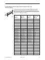
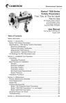
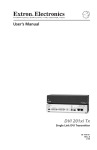
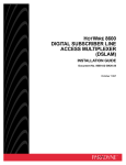
TM
HotWire 8546 Digital Subscriber Line (DSL) Card
Installation Instructions
Document Number 8546-A2-GN10-20
October 1997
What is a 8546 DSL Card?
A Digital Subscriber Line (DSL) 8546 card is a circuit card assembly (CCA) that
contains four Rate Adaptive Digital Subscriber Line (RADSL) ports, an Ethernet
interface to the Internet Service Provider (ISP), and a processor. The processor
controls the RADSL ports and forwards the packet traffic to and from the Ethernet
and DSL interfaces. When the 8546 DSL card is used in a HotWire 8600 or 8800
DSL Access Multiplexer (DSLAM) chassis connected to a HotWire 5446 Remote
Termination Unit (RTU), it provides high-speed Internet or Intranet access with
dynamic IP addressing and enhanced security over traditional twisted-pair
telephone wiring.
! HANDLING PRECAUTIONS FOR
STATIC-SENSITIVE DEVICES
This product is designed to protect sensitive components from damage
due to electrostatic discharge (ESD) during normal operation. When
performing installation procedures, however, take proper static control
precautions to prevent damage to equipment. If you are not sure of the
proper static control precautions, contact your nearest sales or service
representative.
496-15104
Package Checklist
Verify that your package contains the following:
DSL CCA
Warranty card
Tools Required
Small- to medium-size flat-blade screwdriver to install the DSL card.
8546-A2-GN10-20
October 1997
1
Technical Specifications
Specifications
Criteria*
Size
10.4 inches (L) x 11.15 inches (H) x .8 inches (W)
Weight
Approx. 1.4 lbs.
Approvals
Safety Certifications
Refer to the equipment’s label for approvals on product.
Power
The DSL card contains a DC-to-DC converter that
requires – 48V power input. The – 48V power is
distributed through the HotWire DSLAM backplane.
Maximum Power Dissipation = 18 watts
Physical Environment
Operating temperature
32° to 122°F (0° to 50°C)
Storage temperature
– 4° F (–20°C) to 158° F (70°C)
Relative humidity
5% to 85% (noncondensing)
Shock and vibration
Withstands normal shipping and handling.
* Criteria of technical specifications are subject to change without notice.
Planning the DSL Card Installation
Review the following list to help plan for the installation.
Obtain the applicable cables; refer to the next section, Cables You Need.
Make sure the HotWire DSLAM chassis is installed and power is supplied to
the chassis.
After the DSL card is installed, there are configuration instructions that must
be performed before you can begin to use the DSL cards for Internet or
Intranet connectivity. Refer to the HotWire DSLAM for 8540 and 8546 DSL
Cards User’s Guide, Document No. 8000-A2-GB20, for more detailed
configuration procedures.
2
October 1997
8546-A2-GN10-20
Cables You Need
The following customer-provided cables are used with this product:
H
Plug-ended Telco 50-pin cable for connection from the HotWire DSLAM Line
port to the CO POTS splitter shelf, Main Distribution Frame (MDF), or other
demarcation point.
H
One 8-pin modular UTP (Unsheilded Twisted Pair) CAT5 cable for each
connection from a LAN/WAN port associated with a 8546 DSL card in the
HotWire DSLAM chassis to the Ethernet hub or switch.
CAUTION:
Use of any non-twisted pair wiring arrangements, such as jumpers, can
cause reduction in overall DSL reach performance, even over short
distances. Please refer to the Special Notice shipped with the
HotWire 8800/8600 DSLAM.
Refer to Pin Assignments on page 9 for pinouts.
Installing 8546 DSL Cards
Use a small- to medium-size flat-blade or Phillips screwdriver to install the
8546 DSL card.
When using a . . .
Install the DSL card into . . .
HotWire 8600 DSLAM base chassis
Slot 2 or 3 (Slot 1 of the HotWire 8600
DSLAM base chassis must contain a
Management Communications
Controller (MCC) card.)
HotWire 8600 DSLAM expansion chassis
Slot 1, 2, or 3
HotWire 8800 DSLAM chassis
Any one of the first 18 slots (i.e., Slot 1
through 18)
An 8546 DSL card can be installed, removed, and replaced from a HotWire
DSLAM chassis without service disruption (i.e., you can replace a card without
powering down the chassis and disrupting service to the other cards in the
chassis).
NOTE:
When installing the 8546 DSL card, you will need to remove the filler plate
before proceeding.
Do not discard unused filler plates. Each slot in the chassis must contain a
circuit card or a filler plate. Store all unused filler plates in a safe place. You
may need to use the filler plates to cover open slots in the chassis at a later
time.
8546-A2-GN10-20
October 1997
3
" Procedure
To install an 8546 DSL card:
1. Remove the filler plate from the desired slot.
2. Insert the 8546 DSL card into this slot:
— For a HotWire 8600 DSLAM chassis – hold the 8546 DSL card
horizontally with component side facing up and insert it into the left and
right card guides.
3
AC
T5A
250V
A
48VDC CLASS 2 OR
LIMITED PWR SOURCE
ET
ol
C
ALM
RADSL
4
RT
3
2
1
ol
SL
C
LINE
LAN/WAN SLOT
MANAGEMENT
PO
X
R
N
DC PWR
TX
FAN
ER
.
.
D
..
A
1
8000
N
X
R
ER
H
B
4 5 6
1
ET
ET
3
2
H
O
SY
ST
K
Alr
m
Te
st
DC FUSES
AC
INPUT
ET
EM
B A B
TX
K
Alr
m
Te
st
ST
O
EM
2
RTN
SY
48V
A
B
STACK
POSITION
IN
OUT
SERIAL
MCC
3
2
1
97-15374-01
— For a HotWire 8800 DSLAM chassis – hold the 8546 DSL card vertically
with component side facing right and insert it into the top and bottom card
guides.
DSL Card
Slot 1
POWER
A
B
ALARMS
Fan Major Minor
SYSTEM
OK
Alm
Test
ETHERN
ET
TX
RX
SYSTE
M
Coll
OK
Alm
Test
ETHERN
ET
TX
RX
Coll
DSL
PORT
1
2
3
4
MCC
DSL
-48V INPUT
SLOTS 13-18
FR GND
RET (A)
B
RET (B)
A
-48V (B)
SLOTS 1 - 6
2
4
6
8
1
3
5
7
LAN/WAN SLOT
10
14
12
16
18
20
15
17
19
MGT
SERIAL
LINES
-48V (A)
SLOTS 7-12
11
13
9
LAN/WAN SLOT
MGT
10BT
ALARM
97-15328
4
October 1997
8546-A2-GN10-20
3. Slide the 8546 DSL card into the slot until the power and network connectors
seat firmly in the mating connectors on the backplane.
CAUTION:
Do not force the 8546 DSL card into the slot. If it does not seat properly,
remove the card and reinstall it. If it still does not seat properly, call
service.
The 8546 DSL card performs a power-up self-test. All of the LEDs turn ON
and OFF briefly. When the self-test is completed successfully, the SYSTEM
OK LED will turn ON. Make sure the SYSTEM OK indicator on the DSL card
faceplate is ON (winking green).
4. If the LED is not ON, refer to the Troubleshooting chapter of the appropriate
HotWire DSLAM Installation Guide.
5. Secure the DSL card by fastening the screws at each end of the faceplate.
NOTE:
The 8546 DSL cards may be replaced without system disruption (i.e., you
can remove and re-install a card without powering down the HotWire DSLAM
chassis and disrupting service to the other cards). To remove an 8546 DSL
card from the HotWire DSLAM chassis, unfasten the screws on both ends of
the faceplate. Then, simply push the ejector handles outward and slide the
card out.
When swapping the old 8546 DSL card with a new 8546 DSL card, it is
important to note that the 8600 DSLAM retains the Media Access Control
(MAC) address, also referred to as the physical address. This means that the
new DSL card will have the same MAC address as the old one.
8546-A2-GN10-20
October 1997
5
Connecting to a POTS Splitter or an MDF
You can connect the HotWire DSLAM chassis containing the 8546 DSL card to a
POTS splitter shelf, MDF, or other demarcation point.
NOTE:
If you are connecting the HotWire DSLAM to a CO POTS splitter, this
procedure assumes that the CO POTS splitter shelf is already installed. For
information on how to install the CO POTS splitter, refer to the HotWire POTS
Splitter Central Office Installation Instructions, Document No. 5020-A2-GN10.
" Procedure
To connect the HotWire DSLAM chassis containing the 8546 DSL card to a POTS
splitter shelf or MDF:
1. Plug the Telco 50-pin cable into the appropriate LINE port on the front panel
of the chassis:
3
2
A
B
1
FAN
ALM
STACK
POSITION
A
LAN/WAN SLOT
MANAGEMENT
DC PWR
LINE
RADSL
8546
RADSL
8546
4
3
2
D
ol
TX
R
ET
..
.
.
8000
4
3
2
D
PO
SL
1
RT
ET
X
ol
N
R
C
TX
X
C
st
N
4 5 6
MCC
ET
RT
SL
1
PO
st
X
ol
N
R
C
TX
EM
Te
ST
ER
ET
st
EM
Te
O
K
Alrm
ST
ET
H
SY
ER
EM
ST
DC FUSES
T4A, MIN. 48V
48VDC CLASS 2 OR
LIMITED PWR SOURCE
Te
H
SY
B A B
AC
INPUT
ER
RTN
ET
A
O
K
Alrm
AC
T5A
250V
48V
H
SY
O
K
Alrm
— On a HotWire 8600 DSLAM chassis:
3
2
1
B
IN
OUT
SERIAL
MCC
1
2
3
Anchor
Mount
Telco 50-Pin
Connector
97-15480-01
6
October 1997
8546-A2-GN10-20
— On a HotWire 8800 DSLAM chassis:
SLOTS 13-18
SLOTS 7-12
LINES
SLOTS 1-6
Anchor Mount
Shorter
Telco
Captive Screw
Telco 50-Pin
Connector
LINES
SLOTS 1-6
97-15325
2. Replace the longer Telco cable captive screw with a shorter connector
captive screw, which is provided with the HotWire DSLAM chassis.
3. Insert a cable tie (provided with HotWire DSLAM chassis) through the tie
mount to hold the Telco 50-pin connector in place. If more than one Telco
cable is being connected, replace the existing cable tie with a single tie to
span the two or three connectors.
4. Make sure the other end is connected to the appropriate POTS splitter shelf,
MDF, or demarcation point.
Refer to Pin Assignments on page 9 for pinouts.
NOTE:
If you are connecting the Telco 25-pair, 50-pin cable to an MDF without a
POTS splitter in the line, a converter may be necessary for terminating the
other end of the cable on a punchdown block before cross-connecting to an
MDF.
8546-A2-GN10-20
October 1997
7
Connecting the DSL Cards to the Ethernet Hubs or Switches
" Procedure
To connect the 8546 DSL cards to the Ethernet hubs or switches:
1. Plug the end of an 8-pin modular cable into the appropriate LAN/WAN SLOT
port of the chassis. For example, if you want to connect to the LAN/WAN port
of an 8546 DSL card, insert the 8-pin modular cable in LAN/WAN Slot #2.
2. Plug the other end of the cable into your Ethernet hub or switch connector.
Refer to Pin Assignments on page 9 for pin assignments.
B
4 5 6
1
..
.
.
RADSL
8546
RADSL
8546
8000
4
3
ol
C
MCC
D
RT
2
SL
1
PO
ol
C
D
FAN
DC PWR
ALM
A
2
1
LINE
LAN/WAN SLOT
MANAGEMENT
B
STACK
POSITION
IN
OUT
SERIAL
MCC
1
2
3
LAN/WAN SLOT
MANAGEMENT
DC PWR
4
3
2
PO
SL
1
RT
ET
N
ol
X
C
R
ER
H
ET
ET
N
X
R
H
ET
ET
N
X
R
TX
ER
H
3
2
A
3
ET
DC FUSES
T4A, MIN. 48V
48VDC CLASS 2 OR
LIMITED PWR SOURCE
TX
ER
EM
K
Alr
m
Te
st
ST
SY
K
Alr
m
Te
st
EM
B A B
AC
INPUT
A
O
ST
RTN
SY
48V
A
O
AC
T5A
250A
TX
K
Alr
m
Te
st
O
SY
ST
EM
— On a HotWire 8600 DSLAM chassis:
B
IN
OUT
MCC
SERIAL
1
2
3
To Hub Connector
97-15375-01
— On a HotWire 8800 DSLAM chassis:
LAN/WAN SLOT
PORT 1
-48V INPUT
SLOTS 13-18
RET (B)
FR GND
B
-48V (B)
A
RET (A)
SLOTS 1 - 6
2
4
6
8
1
3
5
7
4
6
8
1
3
5
7
LAN/WAN SLOT
10
12
14
16
18
13
15
17
20
11
13
9
LAN/WAN SLOT
16
18
20
15
17
19
MGT
SERIAL
MGT
10BT
ALARM
MGT
SERIAL
LINES
-48V (A)
SLOTS 7-12
LAN/WAN SLOT
10
14
12
2
11
9
LAN/WAN SLOT
19
MGT
10BT
ALARM
97-15385
8
October 1997
8546-A2-GN10-20
Pin Assignments
HotWire 8600 DSLAM LAN/WAN Connector Pinouts
The 8-pin modular interface for the LAN/WAN 10BaseT connection on a HotWire
8600 DSLAM chassis has the following pin assignments:
8546-A2-GN10-20
Pin Number
Use
1
TX Data +
2
TX Data –
3
RX Data +
4
Reserved
5
Reserved
6
RX Data –
7
Reserved
8
Reserved
October 1997
Pin 1
Pin 8
97-15449
9
HotWire 8600 DSLAM Telco 50-pin Connector Pinouts for DSL Loops
and POTS Splitters
1
25
26
50
10
97-15526
The Telco 50-pin receptacle on the front panel provides the two-wire loop
interface from each 8546 DSL port to either the POTS Splitter shelf or, if the
loop is not being shared with POTS, then to the MDF. The following table lists
the pin assignments for each of these interfaces.
NOTE:
When the 8600 chassis is the base chassis, the MCC is installed in Slot 1
and the Tip and Ring wiring for Slot 1 is not active.
Also, pins 13 through 25 and 38 through 50 of all HotWire 8600 chassis
are not used.
CONNECTOR
(8546 DSL Slot, Port #)
CONNECTOR PINS
(Tip, Ring)
Slot 1, Port 1
1, 26
Slot 1, Port 2
2, 27
Slot 1, Port 3
3, 28
Slot 1, Port 4
4, 29
Slot 2, Port 1
5, 30
Slot 2, Port 2
6, 31
Slot 2, Port 3
7, 32
Slot 2, Port 4
8, 33
Slot 3, Port 1
9, 34
Slot 3, Port 2
10, 35
Slot 3, Port 3
11, 36
Slot 3, Port 4
12, 37
October 1997
8546-A2-GN10-20
HotWire 8800 DSLAM Telco 50-pin Connector Pinouts for DSL Loops
and POTS Splitters
50
26
The three Telco 50-pin connectors on the 8800 DSLAM Interface Module
provides the two-wire loop interface from each 8546 DSL port to either the
POTS splitter shelf or, if the loop is not being shared with POTS, then to the
MDF. The following table lists the pin assignments for each of these interfaces.
Note that Pins 25 and 50 are not used.
25
1
8546-A2-GN10-20
97-15323
CONNECTOR #1
Slots 1–6
(DSL Card,
Port #)
CONNECTOR #2
Slots 7–12
(DSL Card,
Port #)
CONNECTOR #3
Slots 13–18
(DSL Card,
Port #)
CONNECTOR
PINS
(Tip, Ring)
Card 1, Port 1
Card 7, Port 1
Card 13, Port 1
1, 26
Card 1, Port 2
Card 7, Port 2
Card 13, Port 2
2, 27
Card 1, Port 3
Card 7, Port 3
Card 13, Port 3
3, 28
Card 1, Port 4
Card 7, Port 4
Card 13, Port 4
4, 29
Card 2, Port 1
Card 8, Port 1
Card 14, Port 1
5, 30
Card 2, Port 2
Card 8, Port 2
Card 14, Port 2
6, 31
Card 2, Port 3
Card 8, Port 3
Card 14, Port 3
7, 32
Card 2, Port 4
Card 8, Port 4
Card 14, Port 4
8, 33
Card 3, Port 1
Card 9, Port 1
Card 15, Port 1
9, 34
Card 3, Port 2
Card 9, Port 2
Card 15, Port 2
10, 35
Card 3, Port 3
Card 9, Port 3
Card 15, Port 3
11, 36
Card 3, Port 4
Card 9, Port 4
Card 15, Port 4
12, 37
Card 4, Port 1
Card 10, Port 1
Card 16, Port 1
13, 38
Card 4, Port 2
Card 10, Port 2
Card 16, Port 2
14, 39
Card 4, Port 3
Card 10, Port 3
Card 16, Port 3
15, 40
Card 4, Port 4
Card 10, Port 4
Card 16, Port 4
16, 41
Card 5, Port 1
Card 11, Port 1
Card 17, Port 1
17, 42
Card 5, Port 2
Card 11, Port 2
Card 17, Port 2
18, 43
Card 5, Port 3
Card 11, Port 3
Card 17, Port 3
19, 44
Card 5, Port 4
Card 11, Port 4
Card 17, Port 4
20, 45
Card 6, Port 1
Card 12, Port 1
Card 18, Port 1
21, 46
Card 6, Port 2
Card 12, Port 2
Card 18, Port 2
22, 47
Card 6, Port 3
Card 12, Port 3
Card 18, Port 3
23, 48
Card 6, Port 4
Card 12, Port 4
Card 18, Port 4
24, 49
October 1997
11
8546 DSL Card LEDs
The following table describes the meaning and states of the LEDs on the 8546
DSL card faceplate.
ST
SY
t
EM OK Alrm Tes
Type
LED
LED is . . .
Indicating . . .
SYSTEM
OK
Green,
Winking*
Normal operation; card functioning normally.
Off
No power to card or card failure.
Amber
Alarm present on 8546 DSL card.
On
No alarms.
Amber
Test in progress.
Off
No tests.
Green
Blinking
A packet is being sent.
Off
Inactive.
Green
Blinking
A packet is being received.
Off
Inactive.
Off
Normal operation.
Blinking
A collision has been detected.
Green
Link is up.
Off
DSL link is down or disabled.
Amber
DSL handshake and PPP startup in progress.
Green
Link is up.
Off
DSL link is down or disabled.
Amber
DSL handshake and PPP startup in progress.
Green
Link is up.
Off
DSL link is down or disabled.
Amber
DSL handshake and PPP startup in progress.
Green
Link is up.
Off
DSL link is down or disabled.
Amber
DSL handshake and PPP startup in progress.
ET
Alrm
H
ER
N
ET
TX
Test
R
X
C
l
ol
ETHERNET
TX
SL
D
RT
PO
1
2
RX
3
4
Coll
DSL PORT
1
2
3
4
RADSL
* Winking describes a recurring pulse when the LED is ON longer than OFF at a ratio of
approximately 10:1.
8546
97-15387
*8546–A2–GN10–20*
12
October 1997
8546-A2-GN10-20