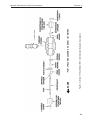
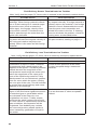
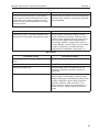
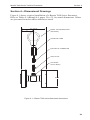
1
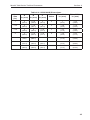
Barton® 7000 Series
Turbine Flowmeters
71xx, 72xx, & 73xx for Liquid
74xx for Gas
CE marked meters conform
to the European Union
Pressurized Equipment
Directive (PED), 97/23/EC
User Manual
Part No. 9A-11350, Rev. 01
August 2009
Table of Contents
Safety Information............................................................................................. 2
Section 1—Introduction..................................................................................... 3
Barton 7000 Series Flowmeters.................................................................... 3
Specifications—7000 Series Turbine Flowmeters......................................... 3
Electrical Classification.............................................................................. 3
Pressure Boundary Certification................................................................ 4
Measurement Performance........................................................................ 4
Specifications—Standard Pickup Coil ....................................................... 5
CE Markings (for PED flowmeters only)........................................................ 5
Section 2—Installation and Operation............................................................... 7
Unpacking...................................................................................................... 7
Unpacking Procedure................................................................................. 7
Best Practices for Installation........................................................................ 9
Filtration..................................................................................................... 9
Electrical Installation.................................................................................. 9
Flowmeter Position..................................................................................... 9
Flowmeter Location.................................................................................. 10
Bolt Size/Torque Requirements................................................................ 12
System Pressure ..................................................................................... 13
Installation Procedure.................................................................................. 13
Section 3—Maintenance................................................................................. 17
Routine Maintenance Checklist................................................................... 17
Parts Replacement...................................................................................... 18
Repair Kits................................................................................................... 18
Disassembly/Assembly................................................................................ 21
Model 7100 Fractional-Sized Flowmeters................................................ 21
Model 7100/7300 Flowmeters (1 in. and larger)...................................... 22
Model 7200/7400 Flowmeters.................................................................. 24
Electrical Pickup Coil Check........................................................................ 25
Troubleshooting........................................................................................... 25
Section 4—Dimensional Drawings.................................................................. 29
Safety Information
Before installing this instrument, become familiar with the installation instructions in Section 2.
!
WARNING: This symbol identifies information about practices or circumstances that can lead to personal injury or death, property damage, or
economic loss.
CAUTION: Indicates actions or procedures which if not performed correctly
may lead to personal injury or incorrect function of the instrument
or connected equipment.
IMPORTANT: Indicates actions or procedures which may affect instrument operation or
may lead to an instrument response that is not planned.
2
Model 7000 Series Turbine Flowmeter
Section 1
Section 1—Introduction
Barton 7000 Series Flowmeters
Barton 7000 Series flowmeters are specially designed to accommodate a
broad range of precise fluid measurement applications. They can accept larger
flow rates with lower pressure drops than other meters in their class, and feature a self-flushing design for longer sustained accuracy. Their high-frequency
digital output is ideal for interfacing with digital readout equipment. The 7000
Series' symmetrical bi-directional design supports reverse flow applications,
without reducing accuracy or flow capacity.
All meters are shipped with a pickup coil. Each meter assembly includes two
locknuts, two flow straightener tube assemblies, a center shaft, two diffusers, and a rotor, and is factory-calibrated with water. Bearing type varies with
models: Models 7100 and 7300 feature wear-resistant tungsten carbide sleeve
bearings and thrust washers. Models 7200 and 7400 feature self-lubricating,
precision stainless steel ball bearings. The Model 7400 features bearings with
dry lubricant impregnated ball separators.
During operation, fluid passes over the diffuser section and is accelerated onto
a multi-blade hydro-dynamically balanced turbine rotor. The rotor speed is
proportional to the volumetric flow rate. As the rotor turns, a reluctance type
pickup coil (mounted on the meter) senses the passage of each blade tip and
generates a sine wave output with a frequency that is directly proportional to
the flow rate.
The rotor is the only moving part of the Barton turbine flowmeter. The small
lightweight rotor hubs ensure fast response to process flow changes. The rotor
is hydro-dynamically balanced during operation, eliminating the need for mechanical thrust leveling. This low-friction design improves metering linearity
and reduces wear and maintenance.
The pickup coil is inserted into a conduit adapter that is welded to the outside
of the turbine body. The boss is explosion-proof/flameproof with 3/4" male
NPT electrical threads. The pickup coil can be removed for troubleshooting
without depressurizing the meter or stopping fluid flow.
Specifications—7000 Series Turbine Flowmeters
Electrical Classification
•
Explosion-proof/Flameproof CSA listed Class I, Division 1, Group
B,C,D; Class II, E,F,G; Class III, Enclosure 4 waterproof to NEC (USA)
and CEC (Canadian) standards, including single seal certification to
ANSI 12.27.0-1.
3
Section 1
•
Model 7000 Series Turbine Flowmeter
Intrinsically Safe/Non-incendive approved to various standards as
governed by the certification of the readout device and the specific entity
parameters of the pickup coils listed with that device.
Pressure Boundary Certification
•
Conformity to PED 97/23/EC
Measurement Performance
Refer to Cameron product literature (technical data sheets) for full descriptions and capabilities.
•
•
•
•
Linearity (Models 7100, 7200, 7300)*
-- ±1.0% for 1/4-in. and 3/8-in. sizes
-- ±0.5% for 1/2-in., 5/8-in., and 3/4-in. sizes
-- ±0.25% for 1-in. and larger sizes
Linearity (Model 7400)*
-- ±1.0% for single K-factor
Custody transfer approved by Measurement Canada
Temperature Range
-- Model 7100, 7300: -160°F to 850°F (-107°C to 454°C)
-- Model 7200, 7400: -425°F to 570°F (-254°C to 299°C)
For temperature and pressure derating information, see Section 2, Table 2.3
and 2.4, page 15, and Table 2-5, page 16.
The temperature range required for any given application is dependent on the
bearing design, electronics/electrical selections and meter housing materials.
Contact Cameron for help in selecting a meter and components that are appropriate for high-temperature or low-temperature applications.
Meter Pickup Coil(s)
A variable reluctance generating pickup coil contains a permanent magnet and
a wire winding. In Model 7100, 7200 and 7400 flowmeters, the rotor blade of
the turbine meter is made of a ferritic stainless steel such as grade 430. The
movement of the rotor blade in proximity to the magnetic field of the coil tip
produces an AC type voltage pulse within the coil winding. In Model 7300,
the ferritic bars imbedded in the rotor shroud interact with the pickup coil.
Because the bars on the shroud outnumber the blades on a standard rotor, the
7300 flowmeter provides more pulses per unit volume (resolution). This feature is valuable when proving large-capacity meters with a small-volume prover.
Shielded wire cable conveys the output of the pickup coil to compatible electronic instruments to indicate flow rate, record, and/or totalize the volumetric flow. Since the coil itself does not require electrical power, the standard
pickup coil incorporates connection pins that mate to a quick connector.
4
Model 7000 Series Turbine Flowmeter
Section 1
The pickup coil can drive a variety of instruments including flow rate indicators, totalizers, preamplifiers or flow computers/RTUs. Preamplifiers are used
to transmit the coil signal over extended distances to remote-mounted instruments.
The meter may be factory-fitted with multiple coils for redundancy, indication
of flow direction or pulse train verification.
The pickup coil type and magnetic strength vary with application requirements. For coil replacement, refer to the part number etched on the coil body.
Specifications—Standard Pickup Coil
Temperature Range������������������������ -450°F to +450°F (-268°C to +232°C) (not including
meter and mating connectors)
DC Resistance������������������������������� 1200 ohms (nominal)
Inductance�������������������������������������� 450 mh (nominal)
Dielectric Strength Rating��������������� 500 VAC rms minimum
Insulation Resistance Rating���������� 100 megaohms @100V
Number of Pins������������������������������� 2
Connector��������������������������������������� MIL-C-5015 (mates with MS31 06-10SL-4S)
Dimensions������������������������������������� See Section 5 - ODD Drawing
Other models may be suitable, depending on the application. See the Spare
Parts List, page 18, for information on alternate models.
CE Markings (for PED flowmeters only)
Barton 7000 flowmeters that are built to conform to the European Union Pressurized Equipment Directive (PED) are marked with the following information:
•
•
•
•
•
•
•
•
•
•
Part number
Serial number
Maximum working pressure
Minimum working pressure
Minimum temperature (°F, °C)
Nominal diameter
Material
Manufacturer's name and address
CE mark*
Notified body identification number
*1-in. flowmeters are not CE-marked. The basis for PED conformance is
Sound Engineering Practice (SEP).
5
Section 1
6
Model 7000 Series Turbine Flowmeter
Model 7000 Series Turbine Flowmeter
Section 2
Section 2—Installation and Operation
Unpacking
All Barton flowmeters are tested and inspected during manufacture. However,
the instrument should be inspected at time of unpacking to detect any damage
that may have occurred during shipment.
Unpacking Procedure
1. For applications requiring special cleaning/precautions, a polyethylene
bag is used to protect the instrument from contamination. This bag
should be removed only in an extremely clean environment.
2. Unpack the meter and verify the accuracy of the information listed on the
packing slip (proper model number, serial number, calibration data, etc.).
3. Remove the threaded protectors or flange covers from the meter housing.
4. For meters up to 3-inch size, place the meter in a horizontal position
and blow (lung pressure should be sufficient) into the inlet port. Place
larger meters in a horizontal position and turn the rotor by hand or with
a wooden dowel. In either instance, the rotor should turn freely with no
evidence of roughness or binding in the rotation.
5. Visually inspect the meter inside and outside (without disassembling the
meter). Report any visible damage to Cameron immediately.
6. Replace the thread protectors and flange covers, then place the meter
back inside the polyethylene bag. Note: Meters may be stored indefinitely
in the polyethylene bag.
CAUTION: Clean all upstream lines before installing the meter. Foreign debris
will damage or collect on the rotor. Do not blow out liquid lines with
compressed air or gas once the meter has been installed. Do not slug liquid meters with fluid. Carefully fill the line after
installing the meter. After startup, keep the meter full of liquid.
Do not expose Model 7400 gas flowmeters to liquids. They will
damage the meter.
If the end connection leaks at the time of installation, remove pressure before attempting to tighten the seal.
Use appropriate bolts and hardware per ANSI B16.5 and, if applicable, per NACE MRO175 / ISO 15156.
Where process temperatures are high, the turbine meter surfaces
may be hazardous to touch. Exercise caution when operating or
servicing.
7
Section 2
!
Model 7000 Series Turbine Flowmeter
WARNING:
The customer is responsible for ensuring chemical compatibility between
the flowmeter and any fluids being metered.
Never exceed the maximum recommended pressure and temperature
limits.
Never exceed the maximum recommended flow rate for the meter.
For installations where the pressure could exceed the rated maximum
safe working pressure of the turbine meter housing or flanges, the piping
system must include protective measures to prevent over pressure, in
accordance with applicable local and national piping code.
The turbine meter is not designed for high static or dynamic loads at the
end connections. The piping system must be designed with adequate
supports to minimize the loads at the turbine meter, in accordance with
applicable local and national piping code.
The turbine meter may be under pressure. Ensure that the piping system
is completely depressurized before removing the meter for maintenance
or inspection.
8
Model 7000 Series Turbine Flowmeter
Section 2
Best Practices for Installation
Before installing a Barton turbine flowmeter, read the following best practices
in their entirety.
Filtration
All meters should be installed with upstream filtration to isolate the meter
from damage from foreign objects in the piping system. See the Barton 7000
Series product data sheet for recommended filtration size. Cameron offers
start-up screens as an optional accessory to prevent damage from foreign
objects.
Avoid the use of Teflon® tape on body threads. Strands can enter the flowstream and collect on the rotor, causing measurement error.
All meters should be isolated from gas or liquid “slugs” which can cause
damage by over-speed and water hammer.
Electrical Installation
Consider the process operating temperature when selecting the type and
location of electric fitting and instrument components. Heat conducted and
radiated from the turbine can damage wiring, connectors, electrical housing
and circuit boards. The meter can be installed so that the pickup coil is in any
plane. Avoid orienting the pickup coil in a 12 o'clock position in applications
with elevated temperatures.
Where possible, minimize the length of signal transmission cables from the
pickup. The signal from the turbine is a low-voltage AC sine wave that can be
as low as 30mV peak-to-peak. Electrical noise on the wires will cause false
counts on the readout instruments. Direct-mounting a totalizer or preamplifier is preferred. If this is not possible, ensure that the signal cable is not near
power cables, other signal cables, or routed where electrical noise may interfere with signal transmission.
Follow common wiring installation practices, using quality cable (twisted
pair, shielded with ground wire).
Flowmeter Position
Barton turbine flowmeters are calibrated in a horizontal position. Therefore,
the best correlation of calibration occurs when the meter is operated in this
plane. However, the meter will operate satisfactorily in any position.
9
Section 2
Model 7000 Series Turbine Flowmeter
Flowmeter Location
See Figure 2.1 for reference. Location of the flowmeter to obtain optimum
accuracy is dependent upon several factors.
•
•
•
•
Relative to the System—When the flow is expected to be intermittent, the
meter should not be mounted at a low point in the piping system since
solids can settle on, or congeal around the rotor. These solids can cause
the rotor to freeze or otherwise be damaged.
Tolerance to Mechanical Vibration—The turbine meter is constructed
to withstand rugged service. However, meter life can be increased by
locating the meter so as to protect it from the direct shock or mechanical
vibration.
Tolerance to Electrical Interference—To obtain the best electrical signal
output from the meter, locate the meter at a distance from sources of electrical interference. A preamplifier is recommended for use on all installations to reduce the effect of undesired noise.
Where practical, install the meter upstream of control valves and pressure regulators. Where necessary, the meter should be at least 100 pipe
diameters from the valves.
Model 7400 flowmeters feature a pressure tap on the body opposite the rotor.
For compliance with international measurement standards, any pressure sensor used for computation of corrected volume should sense pressure from this
tap.
10
Model 7000 Series Turbine Flowmeter
Section 2
Figure 2.1—Flowmeter piping arrangements
11
Section 2
Model 7000 Series Turbine Flowmeter
Bolt Size/Torque Requirements
Bolt sizes vary with meter size and flange rating. See Table 2.4 for bolt specifications recommended in ASME B16.5-2003.
Torque requirement vary with meter size, threads, and fitting/nut material. See
Table 2.2 for recommended torque values.
Table 2.1—Recommended Bolt Sizes
Meter
Size
(in.)
Flange Rating
150 LB
300 LB
600 LB
900 LB
1500 LB
2500 LB
1/2
2-1/4x1/2
2-1/2x1/2
3x1/2
4-1/4x3/4
4-1/4x3/4
—
3/4
2-1/2x1/2
3x5/8
3-1/2x5/8
4-1/2x3/4
4-1/2x3/4
—
5-1/4x7/8
1
2-1/2x1/2
3x5/8
3-1/2x5/8
5x7/8
5x7/8
1-1/4
2-3/4x1/2
3-1/4x5/8
3-3/4x5/8
5x7/8
5x7/8
5-3/4x1
1-1/2
2-3/4x1/2
3-1/2x3/4
4-1/4x3/4
5-1/2x1
5-1/2x1
6-1/2x1-1/8
2
3-1/4x5/8
3-1/2x5/8
4-1/4x5/8
5-3/4x7/8
5-3/4x7/8
6-3/4x1
2-1/2
3-1/2x5/8
4x3/4
4-3/4x3/4
6-1/4x1
6-1/4x1
7-1/2x1-1/8
3
3-1/2x5/8
4-1/4x3/4
5x3/4
5-3/4x7/8
7x1-1/8
8-1/2x1-1/4
4
3-1/2x5/8
4-1/2x3/4
5-3/4x7/8
6-3/4x1-1/8
7-3/4x1-1/4
9-3/4x1-1/2
5
3-3/4x3/4
4-3/4x3/4
6-1/2x1
7-1/2x1-1/4
9-3/4x1-1/2
11-1/2x1-3/4
6
4x3/4
4-3/4x3/4
6-3/4x1
7-1/2x1-1/8
10-1/4x1-3/8
13-1/2x2
8
4-1/4x3/4
5-1/2x7/8
7-1/2x1-1/8
8-3/4x1-3/8
11-1/2x1-5/8
15x2
10
4-1/2x7/8
6-1/4x1
8-1/2x1-1/4
9-1/4x1-3/8
13-1/4x1-7/8
19x2-1/2
12
4-3/4x7/8
6-3/4x1-1/8
8-3/4x1-1/4
10x1-3/8
14-3/4x2
21x2-3/4
Table 2.2—Torque Values
Torque* inch-lbs (N-m)
Dash
No.
O.D.
Tubing
(inches)
Fittings Threads
(Unified Threads
Class 3A may be
used)
Aluminum & Other
Non-Ferrous Alloy
Fittings & Nuts
Steel & Other
Ferrous Alloy
Fittings & Nuts
8
1/2
3/4-16 NF-3
150-200 (17-22.6)
220-300 (24.8-33.9)
10
5/8
7/8-14 NF-3
205-275 (23.2-31)
300-410 (33.9-46.3)
12
3/4
1-1/16-12 N-3
300-400 (33.9-45.2)
450-600 (50.8-67.8)
16
1
1-5/16-12 N-3
450-600 (50.8-67.8)
675-900 (76.3-101.7)
20
1-1/4
1-5/8-12 N-3
540-720 (61-81.3)
825-1100 (93.2-124.3)
24
1-1/2
1-7/8-12 N-3
680-900 (76.8-101.7)
1010-1350 (114-152.3)
Notes: Completely dry nuts should be torqued to the high value given. When nuts are
lubricated, they should be torqued to the lower value given.
* The applicable torque is determined on the basis of the nut and related fitting regardless of the material that the fitting passes through.
12
Model 7000 Series Turbine Flowmeter
Section 2
System Pressure
The maximum and minimum system pressures must be considered when
installing the turbine meter into the system.
•
Minimum Meter Pressure—To obtain proper response, a back pressure
should be applied to the meter. This back pressure should be at least
twice the pressure drop of the meter at maximum flow (all meters). For
liquid meters, the back pressure should be twice the pressure drop of the
meter at maximum flow, plus twice the fluid vapor pressure.
Minimum Pressure at the Meter = (2 x Net Pressure Drop at Maximum
Flow) + (2x Vapor Pressure of Fluid)
Some piping arrangements cause this amount of back pressure on the meter due to downstream restriction, valves, etc. If additional back pressure
is needed, a downstream orifice or valve can be added in accordance with
the piping arrangements shown in Figure 2.1, page 11.
Installation Procedure
Prior to installing the turbine meter into the system, perform the following:
1. Install a “spool piece” and allow sufficient flow through the system to
completely flush any foreign material from the system. If foreign material is expected in the flow the fluid should be filtered. This is especially
important for ball bearing meters.
2. Remove gas "slugs" from liquid meter flow lines and liquid "slugs" from
gas meter flow lines.
3. If the meter is used in a cryogenic application, (available by special order
only; limited to model 7200 meters), install a bypass for cooling the piping without passing fluid through the meter (Figure 2.2). This prevents
gasification of the cryogenic fluid and ensures all flow passing through
the meter is liquid.
Figure 2.2—Flowmeter bypass
4. If liquid meters are to be "proved" for accuracy in-situ using a portable
prover, install prover taps per API standards.
5. Install a straight section of pipe on either side of the meter. This pipe
must be the same nominal pipe size as the meter with a length of at least
10 pipe diameters upstream and 5 pipe diameters downstream. (For
example, a flowmeter with a 2-in. nominal diameter requires a 2-in. pipe.
13
Section 2
6.
7.
8.
9.
Model 7000 Series Turbine Flowmeter
The section of straight pipe upstream must be 20 in.; the section downstream must be 10 in.) Do not install throttling valves within 100 pipe
diameters upstream of the flowmeter.
Install a flow straightener upstream and downstream of the meter. The
applicable filter should be selected according to ISA Standard RP31.1.
All fluids to be used with a Model 7200 turbine meter should be free of
particles larger than approximately 10 microns.
Align the meter bore with the pipe, ensuring that the direction of flow
corresponds with the direction of the arrow engraved on the meter body.
All Barton turbine flowmeters have “IN” and “OUT” stamped into the
housings to identify the direction of flow in which the meter was calibrated.
Insert bolts and apply torque for a leak-proof seal. See Tables 2.1 and 2.2,
page 11, for bolt size and torque requirements.
Install the magnetic pickup as follows.
a. Screw the magnetic pickup clockwise into the conduit adapter until
finger-tight. Then rotate the pickup counter-clockwise one quarter
turn. Do not tighten with pliers.
b. Turn the jam nut clockwise until the pickup is secure. A ¾-in.
12-point deep thin wall socket wrench (Part No. 9A-100013146) is
required.
c. Attach the signal cable connector to the pickup and turn the swivel
nut until the connection is snug. Do not over-tighten.
CAUTION:
The meter pressure rating has been determined using standard
methods and stress allowable values without specific consideration
for corrosion (neither internal nor external) or fatigue. The piping
system designer should appropriately derate any meter where these
considerations are significant issues.
IMPORTANT: Any marked maximum working pressure (MWP) rating refers to the
meter room temperature pressure rating. For operation at other temperatures, see the pressure derating information in Tables 2.3 and 2.4, page
15, and Table 2.5, page 16.
14
Model 7000 Series Turbine Flowmeter
Section 2
Table 2.3—Pressure Ratings (PSI)
Flange
Class
Type 316 SST 7000 Series Turbine Meters with ASME B16.5 Flanges
-20°F
(-29°C)
100°F
(38°C)
200°F
(93°C)
300°F
(149°C)
400°F
(204°C)
500°F
(260°C)
600°F
(316°C)
650°F
(343°C)
700°F
(371°C)
750°F
(399°C)
CL 150
275
275
235
215
195
170
140
125
110
95
CL 300
720
720
620
560
515
480
450
440
435
425
CL 400
960
960
825
745
685
635
600
590
580
570
CL 600
1440
1440
1240
1120
1025
955
900
885
870
855
CL 900
2160
2160
1860
1680
1540
1435
1355
1325
1305
1280
CL 1500
3600
3600
3095
2795
2570
2390
2255
2210
2170
2135
CL 2500
6000
6000
5160
4660
4280
3980
3760
3680
3620
3560
Size
Type 316 SST 7000 Series Turbine Meters with NPT/BSP Threads
-20°F
(-29°C)
100°F
(38°C)
200°F
(93°C)
300°F
(149°C)
400°F
(204°C)
500°F
(260°C)
600°F
(316°C)
650°F
(343°C)
700°F
(371°C)
750°F
(399°C)
1" *
4400
4400
3791
3417
3136
2926
2762
2715
2645
2621
1-1/4"
4000
4000
3447
3106
2851
2660
2511
2468
2404
2383
1-1/2"
3200
3200
2757
2485
2281
2128
2009
1974
1923
1906
2"
2650
2650
2284
2058
1889
1762
1663
1635
1593
1579
* 1-in. flowmeters are not CE marked. The basis for PED conformance is Sound Engineering Practice (SEP).
Table 2.4—Pressure Ratings (MPa)
Flange
Class
Type 316 SST 7000 Series Turbine Meters with ASME B16.5 Flanges
-29°C
38°C
50°C
100°C
150°C
200°C
250°C
300°C
325°C
350°C
CL 150
1.9
1.9
1.8
1.6
1.5
1.4
1.2
1.0
0.93
0.84
CL 300
5.0
5.0
4.8
4.3
3.9
3.6
3.3
3.2
3.1
3.0
CL 400
6.6
6.6
6.4
5.6
5.1
4.8
4.5
4.2
4.1
4.0
CL 600
9.9
9.9
9.6
8.4
7.7
7.1
6.7
6.3
6.2
6.1
CL 900
15.0
15.0
14.0
13.0
12.0
11.0
10.0
9.5
9.3
9.1
CL 1500
25.0
25.0
24.0
21.0
19.0
18.0
17.0
16.0
15.0
15.0
CL 2500
Size
41.4
41.4
40.1
35.2
32.1
29.7
27.8
26.4
25.7
25.3
Type 316 SST 7000 Series Turbine Meters with NPT/BSP Threads
-29°C
38°C
93°C
149°C
204°C
260°C
316°C
343°C
371°C
399°C
1" *
30.3
30.3
26.1
23.6
21.6
20.2
19.0
18.7
18.2
18.1
1-1/4"
27.6
27.6
23.8
21.4
19.7
18.3
17.3
17.0
16.6
16.4
1-1/2"
22.1
22.1
19.0
17.1
15.7
14.7
13.9
13.6
13.3
13.1
2"
18.3
18.3
15.8
14.2
13.0
12.2
11.5
11.3
11.0
10.9
* 1-in. flowmeters are not CE marked. The basis for PED conformance is Sound Engineering Practice (SEP).
15
Section 2
Model 7000 Series Turbine Flowmeter
Table 2.5—Pressure Ratings (Bar)
Flange
Class
Type 316 SST 7000 Series Turbine Meters with ASME B16.5 Flanges
-29°C
38°C
50°C
100°C
150°C
200°C
250°C
300°C
325°C
CL 150
19.0
19.0
18.4
16.2
14.8
13.7
12.1
10.2
9.3
8.4
CL 300
49.6
49.6
48.1
42.8
38.5
35.7
33.4
31.6
30.9
30.3
CL 400
66.2
66.2
64.2
56.3
51.3
47.6
44.5
42.2
41.2
40.4
CL 600
99.3
99.3
96.2
84.4
77.0
71.3
66.8
63.2
61.8
60.7
CL 900
148.9
148.9
144.3
126.6
115.5
107.0
100.1
94.9
92.7
91.0
CL 1500
248.2
248.2
240.6
211.0
192.5
178.3
166.9
158.1
154.4
151.6
CL 2500
413.7
413.7
400.9
351.6
320.8
297.2
278.1
263.5
257.4
252.7
Size
350°C
Type 316 SST 7000 Series Turbine Meters with NPT/BSP Threads
-29°C
38°C
93°C
149°C
204°C
260°C
316°C
343°C
371°C
399°C
1" *
303.4
303.4
261.4
235.6
216.2
201.7
190.4
187.2
182.4
180.7
1-1/4"
275.8
275.8
237.7
214.1
196.6
183.4
173.1
170.2
165.7
164.3
1-1/2"
220.6
220.6
190.1
171.3
157.3
146.7
138.5
136.1
132.6
131.4
2"
182.7
182.7
157.5
141.9
130.2
121.5
114.7
112.7
109.8
108.9
* 1-in. flowmeters are not CE marked. The basis for PED conformance is Sound Engineering Practice (SEP).
16
Model 7000 Series Turbine Flowmeter
Section 3
Section 3—Maintenance
Barton 7000 Series flowmeters have a proven history of providing long cycle
periods between maintenance intervals. It is recommended the meters be
inspected every 3 to 5 years unless measurement anomalies occur. Many
installations are suitable for much longer maintenance cycles.
Routine Maintenance Checklist
Perform the following steps as part of your routine maintenance.
1. Before removing internal components from the meter, check the rotor to
determine if it turns freely.
2. Disassemble the meter and check for evidence of erosion or other mechanical damage to the interior of the meter body or internal components.
a. The rotor blade edges should be defined and not excessively rounded.
b. The rotor should be uniform and symmetrical.
c. Models 7100 and 7300 tungsten carbide bushings and bearings
should be free of radial play.
d. Model 7400 tungsten carbide bushings and bearings are dry lubricated and may emit a uniform sound and may not feel perfectly smooth
when rotated. This is normal.
e. Model 7400 and Model 7200 bearings should be free of axial and
radial play.
3. In a vented area, clean each part thoroughly in di-chlorethylene or any
similar cleaning solvent before reassembling the meter.
17
Section 3
Model 7000 Series Turbine Flowmeter
Parts Replacement
See Table 3.1 for a list of recommended spare parts.
!
WARNING: Use only spare parts identified in this manual. Cameron bears
no legal responsibility for the performance of a product that has been
serviced or repaired with parts that are not authorized by Cameron.
Table 3.1—Electrical Spare Parts
Pickup Coils
Meter Size
1/4-in. through 3/4-in.
1-in. through 12-in.
Temperature Rating
Part Number
-450°F to +450°F
(-268°C to +232°C)
9A-2112-0001A-01
-58°F to +347°F
(-50°C to +175°C)
9A-2113-0001A-01*
-450°F to 850°F
(-268°C to +454°C)
9A-2114-0001A-01**
-450°F to +450°F
(-268°C to +232°C)
9A-2112-0001A-02
-58°F to +347°F
(-50°C to +175°C)
9A-2113-0001A-02*
-450°F to 850°F
(-268°C to +454°C)
9A-2114-0001A-02**
Connectors and Cables - Partial Listing
Connector Only (MS 3106-10SL-4S or
equivalent - rubber boot included)
9A-8001-1009B
Connector w/12" wires
9A-0818-1020B
Connector w/12" wires (required in some
intrinsicallly safe installations)
9A-0818-1050B
Adapter/Reducer, 1" MNPT x 3/4" FNPT
9A-0159-1008T
* Suitable for Intrinsically Safe/ATEX approved meters
** Suitable only for flowmeters that have been approved by Cameron for use at
extreme temperatures. Contact Cameron for details.
Repair Kits
Should an internal component of a Barton turbine flowmeter require replacement, replace all internals with a repair kit. See Tables 3.2 through 3.4, page
19, and Table 3.5, page 20, for a complete list of repair kits.
Repair kits are factory-calibrated with water using eight data points and two
repeat points. They are calibrated with the meter in which they are to be installed. Therefore, they should be purchased with the meter to prevent downtime. If the repair kit has not been calibrated and on-site proving (calibration)
cannot be performed, return the meter and the repair kit to the factory for
calibration.
18
Model 7000 Series Turbine Flowmeter
Section 3
Table 3.2—Model 7100 Kits
Model
Meter Size
Part Number
7184
1/2"
9A-7084-9001-BA-01
7185
5/8"
9A-7085-9001-BA-01
7186
3/4"
9A-7086-9001-BA-01
7101
1"
9A-7001-9001-BA-01
7145
1-1/4"
9A-7045-9001-BA-01
7146
1-1/2"
9A-7046-9001-BA-01
7102
2"
9A-7002-9001-BA-01
7103
3"
9A-7003-9001-BA-01
7104
4"
9A-7004-9001-BA-01
7106
6"
9A-7006-9001-BA-01
7108
8"
9A-7008-9001-BA-01
7110
10"
9A-7010-9001-BA-01
7112
12"
9A-7012-9001-BA-01
Table 3.3—Model 7200 Kits
Model
Meter Size
Part Number
7282
1/4"
9A-7082-9001-BA-02
7283
3/8"
9A-7083-9001-BA-02
7284
1/2"
9A-7084-9001-BA-02
7285
5/8"
9A-7085-9001-BA-02
7286
3/4"
9A-7086-9001-BA-02
7201
1"
9A-7001-9001-BA-02
7245
1-1/4"
9A-7045-9001-BA-02
7246
1-1/2"
9A-7046-9001-BA-02
7202
2"
9A-7002-9001-BA-02
7203
3"
9A-7003-9001-BA-02
7204
4"
9A-7004-9001-BA-02
7206
6"
9A-7006-9001-BA-02
Table 3.4—Model 7300 Kits
Model
Meter Size
Part Number
7102
2"
9A-7002-9001-BA-01
7103
3"
9A-7003-9001-BA-01
7304
4"
9A-7004-9001-BA-03
7306
6"
9A-7006-9001-BA-03
7308
8"
9A-7008-9001-BA-03
7310
10"
9A-7010-9001-BA-03
7312
12"
9A-7012-9001-BA-03
19
Section 3
Model 7000 Series Turbine Flowmeter
Table 3.5—Model 7400 Kits
20
Model
Meter Size
Part Number
7486
3/4"
9A-7086-9001-BA-04
9A-7050-9001-BA-04
7450
1"
7475
1"
9A-7075-9001-BA-04
7401
1"
9A-7001-9001-BA-04
7445
1-1/4"
9A-7045-9001-BA-04
7446
1-1/2"
9A-7046-9001-BA-04
7402
2"
9A-7002-9001-BA-04
7403
3"
9A-7003-9001-BA-04
7404
4"
9A-7004-9001-BA-04
7406
6"
9A-7006-9001-BA-04
7408
8"
9A-7008-9001-BA-04
7410
10"
9A-7010-9001-BA-04
7412
12"
9A-7012-9001-BA-04
Model 7000 Series Turbine Flowmeter
Section 3
Disassembly/Assembly
!
WARNING: Before disassembling or assembling a Barton turbine flowmeter, read all safety cautions and warnings on pages 7 and 8.
A special tool can be fabricated for disassembling Barton 7000 Series flowmeters. See Figure 3.1 for a fabrication diagram.
Figure 3.1—Flowmeter disassembly tool
Model 7100 Fractional-Sized Flowmeters
IMPORTANT: Field repairs for 1/4 in. and 3/8 in. Model 7100 flowmeters are not recommended. These meters must be returned to the factory for disassembly
and repair.
FLOW
* PART OF BUSHING ASSEMBLY
Figure 3.2—Model 7100 fractional-sized flowmeters
21
Section 3
Model 7000 Series Turbine Flowmeter
Model 7100/7300 Flowmeters (1 in. and larger)
1. Remove downstream locknut (see Figure 3.3, page 23).
2. Insert hook end of special disassembly tool into downstream flow
straightener tube and engage hook on inside edge of tube.
3. Slide impact hammer along tube, striking the anvil. Use light force and
repeat until tube is ejected from meter housing.
4. Remove downstream diffuser, wear washers, journal bearing, rotor
bushing, and rotor. The bushing is press-fitted into the rotor and both are
removed simultaneously from the housing.
5. From the upstream end of the housing, remove the center shaft, wear
washer, upstream diffuser, upstream flow straightener, tube assembly, and
upstream locknut as a unit. Disassemble as required.
To reassemble the meter, perform the following steps:
1. Assemble the center shaft, wear washer, upstream diffuser, upstream flow
straightener, tube assembly, and upstream locknut.
2. Assemble the downstream diffuser, wear washers, journal bearing, and
rotor bushing/rotor.
IMPORTANT: All rotors are marked (with a line or dot) on the upstream end of the rotor.
To maintain calibration, ensure the marked end of the meter is installed
on the upstream end of the meter.
3. Insert the downstream flow straightener tube assembly into the meter
housing and position on the center shaft. Align the two straightener assemblies as close as possible to maintain calibrated configuration.
4. Attach and tighten the downstream locknut.
22
* PART OF BUSHING ASSEMBLY ON MODEL 7300 METERS
Figure 3.3—Model 7100 and Model 7300 meter disassembly/assembly sequence
FLOW
*
Model 7000 Series Turbine Flowmeter
Section 3
23
Section 3
Model 7000 Series Turbine Flowmeter
Model 7200/7400 Flowmeters
1. Remove the downstream locknut (see Figure 3.4).
2. Insert the hook end of the special disassembly tool into the downstream
flow straightener tube and engage the hook on the inside edge of tube.
3. Slide the impact hammer along tube, striking the anvil. Use light force
and repeat until the tube is ejected from the meter housing.
4. Remove the downstream diffuser, spacer, ball bearings, adapter, and rotor.
5. From the upstream end of the housing, remove the center shaft, wear
washer, upstream diffuser, upstream flow straightener, tube assembly, and
upstream locknut as a unit. Disassemble as required.
To assemble the meter, perform the following steps.
1. Assemble the center shaft, wear washer, upstream diffuser, upstream flow
straightener, tube assembly, and upstream locknut.
2. Assemble the downstream diffuser, wear washers, journal bearing, and
rotor bushing/rotor.
IMPORTANT: All rotors are marked (with a line or dot) on the upstream end of the rotor.
To maintain calibration, ensure the marked end of the meter is installed
on the upstream end of the meter.
3. Insert the downstream flow straightener tube assembly into the meter
housing and position on the center shaft. Align the two straightener assemblies as close as possible to maintain calibrated configuration.
4. Attach and tighten the downstream locknut.
FLOW
* PART OF SHAFT ON MODEL 7200 METERS 3/4 IN. AND SMALLER
Figure 3.4—Model 7200 and Model 7400 flowmeter disassembly/assembly sequence
24
Model 7000 Series Turbine Flowmeter
Section 3
Electrical Pickup Coil Check
Items Needed: Ohmmeter and Oscilloscope
1. With an ohmmeter, measure the resistance between the pickup pins. The
resistance should be approximately 1200 ohms.
2. Measure the resistance between each pin and the pickup coil housing.
The resistance should be at least 100 megohms.
3. If either of the above readings are not as specified, replace the pickup
coil.
4. Connect an oscilloscope to the pickup coil. Check the signal-to-noise
ratio by comparing the peak-to-peak voltage while running the meter at
the minimum flow rate versus the peak-to-peak voltage at no flow. The
ratio shall be in the area of 20:1 or higher.
If the signal-to-noise ratio is not as required, examine the immediate area
for either radiated or conducted type of electrical interference. Minimize
the electrical interference by removing the source of the interference or
by reorienting the meter.
The most effective method of locating the source of electrical interference is to turn off the power to electrical machinery or electronic devices
one item at a time, and observe the change in amplitude of the interference signal.
IMPORTANT: A low signal-to-noise ratio can feed deceptive information to the electronic instrumentation of the system. The addition of a preamplifier at the
turbine meter will provide improved signal-to-noise ratio.
Troubleshooting
Turbine meter system malfunctions are usually restricted to two areas: electrical/electronic, or mechanical.
When a malfunction or an apparent malfunction occurs, the electrical/electronic systems should first be thoroughly checked in accordance with the
manufacturer's recommended procedures, prior to checking the turbine meter.
Only when the source of the malfunction cannot be found in the electrical or
electronic systems should the turbine meter be inspected.
IMPORTANT: Before performing any troubleshooting, refer to information, instructions,
and Warning/Caution notices in Sections 2 and 3.
25
Section 3
Model 7000 Series Turbine Flowmeter
Fluid Delivery Greater Than Indicated on Totalizer
Note: Verify that the proper "K" factor value is entered in the electronic readout device.
Possible Cause
Corrective Action
Foreign material collected on rotor or
bearings. When foreign material collects
on or in the bearings or if material wraps
around the rotor (such as strands of
teflon tape), the angular velocity of the
rotor will be reduced. This allows more
fluid to pass through the meter than the
pulse train indicates.
Remove the meter from the line and visually inspect internally. If foreign material is
present, remove the material. If no foreign
material is found, disassemble the meter,
clean the parts, and reassemble and
reinstall the meter in the line. If cleaning
does not eliminate the problem, check for
bearing wear, as described below.
Excessive bearing wear. Excessive bearing wear will lower the angular velocity of
the rotor and rotation may stop completely. Effect is the same as with foreign
material.
Replace meter internals with a repair kit.
See part numbers, starting on page 19.
Fluid Delivery Less Than Indicated on Totalizer
Note: Verify that the proper "K" factor value is entered in electronic readout device.
Possible Cause
Corrective Action
Ground loop in electrical circuit.
See manufacturer's manual.
Gasification of liquid in meter. Cameron
recommends that a back pressure be
applied to the system. This back pressure
should be twice the magnitude of the
net pressure loss through the meter plus
twice the magnitude of the vapor pressure of the liquid being metered. If this
back pressure is not maintained, gasification can occur within the meter, causing
an over-spin of the rotor. This will indicate
a greater than actual delivery and cause
damage to the bearings.
Provide a back pressure at the meter
by using accepted design means and
practices.
Entrained gas or bubbles in metered
liquid. If the fluid has a significant amount
of entrained gas or gas bubbles which
are released in the reservoir, over
registration can occur. Turbine meters
measure the actual volume of the liquid.
If a unit volume is expanded by entrained
gas or bubbles, this expansion will be
registered. Gas bubbles may cavitate
the rotor and produce effects similar to
those caused by gasification of liquid in
the meter.
Eliminate entrained gas or bubbles by use
of an air eliminator or other acceptable
method.
26
Model 7000 Series Turbine Flowmeter
Section 3
Possible Cause
Corrective Action
Excessive electrical noise. Unsheilded
cable used in close proximity to an electrical motor can cause electrical noise,
which can be misinterpreted by the totalizer as volume.
Ensure that the cable used to connect the
pickup to the totalizer is properly shielded
and grounded.
Erratic Output
Possible Cause
Corrective Action
Sensitivity, noise, or foreign material disturbing the fluid profile through the meter.
Verify proper sensitivity setting of electronic readout instrument; remove intermittent noise signals; remove meter from
the line and inspect flow straighteners
for foreign material; inspect the rotor for
broken blades; check meter run for proper
length of upstream and downstream
straight pipe installation (see page 11).
No Output
Possible Cause
Corrective Action
Wrong or poor electrical cable connections.
Check connections, correct as necessary.
No flow.
Verify flow through pipe.
Defective pickup coil.
Remove and check the pickup coil for
continuity between the pins, replace if
defective.
Frozen rotor.
Remove meter from line and check rotor
for free-spin. If necessary, replace rotor.
Inspect bearings and bearing surfaces for
foreign material. Inspect wear washers,
spacers, diffuser, and rotor hub. If no
wear is found, clean and reassemble. If
wear is found, replace parts and recalibrate.
27
Section 3
28
Model 7000 Series Turbine Flowmeter
Model 7000 Series Turbine Flowmeter
Section 4
Section 4—Dimensional Drawings
Figure 4.1 shows a typical installation of a Barton 7000 Series flowmeter.
Refer to Tables 4.1 through 4.6, pages 30 to 35, for actual dimensions. Values
are presented in inches unless otherwise stated.
A ± 1/16 in.
C
MODEL 818 PREAMPLIFIER
(OPTIONAL)
STAND-OFF TUBE
ELECTRICAL CONNECTOR
PICKUP COIL
COIL BOSS
(3/4 IN. MNPT)
B DIA.
Figure 4.1—Barton 7000 series flowmeter dimensions
29
Section 4
Model 7000 Series Turbine Flowmeter
Table 4.1—150# ANSI Dimensions
Line
Size
(in.)
30
No. of
Holes
Dia. of Holes
in. (mm)
Dia. of B.C.
in. (mm)
2-1/2
(63.5)
4
5/8
(15.9)
2-3/8
(60.3)
3-1/2
(88.9)
2-1/2
(63.5)
4
5/8
(15.9)
2-3/8
(60.3)
5
(127)
3-1/2
(88.9)
2-1/2
(63.5)
4
5/8
(15.9)
2-3/8
(60.3)
5/8
5-1/2
(139.7)
3-7/8
(98.4)
2-3/4
(69.9)
4
5/8
(15.9)
2-3/4
(69.9)
3/4
5-1/2
(139.7)
3-7/8
(98.4)
2-3/4
(69.9)
4
5/8
(15.9)
2-3/4
(69.9)
1
5-1/2
(139.7)
4-1/4
(108)
2-3/4
(69.9)
4
5/8
(15.9)
3-1/8
(79.4)
1-1/4
6
(152.4)
4-5/8
(117.5)
3
(76.2)
4
5/8
(15.9)
3-1/2
(88.9)
1-1/2
6
(152.4)
5
(127)
3
(76.2)
4
5/8
(15.9)
3-7/8
(98.4)
2
6-1/2
(165.1)
6
(152.4)
3-1/4
(82.6)
4
3/4
(19.1)
4-3/4
(120.7)
2-1/2
7
(177.8)
7
(177.8)
3-1/2
(88.9)
4
3/4
(19.1)
5-1/2
(139.7)
3
10
(254)
7-1/2
(190.5)
5
(127)
4
3/4
(19.1)
6
(152.4)
4
12
(304.8)
9
(228.6)
6
(152.4)
8
3/4
(19.1)
7-1/2
(190.5)
5
14
(355.6)
10
(254)
7
(177.8)
8
7/8
(22.2)
8-1/2
(215.9)
6
14
(355.6)
11
(279.4)
7
(177.8)
8
7/8
(22.2)
9-1/2
(241.3)
8
16
(406.4)
13-1/2
(342.9)
8
(203.2)
8
7/8
(22.2)
11-3/4
(298.5)
10
20
(508)
16
(406.4)
10
(254)
12
1
(25.4)
14-1/4
(362.0)
12
24
(609.6)
19
(482.6)
12
(304.8)
12
1
(25.4)
17
(431.8)
A
in. (mm)
B
in. (mm)
C
in. (mm)
1/4
5
(127)
3-1/2
(88.9)
3/8
5
(127)
1/2
Model 7000 Series Turbine Flowmeter
Section 4
Table 4.2—300# ANSI Dimensions
Line
Size
(in.)
No.
Holes
Dia. of Holes
in. (mm)
Dia. of B.C.
in. (mm)
2-1/2
(63.5)
4
5/8
(15.9)
2-5/8
(66.7)
3-3/4
(95.3)
2-1/2
(63.5)
4
5/8
(15.9)
2-5/8
(66.7)
5
(127)
3-3/4
(95.3)
2-1/2
(63.5)
4
5/8
(15.9)
2-5/8
(66.7)
5/8
5-1/2
(139.7)
4-5/8
(117.5)
2-3/4
(69.9)
4
5/8
(15.9)
3-1/4
(82.6)
3/4
5-1/2
(139.7)
4-5/8
(117.5)
2-3/4
(69.9)
4
5/8
(15.9)
3-1/4
(82.6)
1
5-1/2
(139.7)
4-7/8
(123.8)
2-3/4
(69.9)
4
3/4
(19.1)
3-1/2
(88.9)
1-1/4
6
(152.4)
5-1/4
(133.4)
3
(76.2)
4
3/4
(19.1)
3-7/8
(98.4)
1-1/2
6
(152.4)
6-1/8
(155.6)
3
(76.2)
4
7/8
(22.2)
4-1/2
(114.3)
2
6-1/2
(165.1)
6-1/2
165.1)
3-1/4
(82.6)
8
3/4
(19.1)
5
(127)
2-1/2
7
(177.8)
7-1/2
(190.5)
3-1/2
(88.9)
8
7/8
(22.2)
5-7/8
(149.2)
3
10
(254)
8-1/4
(209.6)
5
(127)
8
7/8
(22.2)
6-5/8
(168.3)
4
12
(304.8)
10
(254)
6
(152.4)
8
7/8
(22.2)
7-7/8
(200.0)
5
14
(355.6)
11
(279.4)
7
(177.8)
8
7/8
(22.2)
9-1/4
(235.0)
6
14
(355.6)
12-1/2
(317.5)
7
(177.8)
12
7/8
(22.2)
10-5/8
(269.9)
8
16
(406.4)
15
(381)
8
(203.2)
12
1
(25.4)
13
(330.2)
10
20
(508)
17-1/2
(444.5)
10
(254)
16
1-1/8
(28.6)
15-1/4
(387.4)
12
24
(609.6)
20-1/2
(520.7)
12
(304.8)
16
1-1/4
(31.8)
17-3/4
(450.8)
A
in. (mm)
B
in. (mm)
C
in. (mm)
1/4
5
(127)
3-3/4
(95.3)
3/8
5
(127)
1/2
31
Section 4
Model 7000 Series Turbine Flowmeter
Table 4.3—600# ANSI Dimensions
Line
Size
(in.)
32
No.
Holes
Dia. of Holes
in. (mm)
Dia. of B.C.
in. (mm)
2-1/2
(63.5)
4
5/8
(15.9)
2-5/8
(66.7)
3-3/4
(95.3)
2-1/2
(63.5)
4
5/8
(15.9)
2-5/8
(66.7)
5
(127)
3-3/4
(95.3)
2-1/2
(63.5)
4
5/8
(15.9)
2-5/8
(66.7)
5/8
5-1/2
(139.7)
4-5/8
(117.5)
2-3/4
(69.9)
4
3/4
(19.1)
3-1/4
(82.6)
3/4
5-1/2
(139.7)
4-5/8
(117.5)
2-3/4
(69.9)
4
3/4
(19.1)
3-1/4
(82.6)
1
5-1/2
(139.7)
4-7/8
(123.8)
2-3/4
(69.9)
4
3/4
(19.1)
3-1/2
(88.9)
1-1/4
6
(152.4)
5-1/4
(133.4)
3
(76.2)
4
3/4
(19.1)
3-7/8
(98.4)
1-1/2
6
(152.4)
6-1/8
(155.6)
3
(76.2)
4
7/8
(22.2)
4-1/2
(114.3)
2
6-1/2
(165.1)
6-1/2
(165.1)
3-1/4
(82.6)
8
3/4
(19.1)
5
(127.0)
2-1/2
7
(177.8)
7-1/2
(190.5)
3-1/2
(88.9)
8
7/8
(22.2)
5-7/8
(149.2)
3
10
(254)
8-1/4
(209.6)
5
(127)
8
7/8
(22.2)
6-5/8
(168.3)
4
12
(304.8)
10-3/4
(273.1)
6
(152.4)
8
1
(25.4)
8-1/2
(215.9)
5
14
(355.6)
13
(330.2)
7
(177.8)
8
1-1/8
(28.6)
10-1/2
(266.7)
6
14
(355.6)
14
(355.6)
7
(177.8)
12
1-1/8
(28.6)
11-1/2
(292.1)
8
16
(406.4)
16-1/2
(419.1)
8
(203.2)
12
1-1/4
(31.8)
13-3/4
(349.2)
10
20
(508)
20
(508)
10
(254)
16
1-3/8
(34.9)
17
431.8)
12
24
(609.6)
22
(558.8)
12
(304.8)
20
1-3/8
(34.9)
19-1/4
(489.0)
A
in. (mm)
B
in. (mm)
C
in. (mm)
1/4
5
(127)
3-3/4
(95.3)
3/8
5
(127)
1/2
Model 7000 Series Turbine Flowmeter
Section 4
Table 4.4—900# ANSI Dimensions
Line
Size
(in.)
No.
Holes
Dia. of Holes
in. (mm)
Dia. of B.C.
in. (mm)
3-1/2
(88.9)
4
7/8
(22.2)
3-1/4
(82.6)
4-3/4
(120.7)
3-1/2
(88.9)
4
7/8
(22.2)
3-1/4
(82.6)
7
(177.8)
4-3/4
(120.7)
3-1/2
(88.9)
4
7/8
(22.2)
3-1/4
(82.6)
5/8
7
(177.8)
5-1/8
(130.2)
3-1/2
(88.9)
4
7/8
(22.2)
3-1/2
(88.9)
3/4
7
(177.8)
5-1/8
(130.2)
3-1/2
(88.9)
4
7/8
(22.2)
3-1/2
(88.9)
1
8
(203.2)
5-7/8
(149.2)
4
(101.6)
4
1
(25.4)
4
(101.6)
1-1/4
8
(203.2)
6-1/4
(158.8)
4
(101.6)
4
1
(25.4)
4-3/8
(111.1)
1-1/2
9
(228.6)
7
(177.8)
4-1/2
(114.3)
4
1-1/8
(28.6)
4-7/8
(123.8)
2
9
(228.6)
8-1/2
(215.9)
4-1/2
(114.3)
8
1
(25.4)
6-1/2
(165.1)
2-1/2
10
(254)
9-5/8
(244.5)
5
(127)
8
1-1/8
(28.6)
7-1/2
(190.5)
3
10
(254)
9-1/2
(241.3)
5
(127)
8
1
(25.4)
7-1/2
(190.5)
4
12
(304.8)
11-1/2
(292.1)
6
(152.4)
8
1-1/4
(31.8)
9-1/4
(235.0)
5
14
(355.6)
13-3/4
(349.3)
7
(177.8)
8
1-3/8
(34.9)
11
(279.4)
6
14
(355.6)
15
(38.1)
7
(177.8)
12
1-1/4
(31.8)
12-1/2
(317.5)
8
16
(406.4)
18-1/2
(469.9)
8
(203.2)
12
1-1/2
(38.1)
15-1/2
(393.7)
10
20
(508)
21-1/2
(546.1)
10
(254)
16
1-1/2
(38.1)
18-1/2
(469.9)
12
24
(609.6)
24
(609.6)
12
(304.8)
20
1-1/2
(38.1)
21
(533.4)
A
in. (mm)
B
in. (mm)
C
in. (mm)
1/4
7
(177.8)
4-3/4
(120.7)
3/8
7
(177.8)
1/2
33
Section 4
Model 7000 Series Turbine Flowmeter
Table 4.5—1500# ANSI Dimensions
Line
Size
(in.)
34
No.
Holes
Dia. of Holes
in. (mm)
Dia. of B.C.
in. (mm)
3-1/2
(88.9)
4
7/8
(22.2)
3-1/4
(82.6)
4-3/4
(120.7)
3-1/2
(88.9)
4
7/8
(22.2)
3-1/4
(82.6)
7
(177.8)
4-3/4
(120.7)
3-1/2
(88.9)
4
7/8
(22.2)
3-1/4
(82.6)
5/8
7
(177.8)
5-1/8
(130.2)
3-1/2
(88.9)
4
7/8
(22.2)
3-1/2
(88.9)
3/4
7
(177.8)
5-1/8
(130.2)
3-1/2
(88.9)
4
7/8
(22.2)
3-1/2
(88.9)
1
8
(203.2)
5-7/8
(149.2)
4
(101.6)
4
1
(25.4)
4
(101.6)
1-1/4
8
(203.2)
6-1/4
(158.8)
4
(101.6)
4
1
(25.4)
4-3/8
(111.1)
1-1/2
9
(228.6)
7
(177.8)
4-1/2
(114.3)
4
1-1/8
(28.6)
4-7/8
(123.8)
2
9
(228.6)
8-1/2
(215.9)
4-1/2
(114.3)
8
1
(25.4)
6-1/2
(165.1)
2-1/2
10
(254)
9-5/8
(244.5)
5
(127)
8
1-1/8
(28.6)
7-1/2
(190.5)
3
10
(254)
10-1/2
(266.7)
5
(127)
8
1-1/4
(31.8)
8
(203.2)
4
12
(304.8)
12-1/4
(311.2)
6
(152.4)
8
1-3/8
(34.9)
3-1/2
(88.9)
5
14
(355.6)
14-3/4
(374.7)
7
(177.8)
8
1-5/8
(41.3)
11-1/2
(292.1)
6
14
(355.6)
15-1/2
(393.7)
7
(177.8)
12
1-1/2
(38.1)
12-1/2
(317.5)
8
16
(406.4)
19
(482.6)
8
(203.2)
12
1-3/4
(44.5)
15-1/2
(393.7)
10
20
(508)
23
(584.2)
10
(254)
12
2
(50.8)
19
(482.6)
12
24
(609.6)
26-1/2
(673.1)
12
(304.8)
16
2-1/8
(54.0)
22-1/2
(571.5)
A
in. (mm)
B
in. (mm)
C
in. (mm)
1/4
7
(177.8)
4-3/4
(120.7)
3/8
7
(177.8)
1/2
Model 7000 Series Turbine Flowmeter
Section 4
Table 4.6—2500# ANSI Dimensions
Line
Size
(in.)
No.
Holes
Dia. of Holes
in. (mm)
Dia. of B.C.
in. (mm)
4
(101.6)
4
1
(25.4)
4-1/4
(108.0)
7-1/4
(184.1)
4
(101.6)
4
1-1/8
(28.6)
5-1/8
(130.2)
9
(228.6)
8
(203.2)
4-1/2
(114.3)
4
1-1/4
(31.8)
5-3/4
(146.0)
2
9
(228.6)
9-1/4
(235.0)
4-1/2
(114.3)
8
1-1/8
(28.6)
6-3/4
(171.4)
2-1/2
10
(254)
10-1/2
(266.7)
5
8
1-1/4
(31.8)
7-3/4
(196.8)
3
11
(279.4)
12
(304.8)
5-1/2
(139.7)
8
1-3/8
(34.9)
9
(228.6)
4
12
(304.8)
14
(355.6)
6
(152.4)
8
1-5/8
(41.3)
10-3/4
(273.0)
A
in. (mm)
B
in. (mm)
C
in. (mm)
1
8
(203.2)
6-1/4
(158.8)
1-1/4
8
(203.2)
1-1/2
35
Product Warranty
A.
Warranty
Cameron International Corporation (“Cameron”) warrants that at the time of shipment, the
products manufactured by Cameron and sold hereunder will be free from defects in material and workmanship, and will conform to the specifications furnished by or approved by
Cameron.
B.
Warranty Adjustment
1. If any defect within this warranty appears, Buyer shall notify Cameron immediately
2. Cameron agrees to repair or furnish a replacement for, but not install, any product
which within one (1) year from the date of shipment by Cameron shall, upon test and
examination by Cameron, prove defective within the above warranty.
3. No product will be accepted for return or replacement without the written authorization of Cameron. Upon such authorization, and in accordance with instructions by
Cameron, the product will be returned shipping charges prepaid by Buyer. Replacements made under this warranty will be shipped prepaid.
C. Exclusions from Warranty
1. THE FOREGOING WARRANTY IS IN LIEU OF AND EXCLUDES ALL OTHER
EXPRESSED OR IMPLIED WARRANTIES OF MERCHANTABILITY, OR FITNESS FOR A PARTICULAR PURPOSE, OR OTHERWISE.
2. Components manufactured by any supplier other than Cameron shall bear only the
warranty made by the manufacturer of that product, and Cameron assumes no responsibility for the performance or reliability of the unit as a whole.
3. “In no event shall Cameron be liable for indirect, incidental, or consequential damages nor shall the liability of Cameron arising in connection with any products sold
hereunder (whether such liability arises from a claim based on contract, warranty, tort,
or otherwise) exceed the actual amount paid by Buyer to Cameron for the products
delivered hereunder.”
4. The warranty does not extend to any product manufactured by Cameron which has
been subjected to misuse, neglect, accident, improper installation or to use in violation
of instructions furnished by Cameron.
5. The warranty does not extend to or apply to any unit which has been repaired or
altered at any place other than at Cameron’s factory or service locations by persons
not expressly approved by Cameron.
Product Brand
Barton® is a registered trademark of Cameron International Corporation (“Cameron”).