1
Hotwire® 8300 Endpoint
Installation Instructions
Document Number 8300-A2-GN10-00
April 2003
Contents
Product Documentation Online .....................................................................
1
Package Checklist .........................................................................................
2
Preparation ...................................................................................................
2
Installing the Power Cord ..............................................................................
3
Front Panel LEDs and Switches ...................................................................
4
Connecting the Ethernet Port .......................................................................
6
Connecting the Serial Port ............................................................................
6
Connecting the CBR Port ..............................................................................
7
Connecting the Network Port ........................................................................
7
Web Interface ................................................................................................
8
Notice to Users of the United States Telephone Network ............................. 10
Notices to Users of the Canadian Telephone Network ................................. 11
Important Safety Instructions ........................................................................ 12
Supplier’s Declaration of Conformity ............................................................. 13
Warranty, Sales, Service, and Training Information ...................................... 13
Document Feedback ..................................................................................... 14
Trademarks ................................................................................................... 14
Product Documentation Online
Complete documentation for this product is available at www.paradyne.com. Select
Support
Technical Manuals
Hotwire DSL Systems.
→
→
Select the following documents:
8300-A2-GB20
Hotwire 8300 Endpoint User’s Guide
8335-A2-GB20
Hotwire ATM Line Cards, Models 8335, 8355, 8365, and 8385, User's Guide
To order a paper copy of a Paradyne document, or to speak with a sales representative,
please call 1-727-530-2000.
1
Package Checklist
Verify that your package contains the following:
❑ 8300 Endpoint
❑ Power cord
❑ 8-pin modular cable for connection to the DSL network
❑ Ferrite choke for the Ethernet cable
A DB9-to-DB9 cable for connection to an asynchronous terminal or PC (personal
computer) is included with some models.
Preparation
Make sure you have:
❑ A dedicated, grounded power outlet that is protected by a circuit breaker within
6 feet of the 8300 Endpoint
❑
❑
❑
❑
❑
❑
❑
A clean, well-lit, and ventilated site that is free from environmental extremes
One to two feet of clearance for cable connections
An asynchronous terminal or PC
A physical connection to the G.shdsl line
A physical connection to an Ethernet LAN, if used, and an 8-pin modular cable
A physical connection to a router, if used, and an appropriate shielded serial cable
A physical connection to a PBX, if used, and an RJ48C modular cable
For additional information, see the 8300 User’s Guide.
Before you install the unit, please refer to the Important Safety Instructions on page 12.
Be sure to register your warranty at www.paradyne.com/warranty.
2
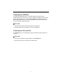
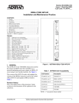
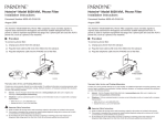
Installing the Power Cord
The POWER port on the unit is a standard, grounded, three-prong connector. The unit
has no power switch.
Figure 1. Hotwire 8300 Endpoint Back Panel
Procedure
1. Insert the power cord’s receptacle into the POWER jack.
2. Plug the other end of the power cord into a grounded power outlet.
3. Check the LEDs.
When power is applied to the unit, the front panel indicators flash for approximately 10 to
15 seconds as the unit initializes itself. The green POWER LED on the front panel
remains on as long as the unit receives power. If the indicator does not light up, check
the power connections and the primary circuit breaker.
Figure 2. Hotwire 8300 Endpoint Front Panel
3
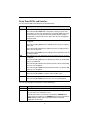
Front Panel LEDs and Switches
The front panel’s LED status indicators are described below:
Indicator Description
MODE
Normally, this indicator lights green.
The indicator lights amber while configuration is being set by the front
panel buttons or when the configuration is changed by SNMP or through
the web interface. The indicator will remain amber until the changed
configuration is saved; it will revert to green when the new configuration
has been saved.
CBR
The indicator is off (not illuminated) when the CBR port has not been
configured.
The indicator lights green when the CBR port link is up and is receiving
AAL1 cells.
The indicator lights red when the CBR port has been configured and no
AAL1 cells are received.
The indicator lights amber when the CBR port link is up but AAL1 cells are
not being received.
NET
The indicator is off (not illuminated) when the Network port has not been
configured.
The indicator lights green when the Network port link is up and the ATM
protocol is established.
The indicator lights red when the Network port link is down and the ATM
protocol is not established.
The indicator lights amber when the Network port link is up, but the ATM
protocol is not established.
ALARM
The indicator lights red if an alarm condition exists.
The indicator lights amber if a “yellow” alarm condition exists.
POWER
The indicator lights green when power is applied to the unit.
The indicator lights amber when the unit is in a test mode loopback.
The user-activated input control buttons are described below:
Button
Description
RESET
Provides a hardware reset to the unit.
CONFIG
Sets the unit back to its factory default Ethernet or HDLC configuration;
this is the same as a maintenance reset.
To initiate this function, you must press and hold the CONFIG button
during a power-up sequence. The CONFIG button must be held until the
MODE LED lights amber and remains illuminated for the default
configuration to take effect.
4
Connecting the Supervisory Port
The SUPERVISORY port is a DB9 female DCE connector configured for 8 bits, no
parity, and 1 stop bit. Bit rates are configured through the Web server interface. The
initial default rate of the Supervisory port is 19200 bps.
On power-up, the Supervisory port sends out diagnostic messages at the bit rate of
115.2 kbps until the Supervisory service acquires the Supervisory port, after which the
port speed is changed to the setting in the Supervisory interface screen.
A VT100 terminal or a PC providing VT100 terminal emulation must be used to set up
access to and management of the unit.
Procedure
1. Configure the PC so it is compatible with the Hotwire 8300 unit:
—
Baud Rate set to 19.2 kbps.
—
Character length set to 8 data bits.
—
Parity set to none.
—
Stop bit set to 1.
—
Flow Control set to None.
2. Insert one end of the DB9-to-DB9 cable into the SUPERVISORY port.
3. Insert the other end of the cable into a COM port on the PC. If there is more than
one COM port, make note of which one you use.
4. Press Enter on the keyboard to display the Main Menu of the VT100 interface. See
the User’s Guide for information about its use.
5
Connecting the Ethernet Port
The unit provides a single Ethernet interface port for IP Gateway, SNMP, and Web
browser access. This interface is an eight-pin modular jack that complies with standard
twisted-pair, 10/100BaseT requirements.
Procedure
1. Insert one 8-pin connector of your Ethernet cable (not provided) into the
10/100_ETHERNET port.
2. Open the supplied ferrite choke and place it around the Ethernet cable as close to
the 8300 Endpoint as possible. Close the choke and lock it by pressing on the latch.
3. Insert the other end of the cable into the Ethernet interface of your LAN.
Ethernet LED Indicators
There are two unlabeled indicator LEDs on either side of the 10/100 ETHERNET jack.
The LED on the left side of the jack pulses amber to indicate data activity (either
transmit or receive). The LED on the right side of the jack lights green to indicate that the
link layer is operational.
Connecting the Serial Port
The SERIAL interface port is a multi-protocol interface presented physically as a DB25
connection. The protocols supported by this interface are RS-232, V.35, EIA-530, X.21,
and RS-449. Refer to the user’s guide for pin assignments.
Procedure
1. Connect the DB25 end of your shielded serial cable to the SERIAL port. Secure it
with its captive screws.
2. Attach and secure to the cable any required adapters, such as for a 34-pin V.35
interface.
3. Plug the other end of the cable into your router and fasten it in place.
6
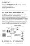
Connecting the CBR Port
The CBR (Constant Bit Rate) port is an RJ48C, eight-pin modular jack that is
software-selectable for T1 or E1. As a T1 port, it terminates as 100 ohms, and as an E1
port at 120 ohms. This port is used to transport TDM traffic using a T1/E1 framer to
provide ATM adaptation Layer 1 with Circuit Emulation Services (AAL1-CES). It must
not be connected to outside plant wiring.
Procedure
1. Plug an RJ48-to-RJ48 cable (not provided) into the CBR port.
2. Plug the other end of the cable into your T1 or E1 equipment.
Connecting the Network Port
The NETWORK port is a standard RJ49C, eight -pin modular jack that terminates as
135 ohms.
Procedure
1. Plug the 8-pin modular cable (provided) into the NETWORK port.
2. Plug the other end of the cable into your DSL interface.
7
Web Interface
If you will use the Ethernet port for the web interface, you must set the IP address of the
port, or use the default address of 192.168.6.1. The IP address of the 8300 Endpoint
must be on the same subnet as the PC accessing the web interface.
Setting the Ethernet Port Address
To set the Ethernet port address:
Procedure
1. Access the Main Menu as described in Connecting the Supervisory Port on page 5.
2. Tab to the Interfaces selection and press Enter. The Interfaces menu appears.
3. Tab to the 10/100 Ethernet selection and press Enter. The IP Details screen
appears.
4. Enter an IP Address, Subnet Mask, and Gateway Address.
5. Tab to Save & Restart and press Enter. When the verification screen appears,
select Yes.
8
Accessing the Web Interface
To access the web interface:
Procedure
1. Start your web browser. Microsoft Internet Explorer version 5.0 or higher is
recommended.
2. Type the IP address of the 8300 Endpoint’s Ethernet port into the Address field of
the browser and press Enter. The Unit Screen appears.
Click on the selections in the navigation frame on the left side of the screen to configure
and monitor the unit. See the User’s Guide for more information.
9
!
UNITED STATES – EMI NOTICE:
This equipment has been tested and found to comply with the limits for a Class A digital
device, pursuant to Part 15 of the FCC rules. These limits are designed to provide
reasonable protection against harmful interference when the equipment is operated in a
commercial environment. This equipment generates, uses, and can radiate radio
frequency energy and, if not installed and used in accordance with the instruction
manual, may cause harmful interference to radio communications. Operation of this
equipment in a residential area is likely to cause harmful interference in which case the
user will be required to correct the interference at his own expense.
The authority to operate this equipment is conditioned by the requirements that no
modifications will be made to the equipment unless the changes or modifications are
expressly approved by Paradyne Corporation.
If the equipment includes a ferrite choke or chokes, they must be installed per the
installation instructions.
Notice to Users of the United States Telephone Network
This equipment complies with Part 68 of the FCC rules and the requirements adopted
by the Administrative Council for Terminal Attachment (ACTA). On the bottom side of
this equipment is a label that contains, among other information, a product identifier in
the format US:AAAEQ##TXXXX. If requested, this number must be provided to the
Telephone Company.
This equipment is intended to connect to the Telephone Network through a Universal
Service Order Code (USOC) type RJ49C. A plug and jack used to connect this
equipment to the premises wiring and telephone network must comply with the
applicable FCC Part 68 rules and requirements adopted by the ACTA. A compliant
telephone cord and modular plug is provided with this product. It has been designed to
be connected to a compatible modular jack that is also compliant.
The Ringer Equivalence Number (or REN) is used to determine the number of devices
that may be connected to a telephone line. Excessive RENs on a telephone line may
result in the devices not ringing in response to an incoming call. In most but not all
areas, the sum of RENs should not exceed five (5.0). To be certain of the number of
devices that may be connected to a line, as determined by the total RENs, contact the
local Telephone Company. The REN for this product is part of the product identifier that
has the format US:AAAEQ##TXXXX. The digits represented by ## are the REN without
a decimal point. For example, 03 represents a REN of 0.3. The characters NAN mean
that the REN is not applicable since the equipment may not be used on a telephone line
that provides dial up service.
If the 8300 Endpoint causes harm to the telephone network, the Telephone Company
will notify you in advance that temporary discontinuance of service may be required.
But if advance notice is not practical, the Telephone Company will notify the customer as
soon as possible. Also, you will be advised of your right to file a complaint with the FCC
if you believe it is necessary.
10
The Telephone Company may make changes in its facilities, equipment, operations or
procedures that could affect the operation of the equipment. If this happens, the
Telephone Company will provide advance notice in order for you to make necessary
modifications to maintain uninterrupted service.
If trouble is experienced with the 8300 Endpoint, refer to the repair and warranty
information in this document.
If the equipment is causing harm to the telephone network, the Telephone Company
may request that you disconnect the equipment until the problem is resolved.
The user may make no repairs to the equipment.
Connection to party line service is subject to state tariffs. Contact the state public utility
commission, public service commission or corporation commission for information.
If the site has specially wired alarm equipment connected to the telephone line, ensure
the installation of the 8300 Endpoint does not disable the alarm equipment. If you have
questions about what will disable alarm equipment, consult your Telephone Company or
a qualified installer.
!
CANADA – EMI NOTICE:
This Class A digital apparatus meets all requirements of the Canadian
interference-causing equipment regulations.
Cet appareil numérique de la classe A respecte toutes les exigences du réglement sur
le matérial brouilleur du Canada.
Notices to Users of the Canadian Telephone Network
NOTICE: This equipment meets the applicable Industry Canada Terminal Equipment
Technical Specifications. This is confirmed by the registration number. The abbreviation
IC before the registration number signifies that registration was performed based on a
Declaration of Conformity indicating that Industry Canada technical specifications were
met. It does not imply that Industry Canada approved the equipment.
NOTICE: The Ringer Equivalence Number (REN) for this terminal equipment is labeled
on the equipment and includes the effect of the POTS splitter. The REN assigned to
each terminal equipment provides an indication of the maximum number of terminals
allowed to be connected to a telephone interface. The termination on an interface may
consist of any combination of devices subject only to the requirement that the sum of the
Ringer Equivalence Numbers of all the devices does not exceed five.
CE Marking
When the product is marked with the CE mark on the equipment label, a supporting
Declaration of Conformity may be downloaded from the Paradyne World Wide Web site
at www.paradyne.com. Select Library
Technical Manuals
CE Declarations of
Conformity.
→
→
11
!
Important Safety Instructions
1. Read and follow all warning notices and instructions marked on the product or
included in the manual.
2. This product is intended to be used with a 3-wire grounding type plug — a plug
which has a grounding pin. This is a safety feature. Equipment grounding is vital to
ensure safe operation. Do not defeat the purpose of the grounding type plug by
modifying the plug or using an adapter.
Prior to installation, use an outlet tester or a voltmeter to check the AC receptacle
for the presence of earth ground. If the receptacle is not properly grounded, the
installation must not continue until a qualified electrician has corrected the problem.
If a 3-wire grounding type power source is not available, consult a qualified
electrician to determine another method of grounding the equipment.
3. Slots and openings in the cabinet are provided for ventilation. To ensure reliable
operation of the product and to protect it from overheating, these slots and
openings must not be blocked or covered.
4. Do not allow anything to rest on the power cord and do not locate the product where
persons will walk on the power cord.
5. Do not attempt to service this product yourself, as opening or removing covers may
expose you to dangerous high voltage points or other risks. Refer all servicing to
qualified service personnel.
6. General purpose cables are described for use with this product. Special cables,
which may be required by the regulatory inspection authority for the installation site,
are the responsibility of the customer. To reduce the risk of fire, use a UL Listed or
CSA Certified, minimum 26 AWG (0.129 mm2) telecommunication cable.
7. When installed in the final configuration, the product must comply with the
applicable Safety Standards and regulatory requirements of the country in which it
is installed. If necessary, consult with the appropriate regulatory agencies and
inspection authorities to ensure compliance.
8. A rare phenomenon can create a voltage potential between the earth grounds of
two or more buildings. If products installed in separate buildings are
interconnected, the voltage potential may cause a hazardous condition. Consult a
qualified electrical consultant to determine whether or not this phenomenon exists
and, if necessary, implement corrective action prior to interconnecting the products.
9. In addition, if the equipment is to be used with telecommunications circuits, take the
following precautions:
— Never install telephone wiring during a lightning storm.
—
Never install telephone jacks in wet locations unless the jack is specifically
designed for wet locations.
—
Never touch uninsulated telephone wires or terminals unless the telephone line
has been disconnected at the network interface.
—
—
Use caution when installing or modifying telephone lines.
Avoid using a telephone (other than a cordless type) during an electrical storm.
There may be a remote risk of electric shock from lightning.
Do not use the telephone to report a gas leak in the vicinity of the leak.
—
12
10. This unit is provided with a replaceable lithium battery. Replace the battery only with
the same type recommended by the manufacturer. Discard used batteries
according to the manufacturer’s instructions.
Supplier’s Declaration of Conformity
Place of Issue: Paradyne Corporation
8545 126th Avenue North
Largo, FL 33773-1502
USA
Date of Issue:
4/4/2003
Paradyne Corporation, located at the above address, hereby certifies that the Hotwire®
Model Number 8300-AX-400, bearing labeling identification number
US:AW2DLNAN8300-AX complies with: the Federal Communications Commission's
("FCC") Rules and Regulations 47 CFR Part 68, the Administrative Council on Terminal
Attachments ("ACTA")-adopted technical criteria: TIA-968-A, "Telecommunications Telephone Terminal Equipment -Technical Requirements for Connection of Terminal
Equipment To the Telephone Network, October 2002" and T1.TRQ.6-2001, "Technical
Requirements for SHDSL, HDSL2, HDSL4 Digital Subscriber Line Terminal Equipment
to Prevent Harm to the Telephone Network."
Patrick Murphy
Senior Vice President, Chief Financial Officer
Warranty, Sales, Service, and Training Information
Contact your local sales representative, service representative, or distributor directly for
any help needed. For additional information concerning warranty, sales, service, repair,
installation, documentation, training, distributor locations, or Paradyne worldwide office
locations, use one of the following methods:
Internet: Visit the Paradyne World Wide Web site at www.paradyne.com. (Be
sure to register your warranty at www.paradyne.com/warranty.)
Telephone: Call our automated system to receive current information by fax or to
speak with a company representative.
—
Within the U.S.A., call 1-800-870-2221
—
Outside the U.S.A., call 1-727-530-2340
13
Document Feedback
We welcome your comments and suggestions about this document. Please mail them to
Technical Publications, Paradyne Corporation, 8545 126th Ave. N., Largo, FL 33773, or
send e-mail to [email protected]. Include the number and title of this document
in your correspondence. Please include your name and phone number if you are willing
to provide additional information.
Trademarks
FrameSaver is a registered trademark of Paradyne Corporation. All other products and
services mentioned herein are the trademarks, service marks, registered trademarks, or
registered service marks of their respective owners.
Copyright © 2003 Paradyne Corporation. Printed in U.S.A.
14
15
*8300-A2-GN10-00*
*8300-A2-GN10-00*
16