1
COMSPHERE
3800 SERIES MODEMS
MODELS 3810, 3811, AND 3820
USER’S GUIDE
Document No. 3810-A2-GB30-20
November 1996
COMSPHERE 3800 Series Modems
COMSPHERE
3800 Series Modems
Models 3810, 3811, and 3820
User’s Guide
3810-A2-GB30-20
3rd Edition (November 1996)
Changes and enhancements to the product and to the information herein will be documented and issued as a new release.
For the 3800 Series standalone modems, the Universal Service Order Code (USOC) for Permissive mode is RJ11C and for
Programmable mode is RJ41S or RJ45S. The Canadian equivalent to the USOC is CA11 for RJ11C, and CA41A and
CA45A for RJ41S and RJ45S, respectively. For 3800 Series carrier-mounted modems, the USOC for Permissive mode is
RJ21X and for Programmable mode is RJ27X. The Canadian equivalent to the USOC is CA21A for RJ21X and CA27A
for RJ27X.
Warranty, Sales, and Service Information
Contact your sales or service representative directly for any help needed. For additional information concerning warranty,
sales, service, repair, installation, documentation or training, use one of the following methods:
• Via the Internet: Visit the Paradyne World Wide Web site at http://www.paradyne.com
• Via Telephone: Call our automated call system to receive current information via fax or to speak with a company
representative.
— Within the U.S.A., call 1-800-870-2221
— International, call 813-530-2340
Trademarks
All products and services mentioned herein are the trademarks, service marks, registered trademarks or registered service marks of their
respective owners.
Printed on recycled paper
COPYRIGHT E 1996 Paradyne Corporation. All rights reserved.
This publication is protected by federal copyright law. No part of this publication may be copied or distributed, transmitted, transcribed, stored in a retrieval system,
or translated into any human or computer language in any form or by any means, electronic, mechanical, magnetic, manual or otherwise, or disclosed to third parties
without the express written permission of Paradyne Corporation, 8545 126th Avenue North, P.O. Box 2826, Largo, Florida 33779-2826.
Paradyne Corporation makes no representation or warranties with respect to the contents hereof and specifically disclaims any implied warranties of merchantability
or fitness for a particular purpose. Further, Paradyne Corporation reserves the right to revise this publication and to make changes from time to time in the contents
hereof without obligation of Paradyne Corporation to notify any person of such revision or changes.
A
November 1996
3810-A2-GB30-20
Safety Instructions
Important Safety Instructions
1.
Read and follow all warning notices and instructions marked on the product or included in the
manual.
2.
This product is intended to be used with a three-wire grounding type plug – a plug which has
a grounding pin. This is a safety feature. Equipment grounding is vital to ensure safe
operation. Do not defeat the purpose of the grounding type plug by modifying the plug or
using an adapter.
Prior to installation, use an outlet tester or a voltmeter to check the ac receptacle for the
presence of earth ground. If the receptacle is not properly grounded, the installation must not
continue until a qualified electrician has corrected the problem.
If a three-wire grounding type power source is not available, consult a qualified electrician to
determine another method of grounding the equipment.
3.
Slots and openings in the cabinet are provided for ventilation. To ensure reliable operation of
the product and to protect it from overheating, these slots and openings must not be blocked
or covered.
4.
Do not allow anything to rest on the power cord and do not locate the product where persons
will walk on the power cord.
5.
Do not attempt to service this product yourself, as opening or removing covers may expose
you to dangerous high voltage points or other risks. Refer all servicing to qualified service
personnel.
6.
General purpose cables are provided with this product. Special cables, which may be required
by the regulatory inspection authority for the installation site, are the responsibility of the
customer.
7.
When installed in the final configuration, the product must comply with the applicable Safety
Standards and regulatory requirements of the country in which it is installed. If necessary,
consult with the appropriate regulatory agencies and inspection authorities to ensure
compliance.
8.
A rare phenomenon can create a voltage potential between the earth grounds of two or more
buildings. If products installed in separate buildings are interconnected, the voltage potential
may cause a hazardous condition. Consult a qualified electrical consultant to determine
whether or not this phenomenon exists and, if necessary, implement corrective action prior to
interconnecting the products.
In addition, if the equipment is to be used with telecommunications circuits, take the following
precautions:
–
–
–
–
–
–
3810-A2-GB30-20
Never install telephone wiring during a lightning storm.
Never install telephone jacks in wet locations unless the jack is specifically designed for wet
locations.
Never touch uninsulated telephone wires or terminals unless the telephone line has been
disconnected at the network interface.
Use caution when installing or modifying telephone lines.
Avoid using a telephone (other than a cordless type) during an electrical storm.
There may be a remote risk of electric shock from lightning.
Do not use the telephone to report a gas leak in the vicinity of the leak.
November 1996
B
COMSPHERE 3800 Series Modems
Notices
WARNING
THIS EQUIPMENT HAS BEEN TESTED AND FOUND TO COMPLY WITH THE LIMITS FOR A CLASS A DIGITAL DEVICE,
PURSUANT TO PART 15 OF THE FCC RULES. THESE LIMITS ARE DESIGNED TO PROVIDE REASONABLE
PROTECTION AGAINST HARMFUL INTERFERENCE WHEN THE EQUIPMENT IS OPERATED IN A COMMERCIAL
ENVIRONMENT. THIS EQUIPMENT GENERATES, USES, AND CAN RADIATE RADIO FREQUENCY ENERGY AND, IF
NOT INSTALLED AND USED IN ACCORDANCE WITH THE INSTRUCTION MANUAL, MAY CAUSE HARMFUL
INTERFERENCE TO RADIO COMMUNICATIONS. OPERATION OF THIS EQUIPMENT IN A RESIDENTIAL AREA IS
LIKELY TO CAUSE HARMFUL INTERFERENCE IN WHICH CASE THE USER WILL BE REQUIRED TO CORRECT THE
INTERFERENCE AT HIS OWN EXPENSE.
THE AUTHORITY TO OPERATE THIS EQUIPMENT IS CONDITIONED BY THE REQUIREMENTS THAT NO
MODIFICATIONS WILL BE MADE TO THE EQUIPMENT UNLESS THE CHANGES OR MODIFICATIONS ARE EXPRESSLY
APPROVED BY PARADYNE.
WARNING
TO USERS OF DIGITAL APPARATUS IN CANADA:
THIS CLASS A DIGITAL APPARATUS MEETS ALL REQUIREMENTS OF THE CANADIAN INTERFERENCE-CAUSING
EQUIPMENT REGULATIONS.
CET APPAREIL NUMÉRIQUE DE LA CLASSE A RESPECTE TOUTES LES EXIGENCES DU RÈGLEMENT SUR LE
MATÉRIEL BROUILLEUR DU CANADA.
The following warning applies to all Model 3811 modems.
WARNING
THE MODEL 3811 IS PROVIDED WITH A REPLACEABLE LITHIUM BATTERY. REPLACE THE BATTERY ONLY WITH
THE SAME TYPE RECOMMENDED BY THE MANUFACTURER. DISCARD USED BATTERIES ACCORDING TO THE
MANUFACTURER’S INSTRUCTIONS.
LE MODÈLE 3811 EST FOURNI AVEC UNE PILE AU LITHIUM REMPLAÇABLE REMPLACER UNIQUEMENT AVEC
UNE BATTERIE DU MÊME TYPE OU D’UN TYPE RECOMMANDÉ PAR LE CONSTRUCTEUR. METTRE AU RÉBUT
LES BATTERIES USAGÉES CONFORMÉMENT AUX INSTRUCTIONS DU FABRICANT.
C
November 1996
3810-A2-GB30-20
Safety Instructions
Government Requirements and Equipment Return
Certain governments require that instructions pertaining to modem connection to the public switched
telephone network be included in the installation and operation manual. Specific instructions are
listed in the following sections.
United States
Notice to Users of the Public Switched Telephone Network
1. This equipment complies with Part 68 of the FCC rules. On the equipment is a label that contains,
among other information, the FCC registration number and ringer equivalence number (REN) for
this equipment. The label is located on the bottom of the Model 3810 and 3820 modems. This label
is located on the Model 3811’s circuit card assembly. If requested, this information must be
provided to the telephone company.
2. Page A of this manual contains the Universal Service Order Codes (USOC) associated with the
services on which the equipment is to be connected.
3. The Ringer Equivalence (REN) is used to determine the quantity of devices which may be
connected to the telephone line. Excessive RENs on the telephone line may result in the devices
not ringing in response to an incoming call. In most, but not all areas, the sum of the RENs should
not exceed five (5.0). To be certain of the number of devices that may be connected to the line, as
determined by the total RENs, contact the telephone company to determine the maximum RENs
for the calling area.
4. If the 3800 Series modem causes harm to the telephone network, the telephone company will
notify you in advance that temporary discontinuance of service may be required. But if advance
notice is not practical, the telephone company will notify the customer as soon as possible. Also,
you will be advised of your right to file a complaint with the FCC if you believe it is necessary.
5. The telephone company may make changes in its facilities, equipment, operations, or procedures
that could affect the operation of the equipment. If this happens, the telephone company will
provide advance notice in order for you to make the necessary modifications in order to maintain
uninterrupted service.
6. If you experience trouble with this equipment, please contact your sales or service representative (as
appropriate) for repair or warranty information. If the product needs to be returned to the company service
center for repair, contact them directly for return instructions using one of the following methods:
• Via the Internet: Visit the Paradyne World Wide Web site at http://www.paradyne.com
• Via Telephone: Call our automated call system to receive current information via fax or to speak with
a company representative.
— Within the U.S.A., call 1-800-870-2221
— International, call 813-530-2340
If the trouble is causing harm to the telephone network, the telephone company may request that you
remove the equipment from the network until the problem is resolved.
7. The user is not authorized to repair or modify the equipment.
3810-A2-GB30-20
November 1996
D
COMSPHERE 3800 Series Modems
8. This equipment cannot be used on public coin service provided by the telephone company.
Connection to Party Line Service is subject to state tariffs. (Contact the state public utility
commission, public service commission or corporation commission for information.)
9. The Telephone Consumer Protection Act of 1991 makes it unlawful for any person to use a
computer or other electronic device to send any message via a telephone fax machine unless such a
message clearly contains, in a margin at the top or bottom of each transmitted page, or on the first
page of the transmission, the date and time it is sent, and an identification of the business, or other
entity, or other individual sending the message, and the telephone number of such business, or
other entity, or individual.
In order to program this information, follow the steps outlined in the manual supplied with your
fax software.
10. An FCC compliant telephone cord with modular plugs may be provided with this equipment. This
equipment is designed to be connected to the telephone network or premises wiring using a
compatible modular jack which is Part 68 compliant.
Canada
Notice to Users of the Canadian Public Switched Telephone Network
The Canadian Department of Communications label identifies certified equipment. This certification
means that the equipment meets certain telecommunications network protective, operational and
safety requirements. The Department does not guarantee the equipment will operate to the user’s
satisfaction.
Before installing this equipment, users should ensure that it is permissible to be connected to the
facilities of the local telecommunications company. The equipment must also be installed using an
acceptable method of connection. In some cases, the company’s inside wiring associated with a single
line individual service may be extended by means of a certified connector assembly (telephone
extension cord). The customer should be aware that compliance with the above conditions may not
prevent degradation of service in some situations.
E
November 1996
3810-A2-GB30-20
Safety Instructions
Repairs to certified equipment should be made by an authorized Canadian maintenance facility
designated by the supplier. Any repairs or alterations made by the user to this equipment, or
equipment malfunctions, may give the telecommunications company cause to request the user to
disconnect the equipment.
Users should ensure for their own protection that the electrical ground connections of the power
utility, telephone line and internal metallic water pipe system, if present, are connected together. This
precaution may be particularly important in rural areas.
CAUTION
Users should not attempt to make such connections themselves, but
should contact the appropriate electric inspection authority, or
electrician, as appropriate.
The Load Number for this equipment is listed on the label on the modem. The Load Number (LN)
assigned to each terminal device denotes the percentage of the total load to be connected to a
telephone loop which is used by the device to prevent overloading. The termination on a loop may
consist of any combination of devices subject only to the requirement that the total of the Load
Numbers of all devices does not exceed 100.
If your equipment is in need of repair, refer to the procedures described on page A in the front of this
document for contact information.
3810-A2-GB30-20
November 1996
F
Table of Contents
Preface
Objectives and Reader Assumptions . . . . . . . . . . . . . . . . . . . . . . . . . . . vii
How to Use This Manual . . . . . . . . . . . . . . . . . . . . . . . . . . . . . . . . . . . . vii
Related Documents . . . . . . . . . . . . . . . . . . . . . . . . . . . . . . . . . . . . . . . . vii
1. Introduction
Overview . . . . . . . . . . . . . . . . . . . . . . . . . . . . . . . . . . . . . . . . . . . . . . . .
Features . . . . . . . . . . . . . . . . . . . . . . . . . . . . . . . . . . . . . . . . . . . . . . . . .
Options . . . . . . . . . . . . . . . . . . . . . . . . . . . . . . . . . . . . . . . . . . . . . . . . . .
COMSPHERE 3800 Series Models . . . . . . . . . . . . . . . . . . . . . . . . . . . .
1-1
1-2
1-2
1-2
2. Model 3810 and 3820 Installation
Overview . . . . . . . . . . . . . . . . . . . . . . . . . . . . . . . . . . . . . . . . . . . . . . . .
3800 Series Modem Package . . . . . . . . . . . . . . . . . . . . . . . . . . . . . . . . .
Model 3810 or Model 3820 Modem Installation . . . . . . . . . . . . . . . . . .
DTE Connection . . . . . . . . . . . . . . . . . . . . . . . . . . . . . . . . . . . . . . . . . .
Dial Network Connection . . . . . . . . . . . . . . . . . . . . . . . . . . . . . . . . . . .
Model 3810 Dial-Line Connection . . . . . . . . . . . . . . . . . . . . . . . . . . . .
Model 3820 Dial-Line Connection . . . . . . . . . . . . . . . . . . . . . . . . . . . .
Model 3810 4-Wire/2-Wire Leased-Line Connection . . . . . . . . . . . . . .
Model 3820 2-Wire Leased-Line Connection . . . . . . . . . . . . . . . . . . . .
Model 3810 and Model 3820 Telephone Connection . . . . . . . . . . . . . .
Dial Network Management System Connection . . . . . . . . . . . . . . . . . .
AC Power Transformer Connection . . . . . . . . . . . . . . . . . . . . . . . . . . .
Modem Power-Up . . . . . . . . . . . . . . . . . . . . . . . . . . . . . . . . . . . . . . . . .
Removing and Replacing Model 3810 and Model 3820 Modems . . . .
2-1
2-2
2-3
2-4
2-6
2-6
2-6
2-7
2-7
2-7
2-7
2-7
2-8
2-8
3. Model 3811 Installation
Overview . . . . . . . . . . . . . . . . . . . . . . . . . . . . . . . . . . . . . . . . . . . . . . . . 3-1
Model 3811 Installation . . . . . . . . . . . . . . . . . . . . . . . . . . . . . . . . . . . . . 3-2
Removing and Replacing Model 3811 Modems . . . . . . . . . . . . . . . . . . 3-4
3810-A2-GB30-20
November 1996
i
COMSPHERE 3800 Series Modems
4. DCP Operation
Overview . . . . . . . . . . . . . . . . . . . . . . . . . . . . . . . . . . . . . . . . . . . . . . . .
Diagnostic Control Panels . . . . . . . . . . . . . . . . . . . . . . . . . . . . . . . . . . .
Status Indicators . . . . . . . . . . . . . . . . . . . . . . . . . . . . . . . . . . . . . . . . . . .
Diagnostic Control Panel Operation . . . . . . . . . . . . . . . . . . . . . . . . . . .
Menu Structure . . . . . . . . . . . . . . . . . . . . . . . . . . . . . . . . . . . . . . . . . . . .
Selecting Factory Configuration Options . . . . . . . . . . . . . . . . . . . . . . .
Diagnostic Control Panel Security Access . . . . . . . . . . . . . . . . . . . . . .
4-1
4-1
4-4
4-6
4-7
4-13
4-15
5. Call Setup Branch
Overview . . . . . . . . . . . . . . . . . . . . . . . . . . . . . . . . . . . . . . . . . . . . . . . . 5-1
Call Setup Branch . . . . . . . . . . . . . . . . . . . . . . . . . . . . . . . . . . . . . . . . . 5-2
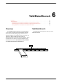
6. Talk/Data Branch
Overview . . . . . . . . . . . . . . . . . . . . . . . . . . . . . . . . . . . . . . . . . . . . . . . . 6-1
Talk/Data Branch . . . . . . . . . . . . . . . . . . . . . . . . . . . . . . . . . . . . . . . . . . 6-1
7. Status Branch
Overview . . . . . . . . . . . . . . . . . . . . . . . . . . . . . . . . . . . . . . . . . . . . . . . . 7-1
Status Branch . . . . . . . . . . . . . . . . . . . . . . . . . . . . . . . . . . . . . . . . . . . . . 7-2
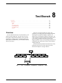
8. Test Branch
Overview . . . . . . . . . . . . . . . . . . . . . . . . . . . . . . . . . . . . . . . . . . . . . . . . 8-1
Test Branch . . . . . . . . . . . . . . . . . . . . . . . . . . . . . . . . . . . . . . . . . . . . . . 8-2
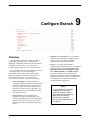
9. Configure Branch
Overview . . . . . . . . . . . . . . . . . . . . . . . . . . . . . . . . . . . . . . . . . . . . . . . .
Configure Branch . . . . . . . . . . . . . . . . . . . . . . . . . . . . . . . . . . . . . . . . . .
Configuration Tables . . . . . . . . . . . . . . . . . . . . . . . . . . . . . . . . . . . . . . .
Security Configuration Options . . . . . . . . . . . . . . . . . . . . . . . . . . . . . . .
9-1
9-4
9-7
9-46
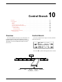
10. Control Branch
Overview . . . . . . . . . . . . . . . . . . . . . . . . . . . . . . . . . . . . . . . . . . . . . . . . 10-1
Control Branch . . . . . . . . . . . . . . . . . . . . . . . . . . . . . . . . . . . . . . . . . . . . 10-1
Automatic Firmware Download . . . . . . . . . . . . . . . . . . . . . . . . . . . . . . 10-6
11. Remote Branch
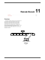
Overview . . . . . . . . . . . . . . . . . . . . . . . . . . . . . . . . . . . . . . . . . . . . . . . . 11-1
Remote Branch . . . . . . . . . . . . . . . . . . . . . . . . . . . . . . . . . . . . . . . . . . . . 11-2
ii
November 1996
3810-A2-GB30-20
Table of Contents
12. Security
Overview . . . . . . . . . . . . . . . . . . . . . . . . . . . . . . . . . . . . . . . . . . . . . . . .
Security Branch . . . . . . . . . . . . . . . . . . . . . . . . . . . . . . . . . . . . . . . . . . .
Security Password Entry Techniques . . . . . . . . . . . . . . . . . . . . . . . . . . .
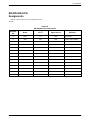
Database Table Examples . . . . . . . . . . . . . . . . . . . . . . . . . . . . . . . . . . .
12-1
12-4
12-11
12-12
13. Fax Operation
Overview . . . . . . . . . . . . . . . . . . . . . . . . . . . . . . . . . . . . . . . . . . . . . . . . 13-1
Fax Operation . . . . . . . . . . . . . . . . . . . . . . . . . . . . . . . . . . . . . . . . . . . . . 13-1
14. AT Command Set and S-Registers
Overview . . . . . . . . . . . . . . . . . . . . . . . . . . . . . . . . . . . . . . . . . . . . . . . .
Operating Modes . . . . . . . . . . . . . . . . . . . . . . . . . . . . . . . . . . . . . . . . . .
Command Guidelines . . . . . . . . . . . . . . . . . . . . . . . . . . . . . . . . . . . . . . .
AT Command List . . . . . . . . . . . . . . . . . . . . . . . . . . . . . . . . . . . . . . . . .
S-Register List . . . . . . . . . . . . . . . . . . . . . . . . . . . . . . . . . . . . . . . . . . . .
14-1
14-1
14-2
14-2
14-15
A.
B.
C.
D.
E.
F.
G.
H.
A-1
B-1
C-1
D-1
E-1
F-1
G-1
H-1
Appendices
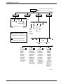
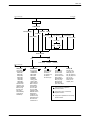
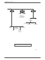
Menu Tree . . . . . . . . . . . . . . . . . . . . . . . . . . . . . . . . . . . . . . . . . . .
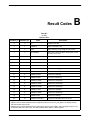
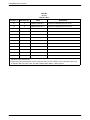
Result Codes . . . . . . . . . . . . . . . . . . . . . . . . . . . . . . . . . . . . . . . . .
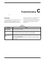
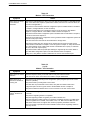
Troubleshooting . . . . . . . . . . . . . . . . . . . . . . . . . . . . . . . . . . . . . . .
Technical Specifications . . . . . . . . . . . . . . . . . . . . . . . . . . . . . . . .
Pin Assignments . . . . . . . . . . . . . . . . . . . . . . . . . . . . . . . . . . . . . . .
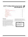
CCITT V.25bis Dialing Commands and Response . . . . . . . . . . . .
Default Configuration Options . . . . . . . . . . . . . . . . . . . . . . . . . . .
Equipment List . . . . . . . . . . . . . . . . . . . . . . . . . . . . . . . . . . . . . . . .
Glossary
Index
3810-A2-GB30-20
November 1996
iii
COMSPHERE 3800 Series Modems
List of Figures
Figure
2-1
2-2
2-3
3-1
3-2
3-3
4-1
4-2
4-3
4-4
5-1
8-1
8-2
8-3
8-4
8-5
8-6
9-1
9-2
11-1
E-1
iv
Page
Model 3810 and 3820 . . . . . . . . . . . . . . . . . . . . . . . . . . . . . . . . . . . . . . . . . . . . . . . .
Model 3810 Rear Panel . . . . . . . . . . . . . . . . . . . . . . . . . . . . . . . . . . . . . . . . . . . . . . .
Model 3820 Rear Panel . . . . . . . . . . . . . . . . . . . . . . . . . . . . . . . . . . . . . . . . . . . . . . .
Model 3811 . . . . . . . . . . . . . . . . . . . . . . . . . . . . . . . . . . . . . . . . . . . . . . . . . . . . . . . .
Installing a Model 3811 Modem . . . . . . . . . . . . . . . . . . . . . . . . . . . . . . . . . . . . . . . .
Circuit Pack Lock . . . . . . . . . . . . . . . . . . . . . . . . . . . . . . . . . . . . . . . . . . . . . . . . . . .
Model 3810 DCP . . . . . . . . . . . . . . . . . . . . . . . . . . . . . . . . . . . . . . . . . . . . . . . . . . . .
Model 3820 DCP . . . . . . . . . . . . . . . . . . . . . . . . . . . . . . . . . . . . . . . . . . . . . . . . . . . .
Optional SDCP, Model 3811 Faceplate, and Optional SDU . . . . . . . . . . . . . . . . . . .
3800 Series LCD and Keypad . . . . . . . . . . . . . . . . . . . . . . . . . . . . . . . . . . . . . . . . . .
Dial Backup . . . . . . . . . . . . . . . . . . . . . . . . . . . . . . . . . . . . . . . . . . . . . . . . . . . . . . . .
Local Analog Loopback . . . . . . . . . . . . . . . . . . . . . . . . . . . . . . . . . . . . . . . . . . . . . . .
Remote Digital Loopback . . . . . . . . . . . . . . . . . . . . . . . . . . . . . . . . . . . . . . . . . . . . .
Local Digital Loopback . . . . . . . . . . . . . . . . . . . . . . . . . . . . . . . . . . . . . . . . . . . . . . .
Pattern Test and Local Analog Loopback Test . . . . . . . . . . . . . . . . . . . . . . . . . . . . .
Pattern Test and Remote Digital Loopback Test . . . . . . . . . . . . . . . . . . . . . . . . . . . .
End-to-End Pattern Test . . . . . . . . . . . . . . . . . . . . . . . . . . . . . . . . . . . . . . . . . . . . . . .
DCP Configuration Process . . . . . . . . . . . . . . . . . . . . . . . . . . . . . . . . . . . . . . . . . . . .
AT Command Configuration Process . . . . . . . . . . . . . . . . . . . . . . . . . . . . . . . . . . . .
Top-Level Menu of a Remote 3800 Series Modem . . . . . . . . . . . . . . . . . . . . . . . . . .
Wiring Diagram – 8-Position to 6-Position Crossover Cable . . . . . . . . . . . . . . . . . .
November 1996
2-2
2-4
2-5
3-2
3-3
3-4
4-2
4-2
4-3
4-6
5-4
8-3
8-4
8-5
8-6
8-6
8-7
9-2
9-3
11-3
E-4
3810-A2-GB30-20
Table of Contents
List of Tables
Tables
4-1
4-2
4-3
4-4
4-5
4-6
5-1
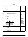
9-1
9-2
9-3
9-4
9-5
9-6
9-7
9-8
9-9
12-1
12-2
12-3
12-4
12-5
12-6
12-7
14-1
14-2
B-1
C-1
C-2
C-3
C-4
C-5
C-6
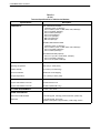
D-1
E-1
E-2
E-3
E-4
F-1
F-2
G-1
3810-A2-GB30-20
Page
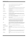
Model 3810 and Model 3811 DCP LEDs . . . . . . . . . . . . . . . . . . . . . . . . . . . . . . . . .
Model 3820 DCP LEDs . . . . . . . . . . . . . . . . . . . . . . . . . . . . . . . . . . . . . . . . . . . . . . .
SDCP LEDs . . . . . . . . . . . . . . . . . . . . . . . . . . . . . . . . . . . . . . . . . . . . . . . . . . . . . . . .
Top-Level Menu Status . . . . . . . . . . . . . . . . . . . . . . . . . . . . . . . . . . . . . . . . . . . . . . .
Common Operational Messages . . . . . . . . . . . . . . . . . . . . . . . . . . . . . . . . . . . . . . . .
Dial Access Security Messages . . . . . . . . . . . . . . . . . . . . . . . . . . . . . . . . . . . . . . . . .
Valid Dial Command Modifiers . . . . . . . . . . . . . . . . . . . . . . . . . . . . . . . . . . . . . . . . .
DTE Interface Configuration Options . . . . . . . . . . . . . . . . . . . . . . . . . . . . . . . . . . . .
DTE Dialer Configuration Options . . . . . . . . . . . . . . . . . . . . . . . . . . . . . . . . . . . . . .
Line Dialer Configuration Options . . . . . . . . . . . . . . . . . . . . . . . . . . . . . . . . . . . . . .
Dial Line Configuration Options . . . . . . . . . . . . . . . . . . . . . . . . . . . . . . . . . . . . . . . .
Leased Line Configuration Options . . . . . . . . . . . . . . . . . . . . . . . . . . . . . . . . . . . . . .
V.42/MNP/Buffer Configuration Options . . . . . . . . . . . . . . . . . . . . . . . . . . . . . . . . .
Test Configuration Options . . . . . . . . . . . . . . . . . . . . . . . . . . . . . . . . . . . . . . . . . . . .
Miscellaneous Configuration Options . . . . . . . . . . . . . . . . . . . . . . . . . . . . . . . . . . . .
Security Configuration Options . . . . . . . . . . . . . . . . . . . . . . . . . . . . . . . . . . . . . . . . .
Edit Password Table Group Options . . . . . . . . . . . . . . . . . . . . . . . . . . . . . . . . . . . . .
Set Answer Security Group Options . . . . . . . . . . . . . . . . . . . . . . . . . . . . . . . . . . . . .
Set Originate Security Group Options . . . . . . . . . . . . . . . . . . . . . . . . . . . . . . . . . . . .
Security Database Table Using VF-Side Passwords . . . . . . . . . . . . . . . . . . . . . . . . .
Security Database Table Using DTE-Side Passwords . . . . . . . . . . . . . . . . . . . . . . . .
Security Database Table Using Both VF-Side and DTE-Side Passwords . . . . . . . . .
Security Database Table Using Paired VF-Side and DTE-Side Passwords . . . . . . .
3800 Series AT Commands . . . . . . . . . . . . . . . . . . . . . . . . . . . . . . . . . . . . . . . . . . . .
3800 Series S-Registers . . . . . . . . . . . . . . . . . . . . . . . . . . . . . . . . . . . . . . . . . . . . . . .
Result Codes . . . . . . . . . . . . . . . . . . . . . . . . . . . . . . . . . . . . . . . . . . . . . . . . . . . . . . .
Modem Health . . . . . . . . . . . . . . . . . . . . . . . . . . . . . . . . . . . . . . . . . . . . . . . . . . . . . .
Modem – DTE Connection . . . . . . . . . . . . . . . . . . . . . . . . . . . . . . . . . . . . . . . . . . . .
Modem – VF Connection . . . . . . . . . . . . . . . . . . . . . . . . . . . . . . . . . . . . . . . . . . . . . .
Online Operation . . . . . . . . . . . . . . . . . . . . . . . . . . . . . . . . . . . . . . . . . . . . . . . . . . . .
Leased-Line Operation . . . . . . . . . . . . . . . . . . . . . . . . . . . . . . . . . . . . . . . . . . . . . . . .
Dial Backup Operation . . . . . . . . . . . . . . . . . . . . . . . . . . . . . . . . . . . . . . . . . . . . . . .
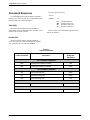
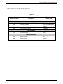
Technical Specifications for 3800 Series Modems . . . . . . . . . . . . . . . . . . . . . . . . . .
EIA-232-D Pin Assignments . . . . . . . . . . . . . . . . . . . . . . . . . . . . . . . . . . . . . . . . . . .
EIA RS-366-A Pin Assignments . . . . . . . . . . . . . . . . . . . . . . . . . . . . . . . . . . . . . . . .
VF Connector Pin Assignments: Models 3810 and 3820 . . . . . . . . . . . . . . . . . . . . .
VF Connector Pin Assignments: TELCO Jacks . . . . . . . . . . . . . . . . . . . . . . . . . . . .
V.25bis Commands . . . . . . . . . . . . . . . . . . . . . . . . . . . . . . . . . . . . . . . . . . . . . . . . . .
V.25bis Response Messages . . . . . . . . . . . . . . . . . . . . . . . . . . . . . . . . . . . . . . . . . . . .
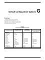
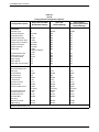
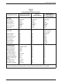
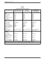
Factory Default Configuration Options . . . . . . . . . . . . . . . . . . . . . . . . . . . . . . . . . . .
November 1996
4-4
4-5
4-5
4-8
4-11
4-12
5-6
9-8
9-15
9-20
9-26
9-29
9-34
9-40
9-42
9-46
12-7
12-8
12-9
12-12
12-13
12-13
12-14
14-3
14-16
B-1
C-1
C-2
C-2
C-4
C-4
C-4
D-1
E-2
E-3
E-5
E-5
F-4
F-5
G-1
v
Preface
Objectives and Reader
Assumptions
Appendix C provides instructions for performing
diagnostic tests when data communications problems
occur.
This manual describes how to install and operate the
COMSPHEREr 3800 Series standalone and
carrier-mounted modems. It is assumed that you have a
basic understanding of modems and their operation.
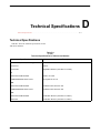
Appendix D provides technical specifications.
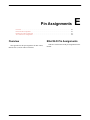
Appendix E provides EIA RS-232, EIA RS-366A, and
VF TELCO pin assignments.
Appendix F provides V.25bis dialing information.
How to Use This Manual
Chapter 1 provides information about the 3800 Series
modems’ features.
Appendix G provides a list of all default configuration
options available for the four factory preset
configurations: Async Dial, Sync Dial, Sync Leased, and
UNIX Dial.
Appendix H provides an equipment list for 3800 Series
modems.
Chapter 2 and Chapter 3 provide instructions for
installing the 3800 Series modems.
Chapter 4 provides the information required to operate
the Model 3810 and Model 3820 using the diagnostic
control panel (DCP) and the Model 3811 using the
COMSPHERE 3000 Series Carrier’s shared diagnostic
control panel (SDCP).
Chapters 5 through 12 describe the eight branches of
the front panel command sets: Call Setup, Talk/ Data,
Status, Test, Configure, Control, Remote, and Security.
Chapter 13 provides an overview of fax modem
operation.
Chapter 14 provides instructions for displaying and
changing AT commands and S-registers.
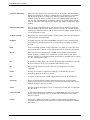
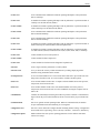
The Glossary provides a description of terms used
throughout this manual.
A reference card is inserted inside the back cover.
Related Documents
3000-A2-GA31
COMSPHERE 3000 Series
Carrier, Installation Manual
6700-A2-GY31
COMSPHERE 6700 Series
Network Management System
User’s Guide
3610-A2-GZ45
3600 Hubbing Device
Feature Number 3600-F3-300
Installation Instructions
Appendix A provides a menu tree for 3800 Series
modems.
Appendix B provides a list of the result codes produced
by 3800 Series modems.
3810-A2-GB30-20
Call your sales representative to order additional
product documentation.
November 1996
vii
Introduction
Overview . . . . . . . . . . . . . . . . . . . . . . . . . . . . . . . . . . . . . . . . . . . . . . . . . . . . . . . . . . . . . . . . . . . . . . . . . .
Features . . . . . . . . . . . . . . . . . . . . . . . . . . . . . . . . . . . . . . . . . . . . . . . . . . . . . . . . . . . . . . . . . . . . . . . . . . .
Options . . . . . . . . . . . . . . . . . . . . . . . . . . . . . . . . . . . . . . . . . . . . . . . . . . . . . . . . . . . . . . . . . . . . . . . . . . .
COMSPHERE 3800 Series Models . . . . . . . . . . . . . . . . . . . . . . . . . . . . . . . . . . . . . . . . . . . . . . . . . . . . .
Overview
The COMSPHERE 3800 Series modems, a new
generation of full-feature, high-speed dial modems, offer
reliable asynchronous and synchronous operation over
dial- or leased-lines networks. The 3800 Series modems’
unique software defineability allows for the addition of
future enhancements, whether it is installing new features
or firmware upgrades.
Through its downloading capability, any 3800 Series
modem can be upgraded to the latest firmware, requiring
no new hardware investment or on-site personnel, and
little or no downtime. These modems support a wide
range of modulation schemes and offer control using
either AT commands, the user-friendly diagnostic control
panel (DCP) or the optional COMSPHERE 6700 Series
Network Management System (NMS). The NMS
performs extensive monitoring, testing, reporting, and
restoral functions to assist in managing your network.
High-speed data transfer and reliable throughput at
data rates as high as 19,200 bps (V.32terbo) over dial lines
is guaranteed by employing the latest techniques in
CCITT V.42bis/MNP Class 5 data compression and
CCITT V.42/MNP error correction. In addition to fast line
speeds, the modem can send data to the DTE at speeds as
high as 115,200 bps.
3810-A2-GB30-20
1
1-1
1-2
1-2
1-2
The 3800 Series modem is extremely versatile when
used in modem pooling environments; it allows multiple
users to temporarily customize settings in the 3800 Series
modem, thereby permitting communication with the
calling modem. Upon disconnection, the 3800 Series
modem falls back to its original configuration settings and
resumes normal operation.
The modem’s compatibility with a number of dialing
methods and protocols, such as asynchronous AT
commands, CCITT V.25bis dialing, EIA RS-366-A
dialing for carrier-mounted modems, and the user-friendly
diagnostic control panel (DCP), permits the 3800 Series
modem to be used in a variety of applications and
environments while also allowing control over modem
configuration, dialing, and diagnostics. The 3800 Series
modems offer four preset factory configurations
containing the most often used modem settings. These
factory presets provide quick configuration for any
asynchronous/ synchronous dial, synchronous leased, or
UNIXr hardware-based dial environments.
The 3800 Series family is available in three models:
the Model 3810, a 4-wire/2-wire standalone modem; the
Model 3811, a carrier- mounted version of the standalone
unit; and the Model 3820, a 2-wire standalone unit. All
three models offer a variety of modulation schemes and
network enhancements while still providing reliable,
high-speed data transmission using the latest in modem
technology.
November 1996
1-1
COMSPHERE 3800 Series Modems
• High-speed transmission using asynchronous,
synchronous, or UNIX devices over full- or
half-duplex dial networks or 2-wire/4-wire leased
lines.
Features
The 3800 Series modems have a wide variety of
features.
• Dial-Line Modulations: V.32terbo (19,200 and
16,800 bps), CCITT V.32bis (14,400, 12,000, 9600,
7200, and 4800 bps), V.32 (9600 and 4800 bps),
V.22bis (2400 bps), V.22 (1200 bps), V.21
(300 bps), Bell 212A, (1200 bps), and Bell 103J
(300 bps).
• Two-wire/four-wire Leased-Line Modulations:
V.32terbo (19,200 and 16,800 bps), V.32bis
(14,400, 12,000, 9600, 7200, and 4800 bps),
V.32 (9600 and 4800 bps), V.22bis (2400 bps).
• Four factory-defined configurations and two
user-defined configuration areas.
• Availability in either the 2-wire/4-wire standalone
and carrier mount, or the 2-wire only standalone
models.
• Originate Security and three Answer Security
modes.
• Convenient migration to new or optional features
through software downloading.
• Directory #1 Callback capability.
• CCITT V.42bis and MNP Class 5 data compression.
• Dial Access Security which guards against
unwanted user access to the host DTE.
• Virtual error free data integrity with CCITT V.42
and MNP Level 4 error control.
• Hayes Autosync support.
• Automatic and manual single call dial backup and
dial standby capabilities for 4-wire leased-line
applications (Model 3810 and Model 3811).
• Diagnostic, control, monitor, and call statistic
capabilities through the COMSPHERE 6700 Series
NMS.
• Dial-line data rates from 300 bps–19,200 bps.
Leased-line rates from 2400 bps–19,200 bps.
• Class 2 Fax modulations: CCITT V.17 (14,400,
12,000, 9600, 7200 bps), V.29 (9600, 7200 bps) and
V.27ter (4800, 2400 bps).
• Asynchronous dial DTE data rates from
300 bps–115,200 bps.
• A diagnostic control panel (DCP) on the front bezel
that displays the connect status, data rate, type of
error control or compression, test results, alarm
status of DTE or VF parameters for both local and
remote modems.
• Storage of up to 10 telephone numbers to directory
locations.
• Compatibility with the industry de facto standard
AT Command set.
• Dialing via DCP, AT commands, CCITT V.25bis
commands, or RS-366-A (Model 3811 only).
• Configuration of software options via the
AT Command set or DCP.
Options
The 3800 Series modems also may have the following
optional features:
• A unique Paradyne modem pooling feature that
preserves the answering modem’s permanent
configuration, but allows multiple users to
temporarily adapt parameters for individual
requirements.
1-2
• Complement of self-tests, local and remote
loopbacks including CCITT compatible V.54.
COMSPHERE 3800 Series
Models
The COMSPHERE 3800 Series modem is available in
several models.
• Model 3810, a 4-wire/2-wire standalone unit
capable of operation on 2-wire dial, or 4-wire
leased or 2-wire leased lines.
• Model 3811, a 4-wire/2-wire carrier-mounted
modem for installation into a COMSPHERE
3000 Series Carrier; it is capable of operation on
dial, or 4-wire leased or 2-wire leased lines.
• Model 3820, a 2-wire standalone unit capable of
operation on dial or 2-wire leased lines.
November 1996
3810-A2-GB30-20
Model 3810 and 3820 Installation
Overview . . . . . . . . . . . . . . . . . . . . . . . . . . . . . . . . . . . . . . . . . . . . . . . . . . . . . . . . . . . . . . . . . . . . . . . . .
3800 Series Modem Package . . . . . . . . . . . . . . . . . . . . . . . . . . . . . . . . . . . . . . . . . . . . . . . . . . . . . . . . . .
Customer-Supplied Equipment . . . . . . . . . . . . . . . . . . . . . . . . . . . . . . . . . . . . . . . . . . . . . . . . . . . . . .
Model 3810 or Model 3820 Modem Installation . . . . . . . . . . . . . . . . . . . . . . . . . . . . . . . . . . . . . . . . . . .
Connecting Model 3810 and Model 3820 Modems with Supplied Cables . . . . . . . . . . . . . . . . . . . . .
DTE Connection . . . . . . . . . . . . . . . . . . . . . . . . . . . . . . . . . . . . . . . . . . . . . . . . . . . . . . . . . . . . . . . . . . . .
Dial Network Connection . . . . . . . . . . . . . . . . . . . . . . . . . . . . . . . . . . . . . . . . . . . . . . . . . . . . . . . . . . . . .
Model 3810 Dial-Line Connection . . . . . . . . . . . . . . . . . . . . . . . . . . . . . . . . . . . . . . . . . . . . . . . . . . . . . .
Model 3820 Dial-Line Connection . . . . . . . . . . . . . . . . . . . . . . . . . . . . . . . . . . . . . . . . . . . . . . . . . . . . . .
Model 3810 4-Wire/2-Wire Leased-Line Connection . . . . . . . . . . . . . . . . . . . . . . . . . . . . . . . . . . . . . . .
Model 3820 2-Wire Leased-Line Connection . . . . . . . . . . . . . . . . . . . . . . . . . . . . . . . . . . . . . . . . . . . . . .
Model 3810 and Model 3820 Telephone Connection . . . . . . . . . . . . . . . . . . . . . . . . . . . . . . . . . . . . . . . .
Dial Network Management System Connection . . . . . . . . . . . . . . . . . . . . . . . . . . . . . . . . . . . . . . . . . . . .
AC Power Transformer Connection . . . . . . . . . . . . . . . . . . . . . . . . . . . . . . . . . . . . . . . . . . . . . . . . . . . . .
Modem Power-Up . . . . . . . . . . . . . . . . . . . . . . . . . . . . . . . . . . . . . . . . . . . . . . . . . . . . . . . . . . . . . . . . . . .
Removing and Replacing Model 3810 and Model 3820 Modems . . . . . . . . . . . . . . . . . . . . . . . . . . . . . .
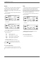
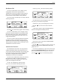
Overview
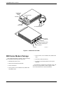
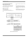
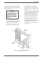
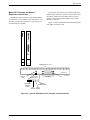
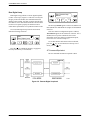
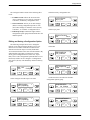
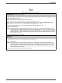
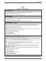
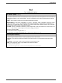
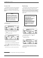
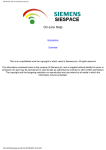
The standalone Model 3810 modem (Figure 2-1) is
capable of either dial or 4-wire/2-wire leased-line
operation. The modem is controlled using either AT
commands or the diagnostic control panel (DCP). The
DCP consists of an LCD which displays the Top-Level
menu, three function keys and four directional keys which
allow you to maneuver and choose DCP selections, and a
row of 12 LED status indicators which display modem
activity. For a better understanding of DCP operation,
refer to Chapter 4, DCP Operation.
The rear of the modem contains an ON/Off power
switch, a low voltage ac power connector, an 8-pin
modular connector for phone or leased-line connection, an
3810-A2-GB30-20
2
2-1
2-2
2-3
2-3
2-4
2-4
2-6
2-6
2-6
2-7
2-7
2-7
2-7
2-7
2-8
2-8
8-pin modular connector for dial-line connection, a 4-pin
modular connector for network management, and a
DB-25-S DTE connector.
The standalone Model 3820 is capable of dial and
2-wire leased-line operation. Its DCP functions are similar
to the Model 3810 except it has only six LED status
indicators. For more information regarding the DCP, refer
to Chapter 4, DCP Operation.
The rear of the modem contains an ON/Off power
switch, a low voltage ac power connector, an 8-pin
modular connector for external telephone use, an 8-pin
modular connector for dial-line or 2-wire leased-line
connection, a 4-pin modular connector for network
management, and a DB-25-S DTE connector.
November 1996
2-1
COMSPHERE 3800 Series Modems
DIAGNOSTIC
CONTROL
PANEL
LCD AND KEYPAD
SPEAKER
STATUS
INDICATORS
AC TRANSFORMER
EIA-232-D
INTERFACE
NMS
DIAL/LEASED (3820)
PHONE/LEASED (3810)
AC POWER IN
ON/OFF
496-13096-02
Figure 2-1. Model 3810 and 3820
3800 Series Modem Package
• One 8-position, 8-wire modular cord (Model 3810
only)
After opening the modem’s package, check for damage
and verify that the following items are present:
• One ferrite choke and cable tie
• Fax software and documentation (if fax option
installed)
• Manual and reference card
• Model 3810 or Model 3820 modem
• Power transformer
• One 6-position, 4-wire modular cord (Model 3810
and Model 3820)
2-2
If any hardware components are damaged, notify your
sales or service representative. Refer to page A in the
front of this document for contact information.
November 1996
3810-A2-GB30-20
Model 3810 and 3820 Installation
Customer-Supplied Equipment
The following customer-supplied equipment is
required to complete a data communications system using
either the Model 3810 or Model 3820 modem:
• A DTE with an available EIA-232-D serial port.
• A standard EIA-232-D male-to-female cable with a
male DB-25-S connector at one end to attach to the
modem.
• One of the following modular dial or leased
network interfaces:
If the modem is to be managed by a network
management system, a Shared Diagnostic Unit (SDU)
must be supplied and properly connected to the network
management controller. For proper network management
connection to the SDU, refer to the COMSPHERE
6700 Series Network Management System User’s Guide.
For installation of the 3000 Series Carrier into a
cabinet, refer to the COMSPHERE 3000 Series Carrier,
Installation Manual.
Model 3810 or Model 3820
Modem Installation
— RJ45S for dial programmable applications
— RJ11C for dial permissive applications
— An 8-position to 6-position crossover cable for
JM8 leased-line applications only
The following customer-supplied equipment is
required for the installation of a Model 3811 modem:
• A COMSPHERE 3000 Series Carrier.
• A male-to-female 50-pin mass termination cable.
One Network Interface Module (NIM) for modems
installed in Slots 1–8 and one NIM for modems
installed in Slots 9–16 (required for dial-line
applications).
Before installing your standalone modem, make sure
your installation site is clean and well-ventilated. Allow
space around the modem for installing cables and
telephone cords, and make sure the modem is located
within reach of the ac power outlet. The distance between
your modem and DTE should be minimized if DTE data
rates exceed 19,200 bps. Also, low capacitance cables
may be necessary for speeds greater than 19,200 bps or
distances greater than 50 feet.
The rear panel of both the Model 3810 and Model 3820
modems have the following switches and connectors (see
Figures 2-2 and 2-3 which appear later in this chapter):
• An ON/Off power switch.
• One of the following modular or 50-pin dial or
leased network interfaces:
• A 5-pin DIN type power receptacle for ac power
transformer.
— RJ11C for single line dial permissive
applications
• An 8-pin modular keyed jack for 4-wire/2-wire
leased lines or external telephone set on the
Model 3810. On the Model 3820, this jack is for
external telephone set use only.
— RJ45S for single line dial programmable
applications
— RJ21X for multiple line dial permissive
applications
— RJ27X for multiple line programmable
applications
• An 8-pin modular keyed jack for dial (Public
Switched Telephone Network, or PSTN) lines on
the Model 3810. On the Model 3820, this jack is for
dial or 2-wire leased lines.
— 66 punchdown block or other demarcation
device
• A 4-pin modular jack for Network Management
System (NMS) connection for future release.
• One 6-position to 6-position modular cord (required
for network management applications).
• A 25-pin DB-25-S receptacle for DTE interface.
• A Shared Diagnostic Unit (SDU) (required for
network management applications).
3810-A2-GB30-20
November 1996
2-3
COMSPHERE 3800 Series Modems
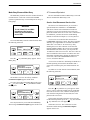
Connecting Model 3810 and Model 3820
Modems with Supplied Cables
1. Make sure the modem’s rear panel power switch is
Off.
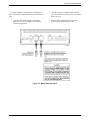
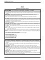
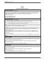
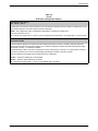
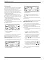
Figure 2-2 and Figure 2-3 show how Model 3810 and
Model 3820 modems are connected to certain TELCO
jack types using the supplied cables. For other TELCO
connections, refer to Appendix E.
2. Connect the DB-25-P (male) connector on the
cable to the DB-25-S (female) connector labeled
DTE (Figures 2-2 and 2-3) on the modem’s rear
panel. Use a small screwdriver to tighten the cable
to the modem.
DTE Connection
3. Connect the DB-25-P connector on the cable to
the DB-25-S connector on the DTE. Use a small
screwdriver to tighten the cable to the DTE.
Use the following procedures to connect the
EIA-232-D cable and ferrite choke from the modem to the
DTE:
Figure 2-2. Model 3810 Rear Panel
2-4
November 1996
3810-A2-GB30-20
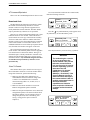
Model 3810 and 3820 Installation
To ensure compliance with FCC Part 15 Regulations, a
ferrite choke must be installed on the EIA-232-D interface
cable.
1. Open the ferrite choke and place it around the
DTE cable as close as possible to the connector
attached to the modem.
2. Close the two halves around the cable and snap
the ferrite choke shut, pressing down on the plastic
latch to secure it.
3. Install a cable tie behind the ferrite choke to
prevent it from sliding along the cable.
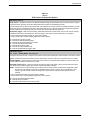
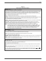
Figure 2-3. Model 3820 Rear Panel
3810-A2-GB30-20
November 1996
2-5
COMSPHERE 3800 Series Modems
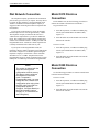
Dial Network Connection
The telephone company provides the line termination
jacks for the type of service you request. You may choose
to operate in either Permissive or Programmable mode.
Advance coordination with the telephone company is
suggested when connecting the modem to telephone dial
lines (PSTN).
If you operate in the Permissive mode, the modem’s
transmit output level is fixed at approximately –9 dBm.
The telephone company assumes that the line loss is
3 dBm and no compensation is provided for additional
losses. The resulting level at the telephone central office
could be lower than the nominal –12 dBm provided with
Programmable mode. A Permissive mode telephone line
is usually terminated with a USOC RJ11C jack.
Model 3810 Dial-Line
Connection
For the Model 3810, use the following procedures to
connect the modem to the dial network interface:
Programmable mode
1. Insert the 8-position, 8-conductor modular plug
into the jack labeled DIAL/ LEASED (3820),
Figure 2-2.
2. Insert the other end of the modular cord into the
dial network interface.
Permissive mode
If you operate in the Programmable mode, the
telephone company installs a program resistor that adjusts
the modem’s output level so that the signal entering the
telephone company’s central office is at the maximum
allowable level of –12 dBm. Telephone lines for the
Programmable mode are usually terminated with a USOC
RJ45S jack or an RJ41S jack switched to Programmable.
NOTE
The modem is shipped with the
Async Dial factory preset
configuration stored in memory.
This factory preset configures
the modem for Permissive
mode. To operate in
Programmable mode, you must
change the Dial Transmit Level
configuration option using either
the DCP (refer to the Dial Line
configuration options in
Chapter 9, Configure Branch) or
the AT&J command (refer to
Chapter 14, AT Command Set
and S-Registers).
2-6
1. Insert the 6-position, 4-conductor modular plug
into the jack labeled DIAL/ LEASED (3820),
Figure 2-2.
2. Insert the other end of the modular cord into the
dial network interface.
Model 3820 Dial-Line
Connection
Use the following procedures to connect a Model 3820
to the dial network interface:
Permissive mode
1. Insert the 6-position, 4-conductor modular plug
into the jack labeled DIAL/ LEASED (3820),
Figure 2-3.
2. Insert the other end of the modular cord into the
dial network interface.
November 1996
3810-A2-GB30-20
Model 3810 and 3820 Installation
Model 3810 4-Wire/2-Wire
Leased-Line Connection
Dial Network Management
System Connection
Use the following procedures to connect a Model 3810
to the leased-line network interface:
For Model 3810 and 3820 modems, use the following
procedures to connect the modem to the network
management system interface:
1. Insert the 8-position, 8-conductor modular plug
into the jack labeled PHONE/ LEASED (3810),
Figure 2-2.
1. Insert the subminiature 4-conductor modular plug
of the 3600 Hubbing Device into the jack labeled
NMS (Figure 2-2 or 2-3).
2. Insert the other end of the modular cord into the
leased-line network interface.
3. If the Model 3810 has a dial backup line, follow
the steps listed in Model 3810 Dial-Line
Connection section.
Model 3820 2-Wire
Leased-Line Connection
Use the following procedures to connect a Model 3820
modem to the 6-pin, center pair, leased-line network
interface. For 2-wire leased line connection to a JM8
network interface, refer to Figure E-1 in Appendix E:
2. Connect the 3600 Hubbing Device to the network
management system.
Refer to the 3600 Hubbing Device Feature Number
3600-F3-300 Installation Instructions (3610-A2-GZ45)
for more information. Installation for the Model 3810 and
3820 modems is the same as for the 3610 DSU.
AC Power Transformer
Connection
Use the following procedures to connect the modem to
an ac power outlet:
1. Insert the 6-position, 4-conductor modular plug
into the jack labeled DIAL/LEASED (3820),
Figure 2-3.
2. Insert the other end of the modular cord into the
leased-line network interface.
1. Make sure the modem’s power switch is in the Off
position.
2. Insert the power transformer’s 5-pin DIN male
connector into the modem’s rear panel ac power
receptacle (Figures 2-2 and 2-3).
3. Insert the power transformer into a grounded ac
power outlet.
Model 3810 and Model 3820
Telephone Connection
Use the following procedures to connect the modem to
a telephone:
1. Insert the 6-position, 4-conductor modular plug
into the jack labeled PHONE/LEASED (3810).
2. Insert the other end of the modular cord into the
telephone.
3810-A2-GB30-20
November 1996
2-7
COMSPHERE 3800 Series Modems
Modem Power-Up
Once your modem is properly connected to the DTE,
dial and/or leased lines, and ac outlet, press the modem’s
rear panel power switch to the ON position. The modem
begins a power-up self-test. This test takes several
seconds to perform, and verifies the operation of most
hardware components within the modem. If successful,
the LCD displays Power On Selftst Passed and continues
to the Top-Level menu screen.
Removing and Replacing
Model 3810 and
Model 3820 Modems
To remove and replace a Model 3810 or Model 3820
modem, perform the following steps:
Power On Selftst
Passed
F1
F2
1. Make sure the modem is offline, and press the
modem’s rear panel power switch to the Off
position.
2. Disconnect the power cord from the ac power
outlet, and then from the connector on the rear of
the modem.
F3
3. Disconnect the dial and leased-line modular cords
from the modem’s rear panel.
If a failure occurs during the self-test, the LCD
displays Power On Selftst Failed for several seconds.
The LCD then displays the Top-Level menu screen with
the message Power on Fail appearing on the top line of
the LCD. Although a failure has occurred, the modem will
attempt to operate. This allows you to activate a more
thorough self-test using the Test branch. Refer to
Chapter 8, Test Branch.
2-8
November 1996
4. Disconnect the DTE interface cable from the
modem’s rear panel.
If the modem is to be removed for service, return
it using the procedures on page A in the front of
this document for contact information.
5. Install the replacement modem as described in the
Model 3810 or Model 3820 Modem Installation
section of this chapter, and configure it the same
way as the modem being replaced.
3810-A2-GB30-20
Model 3811 Installation
3
Overview . . . . . . . . . . . . . . . . . . . . . . . . . . . . . . . . . . . . . . . . . . . . . . . . . . . . . . . . . . . . . . . . . . . . . . . . . . 3-1
Model 3811 Installation . . . . . . . . . . . . . . . . . . . . . . . . . . . . . . . . . . . . . . . . . . . . . . . . . . . . . . . . . . . . . . 3-2
Removing and Replacing Model 3811 Modems . . . . . . . . . . . . . . . . . . . . . . . . . . . . . . . . . . . . . . . . . . . . 3-4
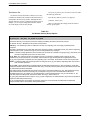
Overview
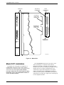
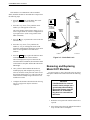
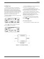
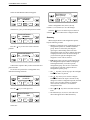
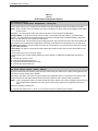
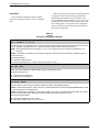
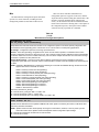
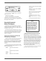
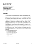
The carrier-mounted Model 3811 modem (Figure 3-1)
is capable of dial or 4-wire/2-wire leased-line operation
and installs into a COMSPHERE 3000 Series Carrier. The
Model 3811’s faceplate has 16 LED status indicators for
displaying modem activity and an audio speaker jack for
the carrier’s optional speaker.
The Model 3811 modem’s rear has two DTE edge card
connectors that mount into a connector plate located on
the rear of the carrier. This connector plate has two
DB-25-S connectors, one providing an EIA RS-232 DTE
interface and one providing an EIA RS-366A DTE
interface. The Model 3811 derives ac power from the
COMSPHERE 3000 Series Carrier’s backplane which is a
common bus to all devices installed in the carrier. The
user interface to any Model 3811 is through the shared
diagnostic control panel (SDCP), an optional feature
3810-A2-GB30-20
similar to the DCPs on the Model 3810 and Model 3820.
For a better understanding of DCP operation, refer to
Chapter 4, DCP Operation.
The COMSPHERE 3000 Series Carrier has a total of
17 slots. The first slot, Slot 0, is reserved for the Shared
Diagnostic Unit (SDU) while the remaining 16 slots can
house up to 16 Model 3811 modems, or for mixed
networks, a combination of Model 3811 modems and
Model 3611 Data Service Units (DSUs). An SDU is a
circuit card that provides SDCP and network management
interfaces to modems and DSUs installed in the carrier.
SDUs are only required if a single SDCP is used by
multiple COMSPHERE 3000 Series Carriers in a cabinet
or if a network management system (NMS) is used.
For more details on the COMSPHERE 3000 Series
Carrier, refer to the COMSPHERE 3000 Series Carrier,
Installation Manual.
November 1996
3-1
COMSPHERE 3800 Series Modems
EIA-232/V.24
CONNECTOR
FACEPLATE
Status
EIA-232/V.24
EDGE CARD
CONNECTOR
Pwr
EIA232/V.24
Alrm
142
Test
Dial
125
REAR
CONNECTOR
PLATE
RI
Busy
103
TXD
104
RXD
105
RTS
106
CTS
107
DSR
108
DTR
109
LSD
RS-366A/V.25
EDGE CARD
CONNECTOR
Front Panel
V.35 (3600/3500)
SQ
RS366A/V.25 (3800)
Serv
RS-366A/V.25
CONNECTOR
Spkr
3811
496-13155-02
Figure 3-1. Model 3811
Model 3811 Installation
The Model 3811 is designed for installation in a
COMSPHERE 3000 Series Carrier which supplies
operating power and the dial and/or leased-line network
connections. For correct power, DTE, dial-line,
leased-line, NIM, and network management cabling
information, refer to the COMSPHERE 3000 Series
Carrier, Installation Manual.
3-2
The COMSPHERE 3000 Series Carrier has 17 slots
which can hold up to 16 modems and one Shared
Diagnostic Unit (SDU). The SDU is required when the
modems in the carrier are controlled by an NMS, or when
multiple carriers in a cabinet configuration are to be
controlled by a single shared diagnostic control panel
(SDCP). The SDCP of the COMSPHERE 3000 Series
Carrier is the user interface to the Model 3811 modem. A
single SDCP can control up to eight carriers containing up
to 128 compatible modems.
November 1996
3810-A2-GB30-20
Model 3811 Installation
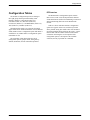
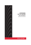
The installation of a Model 3811 varies slightly if an
SDCP is installed on the front of the carrier. To install a
Model 3811 modem into the carrier without an SDCP,
perform the following steps:
2. At the front of the carrier, hold the modem
vertically, with the latch on its faceplate in the
open position, and insert it into the top and bottom
card guides of one of the slots numbered 1–16 (see
Figure 3-2).
Slide the modem into the slot, aligning the modem
with the rear connector plate, until the backplane
connector and DTE connector seat firmly into the
back of the carrier. The faceplate latch
automatically closes as you push the modem into
the carrier. To lock the modem into the carrier,
press the faceplate latch until a click is heard.
CAUTION
If the Model 3811 is removed
from the carrier, always use a
ground strap when handling
the modem. Always store the
Model 3811 in an antistatic
bag when it is removed from
the carrier.
1. At the rear of the carrier install the rear connector
plate. Make sure the plate uses the same slot
position as that intended for the modem.
Loosely fasten the plate. This allows for slight
adjustments later when installing the modem.
3. If the carrier is ON, the Power LED on the
faceplate of the 3811 lights. After several seconds
the modem completes its power-up self-test in
which all faceplate LEDs light. If the modem fails,
the Alrm LED on the faceplate flashes.
Return to the rear of the carrier and tighten the
rear connector plate.
Figure 3-2. Installing a Model 3811 Modem
3810-A2-GB30-20
November 1996
3-3
COMSPHERE 3800 Series Modems
If the modem is to communicate with an installed
SDCP, install the modem as described above and perform
the following steps:
CIRCUIT
CARD
GUIDE
1. Press the Select key on the SDCP. The cursor
appears in the carrier selection entry.
2. Press the F1 (") or F2 (↓) key until the carrier
number you want appears on the LCD.
CLOSED
(LOCKED)
The carrier number selection has a range of 1 to 8
since a single SDCP can control a configuration of
up to eight carriers. (This is only possible if the
SDU is installed.)
3. Press the
key to position the cursor on the slot
selection entry.
CIRCUIT
PACK
LOCK
CIRCUIT
CARD
GUIDE
OPEN
(UNLOCKED)
4. Press the F1 (") or F2 (↓) key until the slot
number (1–16) you want appears on the LCD.
Ignore the AB designator that appears on the LCD
since it is not applicable to the 3800 Series
modems.
LATCH
5. Press the Select key to place the SDCP in direct
communication with the selected modem.
The LCD displays the Top-Level menu for the
selected modem. In addition, the Front Panel LED
on the modem’s faceplate and the OK LED on the
SDCP light.
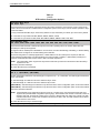
6. Once you have determined that the modem is
installed properly and completed its power-up
self-test, rotate the circuit pack lock until it covers
the faceplate latch (Figure 3-3). This prevents the
modem from accidently being removed once it is
installed in a carrier.
495-11985a-03
Figure 3-3. Circuit Pack Lock
Removing and Replacing
Model 3811 Modems
It is not necessary to power down the carrier to remove
and replace a Model 3811 modem. Perform the following
steps:
7. Configure the modem as described in the Selecting
Factory Configuration Options section in
Chapter 4.
CAUTION
If the Model 3811 is removed
from the carrier, always use a
ground strap when handling
the modem. Always store the
Model 3811 in an antistatic
bag when it is removed from
the carrier.
1. Rotate the circuit pack lock until the release tab is
exposed.
2. Press down on the release tab and pull the modem
away from the carrier’s backplane.
3-4
November 1996
3810-A2-GB30-20
DCP Operation
Overview . . . . . . . . . . . . . . . . . . . . . . . . . . . . . . . . . . . . . . . . . . . . . . . . . . . . . . . . . . . . . . . . . . . . . . . . .
Diagnostic Control Panels . . . . . . . . . . . . . . . . . . . . . . . . . . . . . . . . . . . . . . . . . . . . . . . . . . . . . . . . . . . .
Models 3810 and 3820 Diagnostic Control Panels . . . . . . . . . . . . . . . . . . . . . . . . . . . . . . . . . . . . . . .
Model 3811 Faceplate and Shared Diagnostic Control Panel . . . . . . . . . . . . . . . . . . . . . . . . . . . . . . .
Status Indicators . . . . . . . . . . . . . . . . . . . . . . . . . . . . . . . . . . . . . . . . . . . . . . . . . . . . . . . . . . . . . . . . . . . .
Diagnostic Control Panel Operation . . . . . . . . . . . . . . . . . . . . . . . . . . . . . . . . . . . . . . . . . . . . . . . . . . . .
LCD Display . . . . . . . . . . . . . . . . . . . . . . . . . . . . . . . . . . . . . . . . . . . . . . . . . . . . . . . . . . . . . . . . . . . .
Hidden Choice Indicators . . . . . . . . . . . . . . . . . . . . . . . . . . . . . . . . . . . . . . . . . . . . . . . . . . . . . . .
Keypad . . . . . . . . . . . . . . . . . . . . . . . . . . . . . . . . . . . . . . . . . . . . . . . . . . . . . . . . . . . . . . . . . . . . . . . .
Menu Structure . . . . . . . . . . . . . . . . . . . . . . . . . . . . . . . . . . . . . . . . . . . . . . . . . . . . . . . . . . . . . . . . . . . .
Top-Level Menu Status and Operational Messages . . . . . . . . . . . . . . . . . . . . . . . . . . . . . . . . . . . . . .
Selecting Factory Configuration Options . . . . . . . . . . . . . . . . . . . . . . . . . . . . . . . . . . . . . . . . . . . . . . . . .
Using the Diagnostic Control Panel . . . . . . . . . . . . . . . . . . . . . . . . . . . . . . . . . . . . . . . . . . . . . . . . . .
Using AT Commands . . . . . . . . . . . . . . . . . . . . . . . . . . . . . . . . . . . . . . . . . . . . . . . . . . . . . . . . . . . . . .
Overview
4
4-1
4-1
4-1
4-3
4-4
4-6
4-6
4-6
4-6
4-7
4-8
4-13
4-13
4-13
The LCD displays the result of any command initiated
using the DCP. Most of these operations can be performed
from an attached asynchronous DTE using the
AT command set.
This chapter describes how to use the diagnostic
control panel (DCP) of the 3800 Series modem. It also
describes how to select and use each branch of the
Top-Level menu tree.
Models 3810 and 3820
Diagnostic Control Panels
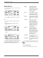
Diagnostic Control Panels
There are two types of DCPs: the front panel on the
standalone Model 3810 and Model 3820 modems, and the
shared diagnostic control panel (SDCP), an optional
feature used with a Model 3811 installed in a
COMSPHERE 3000 Series Carrier. Both DCPs have a
two-line, 32-character liquid crystal display (LCD) and
keypad through which Top-Level menu branches are
accessed to perform the following:
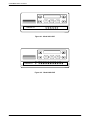
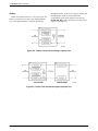
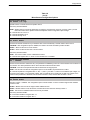
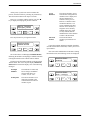
The DCPs of the Model 3810 and Model 3820 modems
(Figures 4-1 and 4-2) contain status indicators,
pushbutton-type keys, and an LCD.
• Initiate and disconnect dial operations
• Check modem status
• Set up configuration options
• Initiate diagnostic tests
• Access remote modems through the local modem’s
DCP
3810-A2-GB30-20
November 1996
4-1
COMSPHERE 3800 Series Modems
F1
F3
F2
RTS
CTS
TXD
LSD
RXD
105
106
103
109
104
SQ
COMSPHERE 3820
496-13068-02
Figure 4-1. Model 3810 DCP
F1
PWR
F3
F2
ALRM DIAG DTR
RTS
CTS
TXD
LSD
RXD
108
105
106
103
109
104
SQ
TEST RATE
COMSPHERE 3810
142
496-13067-02
Figure 4-2. Model 3820 DCP
4-2
November 1996
3810-A2-GB30-20
DCP Operation
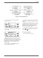
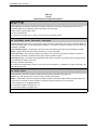
Model 3811 Faceplate and Shared
Diagnostic Control Panel
The faceplate of the Model 3811 contains LED status
indicators that monitor the operation of the modem. After
the SDCP is connected to the modem, the Front Panel
indicator of the selected modem lights to show that the
modem is connected.
The SDCP, is used to manage carrier-mounted Model
3811 modems. Use the SDCP to issue commands to, view
and select configuration options on, or monitor tests for a
specific Model 3811 modem.
Status
Status
Pwr
OK
Alrm
Alrm
Diag
In
Diag
Out
Figure 4-3 shows the SDCP and the Shared Diagnostic
Unit (SDU) it interfaces with.
142
Test
Dial
125
RI
Busy
Serv
SQ
103
TXD
104
RXD
105
RTS
106
CTS
107
DSR
108
DTR
109
LSD
Front Panel
Spkr
SDU
3811
CARRIER SLOTS 1–16
SDU
1
2
3
4
5
6
7
8
9
10
11
12
13
14
15
16
Select
OK
SELECT
KEY
Alarm BckUp Test
EC
STATUS
INDICATORS
OK
Alarm BckUp Test
NETWORK
DEVICE
ALARM
F1
F2
F3
KEYPAD
COMSPHERE 3000
LCD
496-13073-03
EC
ERROR
CORRECTION
DIAL
TEST
BACKUP MODE
Figure 4-3. Optional SDCP, Model 3811 Faceplate, and Optional SDU
3810-A2-GB30-20
November 1996
4-3
COMSPHERE 3800 Series Modems
Status Indicators
Model 3811’s faceplate, the SDCP, and the SDU faceplate
(Figure 4-3).
The 3800 Series modems’ status indicators
continuously provide information on the modem’s
operating condition. All of the status indicators on the
Model 3810 and Model 3820 appear on the DCP
(Figures 4-1 and 4-2), whereas the status indicators for the
carrier-mounted Model 3811 are located on the
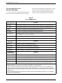
The standalone Model 3810 modem’s DCP has
12 LEDs, and the carrier-mounted Model 3811 has
16 LEDs. These LEDs are listed and described in
Table 4-1; LEDs specific to one model type have the
appropriate model number shown in the table.
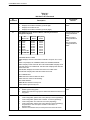
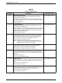
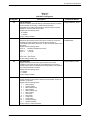
Table 4-1
Model 3810 and Model 3811 DCP LEDs
Label
Color
Indicates
Pwr
green
ON. Power is on and the modem is capable of operating.
Alrm
red
Flashing. A malfunction has been detected in either the modem or COMSPHERE
3000 Series Carrier.
Diag
(3810 only)
green
The modem has responded to a diagnostic command from network management.
DTR/108
green
The DTE has turned ON DTR or the modem has forced DTR ON.
Test/142
yellow
The modem is involved in a test. Normal operation is not possible.
Dial
(3811 only)
green
Flashing. The modem is attempting to establish a call over the dial network.
ON. The modem has established a dial connection.
OFF. A dial connection does not exist.
RI/125
(3811 only)
green
A ringing signal is being received.
Busy
(3811 only)
yellow
ON. The modem is placed in a forced busy condition and is off-hook.
Serv
(3811 only)
yellow
ON. The modem is connected to the carrier service line rather than the normally assigned
dial network.
SQ
yellow
The receive telephone line signal is degraded.
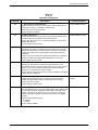
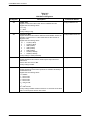
TXD/103
green
The modem is receiving data from the DTE to transmit. (ON equals space.)
RXD/104
green
Data is being transferred to the DTE. (ON equals space.)
RTS/105
green
RTS signal is ON.
CTS/106
green
CTS signal is ON.
LSD/109
green
The modem has detected a valid carrier signal and is capable of transferring data to the
DTE.
DSR/107
(3811 only)
green
DSR signal is ON.
Rate
(3810 only)
yellow
ON. The modem is connected at a data rate lower than the data rate it is configured for.
Front Panel
(3811 only)
yellow
4-4
OFF. The modem is connected at its configured data rate.
ON. The modem is connected to the carrier’s SDCP.
November 1996
3810-A2-GB30-20
DCP Operation
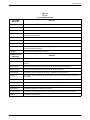
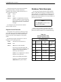
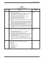
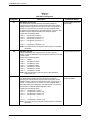
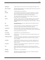
DCP LEDs for the standalone Model 3820 are listed
and described in Table 4-2.
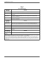
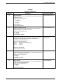
The SDCP LEDs are listed and described in Table 4-3.
Table 4-2
Model 3820 DCP LEDs
Label
Color
Indicates
RTS/105
green
RTS signal is ON.
CTS/106
green
CTS signal is ON.
TXD/103
green
The modem is receiving data from the DTE to transmit. (ON equals space.)
LSD/109
green
The modem receiver has detected a valid carrier signal and is capable of transferring data to
the DTE.
RXD/104
green
Data is being transferred to the DTE. (ON equals space.)
SQ
yellow
The receive telephone line signal is degraded.
Table 4-3
SDCP LEDs
Label
OK
Alrm
Color
green
red
Indicates
Power is ON and the modem is capable of operating.
The modem has detected a problem with its operation. For example, the modem failed a
self-test.
BckUp
yellow
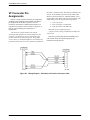
The modem, originally configured for leased-line operation, is now operating on dial
networks in a Dial Backup mode.
Test
yellow
The modem is involved in a test. Normal operation is not possible.
EC
green
Modem is in Error Control mode.
3810-A2-GB30-20
November 1996
4-5
COMSPHERE 3800 Series Modems
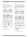
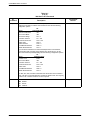
Hidden Choice Indicators
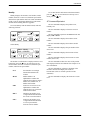
Diagnostic Control
Panel Operation
The 3800 Series modem’s diagnostic control panel
(DCP) is the user interface to all functions used to
configure and control the modem. This interface includes
the status light-emitting diodes (LEDs), and a two-line,
32-character liquid crystal display (LCD) and keypad
(Figure 4-4).
Use the DCP to display the following kinds of
information:
• DCP entry displays
Left Scroll Indicator <
• Remote modem access
HIDDEN
CHOICE
INDICATORS
RETURNS
DISPLAY TO
TOP-LEVEL
MENU
Idle:19.2
Call_Setup
F1
F2
The right scroll indicator displays when more choices
are available to the right of what is currently displayed
on the LCD.
The left/right scroll indicator displays when more
choices are available to the left and right of what is
currently displayed on the LCD.
• Configuration options
LCD
TOP
LINE
Right Scroll Indicator >
Left/Right Scroll Indicator
• Operational status
MOVES UP
ONE LEVEL
FROM CURRENT
DISPLAY
The Hidden Choice Indicators serve as an alert that
other selections are available besides what is currently
displayed on the LCD. These indicators appear as one of
the following symbols:
The left scroll indicator displays when more choices
are available to the left of what is currently displayed
on the LCD. The LCD does not wrap around to the first
choice once you have reached the end of choices.
Remote Mode Indicator
If the local 3800 Series modem establishes a
connection with the remote 3800 Series modem via the
Remote branch, then appears in place of the hidden
choice indicator on both modems.
F3
Keypad
LEFT
SCROLL
KEY
FUNCTION KEYS
LCD BOTTOM LINE
The DCP on the Model 3810 and Model 3820 has
seven keys while the optional SDCP of the COMSPHERE
3000 Series Carrier has eight keys. The additional key on
the carrier is the Select key, used to connect the SDCP
to a specific slot in the carrier.
RIGHT
SCROLL
KEY
Figure 4-4. 3800 Series LCD and Keypad
Key
The
key returns you to the Top-Level menu
display from anywhere in the menu tree.
LCD Display
The LCD consists of a top line and bottom line, with
each displaying a maximum of 16 characters at a time. If
additional information appears on the LCD than what is
currently displayed, a hidden choice indicator
(< >) appears in the upper right-hand corner of the
LCD. Use the
or
key to scroll in the indicated
direction to display more selections onto the LCD.
4-6
Pressing
while changing configuration options
displays the message Save Straps? Yes No. If No is
selected, changes made to configuration options are not
saved and the Top-Level menu appears. If Yes is selected,
then changes are saved to either Active (Saved),
Customer 1, or Customer 2 configuration areas.
November 1996
3810-A2-GB30-20
DCP Operation
Key
The
Talk/Data
Used to switch the modem
between Talk mode (the
modem is disconnected from
the VF line) and Data mode
(the modem is connected to
the VF line) when dialing via
either the DCP or the attached
telephone. (See Chapter 6.)
Status
Used to monitor the current
status of the VF line and DTE
interface as well as view the
identity of the modem. (See
Chapter 7.)
Test
Used to begin and end various
modem tests. (See Chapter 8.)
Configure
Used to change and save the
modem’s configuration
options. (See Chapter 9.)
Control
Used to control the modem’s
hardware and software
functions. (See Chapter 10.)
Remote
Used to access and control a
remote 3800 Series modem.
(See Chapter 11.)
Security
Used to control the modem’s
dial access security. Appears
only if the optional security
feature is installed. (See
Chapter 12.)
key moves you up one level in the menu tree.
and
Keys
Use the
and
keys to move the viewing
window left or right and to scroll the remaining
branches and selections into view. A maximum of
three selections can be displayed at one time.
These keys also allow you to move the cursor one
character to the left or right on data entry displays; for
example, to allow entry of one digit at a time.
F1, F2, F3 Keys
Function keys select the LCD choice that appears
above the function key; they are labeled F1, F2, and
F3. If a selection spans more than one function key,
then any of those keys choose that selection.
Select
Key (Model 3811 only)
The Select key appears on the optional SDCP of the
COMSPHERE 3000 Series Carrier. It is used to
connect the SDCP to a modem in a specific slot in the
carrier.
Menu Structure
The menu tree is a hierarchical structure used to
display functions that configure and control local and
remote 3800 Series modems. It is accessed via the DCP
and is shown in Appendix A.
The menu tree contains the following branches:
Call Setup
Menu tree branches are described in Chapters 5
through 12. Functions that appear on the LCD vary
depending upon the type of model installed, its operating
mode, and software configuration.
Used to dial, disconnect, and
answer telephone calls as well
as store up to 10 telephone
numbers in directory locations.
(See Chapter 5.)
“Status”
Call_Setup
Tlk/Data
Status
Test
Configure
Control
Remote
Security
494-13083-02
3810-A2-GB30-20
November 1996
4-7
COMSPHERE 3800 Series Modems
Top-Level Menu Status and
Operational Messages
Access to all menu tree branches from the DCP begins
at the Top-Level menu, the head of the menu hierarchy.
The LCD’s top line identifies the modem status, as listed
in Table 4-4, while the bottom line displays the main
menu tree branches and operational and dial access
security messages, as listed in Table 4-5 and Table 4-6.
Table 4-4
(1 of 3)
Top-Level Menu Status
Normal Operation
Status Message
Indicates
Fax Rx:MR*
Indicates that the modem is online, in fax receive modem, operating at the displayed data rate.
Fax Tx:MR*
Indicates that the modem is online, in fax transmit mode, operating at the displayed data rate.
Idle:MR*
The modem is configured for dial network operation and is on-hook.
Leased:MR*
The modem is operating on leased lines at the displayed data rate.
OnLine:MR* EC**
Indicates the modem is online, in Data mode, and operating at the displayed data rate. EC (error
control) displays if error control is operational.
Ring Indicate
The local modem is receiving an incoming ring.
Test:MR*
The modem is in test mode operating at the displayed data rate.
Alarm Status
Message***
Indicates
Make Busy
Indicates the modem is in a Make Busy condition.
Power On Fail
Indicates the modem has failed its Power-On Self-Test.
Self Health Fail
Indicates a failure in the modem’s hardware components.
Weak Battery
Indicates the battery is operating below 2 volts. Contact your sales or service representative.
Normal Call
Setup Messages
Indicates
Off Hook
The modem is off-hook and waiting to dial a telephone number.
Dialing
The remote modem is ringing.
Training
The modem is training or retraining.
EC Negotiating
The local and remote modems are negotiating the highest possible level of error control
compatible between both modems. Once a level is selected, this LCD message disappears.
* MR. Modem Rate indicates the data rate the modem is using. One of the following values appears: 300, 1200, 2400,
4800, 7200, 9600, 12K (12,000), 14.4 (14,400), 16.8 (16,800), or 19.2 (19,200) bps.
** EC. Error Control indicates the modem is online and using V.42 or MNP error control. One of the following values
appears after the modem rates listed above: MNP2, MNP3, MNP4, MNP5, V42, V42b, or NoEC. (NoEC indicates the
modem is connected in Buffer mode rather than error control. If an EC value does not appear, then the modem is in
Direct mode.)
*** The Alarm Status Messages only appear when the Normal Operation Status Messages display; the LCD alternates
between the two message sets.
4-8
November 1996
3810-A2-GB30-20
DCP Operation
Table 4-4
(2 of 3)
Top-Level Menu Status
Call Failure
Messages
Indicates
Busy Signal
The answering modem is busy.
Dial Line in Use
The modem is already operating on dial networks when another call attempt has been issued.
Invalid Number
The modem has dialed a telephone number not stored in a directory location.
No Answer Tone
The answering modem has not answered within the time limit specified by the No Answer
Timeout configuration option.
No Dial – DTR
The modem cannot dial because DTR is Off.
No Dial – Test
The modem cannot dial because it is running a Test.
No Dial Tone
The modem has aborted the call because it cannot detect a dial tone.
No Quiet Answer
The modem has detected No Quiet Answer (@) before the time-out setting of the No Answer
Disconnect configuration option.
Trunk Busy
The modem is receiving a fast (trunk) busy.
Call Disconnect
Messages
Indicates
ATH Disconnect
The modem has disconnected due to an ATH command.
Bad Lines Disc
The modem has disconnected because the lines do not support the modulation and/or data rate
selected.
No Carrier Disc
The modem disconnects due to the loss of carrier signal from the remote modem.
DTR Disconnect
The modem has disconnected due to the loss of DTR from the DTE.
EC Disconnect
The modem has disconnected due to failure to negotiate Error Control mode.
Inv Rate Disc
When using V.32bis modulation, the remote modem does not support the data rate used by the
local modem.
LnCurrnt Disc
The modem has disconnected due to the loss of line current.
LongSpace Disc
The modem has disconnected due to the detection of a long space.
NoData Disc
The modem has disconnected due to a lack of transmitted and received data.
Disconnecting
The modem has begun the disconnect sequence.
Rmt Cmnded Disc
The modem has disconnected due to a V.32 Cleardown received from the remote modem.
Talk Mode
The modem is in Talk mode.
3810-A2-GB30-20
November 1996
4-9
COMSPHERE 3800 Series Modems
Table 4-4
(3 of 3)
Top-Level Menu Status
Dial Backup
Messages
Indicates
Dial Standby
The modem is operating in Dial Standby mode.
DialBckUp:MR*
The modem is operating in a Dial Backup mode at the displayed data rate and is configured for
Direct mode.
Backup:MR* EC**
The modem is operating in Dial Backup mode and is configured for error control and data
compression on leased lines.
Stndby:MR* EC**
The modem is operating in Dial Standby mode and is configured for error control and data
compression on leased lines.
Firmware
Download Result
Messages
Indicates
DownldOnly Mode
Indicates that a local download of firmware or a remote cloning of firmware has failed. The
modem is currently in a Download Only mode in which only another download attempt is possible.
Frmware Upgrade
Indicates that a local download of firmware or a remote cloning of firmware was successful.
RemClone Failed
Displays on the local modem’s LCD and indicates that a remote cloning of firmware has failed.
Remote Clone OK
Displays on the local modem’s LCD and indicates that a remote cloning of firmware was
successful.
AT Command
Reset Message
Reset by AT
command
Indicates
The modem has performed a reset in response to an ATZ command.
* MR. Modem Rate indicates the data rate the modem is using. One of the following values appears: 300, 1200, 2400,
4800, 7200, 9600, 12K (12,000), 14.4 (14,400), 16.8 (16,800), or 19.2 (19,200) bps.
** EC. Error Control indicates the modem is online and using V.42 or MNP error control. One of the following values
appears after the modem rates listed above: MNP2, MNP3, MNP4, MNP5, V42, V42b, or NoEC. (NoEC indicates the
modem is connected in Buffer mode rather than error control. If an EC value does not appear, then the modem is in
Direct mode.)
4-10
November 1996
3810-A2-GB30-20
DCP Operation
Messages listed in Table 4-5 are common operational
messages that occur during modem operation. These
messages normally appear on the second line of the LCD.
Table 4-5
Common Operational Messages
Common
Operational
Messages
Indicates
Please Wait...
Appears when a command to a local device takes more than two seconds to complete.
Command Sent...
Appears when a command is sent to a remote modem.
No Rem Response or
Remote Modem Fail
Appears when a remote modem does not respond to a command within 5 seconds.
Command Complete
Appears when a command, issued to a local or remote modem, is completed.
Invalid Command
Appears when the modem cannot complete a command.
3810-A2-GB30-20
November 1996
4-11
COMSPHERE 3800 Series Modems
Messages listed in Table 4-6 are dial access security
messages that can occur when the optional security
feature is installed.
The Top-Level menu’s main branches appear on the
LCD in the order of Call Setup, Talk/ Data, Status, Test,
Configure, Control, Security, and Remote. These branches
are described in the following chapters.
Table 4-6
Dial Access Security Messages
Dial Access
Security
Messages
Indicates
Get VF PsWd
The answering modem is waiting for the originating caller to transmit a VF password.
Get DTE PsWd
The answering modem is waiting to receive a valid DTE password from the remote DTE.
VF PsWd Timeout
The modem did not finish answering a call (disconnected) because the allowed time limit was
exceeded before the modem received a VF password from the originating dialer.
Unknown DTEpswd
The modem did not finish answering a call (disconnected) because the DTE passwords received
from the remote DTE were invalid.
No Orig PsWd
The modem did not attempt to establish a call as requested because the AT dial command did not
contain an originate access password.
Unknown VF PsWd
The modem did not finish answering a call (disconnected) because the modem received an
invalid VF password.
DTEpswd Timeout
The modem did not finish answering a call (disconnected) because the allowed time limit was
exceeded before the modem received a DTE password from the remote DTE.
Inval Orig PsWd
The modem did not attempt to establish the call as requested because the originate password in
the AT dial command was not valid.
DTR Dial Blocked
Appears if DTR dialing is used and Answer Access or Originate Access security is enabled. DTR
dialing is not permitted when security is enabled.
SecurityBlocked
Appears only when the modem is in base mode (a mode that occurs during a firmware download)
and Answer Access Security is enabled. In this case, the access verification capabilities are not
available and the modem does not pass data to the DTE under any circumstances.
4-12
November 1996
3810-A2-GB30-20
DCP Operation
Selecting Factory
Configuration Options
key until the appropriate factory
4. Press the
preset appears on the LCD, and press the
corresponding function key to select your choice.
After the modem passes the power-up self-test,
configure it for operation using one of the factory preset
configurations.
5. Choose Function appears and displays the Edit
and Save functions.
The 3800 Series modems have several factory preset
templates that contain the most commonly used
configuration options (straps) for Asynchronous Dial,
Synchronous Dial, Synchronous Leased (Answer or
Originate), UNIX hardware network, cellular mobile, and
cellular PSTN configurations. Your modem is shipped
from the factory with the Async Dial default configuration
options stored in memory. If Sync Dial, Sync Leased,
UNIX Dial, or Cellular is more appropriate for your
configuration, then you must change the factory setting
using either the modem’s DCP or the AT command set as
described in the following sections.
6. Press the F3 key (Save) to save the new factory
preset configuration to one of three configuration
areas, Active (Saved), Customer 1, or
Customer 2.
(These three configuration areas are nonvolatile
memory locations. Active (Saved) contains the
most recently saved changes to any configuration
options. In the event of power loss, the modem
retrieves these configuration options. Customer 1
and Customer 2 are user-defined configuration
areas.)
The LCD now displays Sav EditArea to.
The preset configuration gives you a “head start” in
getting your modem operating and reduces the amount of
time required to configure your modem. For a better
understanding of DCP operation and factory preset
configuration options, refer to Chapter 9, Configure
Branch.
key until the appropriate
7. Press the
configuration area appears on the LCD, then press
the corresponding function key to select your
choice. (Saving configuration options to the
Active (Saved) configuration area automatically
saves them to the Active (Operating)
configuration area.) The LCD displays Command
Complete.
Using the Diagnostic Control Panel (DCP)
The DCP’s liquid crystal display (LCD) consists of two
16-character lines which display modem status, control
functions, and configuration options as well as indicating
your location in the Top-Level menu tree (Appendix A).
To change the factory template using the DCP, perform
the following steps:
1. On the DCP press the
comes into view.
8. The modem is now configured with the selected
key to return to the
factory template. Press the
Top-Level menu.
Refer to Chapter 9, Configure Branch, for more
information regarding default factory configuration
options.
key until Configure
Using AT Commands
2. Press the function key below Configure to select
the Configure branch.
The LCD now displays Ld EditArea frm.
key until Factory comes into view,
3. Press the
then press the F1 key to display the factory preset
configurations.
Factory preset configurations are Async Dial,
Sync Dial, Sync Leased, UNIX Dial, Cellular
(Mobile), and Cellular (PSTN). If Sync Leased is
selected, you must choose either Answer or
Originate mode.
3810-A2-GB30-20
When using AT commands, the following criteria must
be met:
• Make sure the asynchronous DTE’s communication
software is configured for 10-bit character format
(for example, 8 data bits, no parity, and 1 stop bit).
• Make sure the DTE (RS-232D) cable is attached to
the DTE connector on the rear of the Model 3810
or 3820 modem, or (for the Model 3811 modem)
the rear of the COMSPHERE 3000 Series Carrier,
and the correct serial communications port on the
asynchronous DTE.
November 1996
4-13
COMSPHERE 3800 Series Modems
• On initial power-up, the modem is in Command
mode. To verify that the modem is connected and
functioning properly, enter the following:
TYPE:
(NOTE: &F1, &F2, and &F4 remove AT
command control. The only way to return to AT
command control is through the DCP as described
earlier in Using the Diagnostic Control Panel
(DCP).)
AT
PRESS: Return (Enter)
and
The screen displays OK.
Where:
If the modem does not return OK, refer to Appendix C,
Troubleshooting.
(NOTE: These three configuration areas are
nonvolatile memory locations. Active (Saved)
contains the most recently saved changes to any
configuration options. In the event of power loss,
the modem retrieves these configuration options.
Customer 1 and Customer 2 are user-defined
configuration areas.)
NOTE
If you have already changed the
factory preset configuration you
may have lost AT command
control. To regain AT command
control, select, via the DCP, the
Async Dial factory preset
configuration as described
earlier in Using the Diagnostic
Control Panel (DCP).
PRESS: Return (Enter)
2. The selected factory configuration is saved.
To change a factory template using AT commands,
perform the following steps (for more information on
changing factory templates using AT commands, refer to
Chapter 14, AT Command Set and S-Registers).
1. Use the AT&F&W command to load the
appropriate factory configuration to the
appropriate storage area. Enter the following:
4-14
TYPE:
AT&Fy&Wn
Where:
y is one of the following Factory
configurations:
0 for Async Dial
1 for Sync Dial
2 for Sync Leased (Answer)
3 for UNIX Dial
4 for Sync Leased (Originate)
5 for Cellular (Mobile)
6 for Cellular (PSTN)
n is one of the following storage areas:
0 for Active (Saved)
1 for Customer 1
2 for Customer 2
The &V (View) command can be used to display the
configuration options in effect. The output of the &V
command can be saved to a file and printed (using your
communications software), providing both a record of
your configuration and a worksheet for configuration
enhancements. Refer to Chapter 14, AT Command Set and
S-Registers, for more on AT commands.
November 1996
3810-A2-GB30-20
DCP Operation
Diagnostic Control Panel
Security Access
To access the Front Panel (DCP) Security Access
function, perform the following:
NOTE
This page of the manual is
self-supporting and can be
removed to prevent unwanted
knowledge of the DCP security
access selections.
Press the
key three times.
Press the
key twice.
Press the
key once.
Frnt Panl Acces
Grant
Deny
F1
Use the DCP security access function to ‘‘lock” the
DCP of any 3800 Series modem and prevent unwanted
user access. Two options are available for this function:
Grant and Deny.
Grant allows any branch of the Top-Level menu to be
accessed from the DCP. Deny allows access only to the
Status branch of the Top-Level menu. All 3800 Series
modems are shipped from the factory with DCP access
granted.
3810-A2-GB30-20
F2
F3
Select Grant to allow access or select Deny to lock
DCP access.
Either selection results in a return to the Top-Level
menu.
November 1996
4-15
Call Setup Branch
Overview . . . . . . . . . . . . . . . . . . . . . . . . . . . . . . . . . . . . . . . . . . . . . . . . . . . . . . . . . . . . . . . . . . . . . . . . .
Call Setup Branch . . . . . . . . . . . . . . . . . . . . . . . . . . . . . . . . . . . . . . . . . . . . . . . . . . . . . . . . . . . . . . . . . .
Dial . . . . . . . . . . . . . . . . . . . . . . . . . . . . . . . . . . . . . . . . . . . . . . . . . . . . . . . . . . . . . . . . . . . . . . . . . . .
Disconnect . . . . . . . . . . . . . . . . . . . . . . . . . . . . . . . . . . . . . . . . . . . . . . . . . . . . . . . . . . . . . . . . . . . . .
Answer . . . . . . . . . . . . . . . . . . . . . . . . . . . . . . . . . . . . . . . . . . . . . . . . . . . . . . . . . . . . . . . . . . . . . . . .
Dial Standby/Return to Dial . . . . . . . . . . . . . . . . . . . . . . . . . . . . . . . . . . . . . . . . . . . . . . . . . . . . . . . .
Change Directory . . . . . . . . . . . . . . . . . . . . . . . . . . . . . . . . . . . . . . . . . . . . . . . . . . . . . . . . . . . . . . . .
Entering Telephone Numbers and Dial Command Modifiers into Directory Locations . . . . . . . .
Overview
5
5-1ă
5-2ă
5-2ă
5-3
5-3ă
5-4ă
5-5
5-5
NOTE
The Call Setup branch of the Top-Level menu allows
you to dial, disconnect, and answer telephone calls. It also
allows you to create and store up to 10 telephone numbers
to directory locations. Six different functions can appear
under Call Setup: Dial, Disconnect, Answer, Dial Standby
or Return to Dial (when applicable), and Change
Directory.
The Dial Standby and Return to
Dial functions only appear when
the modem is in Dial Backup
mode. If the Model 3820 is
operating on leased lines,
Change Directory is the only
function available.
“Status”
Tlk/Data
Status
Test
Configure
Control
Remote
Security
494-13084-02
Call_Setup
Dial
Change_Directory
Answer
Disconnect
Dial_Standby
or
Return_to_Dial
Directory Locations 1 – 10
3810-A2-GB30-20
November 1996
5-1
COMSPHERE 3800 Series Modems
Call Setup Branch
Select Dial to display the first directory telephone
number.
In the following descriptions, the shaded key indicates
what key to press to perform the described operation.
Dial Directory:
Nxt 01:5551234
To access the Call Setup branch from the Top-Level
menu, select Call_Setup:
F1
Idle: 19.2
Call_Setup
F2
F3
>
To view other directory locations, select Nxt.
F1
F2
F3
Dial Directory: 01
Dialing
F1
Dial
Dial allows you to dial any telephone number stored in
directory locations 1–10. Any telephone number dialed
using the DCP must already exist in a directory location.
Refer to Change Directory for information on storing
telephone numbers in directory locations.
To access Dial from the Call Setup branch, make the
following selection:
Call Setup:
Dial Disconnect
F1
5-2
F2
F2
F3
Once the directory location you want appears on the
LCD, press the F2 or F3 key to dial the number.
If the connection is successful, the modem is online
and one of the Normal Operation status messages appears
on the LCD. If the connection is not successful, the LCD
displays one of the Call Failure status messages. (See
Table 4-4 in Chapter 4.)
>
AT Command Equivalent
F3
The AT command equivalent for Dial is DS=n, where n
is directory location 1–10.
November 1996
3810-A2-GB30-20
Call Setup Branch
Disconnect
Answer
Disconnect allows the modem to go on-hook (hang
up). Use this function when you want to disconnect an
established call on a dial line.
Answer allows the modem to go off-hook, generate an
answer tone, and begin the handshaking process with the
calling modem. Use the Answer function when the
Auto-Answer Ring Count configuration option is
disabled. (See the Line Dialer section in Chapter 9.)
NOTE
When the Model 3820 is
configured for leased-line
operation, this function is not
available and is not displayed on
the LCD.
NOTE
When the Model 3820 is
configured for leased-line
operation, this function is not
available and is not displayed on
the LCD.
To access Disconnect from the Call Setup branch,
make the following selection:
To access Answer from the Call Setup branch, make
the following selections:
Call Setup:
Dial Disconnect
F1
F2
>
Call Setup:
Answer
F3
F1
F2
F3
Select Disconnect.
Press the
Answer.
Disconnect
Command Complete
F1
F2
key until Answer is displayed. Select
Answer
Command Complete
F3
The modem goes on-hook (hangs up) and the call is
disconnected. This includes any calls being used for dial
backup of leased lines. The Command Complete status
message is displayed.
To exit this function and remain in the Call Setup
branch, press the
key. To exit and return to the
Top-Level menu, press the
key.
F1
F2
F3
The modem goes off-hook and attempts to establish a
connection in Answer mode. The Command Complete
status message appears on the LCD.
To exit this function and remain in the Call Setup
branch, press the
key. To exit and return to the
key.
Top-Level menu, press the
AT Command Equivalent
The AT command equivalent for Disconnect is H or
H0.
AT Command Equivalent
The AT command equivalent for Answer is A.
3810-A2-GB30-20
November 1996
5-3
COMSPHERE 3800 Series Modems
Dial Standby/Return to Dial
The Dial Standby and Return to Dial functions appear
on the LCD only after the Model 3810 or Model 3811,
operating on leased lines, is placed into dial backup. Once
the modem is operating in Dial Backup mode, these
functions allow the modem to be switched back and forth
between dial and leased-line operation while still
maintaining the dial connection. See Figure 5-1.
(Switching between dial and leased-line operation can be
performed manually or automatically by enabling the
Auto Dial Standby configuration option.)
For example, under normal dial backup conditions,
when a problem occurs on the leased line, the modems
establish a connection over the dial network using a
telephone number stored in directory location 1.
Call Setup:
Return_to_Dial
F1
If the leased line is found to be unacceptable, select
Return_to_Dial which switches the modem back to dial
network operation (LCD displays Dial Standby). If,
however, the leased line is operating properly, you can
select Disconnect from the Call Setup branch and drop the
dial-line call.
NOTE
When the Model 3820 is
configured for leased-line
operation, this function is not
available and is not displayed on
the LCD.
Call Setup:
Dial Standby
F1
F2
F3
F2
F3
When this occurs, the Dial Standby function now
appears on the LCD. By selecting this function, the
modem switches back to the leased line while still
maintaining the dial connection. As a result, the Return to
Dial function now appears on the LCD instead of Dial
Standby.
To access Dial Standby or Return to Dial from the Call
Setup branch, make the following selections:
Call Setup:
Dial Standby
F1
F3
F2
Press the
key until Dial Standby or Return to Dial
is displayed. Select the appropriate function.
DIAL BACKUP LINE
RETURN
TO DIAL
DIAL
STANDBY
X
MODEM
X
LEASED-LINE
FAILURE
MODEM
496-13081-01
Figure 5-1. Dial Backup
5-4
November 1996
3810-A2-GB30-20
Call Setup Branch
Press the
key until Change_Directory is displayed.
Press any function key to select Change_Directory.
Dial Standby
Command Complete
F1
F2
01 : 5551234 ←
Nxt
"
F3
If the modem is operating in a Dial Backup mode, the
Dial Standby function forces the modem to leased lines
and displays the status message Command Complete.
Once the modem is in Dial Standby mode, the Return
to Dial function appears on the LCD. Selecting this
function forces the modem to dial networks and displays
the status message Command Complete.
AT Command Equivalent
There is no AT Command equivalent for Dial Standby
or Return to Dial.
Change Directory
Change Directory allows you to enter or modify
telephone numbers. The modem has nonvolatile memory
locations that allow you to store up to 10 telephone
numbers. Each directory location can accept up to
40 characters; this includes the telephone number and
dial command modifiers. Any telephone number dialed
using the DCP Dial command must appear in a directory
location.
NOTE
If the modem is operating on
leased lines and has a dial line
attached for dial backup
purposes, it is required that
directory location 1 contain the
telephone number used for dial
backup.
F1
F1
3810-A2-GB30-20
F2
>
F3
F3
The phone number listed in directory location 1 is
displayed. Select Nxt to display other directory locations.
Entering Telephone Numbers and Dial
Command Modifiers into Directory Locations
The following example uses an empty directory
location for describing how to enter a telephone number.
If you want to change an existing telephone number in
any of the ten directory locations, follow the same
procedures.
To add a telephone number to a directory location,
make the following selections:
02 : z
NxtąąąĄ"
F1
F2
#
F3
Select Nxt until a blank directory appears on the LCD.
(The cursor ( { ) always appears in the first character
position.)
Select F2 (") or F3 (#) until the desired character is
selected. This can be an alpha or numeric character.
02 : 9 z
NxtąąąĄ"
F1
To access Change Directory from the Call Setup
branch, make the following selections:
Call Setup:
Change_Directory
F2
#
F2
#
F3
Press the
key to move the cursor to the next
character position.
Continue this key sequence until the dial command
modifiers and telephone number are entered. (Refer to
Table 5-1 for a list of valid dial command modifiers.)
November 1996
5-5
COMSPHERE 3800 Series Modems
AT Command Equivalent
01 : 9W5556789 z
NxtąąąĄ"
#
F1
F2
The AT command for Change Directory is & Zn=x,
where n is the directory location and x is the telephone
number.
F3
Table 5-1 describes what can be entered in directory
locations.
To save the number just entered, scroll to the next
directory location by selecting Nxt or press the " or # key.
The number is now stored in nonvolatile memory.
Table 5-1
Valid Dial Command Modifiers
Dial Command modifiers are parameters entered in the dial command string which specify how, when, and what number
to dial. The following is a list of parameters the 3800 Series Modems recognize:
T – Tone (DTMF) dial. Any digit 0–9, *, #, A, B, C, or D can be dialed as tone.
P – Pulse dial. Only the digits 0–9 can be dialed in Pulse Dial mode.
Once a dialing method (tone or pulse) has been specified, it will only remain active until the end of that dial
string. The modem defaults to the value set by the Dialer Type configuration option.
, – Pause. Causes the modem to pause before processing the next character in the dial string. The length of this pause
is determined by the setting of the Pause Time configuration option (see Line Dialer configuration option group) or
by value held in S-register S8.
W or + – Wait for dial tone. Modem waits for a second dial tone before processing the dial string. This can be the initial
dial tone or can be used when dialing through a tandem PBX. For example, 9W 555-6789.
R – Reverse Dial mode. Causes the originating modem to send out an answertone once it no longer detects ringback.
(Ringback is the ring you hear at the originating site when making a call.) The R parameter must be the last
character in the dial string.
@ – Quiet answer. Wait for five seconds of silence after dialing the number. If the silence is not detected, the modem
sends the NO ANSWER result code to the DTE or displays the No Quiet Answer LCD status message.
! – Hook flash. This causes the modem to go on-hook for 0.5 seconds then return to off-hook.
; – Return to Command mode. Modem returns to Command mode after dialing a number without disconnecting the call.
This permits you to enter long international telephone numbers, or additional information such as a calling card
number, that would exceed the 40-character limit.
Space, –, and ( ). These characters are ignored by the dial string and can be included to enhance readability.
z
5-6
End of Number. Hides all characters appearing on the LCD entered to the right of this indicator.
November 1996
3810-A2-GB30-20
Talk/Data Branch
Overview . . . . . . . . . . . . . . . . . . . . . . . . . . . . . . . . . . . . . . . . . . . . . . . . . . . . . . . . . . . . . . . . . . . . . . . . .
Talk/Data Branch . . . . . . . . . . . . . . . . . . . . . . . . . . . . . . . . . . . . . . . . . . . . . . . . . . . . . . . . . . . . . . . . . . .
Manual Dialing when the Remote Modem Is Configured for Auto-Answer . . . . . . . . . . . . . . . . . . .
Manual Dialing when the Remote Modem Is Configured for Manual Answer . . . . . . . . . . . . . . . . .
Placing Modems into Talk Mode Once Modems Are Online . . . . . . . . . . . . . . . . . . . . . . . . . . . . . .
6
6-1
6-1
6-2
6-2
6-2
Overview
Talk/Data Branch
The Talk/Data branch of the Top-Level menu allows
you to switch the modem between Talk mode and Data
mode when manually dialing using either the DCP or
attached telephone. On initial power-up, the modem is in
Talk mode. When in Talk mode, the modem is
disconnected and you are free to use the telephone. When
in Data mode, the modem is connected and data can be
transmitted or received. This function is only available
for Model 3810 and Model 3820 modems.
The following sections describe three uses of the
Talk/Data function.
“Status”
Call_Setup
Status
Test
Configure
Control
Remote
Security
494-13085-02
Tlk/Data
3810-A2-GB30-20
November 1996
6-1
COMSPHERE 3800 Series Modems
Manual Dialing when the Remote
Modem Is Configured for Auto-Answer
If the handshake is successful, the modems are in Data
mode and OnLine appears on the LCD.
If you are originating a call using a telephone and the
remote modem is configured for Auto-Answer, perform
the following procedure.
Idle : 19.2
Tlk/Data
F1
Press the
If the remote modem is not a
3800 Series modem, then the
remote user must consult that
modem’s operator’s manual to
perform a similar operation.
Status
F2
F3
Once the modems are online, status messages listed in
Table 4-4 in Chapter 4 appear on the Top-Level display.
key until Tlk/Data is displayed.
Lift the attached handset and dial the telephone number
of the remote modem. When the remote modem answers,
it transmits an answer tone.
Idle : 19.2
Tlk/Data
F1
NOTE
Placing Modems into Talk
Mode Once Modems Are Online
Status
F2
It is not necessary to specify an originating or
answering modem when dialing via the DCP because the
answering modem remembers that it received a ring
voltage and will automatically default to Answer mode.
If you want to communicate to a remote user via the
telephone once a dial connection has been established,
perform the following procedure.
F3
When you hear this tone, immediately select Tlk/Data.
This starts the handshaking sequence between your
modem and the remote modem.
Via your asynchronous DTE, inform the remote user
that you wish to talk and will be placing the modems into
Talk mode. Both users should perform the following.
1. Lift the handset.
Online : 19.2
Call_Setup
F1
F2
>
2. Press the
F3
key until Tlk/Data is displayed.
3. Select Tlk/Data.
If this is successful, the modems are in Data mode and
Online appears on the LCD.
The telephones are now connected and you are
able to talk to the remote user. When you finish
your conversation, and return to Data mode, both
of you must select Tlk/Data.
4. Place the handset on to the cradle.
Manual Dialing when the Remote
Modem Is Configured for Manual Answer
If you are originating a call using a telephone and the
remote modem is configured for Manual Answer, perform
the following procedure.
Once the remote telephone is answered by the remote
user, you must both decide when to place the modems into
Data mode. You must both select Tlk/Data at
approximately the same time to begin the handshaking
sequence.
6-2
November 1996
3810-A2-GB30-20
Status Branch
Overview . . . . . . . . . . . . . . . . . . . . . . . . . . . . . . . . . . . . . . . . . . . . . . . . . . . . . . . . . . . . . . . . . . . . . . . . .
Status Branch . . . . . . . . . . . . . . . . . . . . . . . . . . . . . . . . . . . . . . . . . . . . . . . . . . . . . . . . . . . . . . . . . . . . . .
VF . . . . . . . . . . . . . . . . . . . . . . . . . . . . . . . . . . . . . . . . . . . . . . . . . . . . . . . . . . . . . . . . . . . . . . . . . . . .
Identity . . . . . . . . . . . . . . . . . . . . . . . . . . . . . . . . . . . . . . . . . . . . . . . . . . . . . . . . . . . . . . . . . . . . . . . .
DTE . . . . . . . . . . . . . . . . . . . . . . . . . . . . . . . . . . . . . . . . . . . . . . . . . . . . . . . . . . . . . . . . . . . . . . . . . .
RS366A . . . . . . . . . . . . . . . . . . . . . . . . . . . . . . . . . . . . . . . . . . . . . . . . . . . . . . . . . . . . . . . . . . . . . . .
Options . . . . . . . . . . . . . . . . . . . . . . . . . . . . . . . . . . . . . . . . . . . . . . . . . . . . . . . . . . . . . . . . . . . . . . . .
Record . . . . . . . . . . . . . . . . . . . . . . . . . . . . . . . . . . . . . . . . . . . . . . . . . . . . . . . . . . . . . . . . . . . . . . . . .
7
7-1
7-2
7-2
7-3
7-4
7-4
7-5
7-5
Overview
The Status branch of the Top-Level menu allows you
to view the current status of the dial or leased-line
connection, the DTE interface, and the identity (for
example, serial number and model number) of your
equipment. There are up to six selections under Status:
VF, Identity, DTE, RS366A, Options, and Record.
“Status”
Call_Setup
Tlk/Data
Test
Configure
Control
Remote
Security
494-13086-03
Status
VF
SigQual
RcvLev
Sig/Noise
NearEcho
FarEcho
FarEchDel
EchoFreqOff
3810-A2-GB30-20
Identity
DTE
RS366A
Ser#
Mod #
FRev
HPt#
FPt#
LSD
DTR
DSR
Tst
TXD
RXD
RTS
CTS
CRQ
DLO
DPR
PND
DSC
ACR
November 1996
Options
Record
7-1
COMSPHERE 3800 Series Modems
Status Branch
SigQual
Signal Quality indicates the
condition of the VF line.
Possible values are Excelent
(Excellent), Good, Fair, Poor, or
No Signal. These values only
appear for V.32bis and
V.32 modulations.
RevLev
Receive Signal Level indicates,
in decibels referenced to one
milliwatt (dBm), the actual
strength of the incoming signal.
Sig/Noise
Signal-to-Noise Ratio indicates,
in decibels, the receive signal
strength relative to noise on the
line.
NearEcho
Near End Echo displays the
signal level, in decibels
referenced to one milliwatt
(dBm), of that portion of the
transmit signal which has been
echoed back by the local line
termination. This value only
appears for V.32bis and
V.32 modulations.
FarEcho
Far End Echo displays the
signal level, in decibels
referenced to one milliwatt
(dBm), of that portion of the
transmit signal which has been
echoed back by the remote line
termination. This value only
appears for V.32bis and
V.32 modulations.
FarEchDel
Far End Echo Delay indicates
the roundtrip delay in
milliseconds of the far end echo.
EchoFreqOff
Echo Frequency Offset indicates
the frequency offset of the far
end echo.
To access Status from the Top-Level menu, make the
following selections:
Idle : 19.2
Tlk/Data
F1
Press the
Status
F2
F3
key until Status appears. Select Status.
VF
VF displays the condition of the dial or leased-line
connection.
To access VF from the Status branch, make the
following selection:
Status:
VF
F1
Identity
F2
F3
Select VF.
Status : VF
>
SigQual = Excelent
F1
F2
F3
The modem’s signal quality is displayed on the LCD’s
key to scroll and view the
bottom line. Press the
receive signal level, signal-to-noise ratio, near end echo,
far end echo delay, and echo frequency offset.
To exit VF and remain in the Status Branch, press the
key. To exit and return to the Top-Level menu, press
key.
the
AT Command Equivalent
There is no AT command equivalent for VF status.
7-2
November 1996
3810-A2-GB30-20
Status Branch
Identity
Identity displays the modem’s serial number, model
number, firmware revision level, hardware part number
and firmware part number. Retrieval of this information is
useful if you are purchasing additional or replacement
modems and/or making firmware upgrades.
To exit this function and remain in the Status branch,
press the
key. To exit and return to the Top-Level
menu, press the
key.
AT Command Equivalent
The AT command I0 displays the product code,
normally 144.
To access Identity from the Status branch, make the
following selection:
The AT command I1 displays a firmware revision
number.
Status:
VF
F1
The AT command I2 performs an EPROM check and
displays OK or Error.
Identity
F2
The AT command I3 displays the modem’s serial
number.
F3
The AT command I4 displays the modem’s model
number.
Select Identity.
Status : Identity
Ser # = 00000000
F1
F2
The AT command I5 displays the part number of the
circuit card.
>
The AT command I6 displays the firmware release
number.
F3
The AT command I9 displays the firmware revision
number (same as I1).
The modem’s serial number is displayed on the LCD’s
bottom line. Press the
key to scroll and view the
model number, firmware revision level, hardware part
number, and firmware part number.
The AT command I11 performs a checksum of the
modem’s firmware and displays the results in
hexadecimal. (There is no DCP equivalent of this
command.)
Ser #
Serial number is an 8-digit
number that identifies the
modem.
Mod #
Model number is an
alphanumeric number that
identifies the modem as either a
Model 3810, Model 3811, or
Model 3820 modem.
FRev
Firmware revision level is an
alphanumeric number that
identifies the level of firmware
loaded in the modem.
HPt #
Hardware part number is an
11-digit number that identifies
the circuit card in the modem.
FPt #
Firmware part number is an
11-digit number that identifies
to service personnel the
firmware release number.
3810-A2-GB30-20
The AT command I10 alters the value of the product
code displayed with the I0 command. See Chapter 14 for
more information.
The AT command I19 displays the firmware revision
level.
November 1996
7-3
COMSPHERE 3800 Series Modems
DTE
RS366A
DTE displays the state and/or activity of the
EIA-232-D interface leads: LSD, DTR, DSR, Tst, TXD,
RXD, RTS, and CTS signals are monitored. The interface
leads status is updated every 5 seconds.
RS366A displays the state and/or activity of the
RS366A interface leads: CRQ, DLO, DPR, PND, DSC,
and ACR. Typically, RS366A call originate is used in
synchronous dial out applications where V.25bis dialing is
not supported. This function applies to Model 3811
modems only. The interface leads status is updated every
5 seconds.
To access DTE from the Status branch, make the
following selections:
To access RS366A from the Status branch, make the
following selections:
Status:
Identity
F1
DTE
F2
Status:
DTE
F3
F1
Press the key until DTE appears. Select DTE.
F2
F3
CRQ DLO DPR PND
* _ *
*
*_
F3
F1
The activity and state of the modem’s DTE signal
key to
appear on the LCD’s bottom line. Press the
scroll other signals into view.
The LCD’s bottom line displays a pair of symbols for
each interface lead. The first symbol indicates the signal’s
activity during the sampling interval. (An * (asterisk)
indicates at least one transition while a blank space
indicates no transitions since the last update.)
The second symbol indicates the state of the interface
lead at the sampling time. (A block) indicates a Space or
ON condition while an underscore (_) indicates a Mark or
Off condition.)
To exit this function and remain in the Status branch,
press the
key. To exit and return to the Top-Level
menu, press the
key.
AT Command Equivalent
F2
Press the key until RS366A appears. Select RS366A.
LSD DTR DSR Tst >
_
*
_
F1
RS366A
F2
F3
The activity and state of the modem’s DTE signal
key to
appear on the LCD’s bottom line. Press the
scroll other signals into view.
The LCD’s bottom line displays a pair of symbols for
each interface lead. The first symbol indicates the signal’s
activity during the sampling interval. (An * (asterisk)
indicates at least one transition while a blank space
indicates no transitions since the last update.)
The second symbol indicates the state of the interface
lead at the sampling time. (A block) indicates a Space or
ON condition while an underscore (_) indicates a Mark or
Off condition.)
To exit this function and remain in the Status branch,
press the
key. To exit and return to the Top-Level
menu, press the
key.
There is no AT command for DTE status.
AT Command Equivalent
There is no AT command for RS366A status.
7-4
November 1996
3810-A2-GB30-20
Status Branch
Options
To access Record from the Status branch, make the
following selections:
The Options Status function displays all optional
firmware features currently installed in the modem (for
example, V.29, V.33, and dial network management). If no
firmware options are installed, None_Installed appears on
the LCD.
Status
Options
F1
To access Options from the Status branch, make the
following sections:
Press the
Status:
RS366A
F1
F2
F3
key until Record appears. Select Record.
Options
F2
Record Status
Display Clear
F3
F1
Press the
Options.
<
Record
F2
F3
key until Options appears. Select
To display sequence faults, select Display.
Options’ Status
V.29
F1
F2
>
V.33
Record Number 1
Modem O.K.
F3
F1
If optional features are installed in the modem, they
appear on the LCD’s bottom line. If other features are
installed, press the
key to scroll other features into
view.
F2
F3
The LCD displays the first sequence fault field.
(Sequence fault fields range from 1 to 8 and are identified
key
by a number in the upper right corner.) Press the
to view the remaining fields. The message Modem O.K.
appears if no sequence faults have occurred.
Record
Record is a troubleshooting tool used by the end user in
conjunction with support personnel. This function allows
the end user to retrieve and report any sequence faults to
support personnel. A sequence fault is an irregular or
unexpected event.
There are two selections under Record: Display and
Clear. Display allows up to eight sequence fault messages
that have been recorded by the modem to be displayed on
the LCD. If no sequence faults have occurred, then
Modem O.K. appears.
To remove sequence fault records from both the LCD
and nonvolatile memory, select Clear. The message
Modem O.K. appears.
To exit this function and remain in the Status branch,
press the
key. To exit and return to the Top-Level
menu, press the
key.
AT Command Equivalent
There is no AT command for Record.
Clear is used to remove all sequence fault messages
from nonvolatile memory and the LCD.
3810-A2-GB30-20
November 1996
7-5
Test Branch
Overview . . . . . . . . . . . . . . . . . . . . . . . . . . . . . . . . . . . . . . . . . . . . . . . . . . . . . . . . . . . . . . . . . . . . . . . . .
Test Branch . . . . . . . . . . . . . . . . . . . . . . . . . . . . . . . . . . . . . . . . . . . . . . . . . . . . . . . . . . . . . . . . . . . . . . .
Abort . . . . . . . . . . . . . . . . . . . . . . . . . . . . . . . . . . . . . . . . . . . . . . . . . . . . . . . . . . . . . . . . . . . . . . . . . .
Self . . . . . . . . . . . . . . . . . . . . . . . . . . . . . . . . . . . . . . . . . . . . . . . . . . . . . . . . . . . . . . . . . . . . . . . . . . .
Loc Analog Loop . . . . . . . . . . . . . . . . . . . . . . . . . . . . . . . . . . . . . . . . . . . . . . . . . . . . . . . . . . . . . . . .
Rem Digital Loop . . . . . . . . . . . . . . . . . . . . . . . . . . . . . . . . . . . . . . . . . . . . . . . . . . . . . . . . . . . . . . . .
Loc Digital Loop . . . . . . . . . . . . . . . . . . . . . . . . . . . . . . . . . . . . . . . . . . . . . . . . . . . . . . . . . . . . . . . .
Pattern . . . . . . . . . . . . . . . . . . . . . . . . . . . . . . . . . . . . . . . . . . . . . . . . . . . . . . . . . . . . . . . . . . . . . . . . .
Overview
8
8-1
8-2
8-2
8-2
8-3
8-4
8-5
8-6
There are six selections under Test: Abort, Self
(Self-Test), Loc Analog Loop (Local Analog Loopback),
Rem Digital Loop (Remote Digital Loopback), Loc
Digital Loop (Local Digital Loopback), and Pattern. The
only tests that can operate concurrently are Pattern with a
Local Analog Loopback and Pattern with a Remote
Digital Loopback. If any test is operating, besides the two
combinations just mentioned, it must be canceled before
starting another test.
The Test branch of the Top-Level menu allows you to
initiate various modem tests. Use these tests if you are
having data communication problems, such as periodic
character loss, random errors, or constant format errors.
By the process of elimination, you can usually isolate the
fault in your system.
The Test branch only initiates and cancels tests. If any
parameters need to be set, refer to the Tests section
discussed in Chapter 9, Configure Branch.
“Status”
Call_Setup
Tlk/Data
Status
Configure
Control
Remote
Security
494-13087-02
Test
Abort
3810-A2-GB30-20
Self
Loc_Analog_Loop
Rem_Digital_Loop
November 1996
Loc_Digital_Loop
Pattern
8-1
COMSPHERE 3800 Series Modems
Test Branch
Self
To access the Test branch from the Top-Level menu,
make the following selections:
Self performs an internal self-test of the modem, which
takes less than a minute to complete. The modem must be
offline (not connected with another modem), otherwise
Invalid Command appears. This test is not valid in
Remote mode and does not appear on the LCD of either
modem when in Remote mode.
Idle : 19.2
Status
F1
Press the
Test
F2
To access Self from the Test branch, make the
following selection:
F3
Test :
Abort
key until Test appears. Select Test.
Abort
F1
Abort ends any test that is in progress and brings the
modem back to the normal mode of operation.
Confirmation is provided by the Command Complete
message.
Test :
Abort
F1
F2
F3
Select Self. (All LCD cells and DCP status indicators
light.)
If the modem passes self-test, Pass appears on the
LCD. If it fails, Failed appears. If the modem fails,
contact your service representative.
>
Self
F2
>
Self
If Invalid Command appears on the LCD, then
another test is in progress or the modem is operating on
dial lines. Select Abort to clear the current test, or
disconnect to clear the dial lines, and then choose Self.
F3
If the modem receives a ring signal during this test, the
test is cancelled and the RI Abort message appears.
Select Abort.
To exit this function and remain in the Test branch,
press the
key. To exit and return to the Top-Level
menu, press the
key.
Test : Abort
Command Complete
F1
F2
F3
AT Command Equivalent
The modem stops all tests currently in progress and
displays the Command Complete status message on the
LCD. To exit this function and remain in the Test branch,
press the
key. To exit and return to the Top-Level
menu, press the
key.
The AT command is &T9.
AT Command Equivalent
The AT command is &T0.
8-2
November 1996
3810-A2-GB30-20
Test Branch
Loc Analog Loop
Loc Analog Loop performs a local analog loopback
(CCITT V.54 Loop 3), Figure 8-1, that verifies modem
operation as well as the connection between the DTE and
modem. The modem must be offline to perform this test,
otherwise Invalid Command appears.
To access Loc Analog Loop from the Test branch,
make the following selections:
The message Started appears on the LCD, and the Test
LED (Model 3810 and Model 3811) lights for the duration
of the test.
If the Test Timeout configuration option is enabled,
Test Timeout appears at the conclusion of the test. If it is
disabled, the test operates until aborted. For more
information on the Test Timeout configuration option,
refer to the Tests section in Chapter 9.
A Ring Indicate during this test can cause errors.
To exit this function and remain in the Test branch,
press the
key. To exit and return to the Top-Level
menu, press the
key.
Test :
Loc_Analog_Loop
F1
F2
F3
AT Command Equivalent
Press the
key until Loc Analog Loop appears.
Press any function key to start this test.
The AT command for Local Analog Loopback is &T1.
Test : Local Loop
Started
F1
F2
F3
Figure 8-1. Local Analog Loopback
3810-A2-GB30-20
November 1996
8-3
COMSPHERE 3800 Series Modems
Rem Digital Loop
Rem Digital Loop performs a remote digital loopback
(CCITT V.54 Loop 2), Figure 8-2. This test can verify the
integrity of the local modem, the communications link,
and the remote modem. Any data or pattern entered at the
local DTE is sent to and returned from the remote modem.
For this test to operate properly, the modems must be
online and in Synchronous or Asynchronous Direct mode.
To access Rem Digital Loop from the Test branch,
make the following selections:
Test :
Rem_Digital_Loop
F1
F2
Test : Remote Loop
Started
F1
F2
F3
The message Started appears on the LCD, and the Test
LED (Model 3810 and Model 3811) lights for the duration
of the test.
If the Test Timeout configuration option is enabled,
Test Timeout appears at the conclusion of the test. If it is
disabled, the test operates until aborted. For more
information on the Test Timeout configuration option,
refer to the Tests section in Chapter 9.
To exit this function and remain in the Test branch,
press the
key. To exit and return to the Top-Level
menu, press the
key.
F3
Press the
key until Rem_Digital_Loop appears.
Press any function key to start this test.
AT Command Equivalent
The AT command for Remote Loopback is &T6.
Figure 8-2. Remote Digital Loopback
8-4
November 1996
3810-A2-GB30-20
Test Branch
Loc Digital Loop
The message Started appears on the LCD and the Test
LED (Model 3810 and Model 3811) lights.
Loc Digital Loop is issued by a local modem and
forces it to loopback any data received from the remote
modem (Figure 8-3). (This test operates the same as a
CCITT V.54 Loop 2 except it is issued at your modem.)
This is useful if a remote modem is incapable of initiating
a remote digital loopback from its location. For this test to
operate properly, the modems must be online and in
Synchronous or Asynchronous Direct mode.
To access Loc Digital Loop from the Test branch, make
the following selections:
Test :
Loc_Digital_Loop
F1
F2
If the message Invalid Command appears on the
LCD, then another test is in progress. Select Abort to clear
the current test and then select Loc Digital Loop.
If the Test Timeout configuration option is enabled,
Test Timeout appears at the conclusion of the LCD. If it is
disabled, the test operates until aborted. For more
information on the Test Timeout configuration option,
refer to the Tests section in Chapter 9.
To exit this function and remain in the Test branch,
press the
key. To exit and return to the Top-Level
menu, press the
key.
AT Command Equivalent
F3
The AT command for Local Digital Loopback is &T3.
Press the
key until Loc_Digital_Loop appears.
Press any function key to start this test.
Test : Digitl Loop
Started
F1
F2
F3
Figure 8-3. Local Digital Loopback
3810-A2-GB30-20
November 1996
8-5
COMSPHERE 3800 Series Modems
Pattern
Pattern can transmit and receive a 511 bit error rate test
pattern. It can also be used with a local analog loopback
or a remote digital loopback to simulate data passing
through the modem. For this test to operate properly, the
modems must be online and in Synchronous or
Asynchronous Direct mode. Otherwise, the message
Invalid:Bffr Mde appears when this test is started. (See
Figures 8-4 through 8-6.)
Figure 8-4. Pattern Test and Local Analog Loopback Test
Figure 8-5. Pattern Test and Remote Digital Loopback Test
8-6
November 1996
3810-A2-GB30-20
Test Branch
Figure 8-6. End-to-End Pattern Test
To access Pattern from the Test branch, make the
following selections:
Test :
Pattern
F1
The Pattern test can be exited and reentered without
restarting the test. The BlksErrd and BlksRcvd continue
counting.
If the Test Timeout configuration option is enabled,
Test Timeout appears at the conclusion of the test. If it is
disabled, the test operates until aborted. For more
information on the Test Timeout configuration option,
refer to the Tests section of Chapter 9.
>
F2
F3
Press the
key until Pattern appears. Select Pattern
to start this test.
AT Command Equivalent
Test : Pattern
>
Blks Errd = xxxxxxx
F1
F2
To exit this function and remain in the Test branch,
press the
key. To exit and return to the Top-Level
menu, press the
key.
The AT command for Pattern is &T2.
F3
BlksErrd=xxxxxxx displays the number of blocks of
data found in error (block size is 1000 bits per block). The
message NoSync can appear as a value for BlksErrd while
the modem’s receiver is synchronizing. The message
OvrFlw can appear as the value for BlksErrd if the
counter overflows.
Press the
key to display BlksRcvd=xxxxxxx,
number of blocks of data received.
3810-A2-GB30-20
November 1996
8-7
Configure Branch
Overview . . . . . . . . . . . . . . . . . . . . . . . . . . . . . . . . . . . . . . . . . . . . . . . . . . . . . . . . . . . . . . . . . . . . . . . . .
Configure Branch . . . . . . . . . . . . . . . . . . . . . . . . . . . . . . . . . . . . . . . . . . . . . . . . . . . . . . . . . . . . . . . . . . .
Editing and Saving a Configuration Option . . . . . . . . . . . . . . . . . . . . . . . . . . . . . . . . . . . . . . . . . . . .
Summary . . . . . . . . . . . . . . . . . . . . . . . . . . . . . . . . . . . . . . . . . . . . . . . . . . . . . . . . . . . . . . . . . . . . . . .
Configuration Tables . . . . . . . . . . . . . . . . . . . . . . . . . . . . . . . . . . . . . . . . . . . . . . . . . . . . . . . . . . . . . . . . .
DTE Interface . . . . . . . . . . . . . . . . . . . . . . . . . . . . . . . . . . . . . . . . . . . . . . . . . . . . . . . . . . . . . . . . . . .
DTE Dialer . . . . . . . . . . . . . . . . . . . . . . . . . . . . . . . . . . . . . . . . . . . . . . . . . . . . . . . . . . . . . . . . . . . . .
Line Dialer . . . . . . . . . . . . . . . . . . . . . . . . . . . . . . . . . . . . . . . . . . . . . . . . . . . . . . . . . . . . . . . . . . . . . .
Dial Line . . . . . . . . . . . . . . . . . . . . . . . . . . . . . . . . . . . . . . . . . . . . . . . . . . . . . . . . . . . . . . . . . . . . . . .
Leased Line . . . . . . . . . . . . . . . . . . . . . . . . . . . . . . . . . . . . . . . . . . . . . . . . . . . . . . . . . . . . . . . . . . . . .
V.42/MNP/Buffer . . . . . . . . . . . . . . . . . . . . . . . . . . . . . . . . . . . . . . . . . . . . . . . . . . . . . . . . . . . . . . . . .
Tests . . . . . . . . . . . . . . . . . . . . . . . . . . . . . . . . . . . . . . . . . . . . . . . . . . . . . . . . . . . . . . . . . . . . . . . . . . .
Misc . . . . . . . . . . . . . . . . . . . . . . . . . . . . . . . . . . . . . . . . . . . . . . . . . . . . . . . . . . . . . . . . . . . . . . . . . . .
Security Configuration Options . . . . . . . . . . . . . . . . . . . . . . . . . . . . . . . . . . . . . . . . . . . . . . . . . . . . . . . .
Overview
After installing a 3800 Series modem, its software
configuration options must be set using either the
Diagnostic Control Panel (DCP) or the AT command set.
This chapter describes how to access and use the
Configure branch of the Top-Level menu via the DCP.
The Configure branch accesses the Edit Area which is
a work space where you view and change any
configuration options (straps). These configuration
options are loaded to the Edit Area from one of five
configuration option areas: Active (Operating),
Active (Saved), Customer 1, Customer 2, or Factory.
• Active (Operating) is a configuration area
containing configuration options currently used by
the modem. When the modem is powered on or
when a save is performed, the contents of Active
(Saved) are loaded into Active (Operating). Any
changes made using AT commands directly affect
this configuration area.
9-1
9-4
9-5
9-6
9-7
9-7
9-15
9-20
9-26
9-29
9-34
9-40
9-42
9-46
• Customer 1 and Customer 2 are two additional
read and write (changeable) configuration areas
where you can create and store additional
configurations for specific applications.
• Factory is a read-only (unchangeable)
configuration area containing six sets of predefined
configuration options labeled Async Dial, Sync
Dial, Sync Leased (Answer/Originate), UNIX
Dial, Cellular (Mobile), and Cellular (PSTN).
These sets contain the most commonly used
configuration options for modems installed in these
hardware environments, and give you a head start
in configuring your modem. Factory default
settings are listed in Appendix G.
• Active (Saved) is a read from and write to
configuration option area containing the most
recently saved changes made to any configuration
options. In the event of power loss or reset, the
modem retrieves these settings from nonvolatile
memory.
3810-A2-GB30-20
9
November 1996
NOTE
If you are using AT commands,
a period of time can exist in
which the contents of Active
(Operating) and Active (Saved)
differ. Once you issue an
AT&W0 (write) command,
however, the two storage areas
are identical.
9-1
COMSPHERE 3800 Series Modems
Figures 9-1 and 9-2 graphically display the interaction
between the edit area and configuration areas as viewed
from the perspective of the DCP and the AT command set.
CONTENTS OF Active (Saved) ARE AUTOMATICALLY COPIED TO
Active (Operating) WHEN A SAVE IS COMMANDED VIA THE DCP,
ON A RESET, OR ON POWER-UP
Active (Operating)
Active (Saved)
Customer 1
Customer 2
Load Edit
Area From
Factory
• Async Dial
• Sync Dial
• Sync Leased
(Answer/Originate)
• UNIX Dial
• Cellular (Mobile)
• Cellular (PSTN)
EDIT AREA
ALLOWS YOU TO VIEW AND EDIT
CONFIGURATION OPTIONS
Save
To
ANY CHANGES MADE TO
CONFIGURATION OPTIONS
ARE SAVED TO Active (Saved),
Customer 1, OR Customer 2
494-13079-02
Figure 9-1. DCP Configuration Process
9-2
November 1996
3810-A2-GB30-20
Configure Branch
Active (Saved)
(ATZ0, ATZ3)
Customer 1
(ATZ1)
Customer 2
(ATZ2)
Factory
• Async Dial
(AT&F0)
• Sync Dial
(AT&F1)
• Sync
Leased
Answer
(AT&F2)
LOAD Active (Operating)
USING ATZ OR AT&F
COMMAND
• UNIX Dial
(AT&F3)
• Sync Leased
Originate
(AT&F4)
• Cellular
(Mobile) (AT&F5)
• Cellular
(PSTN) (AT&F6)
NOTE
ON POWER-UP, Active
(Saved) IS LOADED TO
Active (Operating)
Active (Operating)
CHANGES MADE USING ANY AT
COMMAND IMMEDIATELY AFFECT
MODEM OPERATION
USE AT&W COMMAND TO SAVE
CHANGES TO Active (Saved),
Customer 1, OR Customer 2
NOTE
THE AT&W COMMAND IS
DISABLED IF THE Straps
When Disconnect
CONFIGURATION OPTION
IS SET TO RELOAD
Active (Saved)
(AT&W0)
Customer 1
(AT&W1)
Customer 2
(AT&W2)
494-13080-02
Figure 9-2. AT Command Configuration Process
3810-A2-GB30-20
November 1996
9-3
COMSPHERE 3800 Series Modems
Configure Branch
The Configure branch of the Top-Level menu contains
all of the modem’s configuration options (straps) which
determine how the modem operates. These configuration
options are accessed by scrolling down and across various
levels of the Configure branch.
“Status”
Call_Setup
Tlk/Data
Status
Test
Control
Remote
Security
Configure
Ld EditArea frm:
Activ (Operating)
Customer1 Customer2
Active (Saved)
Factory
Async_Dial
Sync_Leased
Sync_Dial
UNIX_Dial
Cellular
(PSTN)
Cellular
(Mobile)
Choose Mode
Answer Originate
Choose Function
Edit
Save
Active (Saved)
DTE_Interface
DTE_Dialer
Line_Dialer
Customer1
Leased_Line
Dial_Line
V42/MNP/Buffer
Customer2
Tests
Security
Misc
494-13088-02
9-4
November 1996
3810-A2-GB30-20
Configure Branch
The Configure branch consists of the following three
levels:
Select the Factory configuration area.
• Ld EditArea frm. Allows the selection of the
Active (Operating), Active (Saved), Customer 1,
Customer 2, and Factory configuration areas.
• Choose Function. Allows you to make changes
(Edit) to existing configuration options or write
(Save) these changes to either the Active (Saved),
Customer 1, or Customer 2 configuration area.
Ld Fact Preset :
Async_Dial
F1
Choose Function
Edit
Save
F1
Editing and Saving a Configuration Option
Idle : 19.2
Test
F1
F1
F2
LdEdit Areafrm
Activ (Operating)
F1
3810-A2-GB30-20
F2
F2
>
F3
Edit StrapGroup
<
Tests
Misc
F2
F3
F3
Select Configure from the Top-Level menu.
LdEdit Areafrm
Activ (Operating)
F3
Edit StrapGroup
DTE_Interface
Configure
F2
F2
Select Edit.
F1
F1
F3
Select Async_Dial.
• Edit Strap Group. Contains the eight software
configuration option groups that determine how the
modem operates.
The following example shows how to change the
Remote Access Password using the DCP. (If you ever
intend to access another 3800 Series modem via the
Remote branch of the Top-Level menu, the Remote
Access Password must be the same for both modems.) By
following these procedures you learn how to load a
factory preset configuration area (in this case, Async
Dial), how to edit a configuration option (Remote Access
Password), and how to save changes to a configuration
area (Active (Saved)). The shaded key indicates what key
to press.
F2
>
Scroll across the LCD and select the Misc
configuration options group.
>
StrapsWhenDisc
>
Nxt
No_Change
F3
F1
<
F2
F3
RemAccssPasswrd
NxtąĄ°00000000
F3
F1
November 1996
F2
F3
9-5
COMSPHERE 3800 Series Modems
Select Nxt until RemAccssPasswrd appears.
Sav EditArea to
Active (Saved)
RemAccssPasswrd
NxtąĄ°00000000
F1
F2
F1
F2
>
F3
F3
Select a configuration area (Active (Saved),
Customer 1, or Customer 2) to save the changes.
Select the F2 (°) key to increment password values.
Select the
key to exit to the Top-Level menu or
select the
key to remain in the Configure branch.
RemAccssPasswrd
NxtąĄ°00000000
F1
Press the
position.
F2
Summary
When using the DCP to edit configuration options,
keep the following in mind:
F3
• Nxt has two functions. First, it indicates that more
configuration options are available within that
group. These are accessed by selecting Nxt
(pressing F1) and scrolling down to the next
configuration option. Second, it indicates that what
is displayed on the LCD is the current setting. If
you scroll left or right, Nxt disappears and
reappears if a new value is selected.
key to move the cursor to the next
RemAccssPasswrd
NxtąĄ°12345678
F1
F2
F3
Continue this sequence until you have entered the new
password value.
To save the new password to a configuration area,
make the following selections.
RemAccssPasswrd
NxtąĄ°12345678
F1
Press the
F2
F3
key to scroll up (twice).
F2
key takes you one step up in the Configure
• The
branch each time it is pressed.
• The
key causes you to exit the Configure
branch and return to the Top-Level menu. If any
changes are made to configuration options, the DCP
allows you to save these changes to either the
Active (Saved), Customer 1, or Customer 2
configuration areas.
• The
LCD.
and
keys move selections across the
• The function keys (F1, F2, F3) select the LCD
choice that appears above that function key.
Choose Function
Edit
Save
F1
• End appears when you have scrolled down to the
last configuration option available in that group.
Selecting End returns you to the top of the
configuration group. You are free to enter that
group again or scroll left or right to the next
configuration options group.
F3
Select Save.
9-6
November 1996
3810-A2-GB30-20
Configure Branch
Configuration Tables
DTE Interface
The modem’s configuration options are arranged
into eight groups based upon functionality: DTE
Interface (Table 9-1), DTE Dialer (Table 9-2),
Line Dialer (Table 9-3), Dial Line (Table 9-4),
Leased Line (Table 9-5), V.42/MNP/Buffer (Table 9-6),
Tests (Table 9-7), and Misc (Table 9-8).
The DTE Interface configuration options contain
EIA-232-D (CCITT V.24) and asynchronous character
format information essential for maintaining a connection
and for transmitting data between the DTE and the
modem.
Throughout these tables, two selections frequently
appear on the LCD: Enable and Disable. Unless otherwise
stated, Enable selects a configuration option and makes it
available for use; Disable makes a configuration option
unavailable for use.
The remainder of this chapter discusses each
configuration options group in detail, listing factory
defaults, definitions, and AT command equivalents.
3810-A2-GB30-20
Table 9-1 shows each DTE Interface configuration
option as it appears on the LCD, with the Async Dial
factory default setting (the default value if the modem is
just being installed) shown following the colon (:) on the
first line and with all available selections listed on the
second line. Following this is a description of the
configuration option, a description of the available
selections, and any equivalent AT commands.
November 1996
9-7
COMSPHERE 3800 Series Modems
Table 9-1
(1 of 7)
DTE Interface Configuration Options
Async/Sync Mode: Async
Nxt Async Sync
Asynchronous/Synchronous Mode. Determines whether the modem operates in Asynchronous mode or Synchronous
mode. If the AT command set is enabled and this configuration option is set for Sync, then the modem operates in Async
mode when offline.
For Async Dial and UNIX Dial, Async is the factory default. For Sync Dial and Sync Leased, Sync is the factory default.
AT commands for Async Mode are &M0, &M231, &M232, &M235, or &Q0.
AT commands for Sync Mode are &M1, &M2, &M3, &M233, &M234, &M236 or &Q1, &Q2, &Q3.
*Async DTE Rate: 19200
Nxt 19200 57600 38400 14400 12000 9600 7200 4800 2400 1200 0–300 76800 115200
Asynchronous DTE Data Rate. Identifies the asynchronous DTE’s operating rate to the modem. Data rates from
115,200 bps to 300 bps are supported.
To originate calls in 76,800 bps Sun Workstationr environments, use either DCP dialing, DTR dialing, or handset dialing.
The modem does not support AT command dialing at this data rate.
To prevent losing data in 115,200 bps applications, a 16650 UART on the PC’s serial port is required, as well as a
communications package which can take advantage of its 16-byte buffer. In addition, a 386 25-MHz (or faster) PC is
required, and the RS-232 cable must be 6 feet or less to minimize capacitance.
NOTE: This configuration option is ignored in Async Direct mode and synchronous mode since the DTE rate always
equals the VF rate.
The factory default is 19200 bps.
AT prefix determines Async DTE Rate.
#Data Bits: 8
Nxt 8 7 9(DirectMde) 6(DirectMde)
Number of Data Bits. Determines if the data length is composed of 6, 7, 8, or 9 data bits. This data length excludes start,
parity, and stop bits.
8 – Sets data length to 8 data bits. This is the default for Async mode.
7 – Sets data length to 7 data bits. This is the default for Sync mode.
9(DirectMode) – Sets data length to 9 data bits. Only valid when Error Control configuration option is set to Direct Mode.
6(DirectMode) – Sets data length to 6 data bits. Only valid when Error Control configuration option is set to Direct Mode.
The factory default is 8 data bits.
NOTE: If the DTE Dialer Type configuration option is set for AT or V.25bis Async, then the total character size must
equal 10 bits (see DTE Dialer configuration options group). Total character size consists of a start bit, number of
data bits, parity bits, and stop bits. V.25bis Async must use 7 data bits with even parity and 1 stop bit. The total
character size for Error Control mode or Buffer mode must be 10 bits or less. The total character size for Direct
mode must be 11 bits or less.
AT prefix determines the async character length.
* This configuration option only appears if Async/Sync Mode is configured for Async.
9-8
November 1996
3810-A2-GB30-20
Configure Branch
Table 9-1
(2 of 7)
DTE Interface Configuration Options
Parity Bit: None
Nxt None Even Odd
Mark Space
Parity Bit. Determines type of parity bit. The parity of the DTE must match the parity of the modem. Parity options include
None, Even, Odd, Mark, or Space.
None – No parity bit is used. This is the default for Async mode.
Even – Parity bit is set so that total number of 1’s in data bits plus parity bit is even.
Odd – Parity bit is set so that total number of 1’s in data bits plus parity bit is odd. This is the default for Sync mode.
Mark – Parity bit is always set to 1. Only valid if #Data Bits configuration option is set to 7.
Space – Parity bit is always set to 0. Only valid if #Data Bits configuration option is set to 7.
The factory default is None.
NOTE: If the DTE Dialer Type configuration option is set for AT or V.25bis Async, then the total character size must
equal 10 bits (see DTE Dialer configuration options group). Total character size consists of a start bit, number of
data bits, parity bits, and stop bits. V.25bis Async must use 7 data bits with even parity and 1 stop bit. The total
character size for Error Control mode or Buffer mode must be 10 bits or less. The total character size for Direct
mode must be 11 bits or less.
AT prefix determines parity of the character.
#Stop Bits: 1
Nxt 1 2
Number of Stop Bits. Selects 1 or 2 bits to signal the end of a character.
The factory default is 1.
NOTE: If the DTE Dialer Type configuration option is set for AT or V.25bis Async, then the total character size must
equal 10 bits (see DTE Dialer configuration options group). Total character size consists of a start bit, number
of data bits, parity bits, and stop bits. V.25bis Async must use 7 data bits with even parity and 1 stop bit. The
total character size for Error Control mode or Buffer mode must be 10 bits or less. The total character size for
Direct mode must be 11 bits or less.
AT prefix determines the number of stop bits via autobauding.
3810-A2-GB30-20
November 1996
9-9
COMSPHERE 3800 Series Modems
Table 9-1
(3 of 7)
DTE Interface Configuration Options
DTR Action: Ignore
Nxt Stndrd_RS232 Ignore CntrlsOnHook Off=ReloadStrp Off=CmdMode CntrlsTXMute
Data Terminal Ready Action. DTR is a signal from the DTE to the modem indicating that the DTE is connected and ready
for operation.
Standard RS232 – Allows the DTE to control DTR to the modem as specified in EIA-232-D and CCITT V.24
specifications. If this signal is not present, the modem will not answer or dial. In leased line mode, using direct mode,
DTR must be on for the modem to transmit or receive data.
Ignore – Modem assumes DTR is always ON. This is used when DTE does not provide DTR to the modem.
CntrlsOnHook – Modem does not disconnect from the VF line during an active call until DTR is lowered by the attached
DTE. This setting is required for applications in which the host processor must reset itself for the next session before the
current session is terminated. The setting is ignored if the modem receives a disconnect command from the DCP or from
the COMSPHERE 6700 Network Management System.
Off=ReloadStrp – Like Standard RS232, except that when DTR is lowered the modem loads the Active (Saved) area
into the Active (Operating) area.
Off=CmdMode – When the modem is online and DTR is Off for longer than the period specified by the S25 register, the
modem enters online Command mode. The ATO command must be issued to return to data mode. This setting has the
same effect as Ignore if AT commands are disabled.
CntrlsTXMute – Like Standard RS232, except that when DTR is lowered at the answering modem, the modem mutes
transmitter output.
NOTE: If V.25bis mode is used, then this configuration option must be set for Stndrd_RS232. The DTE must provide
DTR to dial or answer a call.
When operating over the dial network, this selection forces DTR Action to behave as CT108/2 (Data Terminal Ready). If
DTE Dialer Type configuration option is set to DTR=Direct 1, then DTR Action behaves as CT108/1 (Connect Data Set
to Line).
For Async Dial, Sync Leased, and UNIX Dial, Ignore is the factory default.
For Sync Dial, Stndrd_RS232 is the factory default.
AT command for Ignore is &D0.
AT command for Off=CmdMode is &D1.
AT command for Standard RS232 is &D2.
AT command for Off=ReloadStrp is &D3.
AT command for CtrlsOnHook is &D4.
AT command for CntrlsTXMute is &D5.
DSR Control: Forced_On
Nxt Forced_On Stndrd_RS232
WinkWhenDisc Follows_DTR On_Early
Delay_To_Data DialBkToggle
Data Data Set Ready Control. DSR is a signal from the modem to the DTE indicating the modem is connected and ready
for operation.
Forced On – Forces DSR output ON constantly. This is usually used for leased-line applications and when the DTE
requires DSR to always be ON.
Standard RS232 – Allows the modem to control DSR to the DTE. The modem raises DSR when it begins the
handshake process. DSR lowers upon disconnect. The modem may not be ready to receive data until DSR, CTS, and
LSD are active.
An ON state indicates to the DTE that the modem is ready to receive data. An Off state indicates that the modem is not
ready to receive data, and the DTE will not send data to the modem. During a Local Analog Loop and a Remote Digital
Loop, DSR is ON.
Wink When Disconnect – DSR is normally forced ON, but is turned Off for 1 to 2 seconds upon a disconnect.
Follows DTR – When the modem receives DTR from the DTE, it sends DSR to the DTE.
On Early – DSR is low when the modem is in the idle state. DSR goes high immediately upon a command to enter Data
mode. This setting is required for some modem pooling applications.
9-10
November 1996
3810-A2-GB30-20
Configure Branch
Table 9-1
(4 of 7)
DTE Interface Configuration Options
DSR Control (cont’d)
Delay to Data – Operation is similar to the Standard RS232 setting except that DSR does not turn ON until the modem
enters Data mode. Normally, the modem raises DSR when it begins the handshaking process.
Use this setting when the DTE cannot operate with a long DSR-to-CTS delay (common for V.32bis modulation) or when
dial access security is enabled and requires a DTE-side password entry. Often, the DTE cannot accept the long delay
between DSR and CTS turning ON due to the remote user entering the DTE-side password.
Dial Backup Toggle – DSR is turned off during a dial backup attempt in Leased mode, and on when such an attempt
completes. DSR is also turned off when a disconnect begins, and turned on when the disconnect is complete.
For Async Dial and UNIX Dial, Forced_On is the factory default.
For Sync Dial and Sync Leased, Stndrd_RS232 is the factory default.
AT command for Forced On is &S0.
AT command for Standard RS232 is &S1.
AT command for Wink When Disconnect is &S2.
AT command for Follows DTR is &S3.
AT command for On Early is &S4.
AT command for Delay to Data is &S5.
AT command for Dial Backup Toggle is &S6.
RTS Action: Ignore
Nxt Ignore Stndrd_RS232
Sim_Cntl_Car
Request-to-Send Action. RTS is a signal from the DTE to the modem indicating the DTE has data to send to the modem.
Ignore – Modem assumes RTS is always ON. Use this selection when the DTE does not provide RTS to the modem.
Standard RS232 – Allows the DTE to control RTS to the modem in normal EIA-232-D operation. In direct mode, RTS
must be ON for the DTE to transmit to the modem.
Simulated Control Carrier – RTS input controls the remote modem’s LSD signal. This is used for DTEs that require
Line Signal Detect (LSD) to toggle ON and Off to simulate half-duplex operation.
NOTE: If RTS Action is set for simulated control carrier, then the remote modem’s LSD Control configuration option
must be set for Simulated Control Carrier. Simulated Control Carrier conforms to V.13 specifications. This
setting is ignored when the modem is configured for Asynchronous mode and RTS/CTS flow control is
selected.
For Async Dial and UNIX Dial, Ignore is the factory default.
For Sync Dial and Sync Leased, Stndrd_RS232 is the factory default.
AT command for Standard RS232 is &R0.
AT command for Ignore is &R1.
AT command for Simulated Control Carrier is &R2.
3810-A2-GB30-20
November 1996
9-11
COMSPHERE 3800 Series Modems
Table 9-1
(5 of 7)
DTE Interface Configuration Options
CTS Control: Forced_On
Nxt Forced_On Stndrd_RS232
WinkWhenDisc Follows_DTR
Clear-to-Send Control. CTS is a signal from the modem to the DTE indicating that it can accept data from the DTE.
NOTE: When CTS flow control or CTS/RTS flow control is enabled, CTS will turn ON and Off regardless of the setting
of CTS Control.
Forced On – CTS is forced ON at all times. Use this selection for most asynchronous applications.
Standard RS232 – In Synchronous mode, forces the state of CTS to follow the state of RTS in normal EIA-232-D
operation. The minimum time that elapses between CTS and RTS is determined by the RTS/CTS Delay configuration
option. Use this setting for most synchronous applications.
In AT Command mode, CTS goes low just prior to DSR going active and goes high when the modem enters Data mode.
This operation prevents losing data in applications which begin transmitting as soon as DSR and CTS are both active.
Wink When Disconnect – CTS is normally forced ON, but is turned Off for 1 to 2 seconds upon a disconnect. Use this
for most UNIX applications.
Follows DTR – The state of CTS follows the state of DTR. When DTR turns ON, CTS turns ON. When DTR turns Off,
CTS turns Off.
For Async Dial, Forced On is the factory default.
For Sync Dial and Sync Leased, Stndrd_RS232 is the factory default. For UNIX Dial, WinkWhenDisc is the factory
default.
AT command for Forced On is \D0.
AT command for Standard RS232 is \D1.
AT command for Wink When Disconnect is \D2.
AT command for Follows DTR is \D3.
RTS/CTS Delay: 0 msec
Nxt 0msec 10msec 50msec 150msec 600msec
Request-to-Send/Clear-to-Send Delay. RTS/CTS Delay sets the delay time between the modem receiving RTS from the
DTE and the modem sending CTS to the DTE.
This delay is only valid in Async Direct mode and synchronous applications when it is necessary to have a short delay
between the time the DTE raises RTS and the time the modem presents CTS to allow the DTE to send data.
NOTE: For this configuration option to be valid, both the RTS Action and the CTS Control configuration options must be
set for Stndrd RS232. If RTS Action is set for Ignore, RTS is always ON and this configuration option has no
effect.
The factory default is 0 milliseconds.
AT command is S-register S26 = n, where n is a value from 0 to 255 in 10 millisecond increments.
9-12
November 1996
3810-A2-GB30-20
Configure Branch
Table 9-1
(6 of 7)
DTE Interface Configuration Options
LSD Control: Stndrd_RS232
Nxt Stndrd_RS232 Forced_On
BridgeRetrain
WinkWhenDisc Follows_DTR
Sim_Cntrl_Car
=DTR/DiscOff
Line Signal Detect Control. LSD is a signal indicating that the carrier signal is being received from the remote modem. It
is normally turned Off to the DTE when the power level of the received carrier signal drops below the carrier detect
threshold.
Standard RS232 – LSD is ON when the modem detects the remote modem’s carrier signal. LSD turns Off when the
carrier signal strength drops below carrier detect threshold.
Forced On – Forces LSD to be ON at all times.
Wink When Disconnect – LSD is normally forced ON, but can be turned Off for 1 to 2 seconds upon a disconnect. This
is used for UNIX DTEs.
Follows DTR – The state of LSD follows the state of DTR. When DTR turns ON, LSD turns ON. When DTR turns Off,
LSD turns Off.
Simulated Control Carrier – LSD follows the state of RTS of the remote DTE via the V.13 simulated control carrier
signaling. This is required for hosts that cannot support full-duplex operation.
NOTE: If LSD Control is set for simulated control carrier, then the RTS Action configuration option on the remote
modem must be set for Simulated Control Carrier.
=DTR/Disconnect Off – The state of LSD follows the state of DTR except when disconnecting once a connection is
established. In this instance, DTR remains ON and LSD turns Off. DTR must then toggle Off and then ON again for LSD
to turn ON. This setting is required for AT&T DATAKITr dial-out applications.
BridgeRetrain – LSD behaves as if it were set for Standard RS232, except that it is turned off when a retrain condition
lasts longer than10 seconds, and turned on again when no retrain condition is detected for a period of 10 seconds.
NOTE: If LSD Control is set for =DTR/DiscOff, then the DTR Action configuration option must be set for Stndrd_RS232.
For Async Dial, Sync Dial, and Sync Leased, Stndrd_RS232 is the factory default.
For UNIX Dial, WinkWhenDisc is the factory default.
AT command for Forced On is &C0.
AT command for Standard RS232 is &C1.
AT command for Wink When Disconnect is &C2.
AT command for Follows DTR is &C3.
AT command for Simulated Control Carrier is &C4.
AT command for =DTR/Disconnect Off is &C5.
AT command for BridgeRetrain is &C6.
TX Clock Source: Internal
Nxt Internal External RXC_Loop
Transmit Clock Source. Determines the source of timing for synchronous data transmitted from the DTE.
Internal – The transmit data’s clock source is derived from the modem’s internal clock and output on Pin 15 (TXC) of the
EIA-232-D interface.
External – The transmit data’s clock source is provided by the DTE on Pin 24 (EXT) on the EIA-232-D interface.
Receive Clock Loop – The modem’s transmit clock is derived from its received signal and is output on Pin 15 (TXC) of
the EIA-232-D interface.
NOTE: This configuration option only appears if Async/Sync Mode is configured for Sync.
The factory default is Internal.
AT command for Internal is &X0.
AT command for External is &X1.
AT command for RXC Loop is &X2.
3810-A2-GB30-20
November 1996
9-13
COMSPHERE 3800 Series Modems
Table 9-1
(7 of 7)
DTE Interface Configuration Options
CT111_Rate Cntl: Disable
Nxt Disable Fallback1 Fallback2
CT111 Rate Control. Allows the DTE to control modem rate via Pin 23 of the EIA-232-D interface. This option determines
the effect of the DTE Rate control signal. CT111 is also known as CH on the EIA-232-D interface.
Disable – Disregards CT111 Rate Control.
Fallback1 – Forces the modem to decrease its configured data rate to the next lower data rate when CT111 is Off. Valid
only for V.32bis modulation. Modem will only fall back within the same modulation scheme. When CT111 turns ON, the
modem returns to its previous data rate.
Fallback2 – Forces the modem to decrease two data rates while remaining in the same modulation scheme. When
CT111 turns ON, the modem returns to its previous data rate.
NOTE: This configuration option is only valid in Async Direct mode and Synchronous mode. For proper operation,
disable the V32bis Autorate and V32bis Automode configuration options.
The factory default is Disable.
AT command is S-register S61 = n, where n is 0 for Disable, 1 for Fallback1, and 2 for Fallback2.
DTE Rate=VF: Disable
End Disable Enable
DTE Rate = VF Rate. Forces the data rate of the connection between the DTE (computer) and the modem to be the
same as the VF (telephone line) rate.
Disable – The DTE rate is the value of the Async DTE Rate configuration option.
Enable – The DTE rate is identical with the VF rate.
The factory default is Disable.
AT command is S-register S90 = n, where n is 0 for Disable, and 1 for Enable.
9-14
November 1996
3810-A2-GB30-20
Configure Branch
DTE Dialer
Table 9-2 shows each DTE Dialer configuration option
as it appears on the LCD, with the Async Dial factory
default setting (the default value if the modem is just
being installed) shown following the colon (:) on the first
line and with all available selections listed on the second
line. Following this is a description of the configuration
option, a description of the available selections, and any
equivalent AT commands.
The DTE Dialer configuration options establish the
DTE-to-modem protocol for call establishment and
control.
Table 9-2
(1 of 5)
DTE Dialer Configuration Options
DTE Dialer Type: AT
Nxt AT Disable V25bis_Async V25bis_Bsync V25bis_HDLC
DTR=Dirs
RS366A
AT&T_Exclusv
Data Terminal Equipment Dialer Type. Identifies to the modem the type of dialing method and protocol used by the DTE.
AT – Allows AT command protocol to be used as a method for entering commands and dialing when used in an
asynchronous application. This is the only valid setting for leased-line applications.
NOTE: The modem will not respond to AT commands if DTE Dialer Type is not set for AT.
Disable – Disables any type of DTE dialing method. Dialing can only be performed using the DCP’s Dial command or
attached telephone.
V.25bis Async – Selects V.25bis Async as the dialing method and protocol used by the modem. The character length
must be 7 data bits with even parity and 1 stop bit.
V.25bis Bisync – Selects V.25bis Bisync as the dialing method and protocol used by the modem. This is also known as
character-oriented protocol. This framing protocol uses two synchronous control characters and a start-of-text control
character before the text block and an end-of-text control character after the text block. The character length must be
7 data bits with odd parity and 1 stop bit.
V.25bis HDLC – Selects V.25bis HDLC as the dialing method and protocol used by the modem. This is also known as
bit-oriented protocol. This framing protocol uses flag, address and control characters before the text block and a frame
sequence check and flag after the text block.
DTR=Dirs – Allows the modem to automatically dial the number stored in directory location 1 whenever DTR turns ON.
NOTE: DTR dialing cannot be used if dial access security is enabled.
RS-366A – Selects EIA RS-366-A as the dialing method and protocol; used (and available) only with Model 3811
modems. RS-366-A is a parallel interface typically used in older IBMr synchronous environments. Refer to Table E-2 in
Appendix E for pinout information.
AT&T Exclusive – Enables a subset of the proprietary AT&T command set, which is required for some applications that
use AT&T equipment. Currently, the only application supported is AT&T DATAKIT .
For Async Dial and UNIX Dial, AT is the factory default.
For Sync Dial and Sync Leased, Disable is the factory default.
AT commands for AT are &M0, &M1, &M3, &Q0, &Q1, and &Q3.
AT commands for Disable are &M231, &M236, &Q231, and &Q236.
AT commands for V.25bis Async are &M232 and &Q232.
AT commands for V.25bis Bisync are &M233 and &Q233.
AT commands for V.25bis HDLC are &M234 and &Q234.
AT commands for DTR=Dirs dialing are &M2 and &Q2.
3810-A2-GB30-20
November 1996
9-15
COMSPHERE 3800 Series Modems
Table 9-2
(2 of 5)
DTE Dialer Configuration Options
*AT Escape Char: 043 ASCI
Nxt " 043 ASCI
AT Escape Character. The escape sequence (+++) allows you to move back and forth between Command mode and
Data mode. The ASCII value of the escape character (43 ASCII) can be set to any ASCII value from 1 ASCII to 255
ASCII. However, the escape character is disabled if a value greater than 127 ASCII is entered. When disabled, the call
must be disconnected to return to Command mode.
The factory default is 43 (ASCII AT escape character).
AT command is S-register S2 = n, where n is a value from 1 to 127.
AT command to disable is S-register S2 = n where n is a value from 128 to 255. (When disabled, the modem cannot
return to Command mode unless disconnected.)
*Escape GuardTim: 1sec
Nxt 1sec 200msec 400msec 600msec 800msec 2sec
Escape Guard Time. Determines the length of the required pause before and after the escape sequence is issued. The
guard time prevents the modem from interpreting data as the escape sequence characters.
The factory default is 1 second.
AT command is S-register S12 = n, where n is a value from 0 to 255 in 20 millisecond increments.
*BreakForceEscap:
Disable Nxt Disable Enable
Break Forces Escape. Determines whether or not the modem should enter Command mode when it receives a break
character from the DTE.
Disable – A break character is sent to the remote end.
Enable – Modem escapes into AT Command mode, and a break character is not sent to the remote end.
The factory default is Disable.
AT commands to enable are \K0, \K2, or \K4.
AT commands to disable are \K1, \K3, or \K5.
*CommandCharEcho: Enable
Nxt Enable Disable
Command Character Echo. Controls whether or not characters are echoed back to the DTE when the modem is in
Command mode.
The factory default is Enable.
AT command to disable Command Data Echo is E0.
AT command to enable Command Data Echo is E1.
*CarriageRtn Char: 013 ASCI
Nxt ↑ 013 ASCI
Carriage Return Character. Allows you to change the ASCII character used to terminate an AT command to any ASCII
value from 0 to 127.
The factory default is 13 (ASCII carriage return).
AT command for Carriage Return Character is S-register S3 = n, where n is a value from 0 to 127.
* This configuration option only appears if DTE Dialer Type is configured for AT.
9-16
November 1996
3810-A2-GB30-20
Configure Branch
Table 9-2
(3 of 5)
DTE Dialer Configuration Options
*Backspace Char: 008 ASCI
Nxt ↑ 008 ASCI
Backspace Character. Sets the character used to perform a backspace in Command mode.
The factory default is 08 (ASCII backspace character).
AT command is S-register S5 = n, where n is a value from 0 to 127.
*Linefeed Char: 010 ASCI
Nxt ↑ 010 ASCI
Line Feed Character. Sets the character used to perform a line feed in Command mode for responses from the modem.
The factory default is 10 (ASCII line feed character).
AT command for Line Feed Character is S-register S4 = n, where n is a value from 0 to 127.
*Result Codes: Enable
Nxt Enable Disable EnableInOrig
Result Codes. Result codes are informational messages (such as Connect and Ring) sent from the modem and
displayed on the asynchronous DTE terminal. (For a list of result codes, refer to Table B-1 in Appendix B.)
Enable – Modem sends result codes to the DTE.
Disable – Modem does not send result codes to the DTE.
EnableInOrig – For UNIX applications, enable result codes only on the originating modem. This prevents the DTE on
the answer side from interpreting result codes as login attempts.
For Async Dial, Enable is the factory default.
For UNIX Dial, EnableInOrig is the factory default.
AT command to enable is Q0.
AT command to disable is Q1.
AT command to enable in Originate mode is Q2.
*ExtendResltCode: Enable
Nxt Enable Disable Add/EC
Add/V42,MNP
Use_DTE_Rate
Extended Result Codes. Informational messages such as VF data rate and Error Control are displayed with the result
codes. (For a list of Extended Result Codes, refer to Table B-1 in Appendix B.)
Enable – Result codes include NO DIALTONE, BUSY, NO ANSWER, and CONNECT xxxx (where xxxx is the VF data
rate).
Disable – Only OK, CONNECT, RING, NO CARRIER, and ERROR result codes appear.
NOTE: NO DIALTONE is valid only if Dial Tone Detect configuration option is enabled. BUSY appears if Busy Detect
configuration option is enabled.
Add/EC – Places the EC suffix after the result code text if error control is used. For example, CONNECT 9600/EC
Add/V.42,MNP – Places either the /V.42 or /MNP suffix after the result code text if data compression is used. For
example, CONNECT 9600/V42b.
Use DTE Rate – Allows the DTE rate to be displayed in the Connect message instead of the line rate. This feature is
required in some modem pooling applications.
The factory default is Enable.
AT command to disable is X0.
AT commands to enable are X1, X2, X3, or X4.
AT command for Add/EC is X5.
AT command for Add/V42, MNP is X6.
AT command for Use DTE Rate is X7.
* This configuration option only appears if DTE Dialer Type is configured for AT.
3810-A2-GB30-20
November 1996
9-17
COMSPHERE 3800 Series Modems
Table 9-2
(4 of 5)
DTE Dialer Configuration Options
*ResultCode Form: Words
Nxt Words Numbers (1)
Numbers (2)
Result Codes Format. Controls whether or not result codes appear as words or as numeric codes. Some DTEs do not
recognize Result Codes as words; therefore, numbers are required. The Numbers (2) format is required for some
modem pooling applications. (For a list of result codes, refer to Table B-1 in Appendix B.)
The factory default is Words.
AT command for Numbers (1) is V0.
AT command for Words format is V1.
AT command for Numbers (2) is V2.
*AT Cmnd Mode: Normal
Nxt Normal No_ERROR
NoStrapOrERR
AT Command Mode. Determines how the modem responds to valid and invalid AT commands.
NOTE: Since this configuration option affects AT commands, it cannot be changed by the AT&F command. However, it
can be changed by selecting a factory preset configuration via the DCP.
Normal – Allows normal operation of the AT command set. The modem acts upon all valid AT commands and issues the
ERROR result code for invalid commands. If a string with multiple commands is entered, then an invalid command within
that string will prevent the execution of subsequent valid commands.
No ERROR – Operates similar to Normal mode, however, the modem does not issue an ERROR result code for invalid
commands. When an invalid command is encountered, the modem ignores it and issues the OK result code. If a string
with multiple commands is entered, then an invalid command within that string will not prevent the execution of
subsequent valid commands.
No Strap or ERROR – Ignores all AT commands (including valid commands) that cause a configuration option to
change. Only nonconfiguring commands (for example ATD, ATA, and ATI) are executed; the ERROR result code is
never returned.
The factory default is Normal.
AT command is S-register S84 = n, where n is 0 or 231 for Normal, 1 or 232 for No ERROR, or 2 or 233 for No Strap or
ERROR.
V25bis Coding: ASCII
Nxt ASCII EBCDIC
V.25bis Coding. Identifies to the modem whether the DTE is using ASCII code or EBCDIC code for V.25bis commands.
The modem responds to the DTE using the same coding.
NOTE: This configuration option only appears if DTE Dialer is configured for V25bis HDLC or V25bis Bsync.
The factory default is ASCII.
AT command is S-register S62 = n, where n is 0 for ASCII or 1 for EBCDIC.
V25bis IdleFill: Mark
Nxt Mark Flag
V.25bis Idle Fill. Determines whether a mark or flag is used as an idle fill character for the DTE. The modem responds to
the DTE using the same idle fill.
NOTE: This configuration option only appears if DTE Dialer is configured for V25bis HDLC.
The factory default is Mark.
AT command is S-register S63 = n, where n is 0 for Mark or 1 for Flag.
* This configuration option only appears if DTE Dialer Type is configured for AT.
9-18
November 1996
3810-A2-GB30-20
Configure Branch
Table 9-2
(5 of 5)
DTE Dialer Configuration Options
V.25b NewLineChr: CR+LF
Nxt CR+LF CR LF
V.25bis New Line Character. Sets the modem for the command line terminator used by the DTE in V.25bis Async mode.
The modem responds to the DTE using the same line terminator.
NOTE: This configuration option only appears if DTE Dialer is configured for V25bis Async.
The factory default is CR+LF.
AT command is S-register S64 = n, where n is 0 for carriage return and line feed, 1 for carriage return, or 2 for line feed.
DTR Cont Repeat: Disable
End Disable Enable
DTR Cont Repeat. Determines whether automatic redialing stops after the directory locations defined by DTR Auto
Redial (S37) have all been tried unsuccessfully once. If DTR Cont Repeat is enabled, automatic redialing starts again
with directory location 1. The default is Disable.
A redial attempt is made in response to a bad phone number, a busy signal, no answer, or no quiet answer. However, a
lockout from redialing occurs if ten successive failing call attempts are made to the same number.
DTR Cont Repeat is accessible only if the DTE Dialer Type is DTR=Dirs.
Disable – Automatic redialing will not be repeated.
Enable – Automatic will be repeated if necessary.
AT command is S-register S38 = n, where n is 0 for Disable and 1 for Enable.
3810-A2-GB30-20
November 1996
9-19
COMSPHERE 3800 Series Modems
Line Dialer
The Line Dialer configuration options establish
parameters used by the modem to answer or originate
calls.
Table 9-3 shows each Line Dialer configuration option
as it appears on the LCD, with the Async Dial factory
default setting (the default value if the modem is just
being installed) shown following the colon (:) on the first
line and with all available selections listed on the second
line. Following this is a description of the configuration
option, a description of the available selections, and any
equivalent AT commands.
Table 9-3
(1 of 6)
Line Dialer Configuration Options
AutoAnswerRing#: 1
Nxt 1 Disable 2 4
6
8
10
Auto-Answer Ring Count. Determines the number of rings necessary before the answering modem answers an incoming
call. For example, if this option is set for 2, then the answering modem answers after the second ring.
NOTE: Although DCP selections are limited (1, 2, 4, 6, 8, or 10), values set by AT commands can display from 1 to
255 rings.
Disable – If selected, the modem must be answered using either the DCP’s Answer command or Tlk/Data function or
via AT commands.
The factory default is 1.
AT command to disable is S0 = 0.
AT command is S-register S0 = n, where n is a ring count from 1 to 255.
Dialer Type: Tone
Nxt Tone Pulse
Dialer Type. Selects either tone (DTMF) dialing or pulse (rotary) dialing mode.
The factory default is Tone.
AT command for tone dialing is T.
AT command for pulse dialing is P.
DialTone Detect: Enable
Nxt Enable Disable
Dial Tone Detect. Sets the modem for dial tone detection (enable) or blind dialing (disable).
Enable – Modem disconnects the call if a dial tone is not detected within 10 seconds and displays No Dial Tone on both
the LCD and asynchronous DTE terminal.
Disable – Modem dials a call whether or not it detects a dial tone on the line. This is known as blind dialing. The period
of time the modem waits before dialing is specified in the Blind Dial Pause configuration option.
The factory default is Enable.
AT commands to disable are X0, X1, and X3.
AT commands to enable are X2, X4, X5, X6, and X7.
9-20
November 1996
3810-A2-GB30-20
Configure Branch
Table 9-3
(2 of 6)
Line Dialer Configuration Options
Blind Dial Paus: 2sec
Nxt 2sec 4sec 6sec 8sec 10sec 20sec
Blind Dial Pause. Determines how long the modem waits before dialing a telephone number when DialTone Detect is
disabled.
NOTE: The Blind Dial Pause configuration option only appears when the Dial Tone Detect configuration option is
disabled.
The factory default is 2sec.
AT command is S-register S6 = n, where n is a value from 2 to 255 in 1-second increments.
BusyTone Detect: Enable
Nxt Enable Disable
Busy Tone Detect. Sets the modem to monitor for Busy Tone (Enable) or ignore Busy Tone (Disable).
This configuration option is normally enabled; however, if the modem receives false busy tones, this configuration option
can be disabled and the modem ignores all busy tones.
The factory default is Enable.
AT commands to disable are X0, X1, and X2.
AT commands to enable are X3, X4, X5, X6, and X7.
‘‘,” Pause Time: 2sec
Nxt 2sec 4sec 6sec 8sec 10sec 20sec
Pause Time. Determines the number of seconds the modem pauses when it encounters a comma (,) in the dial
command string.
NOTE: Although DCP selections are limited (2, 4, 6, 8, 10, or 20), values set by the AT commands can display from 0 to
255 seconds.
The factory default is 2sec.
AT command is S-register S8 = n, where n is a value from 0 to 255 in 1-second increments.
NoAnswer Timout: 45sec
Nxt 45sec 30sec 60sec 120sec
No Answer Abort Time-out. Determines the number of seconds an originating modem waits before abandoning a call
attempt when no answer tone is received.
NOTE: Although DCP selections are limited (30, 45, 60, or 120), values set by AT commands can display from 1 to
255 seconds.
The factory default is 45sec.
AT command for No Answer Timeout is S-register S7 = n, where n is a value from 1 to 255 in 1-second increments.
3810-A2-GB30-20
November 1996
9-21
COMSPHERE 3800 Series Modems
Table 9-3
(3 of 6)
Line Dialer Configuration Options
Fast Disconnect: Disable
Nxt Disable Enable
Fast Disconnect. Allows the modem to disconnect immediately after receiving a disconnect command from a local DTE
or its own diagnostic control panel.
Disable – The modem follows its normal disconnect sequence by issuing a cleardown sequence or long space
disconnect. This is also known as a graceful disconnect since the other modem receives advance notice of a
disconnection.
Enable – Use this setting if the DTE requires that the modem be made available as soon as possible after receiving a
disconnect command.
NOTE: This abrupt method of disconnecting may cause problems with the remote modem, which may interpret the
disconnection as an error instead of a valid disconnect.
The factory default is Disable.
AT command is S-register S85 = n, where n is 0 for Disable and 1 for Enable.
Line Crnt Disc: Enab(>8msec)
Nxt Enab(>8msec) Enab(>90msec) Disable
Line Current Disconnect. Determines the modem’s response to short interruptions of line current. The loss of line current
is one method of disconnecting a call.
Enable > 8-millisecond – Disconnects the modems if line current is disrupted for more than 8 milliseconds.
Enable > 90-millisecond – Disconnects the modems if line current is disrupted for more than 90-milliseconds. Use this
setting if the modem constantly disconnects when set for Enab(>8msec).
Disable – Ignores any disruptions in line current such as call waiting.
The factory default is Enab(>8msec).
AT command is S-register S65 = n, where n is 0 for Enable (>8 msec), 1 for Enable (>90 msec), and 2 for Disable.
Long Space Disc: Enable
Nxt Enable Disable
Long Space Disconnect. Determines the modem’s response to a continuous spacing condition sent from the remote
modem when it goes on-hook. Issuing a long space is one method of disconnecting a call.
NOTE: This configuration option is ignored when the modem operates in Synchronous mode or Dial Backup mode.
Enable – Modem disconnects if it receives a continuous space from the DTE. The modem’s transmitter will transmit
4 seconds of long space upon a disconnect.
Disable – Modem does not disconnect if it receives a continuous space from the DTE. Modem will not transmit a long
space disconnect.
For Async Dial, UNIX Dial, and Sync Leased, Enable is the factory default.
For Sync Dial, Disable is the factory default.
AT command for Disable is Y0.
AT command for Enable is Y1.
9-22
November 1996
3810-A2-GB30-20
Configure Branch
Table 9-3
(4 of 6)
Line Dialer Configuration Options
No Carrier Disc: 2sec
Nxt 2sec 5sec Disable 10sec 20sec
No Carrier Disconnect. If the modem no longer receives carrier from the remote modem, it disconnects the call. This
configuration option determines how long carrier is Off before the modem disconnects. Loss of carrier is one method of
disconnecting a call.
2, 5, 10, 20 sec – Modem disconnects if carrier turns Off for more than 2 seconds, 5 seconds, 10 seconds, or
20 seconds.
Disable – Modem does not disconnect if carrier turns Off.
The factory default is 2sec.
AT command is S-register S10 = n, where n is 255 for disable or 0 to 254 in 0.1 second increments for enable.
No Data Disc: Disable
Nxt Disable 10min 30min 60min
No Data Disconnect. Forces the modem to disconnect if no data is transmitted or received within a specified amount of
time.
Disable – Modem remains connected despite the lack of data flow.
10, 30, 60 min – Modem disconnects if data is not received or transmitted within 10-minute, 30-minute, or 60-minute
intervals.
The factory default is Disable. The reloading of factory defaults does not affect No Data Disconnect.
AT command to enable is \Tn, where n is a value from 1 minute to 255 minutes. AT command to disable is \T0.
NoDataDiscTrig
Nxt TXD or RXD TXD and RXD TXD Only RXD Only
No Data Disconnect Trigger Signal. Works in conjunction with No Data Disconnect (\T), and determines whether Pin 2
(transmit data) or Pin 3 (receive data) of the modem’s RS-232 serial interface is monitored so that the modem can
disconnect the call if there is no activity for a certain period of time.
The No Data Disconnect Trigger Signal configuration option is unavailable and is not displayed on the DCP when No
Data Disconnect is disabled. The factory default is TXD or RXD. The reloading of factory defaults does not affect No
Data Disconnect Trigger Signal.
TXD or RXD – Disconnect if no data transmitted or received for specified period.
TXD and RXD – Disconnect if no data transmitted and received for specified period.
TXD Only – Disconnect if no data transmitted for specified period.
RXD Only – Disconnect if no data received for specified period.
AT command is S80 = n:
S80 = 0
S80 = 1
S80 = 2
S80 = 3
Transmit or Receive
Transmit Only
Receive Only
Transmit and Receive
3810-A2-GB30-20
November 1996
9-23
COMSPHERE 3800 Series Modems
Table 9-3
(5 of 6)
Line Dialer Configuration Options
Auto Make Busy: Disable
Nxt Disable Enable
Automatic Make Busy. Forces the modem to go off-hook under the following conditions: a local analog loopback is
performed, a self-test is performed, or if the modem is switched to the service line. This option is only valid with the
Model 3811 and does not appear on the Model 3810’s or Model 3820’s LCD.
NOTE: This configuration option should only be used when the modem is located behind a user’s Private Branch
Exchange (PBX). The Make Busy Network Interface Module (NIM) must be installed on the COMSPHERE
3000 Series Carrier. Refer to the COMSPHERE 3000 Series Carrier, Installation Manual.
The factory default is Disable.
AT command is S-register S40 = n, where n is 0 for Disable and 1 for Enable.
MakeBusyViaDTR: Disable
Nxt Disable Enable
Make Busy Via DTR. Determines if the modem goes off-hook when DTR is Off. Enable this setting if the DTE normally
keeps DTR ON and turns DTR Off when the DTE cannot accept a call.
NOTE: This configuration option should only be used when the modem is located behind a user’s Private Branch
Exchange (PBX). For 3811 modems, the MakeBusy Network Interface Modules (NIMs) must be installed on the
COMSPHERE 3000 Series Carrier. Refer to the COMSPHERE 3000 Series Carrier, Installation Manual.
The factory default is Disable.
AT command is S-register S69 = n, where n is 0 for Disable and 1 for Enable.
DTR Auto Redial
Nxt Dir 1 Dirs 1-2
Dirs 1-3
Dirs 1-4
Dirs 1-5
Dirs 1-6
Dirs 1-7
Dirs 1-8
Dirs 1-9
Dirs 1-10
DTR Auto Redial. Defines the number of directory locations the modem may access when prior dialing attempts fail. For
example, the selection Dirs1-10 means that all ten directory locations may be tied. The default is directory location 1
only.
DTR Auto Redial represents the same internal setting as that accessed with the Auto Redial configuration option in the
Leased-Line group. However, DTR Auto Redial is in effect (and can be accessed) only if the DTE Dialer Type is
DTR=Dirs.
Dir 1
The modem will use only Directory Location 1 for automatic dial backups.
Dirs 1-2
The modem will use Directory Location 2 in the event of call failure using Directory Location 1.
Dirs 1-3
The modem will use Directory Location 3 in the event of call failure using the preceding entries.
S
S
S
S
S
S
Dirs 1-10
The modem will use Directory Location 10 in the event of call failure using the preceding entries.
AT command is S-register S37 = n:
S37 = 0
S37 = 1
S37 = 2
S37 = 3
S
S
S37 = 9
9-24
Use Directory Location 1
Use Directory Locations 1–2
Use Directory Locations 1–3
Use Directory Locations 1–4
S
S
S
S
Use Directory Locations 1–10
November 1996
3810-A2-GB30-20
Configure Branch
Table 9-3
(6 of 6)
Line Dialer Configuration Options
MI/MIC Dialing: Disable
End Disable Enable
MI/MIC Dialing. Also known as D-Lead signaling, is required by some PBX systems, older data phones, and security
callback systems. It forces the modem into the originate handshake after first dialing a call.
Disable – Modem ignores activity on the MI/MIC contacts.
Enable – When Pins 3 and 6 of the TELCO jack (Models 3810 and 3820) are connected then disconnected, the modem
goes off-hook and looks for the answer sequence from the remote modem. If the sequence is detected, the local modem
will handshake and connect with the remote modem. A 26-pin D-Lead control connector is located on the rear of the
3000 Series Carrier. This connector is used for MI/MIC Dialing for Model 3811 modems.
The factory default is Disable.
AT command is S-register S83 = n, where n is 0 for Disable and 1 for Enable.
3810-A2-GB30-20
November 1996
9-25
COMSPHERE 3800 Series Modems
Dial Line
The Dial Line configuration options are used to
configure the modem for operation over dial lines.
Table 9-4 shows each Dial Line configuration option as
it appears on the LCD, with the Async Dial factory default
setting (the default value if the modem is just being
installed) shown following the colon (:) on the first line
and with all available selections listed on the second line.
Following this is a description of the configuration option,
a description of the available selections, and any
equivalent AT commands.
Table 9-4
(1 of 3)
Dial Line Configuration Options
Dial LineRate: 19200(V32t)
Nxt 19200(V32t) 16800(V32t) 14400(V32b) 12000(V32b) 9600(V32b) 7200(V32b) 4800(V32b) 2400(V22bis)
1200(V22) 1200(212A) 0–300(V21) 0–300(103J)
Dial Line Rate. This configuration option determines the modem’s data rate and modulation scheme for operation on dial
lines. Online changes do not take effect until a disconnect occurs.
19200(V32t), 16800(V32t), 14400(V32b), 12000(V32b), 9600(V32b), 7200(V32b), 4800(V32b) – The modem operates
using V.32terbo, V.32bis, or V.32 modulation at the data rate selected. The modem can be forced by the remote modem
to a lower data rate.
2400(V22bis), 1200 (V22), 1200(212A) – Modem operates using the modulation and data rate selected.
0–300(V21), 0–300(103J) – Modem operates in full-duplex, Asynchronous mode. These data rates do not support V.42
or MNPt error control.
The factory default is 19200(V32t).
AT command for Dial Line Rate is S-register S41 = n, where n is:
1 = 14,400 (V.32bis)
7 = 1200 (V.22)
2 = 12,000 (V.32bis)
8 = 1200 (212A)
3 = 9600 (V.32bis/V.32)
10 = 0–300 (V21)
4 = 7200 (V.32bis)
11 = 0–300 (103J)
5 = 4800 (V.32bis/V.32)
20 = 19,200 (V.32terbo; default)
6 = 2400 (V.22bis)
21 = 16,800 (V.32terbo)
V32bis Automode: Enable
Nxt Enable Disable System 85
Enable – The modem automatically adapts to the modulation scheme and line rate of the remote modem. However, the
maximum data rate the modem uses is determined by the Dial Line Rate configuration option. Bell 103J protocol is used
for data rates of 0–300 bps.
Disable – Connection fails if the remote modem does not support the selected modulation.
System 85 – Modifies parameters used by the connection process. Specify System 85 only if your modem is in a
modem pool attached to a System 85 Private Branch Exchange (PBX).
The factory default is Enable.
AT command is S-register S78 = n, where n is 0 for Enable,1 for Disable, or 2 for System 85.
9-26
November 1996
3810-A2-GB30-20
Configure Branch
Table 9-4
(2 of 3)
Dial Line Configuration Options
V32bis Autorate: Enable
Nxt Enable Disable StartAt48 StartAt96
Enable – Once connected, the modem automatically lowers the line rate if line conditions become impaired. When line
conditions improve, the modem automatically shifts up to the highest data rate the line can support. This autorating only
occurs between 14,400 bps and 4800 bps during V.32/V.32bis connections.
Disable – Line rate does not vary.
StartAt48, StartAt96 – Useful for lines with known noise problems, these settings cause the modem to connect at
4,800 bps (StartAt48) or 9,600 bps (StartAt96). If line conditions warrant it, the modem shifts up to the next higher rate
until 14,400 bps or the highest possible rate for the line is reached.
The factory default is Enable.
AT command for V.32bis Autorate is S-register S76 = n, where n is 0 for Enable, 1 for Disable, 2 for StartAt48, and 3 for
StartAt96.
Dial TX Level: Permissv(–9)
Nxt Permissv(– 9) Programmable –10 dBm –11 dBm –12 dBm –13 dBm –14 dBm –15 dBm –16 dBm
–17 dBm –18 dBm –19 dBm –20 dBm –21 dBm –22 dBm –23 dBm –24 dBm –25 dBm –26 dBm
–27 dBm –28 dBm –29 dBm –30 dBm –31 dBm –32 dBm ETC 1.0_Cell ETC 1.1_Cell
Dial Transmit Level. Sets the power output level of the transmit signal over dial lines.
Permissive (– 9 dBm) – The modem transmits data at approximately –9 dBm. This is true whether the modem is
connected to an RJ11-type permissive jack or to an RJ41 or RJ45 programmable jack.
Programmable – The modem transmits at a predetermined level set by programming a resistor in the RJ41 or RJ45
jack. The program resistor value is only read upon power-up or after reset.
ETC 1.0_Cell – Transmit level is automatically adjusted in response to line conditions according to the proprietary
Enhanced Throughput Cellular 1.0 specification. Use only with remote modems set to ETC 1.0_Cell, and limit the data
rate to 4800 bps.
ETC 1.1_Cell – Transmit level is automatically adjusted in response to line conditions according to the proprietary
Enhanced Throughput Cellular 1.1 specification.
The factory default is Permissv(– 9).
AT command for Permissive mode is &J0.
AT command for Programmable mode is &J1.
AT commands for –10 through –32 dBm are &I10 through &I32.
AT command for ETC 1.0_Cell is &I99.
AT command for ETC 1.1_Cell is &I100.
V22b Guard Tone: Disable
Nxt Disable 550Hz 1800Hz
V.22bis Guard Tone. Determines whether the V.22bis guard tone is disabled, set to 550 Hz, or set to 1800 Hz.
Disable – No guard tone.
550 Hz or 1800 Hz – When the modem is in Answer mode, it transmits the guard tone at this frequency.
The factory default is Disable.
AT command to disable is &G0. AT command for 550 Hz is &G1.
AT command for 1800 Hz is &G2.
3810-A2-GB30-20
November 1996
9-27
COMSPHERE 3800 Series Modems
Table 9-4
(3 of 3)
Dial Line Configuration Options
V32bis Train: Long
Nxt Long Short
V.32bis Train. Controls V.32bis and V.32 train. Determines whether minimum or maximum time durations are used during
the V.32bis/V.32 handshaking sequence for both dial and 4-wire/2-wire leased line applications.
NOTE: This configuration option only appears when the Dial Line Rate configuration option is set for Auto:148-3 or any
fixed V.32bis data rate.
Long – Selects long train. Use this setting whenever far-end frequency offset (phase roll) may be encountered. This is
usually only required when transmitting over satellite links.
Short – Allows the modem to train-up faster when using V.32bis/ V.32 modulation.
The factory default is Long.
AT command is S-register S43 = n, where n is 0 for Long and 1 for Short.
FallFwdDelay: Disable
End Disable 5_mins 15_mins 1_hour
Fall Forward Delay. Provides an initial delay before leased or dial lines are monitored for fall forward conditions. After the
timer expires, monitoring occurs as usual. Possible delay times are 5 minutes, 15 minutes, or 1 hour.
The factory default is Disable (no delay).
NOTE: Fall Forward Delay appears under both the Dial Line configuration options and the Leased Line configuration
options, but the same setting is used for both. Changing it in one place effectively changes it in the other.
There is no analogous AT command, so this option is not available for modems without a shared or integral DCP.
9-28
November 1996
3810-A2-GB30-20
Configure Branch
Leased Line
The Leased Line configuration options are used to
configure the modem for operation over leased lines.
The Leased Line configuration group only appears if
the modem is configured with the Sync Leased factory
preset template, or when the &L1, &L2, &L3, or &L4
command is issued.
Table 9-5 shows each Leased Line configuration option
as it appears on the LCD, with the Async Dial factory
default setting (the default value if the modem is just
being installed) shown following the colon (:) on the first
line and with all available selections listed on the second
line. Following this is a description of the configuration
option, a description of the available selections, and any
equivalent AT commands.
Table 9-5
(1 of 5)
Leased Line Configuration Options
Leased Mode: 4WLL-Orig
Nxt 4WLL-Orig 4WLL-Ans
2WLL-Orig
2WLL-Ans
Leased Mode. Sets the modem for either 2-wire or 4-wire operation in Answer mode (receiving a call) or 2-wire or 4-wire
operation in Originate (initiating a call) mode. The only options available for Model 3820 modems are 2WLLOrig and
2WLL-Ans.
NOTE: For proper operation over leased lines, one modem must be set for Originate mode and the other set for Answer
mode.
For Sync Leased Answer Mode, 4-wire Answer is the factory default. (Two-wire Answer for the Model 3820.)
For Sync Leased Originate Mode, 4-wire Originate is the factory default. (Two-wire Originate for the Model 3820.)
AT command for Disable is &L0.
AT command for 2-wire Originate is &L1.
AT command for 4-wire Originate is &L2.
AT command for 2-wire Answer is &L3.
AT command for 4-wire Answer is &L4.
LeasedLine Rate: 14400(V32b)
Nxt 19200(V32t) 16800(V32t) 14400(V32b) 12000(V32b) 9600(V32b) 7200(V32b) 4800(V32b) 2400(V22bis)
Leased-Line Rate. Determines the modem’s data rate and modulation scheme for operation on leased lines.
19200(V.32t), 16800(V32t), 14400(V.32bis), 12000(V.32bis), 9600(V.32bis), 7200(V.32bis), 4800(V.32bis) – These
modulation schemes are available on 2-wire or 4-wire leased lines. If a fixed V.32bis rate is selected, the modem can still
be commanded to fall back by a remote modem.
NOTE: The modem must be in Direct mode before the modulation scheme can be changed from V.32bis to another
leased-line modulation (V.33 or V.22bis). See Err Contrl Mode configuration option for more about Direct mode.
On leased lines, V.42 error control and Buffer mode are only supported by V.32bis. An error occurs if the modem
is not in Direct mode when the modulation is changed from V.32bis. In asynchronous mode using V.22bis, the
DTE rate must equal the leased-line rate.
2400(V.22bis) – This modulation scheme is available on 2-wire and 4-wire leased lines.
NOTE: It is recommended that both modems use the same fixed data rate.
The factory default is 19200(V32t).
AT command is S-register S44 = n, where n is:
0, 1 = 14,400 bps (V.32bis)
5 = 4800 bps (V.32bis)
2 = 12,000 bps (V.32bis)
6 = 2400 bps (V.22bis)
3 = 9600 bps (V.32bis)
18 = 19,200 (V.32terbo; default)
4 = 7200 bps (V.32bis)
19 = 16,800 (V.32terbo)
3810-A2-GB30-20
November 1996
9-29
COMSPHERE 3800 Series Modems
Table 9-5
(2 of 5)
Leased Line Configuration Options
V32bis Autorate: Enable
Nxt Enable Disable
V.32bis Autorate. Once connected, the modem automatically lowers the line rate if line conditions become impaired.
When line conditions improve, the modem automatically shifts up to the highest data rate the line can support. This
autorating only occurs between 14,400 bps and 4800 bps during V.32/ V.32bis connections.
The factory default is Enable.
AT command for V.32bis Autorate is S-register S82 = n where n is 0 for Enable and 1 for Disable.
Leased TX Level: 0
Nxt 0 – 1 – 2 – 3
–4
–5
–6
–7
–8
–9
– 10 – 11
– 12 – 13 – 14 – 15
Leased Transmit Level. Selects the modem’s transmit power level over leased lines. The transmit output level can be
selected in 1 dBm decrements from 0 dBm to –15 dBm.
The factory default is 0 dBm.
AT command is S-register S45 = n, where n is a value from 0 to 15 corresponding from 0 dBm to –15 dBm.
1800HzTrainTone: Disable
Nxt Disable Enable
1800 Hz Training Tone. This configuration option is for communicating with certain modems that do not comply with the
V.32 standard. When 1800 Hz Training Tone is enabled, a short burst of 1800 Hz (AC) tone is sent to the answering
modem to prompt it to answer. This is not required for V.32-compliant modems.
The factory default is Disable.
AT command is S-register S34 = n, where n is 0 for Disable and 1 for Enable.
9-30
November 1996
3810-A2-GB30-20
Configure Branch
Table 9-5
(3 of 5)
Leased Line Configuration Options
BdLn Auto Orig: Disable
Nxt Disable Enable FastBackup 2_min 5_min 10_min
Bad Lines Auto Originate. Allows the modem to dial the number stored in directory location 1 to restore communications
with the remote modem when the leased lines fail.
This configuration option must be enabled in both the local and remote modem. The Answer mode modem must have its
Auto-Answer Ring Number configuration option enabled. Refer to the Line Dialer configuration option group for
information regarding Auto-Answer.
Disable – The modem will not perform a Bad Lines Auto Originate.
Enable – The modem will originate a call after 30 seconds of continuous bad-line conditions.
FastBackup – The modem will originate a call after 20 seconds of continuous bad-line conditions.
2_min – The modem will originate a call after 2 minutes of continuous bad-line conditions.
5_min – The modem will originate a call after 5 minutes of continuous bad-line conditions.
10_min – The modem will originate a call after 10 minutes of continuous bad-line conditions.
This configuration option is not available on the Model 3820.
The factory default is Disable.
AT command is S-register S46 = n :
S46 = 0
S46 = 1
S46 = 2
S46 = 3
S46 = 4
S46 = 5
S
S
S46 = 21
Disable
30 Seconds
20 Seconds
60 Seconds
90 Seconds
120 Seconds
S
S
S
S
600 Seconds
Note that the effect of S46 = 2 is out of sequence with the other values.
3810-A2-GB30-20
November 1996
9-31
COMSPHERE 3800 Series Modems
Table 9-5
(4 of 5)
Leased Line Configuration Options
Rate Auto Orig: Disable
Nxt Disable OnFlBkTo48 OnFlBkTo72 OnFlBkTo96 OnFlBkTo120 OnFlBkTo144 OnFlBkTo168
Rate Auto Originate. Initiates a dial backup call, using the phone number in directory location 1, when the leased-line
rate of the modem falls back to or below a certain speed.
Disable – The modem will not perform a Rate Auto Originate.
OnFlBkTo48 – If the leased-line rate of the modem falls back to 4800 bps, a dial backup attempt will be initiated.
OnFlBkTo72 – If the leased-line rate of the modem falls back to 7200 bps, a dial backup attempt will be initiated.
OnFlBkTo96 – If the leased-line rate of the modem falls back to 9600 bps, a dial backup attempt will be initiated.
OnFlBkTo120 – If the leased-line rate of the modem falls back to 12,000 bps, a dial backup attempt will be initiated.
OnFlBkTo144 – If the leased-line rate of the modem falls back to 14,400 bps, a dial backup attempt will be initiated. This
is available only on modems with the V.32terbo feature.
OnFlBkTo168 – If the leased-line rate of the modem falls back to 16,800 bps, a dial backup attempt will be initiated. This
is available only on modems with the V.32terbo feature.
AT command is S36 = n:
S36 = 0
S36 = 1
S36 = 2
S36 = 3
S36 = 4
S36 = 5
S36 = 6
Disable
OnFlBkTo48
OnFlBkTo72
OnFlBkTo96
OnFlBkTo120
OnFlBkTo144
OnFlBkTo168
NOTE: Rate Auto-Originate is valid only when V.32bis Autorate is enabled (S76 = 0).
Auto Redial
Nxt Dir_1 Dirs_1-2 Dirs_1-3 Dirs_1-4 Dirs_1-5 Dirs_1-6 Dirs_1-7 Dirs_1-8 Dirs_1-9 Dirs_1-10
Auto Redial. Works in conjunction with the Bad Lines Auto Originate and Rate Auto Originate options. It allows repeated
automatic dial backup attempts by specifying the range of Directory Locations that can be tried. The modem must be in
Originate mode.
Dir_1 – The modem will use only Directory Location 1 for automatic dial backups.
Dirs_1-2 – The modem will use Directory Location 2 in the event of call failure using Directory Location 1.
Dirs_1-3 – The modem will use Directory Location 3 in the event of call failure using the preceding entries.
S
S
S
S
S
S
Dirs_1-10 – The modem will use Directory Location 10 in the event of call failure using the preceding entries.
AT command is S-register S35 = n:
S35 = 0
Use Directory Location 1
S35 = 1
Use Directory Locations 1–2
S35 = 2
Use Directory Locations 1–3
S35 = 3
Use Directory Locations 1– 4
S
S
S
S
S
S
S35 = 9
Use Directory Locations 1–10
9-32
November 1996
3810-A2-GB30-20
Configure Branch
Table 9-5
(5 of 5)
Leased Line Configuration Options
AutoDialStandby: Disable
Nxt Disable 15min 30min 1hr 4hr Test(2min) Adv15min Adv30min Adv1hr AdvTest2min
Automatic Dial Standby. Permits a modem operating on dial lines (regardless of the method of dialing origination) to
check the quality of the leased lines periodically and, if they are good, to disconnect from the dial lines and resume
operations on the leased lines.
This configuration option is not available on the Model 3820.
The time interval that the modem uses to check the quality of the leased lines is determined by the configuration option.
These intervals are 15 minutes, 1 hour, and 4 hours.
The normal settings cause a lapse of data flow on the dial line while the leased-line connection is checked. The
Advanced settings allow data flow to continue without interruption while the leased line is evaluated. If Advanced
settings are used, then both modems must be configured to the same Advanced setting.
The Test(2min) selections are for testing this feature only.
The factory default is Disable.
AT command is S-register S47 = n :
S47 = 0
S47 = 1
S47 = 2
S47 = 3
S47 = 4
S47 = 5
S47 = 6
S47 = 7
S47 = 8
Disable
15min
1hr
4hrs
Test(2min)
Advanced 15min
Advanced 1hr
Advanced 4hrs
Advanced Test(2min)
CarrierOn Level: – 43dbm
Nxt – 43dbm – 26dbm
Carrier On Level. This configuration option controls the carrier detection threshold for leased lines. When the power level
of the receive carrier signal drops 2 dBm below this level (either –26 dBm or – 43 dBm), LSD turns Off. When the carrier
signal is greater than this level, LSD turns ON.
The factory default is – 43dbm.
AT command is S-register S48 = n, where n is 0 for – 43 dBm or 1 for –26 dBm.
FallFwdDelay: Disable
End Disable 5_mins 15_mins 1_hour
Fall Forward Delay. Provides an initial delay before leased or dial lines are monitored for fall forward conditions. After the
timer expires, monitoring occurs as usual. Possible delay times are 5 minutes, 15 minutes, or 1 hour.
The factory default is Disable (no delay).
NOTE: Fall Forward Delay appears under both the Dial Line configuration options and the Leased Line configuration
options, but the same setting is used for both. Changing it in one place effectively changes it in the other.
There is no analogous AT command, so this configuration option is not available for modems without a shared or integral
DCP.
3810-A2-GB30-20
November 1996
9-33
COMSPHERE 3800 Series Modems
V.42/MNP/Buffer
V.42/MNP/Buffer configuration options determine the
type of error correction and flow control used by the
modems and attached DTEs.
Some choices within this group may not appear
depending upon how previous configuration options have
been selected. If the Async/Sync Mode configuration
option is set for synchronous operation (see DTE Interface
configuration options group), then the V.42/MNP/Buffer
group does not appear on the LCD. Any changes made to
configuration options within this group only take effect
after a disconnect.
Table 9-6 shows each V.42/MNP/Buffer configuration
option as it appears on the LCD, with the Async Dial
factory default setting (the default value if the modem is
just being installed) shown following the colon (:) on the
first line and with all available selections listed on the
second line. Following this is a description of the
configuration option, a description of the available
selections, and any equivalent AT commands.
Table 9-6
(1 of 6)
V.42/MNP/Buffer Configuration Options
*Err Contrl Mode: V42/MNPorBfr
Nxt V42/MNPorBfr V42/MNPorDsc
LAPM_or_Disc LAPM_or_Buffr
MNP_or_Buffr
MNP_or_Disc Buffer
ModeDirectMode
Determines the type of error control used by the modem. In most cases, V42/MNPorBfr is the best choice. If V.42bis and
MNP are enabled, then the modem uses the following priority for error control negotiation: V.42bis, V.42, MNP 5 and
below. Online changes do not take effect until a disconnect occurs.
V.42/MNP or Buffer – Modem attempts to connect in V.42 Error Control mode. If this fails, the modem attempts to
connect in MNP mode. If this fails, the modem connects in Buffer mode and continues operation. This is also known as
V42/MNP Autoreliable Mode.
V.42/MNP or Disconnect – Modem attempts to connect in V.42 Error Control mode. If this fails, the modem attempts to
connect in MNP mode. If this fails, the modem disconnects. This is also known as Reliable mode.
MNP or Buffer – Modem attempts to connect in MNP mode. If this fails, the modem connects in Buffer mode. This is
also known as MNP Autoreliable Mode.
MNP or Disconnect – Modem attempts to connect in MNP mode. If this fails, the modem disconnects. This is also
known as Reliable mode.
Buffer Mode – Modem does not use error control and allows the DTE rate to differ from the communications line rate.
This mode should only be used if the DTE provides its own error control or if errors in data can be tolerated. This setting
is also known as Normal mode and is valid even if the remote modem is set for Direct mode.
* This configuration option is only available if Async/Sync Mode is configured for Async. Refer to the DTE Interface
configuration options group for more on Async/Sync Mode.
9-34
November 1996
3810-A2-GB30-20
Configure Branch
Table 9-6
(2 of 6)
V.42/MNP/Buffer Configuration Options
*Err Contrl Mode (cont.)
Direct Mode – Modem connects at a data rate equal to or less than the initial DTE interface rate. (The modem never
connects at a data rate greater than the initial DTE rate.) If the modem connects at a data rate lower than the DTE rate,
the DTE must then adjust its data rate to equal the modem rate. Ultimately, the modem speed and DTE speed must be
the same. Direct mode does not support error control or data buffering.
LAPM or Disconnect – Modem attempts to connect in V.42 Link Access Procedure for Modems (LAPM) error control
mode. If this fails, the modem attempts to connect in MNP mode. If this fails, the modem disconnects. This setting
should be used for cellular connections (at both the mobile and PSTN sides) when it is known that both sides support
V.42.
LAPM or Buffer – Modem attempts to connect in V.42 LAPM error control mode. If this fails, the modem attempts to
connect in MNP mode. If this fails, the modem connects in Buffer mode and continues operation.
NOTE: The modem must be reconfigured for Direct mode before changing the leased-line modulation if V.42 error
control or Buffer mode are enabled with V.32bis on leased lines.
For Async Dial and UNIX Dial, V42/MNPorBfr is the factory default.
For Sync Dial and Sync Leased, DirectMode is the factory default.
AT command for Buffer Mode is \N0.
AT command for Direct Mode is \N1.
AT command for MNP or Disconnect is \N2.
AT command for MNP or Buffer is \N3.
AT command for V42/MNP or Disconnect is \N4.
AT command for V42/MNP or Buffer is \N5.
AT Command for LAPM or Disconnect is \N6.
AT Command for LAPM or Buffer is \N7.
*V42bis Compress: Enable
Nxt Enable Disable
V.42bis Compression. Enables or disables V.42bis data compression.
Enable – Data compression operates in both the transmit and receive directions. This is the recommended setting for all
applications.
Disable – V.42bis data compression is disabled. This is rarely needed because V.42bis data compression does not
cause data expansion for compressed data.
The factory default is Enable.
NOTE: This configuration option is only available if Error Control Mode configuration option is set for V42/MNPorBfr or
V42/MNPorDsc.
AT command for Disable is ″H0.
AT commands for Enable are ″H1, ″H2, or ″H3.
*MNP5 Compress: Enable
Nxt Enable Disable
MNP5 Compression. Determines if the modem uses MNP Class 5 data compression. It can be set independently of
V.42bis data compression. Online changes do not take effect until a disconnect occurs.
The factory default is Enable.
NOTE: This configuration option is only available if Error Control Mode configuration option is set for V42/MNPorBfr,
V42/MNPorDsc, MNP or Buffr, or MNP or Disc.
AT command for Disable is %C0.
AT command for Enable is %C1.
* This configuration option is only available if Async/Sync Mode is configured for Async. Refer to the DTE Interface
configuration options group for more on Async/Sync Mode.
3810-A2-GB30-20
November 1996
9-35
COMSPHERE 3800 Series Modems
Table 9-6
(3 of 6)
V.42/MNP/Buffer Configuration Options
*EC Negotiat Bfr: Disable
Nxt Disable Enable Disab&Switch
Error Control Negotiate Buffer. Determines if the answering modem buffers the data that it received from the remote
modem during an interval in which the modem attempts to establish a connection using error control. Online changes do
not take effect until a disconnect occurs.
Disable – Data is not buffered during the link negotiating (handshaking) sequence.
Enable – Data is buffered while the link is being established. Initialization data is not passed on the DTE during the
handshaking sequence.
Disable and Switch – Data is not buffered during the handshaking sequence. However, when the modem receives an
error control fallback character, it switches to Buffer mode. (See EC Fallback Char configuration option.)
The factory default is Disable.
AT command for Disable is \C0.
AT command for Enable is \C1.
AT command for Disab&Switch is \C2.
*EC Fallbck Char: 013 ASCI
Nxt " 013 ASCI
Error Control Fallback Character. This configuration option allows you to enter the ASCII value of the error control
fallback character. This provides the remote modem with the ability to end the error control link negotiating
(handshaking) sequence by sending this character. The modems will connect in Buffer mode (no error control). Online
changes do not take effect until a disconnect occurs.
When the modem receives this fallback character it switches to Buffer mode and transmits an EC fallback character to
the DTE. When comparing incoming characters for a match against the EC fallback character, the modem ignores parity.
The factory default is 13 ASCII.
NOTE: This configuration option is only available if EC Negotiate Buffer is configured for Disab&Switch.
AT command is %An, where n is a value from 0 to 127.
*Flw Cntl of DTE: CTS_to_DTE
Nxt CTS_to_DTE Disable XON/XOFF
Flow Control of DTE. Determines how the modem controls the flow of data from the DTE.
CTS to DTE – Method of flow control in which the modem raises and lowers its CTS interface lead to indicate when the
DTE should start and stop sending data.
Disable – The modem cannot control the flow of data from the DTE.
XON/XOFF – Method of flow control in which the modem sends XON and XOFF characters to the DTE to start and stop
the flow of data.
The factory default is CTS to DTE.
AT commands for Disable are \Q0, \Q5, and \Q6.
AT commands for XON/XOFF are \Q1 and\Q4.
AT commands for CTS to DTE are \Q2 and \Q3.
* This configuration option is only available if Async/Sync Mode is configured for Async. Refer to the DTE Interface
configuration options group for more on Async/Sync Mode.
9-36
November 1996
3810-A2-GB30-20
Configure Branch
Table 9-6
(4 of 6)
V.42/MNP/Buffer Configuration Options
*Flw Cntl of Mdm: Disable
Nxt Disable XON/XOFF
RTS_to_Mdm
Flow Control of Modem. Determines how the DTE controls the flow of data from the modem.
Disable – The DTE cannot control the flow of data from the modem.
XON/XOFF – Method of flow control in which the modem starts and stops data flow based upon XON and XOFF
characters received from the DTE.
RTS to Modem – Method of flow control in which the modem respectively starts and stops data transmission based
upon the ON and Off state of the DTE’s RTS signal.
The factory default is Disable.
AT commands for Disable are \Q0, \Q2, and \Q4.
AT commands for XON/XOFF are \Q1 and \Q5.
AT commands for CTS to DTE are \Q3 and \Q6.
*XON/XOFF Psthru: Disable
Nxt Disable Enable
XON/XOFF Passthrough. Considers an XON/XOFF character as data and passes it on to the remote modem. In this
case, the DTE at one end of the communications link can send flow control characters to the other DTE. This is also
known as DTE to DTE flow control.
Disable – Flow control characters are processed but are not passed on to the remote modem.
Enable – Flow control characters are processed and passed on to the remote modem.
The factory default is Disable.
NOTE: This configuration option is only available if the Flow Control configuration option is configured for XON/XOFF.
AT command for Disable is \X0.
AT command for Enable is \X1.
*Mdm/Mdm FlowCtl: Disable
Nxt Disable Enable
Modem-to-Modem Flow Control. If a modem’s buffers begin to fill due to data it is receiving from the remote modem, but
is not passing on to the DTE, it can issue XON/XOFF flow control characters to the remote modem. This only applies if
Buffer (nonerror control) mode is selected. If Error Control mode is enabled, flow control between the modems will
happen automatically, regardless of the setting of this option.
Disable – Modem does not respond to XON and XOFF characters received over the VF line. Also, the modem will not
transmit an XOFF character to the remote end if its receive buffers are full.
Enable – Modem stops transmitting data to the remote modem if it receives an XOFF character over the VF line. An
XON character will enable data transmission. Also, the modem will transmit an XOFF character to the remote end if its
receive buffers are full. Select this setting if the DTE rate is less than the VF line rate or if the DTE must frequently stop
the flow of data to process it.
The factory default is Disable.
NOTE: This configuration option is only available if Flow Control is configured for XON/XOFF.
AT Command for Disable is \G0.
AT Command for Enable is \G1.
* This configuration option is only available if Async/Sync Mode is configured for Async. Refer to the DTE Interface
configuration options group for more on Async/Sync Mode.
3810-A2-GB30-20
November 1996
9-37
COMSPHERE 3800 Series Modems
Table 9-6
(5 of 6)
V.42/MNP/Buffer Configuration Options
*Break Buffr Ctl: Keep_Data
Nxt Keep_Data Discard_Data
Break Buffer Control. Determines if data stored in the modem’s buffer is saved or discarded when the DTE issues a
break sequence.
Keep Data (Nondestructive mode) – Saves the data in the buffer in both the local and remote modems.
Discard Data (Destructive mode) – Empties the data buffer. Only buffers in the same direction of travel as the break
are discarded.
The factory default is Keep Data.
NOTE: This configuration option is ignored if the Break Forces Escape configuration option (see DTE Dialer
configuration options group) is enabled.
AT commands for Discard Data are \K0 and \K1.
AT commands for Keep Data are \K2, \K3, \K4, and \K5.
*Send Break Cntl: Data_First
Nxt Data_First Break_First
Send Break Control. Determines what is sent from the modem first, data or break if a break sequence is sent from the
DTE.
Data First (Nonexpedited) – A break is treated as a data character and is sent in the order it was received. This is also
known as Nonexpedited mode.
Break First (Expedited) – A break is sent before the data currently in the buffer. This is also known as Expedited mode.
The factory default is Data First.
NOTE: This configuration option is ignored if the Break Forces Escape configuration option (see DTE Dialer
configuration options group) is enabled.
AT commands for Break First are \K0, \K1, \K2, and \K3. AT commands for Data First are \K4 and \K5.
*TXBuffDiscDelay: 10sec
Nxt 10sec 60sec Disable
The Transmit Buffer Disconnect Delay is the maximum amount of time the modem can continue to send data in its
Transmit Buffer to the remote modem after it is commanded by the DTE to disconnect. Disable means that the
disconnect occurs immediately. The default is 10 seconds.
Disable – Modem disconnects immediately without attempting to send data stored in its buffers.
10, 60 sec – Maximum amount of time the modem tries to empty its buffers before disconnecting. In both cases (10 sec
and 60 sec), the modem disconnects much sooner if it can empty its buffers.
NOTE: This configuration option is not available if Error Control Mode configuration option is set for DirectMode.
AT command is S-register S49 = n, where n is 0 for Disable and any value from 1 to 255 in 1 second increments.
* This configuration option is only available if Async/Sync Mode is configured for Async. Refer to the DTE Interface
configuration options group for more on Async/Sync Mode.
9-38
November 1996
3810-A2-GB30-20
Configure Branch
Table 9-6
(6 of 6)
V.42/MNP/Buffer Configuration Options
*RxBuffDiscDelay: Disable
Nxt 0sec 60sec Disable
Receive Buffer Disconnect Delay. Determines the maximum amount of time the modem can continue to send data in its
Receive Buffer to the DTE after the modem is commanded by the DTE to disconnect, or after the modem detects a line
disconnect. Through the DCP the available settings are Disable, 10sec, and 60sec; Disable means that the disconnect
occurs immediately. The default is Disable.
Disable – Modem disconnects immediately without attempting to send data stored in its buffers.
10, 60 sec – Maximum amount of time the modem tries to empty its buffers before disconnecting. In both cases (10 sec
and 60 sec), the modem disconnects much sooner if it can empty its buffers.
NOTE: This configuration option is not available if Error Control Mode configuration option is set for DirectMode.
AT command is S-register S39 = n, where n is 0 for Disable and any value from 1 to 255 in 1 second increments.
*Max Frame Size
Nxt 256 192 128 64 32 16
Sets the maximum frame size for V.42 and MNP. For V.42 operation, 128 is the maximum value, and a higher value has
the effect of setting the frame size to 128. For MNP, 64 is the minimum value, and any lower value has the effect of
setting the frame size to 64.
For cellular applications, at least one of the modems should be set to 32.
AT command is \A:
\A0 = 64
\A1 = 128
\A2 = 192
\A3 = 256
\A4 = 32
\A5 = 16
*CellularEnhance
End Disable Enable
Enables or disables V.42 Cellular Enhancement mode.
Disable – The modem uses standard techniques for V.42 operation.
Enable – Cellular enhancements are enabled. The modem is still compatible with modems that do not have cellular
enhancements installed or enabled.
AT commands are S91 = 0 for Disable and S91 = 1 for Enable.
*This configuration option is only available if Async/Sync Mode is configured for Async. Refer to the DTE Interface
configuration options group for more on Async/Sync Mode.
3810-A2-GB30-20
November 1996
9-39
COMSPHERE 3800 Series Modems
Tests
The Tests configuration options determine specifics,
such as the duration of a test, for the various diagnostic
tests available to the modem.
Table 9-7 shows each Tests configuration option as it
appears on the LCD, with the Async Dial factory default
setting (the default value if the modem is just being
installed) shown following the colon (:) on the first line
and with all available selections listed on the second line.
Following this is a description of the configuration option,
a description of the available selections, and any
equivalent AT commands.
Table 9-7
(1 of 2)
Test Configuration Options
DTE RL (CT140): Disable
Nxt Disable Enable
DTE Remote Loopback. Controls the use of Pin 21 of the EIA 232-D/CCITT V.24 interface by the DTE to initiate a
remote loopback. An Abort command or test time-out ends this test.
Enable – The DTE forces the modem into remote loopback when the signal on Pin 21 (CCITT 140) is turned ON.
Remote Loop ends when the signal is dropped.
Disable – The DTE does not initiate remote loopback in response to the signal on Pin 21.
The factory default is Disable.
AT command is S-register S51 = n, where n is 0 for Disable and 1 for Enable.
DTE LL (CT141): Disable
Nxt Disable Enable
DTE Local Loopback. Controls the use of Pin 18 of the EIA-232-D/CCITT V.24 interface by the DTE to initiate a local
loopback. An Abort command or test time-out ends this test.
Enable – The DTE forces the modem into local loopback when the signal on Pin 18 (CCITT 141) is turned ON. Local
loopback ends when the signal is dropped.
Disable – The DTE will not initiate local loopback in response to the signal on Pin 18.
The factory default is Disable.
AT command is S-register S52 = n, where n is 0 for Disable and 1 for Enable.
Test Timeout: Disable
Nxt Disable 30sec 60sec 240sec
Test Time-out. Determines how long a test runs before aborting.
Disable – Allows a test to run indefinitely.
30, 60, or 240 seconds – Allows the test to run for 30 seconds, 60 seconds, or 240 seconds.
The factory default is Disable.
AT command is S-register S18 = n, where n is 0 for Disable and 1 to 255 seconds.
Rcv Remote Loop: Enable
Nxt Enable Disable
Receive Remote Loopback Response. Determines if the modem responds to a request for a remote loopback issued
from a remote modem.
The factory default is Enable.
AT command for Enable is &T4.
AT command for Disable is &T5.
9-40
November 1996
3810-A2-GB30-20
Configure Branch
Table 9-7
(2 of 2)
Test Configuration Options
V54 Address: Disable
Nxt Disable (Address Values)
V.54 Address. Determines which remote 3800 Series modem is placed into a remote loopback test. This can be either a
remote digital loopback or local analog loopback. This type of addressing can be used for extended data circuits (tail
circuits).
Disable – This is used for normal point-to-point dial and leased-line networks.
Address Values – 01, 03, 05, 07, 09, 0B, 0D, 0F, 11, 13, 15, 17, 19, 1B, 1D, 1F, 25, 27, 2B, 2D, 2F, 33, 35, 37, 3B, 3D,
3F, 55, 57, 5B, 5F, 6F, 77, or 7F. This configuration option selects the address of a modem that is to be placed into a
loopback test. This configuration option is used for more complex networks where multiple modems, used in extended
data circuits (tail circuits), can be commanded to loopback.
CAUTION: Selecting an address will disable any remote loopback that can be commanded from a remote modem. The
DTE must now control loopback via CT140 and supply the address.
The factory default is Disable.
AT command for Disable is S-register S53 = 0.
AT command for V.54 Address is S-register S53 = n, where n is a value from 1 to 34.
V54 Device Type: Peripheral
End Peripheral Intermediate
V.54 Device Type. Identifies where the modem is physically located in the network.
Peripheral – The modem is located at the endpoint of the network and is not connected back-to-back with another
modem.
Intermediate – The modem is either of the two modems connected back-to-back.
NOTE: This configuration option is only available if V54 Address is enabled.
The factory default is Peripheral.
AT command is S-register S54 = n, where n is 0 for Peripheral and 1 for Intermediate.
3810-A2-GB30-20
November 1996
9-41
COMSPHERE 3800 Series Modems
Misc
Table 9-8 shows each Misc (Miscellaneous)
configuration option as it appears on the LCD, with the
Async Dial factory default setting (the default value if the
modem is just being installed) shown following the
colon (:) on the first line and with all available selections
listed on the second line. Following this is a description of
the configuration option, a description of the available
selections, and any equivalent AT commands.
The Miscellaneous configuration options determine
specifics for various functions, including network
management parameters and remote modem access.
Table 9-8
(1 of 4)
Miscellaneous Configuration Options
StrapsWhenDisc: No_Change
Nxt No_Change Reload RelodNoATChg
Straps When Disconnected. Determines whether or not configuration options in the Active (Saved) configuration area
are reloaded to Active (Operating) when a disconnect occurs. This is useful in modem pooling applications.
No Change – Configuration options do not change upon disconnect.
Reload – The Active (Operating) configuration area, which controls modem operation, is reloaded from the Active
(Saved) configuration area when a disconnect occurs. This is useful in modem pooling applications where it is desirable
to start the modem from a known condition after every call. This allows multiple users to issue AT commands to change
the modem’s operation for their particular call.
Reload, No AT Change – This has the same effect as Reload, except that it becomes impossible to change this
configuration option with an AT command, and the command buffer is cleared so that AT\A (Repeat Last Command) has
no effect.
NOTE: If Reload or RelodNoATChg is selected, the following AT commands are disabled although the OK result code
appears when these commands are issued:
AT&F0. Loads Async Dial into Active(Operating)
AT&F1. Loads Sync Dial into Active (Operating)
AT&F2. Loads Sync Leased (Answer) into Active (Operating)
AT&F3. Loads UNIX Dial into Active(Operating)
AT&F4. Loads Sync Leased (Originate) into Active (Operating)
AT&F5. Loads Cellular(Mobile) into Active (Operating)
AT&F6. Loads Cellular (PSTN) into Active (Operating)
AT&W0. Write Active(Operating) to Active(Saved)
AT&W1. Write Active(Operating) to Customer 1
AT&W2. Write Active(Operating) to Customer 2
AT&Zn=x. Store directory numbers
The factory default is No_Change.
AT command for No_Change is S88 = 0 or S88 = 231.
AT command for Reload is S88 = 1 or S88 = 232.
AT command for Reload with no AT Change is S88 = 2 or S88 = 233.
Speaker Control: OnUntilCarr
NxtOn UntilCarr Off On
Speaker Control. Determines if the speaker is Off, On until carrier signal is received by the modem, or On all the time.
The factory default is OnUntilCarr.
NOTE: Speaker Control can also be temporarily set using the Control branch; however, a reset or power cycle will
restore the modem to the Speaker Control and Speaker Volume configuration option settings.
AT command for Off is M0 AT command for On Until CD is M1.
AT command for On is M2.
9-42
November 1996
3810-A2-GB30-20
Configure Branch
Table 9-8
(2 of 4)
Miscellaneous Configuration Options
Speaker Volume: Medium
Nxt Medium Low High
Speaker Volume. Controls the level of speaker volume.
The factory default is Medium.
NOTE: Speaker Volume can also be temporarily set using the Control branch; however, a reset or power cycle will
restore the modem to the Speaker Control and Speaker Volume configuration option settings.
AT command for Low is L0 or L1.
AT command for Medium is L2.
AT command for High is L3.
Access frm Remt: Enable
Nxt Enable Disable
Access from Remote. Determines if your modem’s DCP can be accessed by a remote modem via the VF line.
CAUTION: If this configuration option is disabled, the modem cannot be accessed by another modem.
Enable – Allows access from a remote modem.
Disable – Does not allow access from a remote modem.
The factory default is Enable.
NOTE: The remote modem must be a 3800 Series modem.
AT command is S-register S55 = n, where n is 0 for Enable and 1 for Disable.
RemAccssPasswrd: 00000000
Nxt " 00000000
Remote Access Password. Allows the entry of a password for establishing control of a remote modem from the DCP of a
local modem. The same password must be used in both the local and remote modem.
CAUTION: A remote access password should be selected for security purposes.
NOTE: If the Access from Remote configuration option is set to Disable, the password has no effect.
AT command equivalent is S-registers S56 = w, S57 = x, S58 = y, and S59 = z, where w is the leftmost pair of digits, x is
the second pair of digits, y is the third pair of digits, and z is rightmost pair (or fourth) pair of digits. For example, if the
remote access password is 12345678, then the value for S56 is 1 and 2, and the value for S59 is 7 and 8.
Dir#1_Callback: Disable
Nxt Disable Enable
Directory Location 1 Callback. This configuration option controls whether or not the modem’s single number callback
function is used.
Disable – Modem does not use the single number callback function.
Enable – Modem answers a call, disconnects, and dials the number stored in directory location 1.
NOTE: This function is disabled if dial access security is enabled.
The factory default is Disable.
AT Command to Disable is S-register S67 = 0.
AT Command to Enable is S-register S67 = 1.
3810-A2-GB30-20
November 1996
9-43
COMSPHERE 3800 Series Modems
Table 9-8
(3 of 4)
Miscellaneous Configuration Options
*NetMngmtAddress:
256 Nxt " 256
Network Management Address. Determines the address used when accessing a locally attached modem from the
6700 Series NMS. This configuration option is ignored by remote modems.
Address values range from 001 to 256.
The factory default is 256.
AT command is S-register S75 = n, where n is a value from 0 to 255 (001 to 256).
*NMS_Call_Msgs: CallCnct&Prg
Nxt CallCnct&Prg Disable CallCnctOnly
CallProgOnly
NMS Call Messages. Determines if modem status and/or call summary information is sent to the 6700 Series NMS. The
modem can itemize status, such as CallProgress messages, or it can report a summary of activity, such as Call Connect
messages, to the NMS.
Call Connect & Progress – Enables both Call Connect and Call Progress information to be transmitted to the NMS.
Disable – Modem status and call summary information is not sent to the NMS.
Call Connect Only – The modem accumulates call statistics over a period of time and then transmits a summary of
these statistics to the NMS. The NMS uses this data to produce utilization reports.
Call Progress Only – The modem transmits detailed modem status information to the NMS. These messages include
any events that can display on the LCD.
The factory default is CallCnct&Prg.
AT command is S-register S66 = n where n is 0 for Call Connect & Progress, 1 for Disable, 2 for Call Connect Only, and
3 for Call Progress Only.
NMS DTR Alarm: Disable
Nxt Disable Enable
NMS DTR Alarm. Determines whether an NMS DTE alarm report is generated when DTR is off.
Disable – The state of DTR does not cause an alarm condition to be reported.
Enable – A DTE alarm condition is reported to the NMS controller in the Device Health & Status message if DTR is off
for more than 10 seconds. The alarm condition is reported as inactive after DTR is on for 3 seconds.
Factory templates do not set NMS DTR Alarm.
AT Command to Disable is S-register S77 = 0.
AT Command to Enable is S-register S77 = 1.
* This configuration option only appears if the 6700 Series NMS option is installed.
9-44
November 1996
3810-A2-GB30-20
Configure Branch
Table 9-8
(4 of 4)
Miscellaneous Configuration Options
*NetworkPosition: Tributary
Nxt Tributary Control
Network Position Identification. Each modem must be identified either as a control modem or a tributary modem.
NOTE: This configuration option is only applicable for leased-line network management applications.
For the Model 3810 and Model 3820, Tributary is the factory default.
For the Model 3811, Control is the factory default.
AT command for Tributary is S74 = 0.
AT command for Control is S74 = 1.
CellulrRJ11Adpt: Disable
End Disable Enable
Cellular RJ11 Adapt. Allows the modem to support an RJ11 connection to a 3-watt phone. It also causes the modem to
transmit the ETC 1.1 Calling Tone during call origination.
Disable – No RJ11 support or ETC 1.1 Calling Tone.
Enable – For use when the Cellular(Mobile) factory template is loaded, enable RJ11 support and ETC 1.1 Calling Tone.
AT Command to Disable is S-register S93 = 0.
AT Command to Enable is S-register S93 = 1.
* This configuration option only appears if the 6700 Series NMS option is installed.
3810-A2-GB30-20
November 1996
9-45
COMSPHERE 3800 Series Modems
Security Configuration
Options
The Security Configuration Options group allows you
to view and set dial access security parameters. This
group appears only if the dial access security feature has
been installed.
Table 9-9 shows each Security configuration option as
it appears on the LCD. The factory default value is shown
after the colon (:) on the first line; all available selections
are listed on the second line. After this, a description of
the each selection follows. These configuration options do
not have an equivalent AT command.
Table 9-9
(1 of 2)
Security Configuration Options
*EntryWait_Time: 20 sec
Nxt 20 sec 10 sec 40 sec
60 sec
Entry Wait Timeout. Determines how long the answering modem waits for the originating modem to enter a VF-side
password and DTE-side password.
This timer resets for each phase of access security. For example, if a VF-side password and a DTE-side password are
required, then the user has 20 seconds per entry to input the correct password.
The factory default is 20 seconds.
VF_Prompt_Type: 2nd_DialTone
Nxt 2nd_DialTone Quiet_Answer
VF Prompt Type. Determines how the answering modem requests a valid password from the originating modem for the
valid password. This configuration option is only used for VF-side password entry and is not valid for DTE-side password
entry.
NOTE: This configuration option only appears if the Answer Security Mode configuration option is configured for
VF_&_DTE.
2nd Dial Tone – Once the answering modem is off-hook, it generates a dial tone to the originating modem as a prompt
for that modem’s VF-side password. (Second dial tone is represented by a W in the dial command string.)
Quiet Answer – Once the answering modem is off-hook, it does not send an answer tone to the originating modem. The
originating modem enters its VF-side password after detecting a ring back signal followed by five seconds of silence. For
this to work correctly, the Auto Answer Ring # configuration option in the answering modem must be set to 2 rings or
greater. (Quiet answer is represented by an @ in the dial command string.)
The factory default is 2nd_DialTone.
*#DTE_PW_Tries: 1
Nxt 1 2 3 4 5
Number of DTE Password Tries. Determines the number of attempts an originating user has to enter a valid DTE-side
password. If the password entered does not match a value in the answering modem’s Password Table, then the modem
will issue the password prompt again (provided that the number of tries is set to a value greater than 1). This will
continue until the correct password is entered by the originating user or the number of tries allowed is met.
The factory default is 1.
*DTE_PW_TermChar: 013
Nxt " 013
DTE Password Termination Character. Allows you to change the ASCII character used to indicate the end of a password
or User ID entered by an originating user. This character can be set to any ASCII value from 0 to 127.
The factory default is 13 (ASCII carriage return).
* This configuration option does not appear if the Answer Security Mode configuration option is configured for No Answer
Security.
9-46
November 1996
3810-A2-GB30-20
Configure Branch
Table 9-9
(2 of 2)
Security Configuration Options
*DTE_PW_BkSpChar: 008
Nxt " 008
DTE Password Backspace Character. Sets the character that is used to perform a backspace in security mode. This
character can be set to any ASCII value from 0 to 127.
The factory default is 08 (ASCII backspace).
Get_User_ID: Disable
Nxt Disable Enable
Get User ID. Determines whether the remote user is prompted for an NMS-defined login ID once the modems have
completed initial handshaking. For consistent operation from the remote user’s viewpoint, all modems in a modem group
must use the same setting.
Disable – The user is prompted only for a password (if required by the setting of Answer Security Mode or the
configuration of the VF-side password).
Enable – The user is prompted for a login ID and then a password (if required by the setting of Answer Security Mode or
the configuration of the VF-side password). NMS sends a disconnect command to the local modem if the login ID is
invalid.
The factory default is Disable.
NMS_Reporting: 00
Nxt " 00
NMS Reporting. Determines whether and how dial access security events are reported to the NMS controller. The
possible values, 00-15, represent a bit map. The bits are normally set using the NMS controller.
The value of NMS_Reporting is not affected by loading a factory default template. The initial value when the modem is
shipped is 00.
Answer_Secur: No_Answ_Sec
Nxt No_Answ_Sec DTE_Only
VF_&_DTE VF_w/_DTE
Answer Access Security Mode. This configuration option is read-only and cannot be changed from the Configure branch.
The setting of this configuration option can only be changed in the Set Answer Sec group found in the Security branch.
The settings of this configuration option determine the type of access security protection provided by the modem. It can
be disabled using the No_Answ_Sec setting, or it can be enabled with the DTE_Only, VF_&_DTE, or VF_w/_DTE
settings.
Originate_Secur: No_OrigSec
Nxt No_OrigSec Ena_Orig_Sec
Originate Security Mode. This configuration option is read-only and cannot be changed from the Configure branch. The
setting of this configuration option can only be changed in the Set Orig Sec group found in the Security branch.
This configuration option enables or disables security protection used for outbound calls when using the AT command
autodialer function.
* This configuration option does not appear if the Answer Security Mode configuration option is configured for No Answer
Security.
3810-A2-GB30-20
November 1996
9-47
Control Branch
10
Overview . . . . . . . . . . . . . . . . . . . . . . . . . . . . . . . . . . . . . . . . . . . . . . . . . . . . . . . . . . . . . . . . . . . . . . . . .
Control Branch . . . . . . . . . . . . . . . . . . . . . . . . . . . . . . . . . . . . . . . . . . . . . . . . . . . . . . . . . . . . . . . . . . . . .
Speaker . . . . . . . . . . . . . . . . . . . . . . . . . . . . . . . . . . . . . . . . . . . . . . . . . . . . . . . . . . . . . . . . . . . . . . . .
Reset . . . . . . . . . . . . . . . . . . . . . . . . . . . . . . . . . . . . . . . . . . . . . . . . . . . . . . . . . . . . . . . . . . . . . . . . . .
Make Busy/Remove Make Busy . . . . . . . . . . . . . . . . . . . . . . . . . . . . . . . . . . . . . . . . . . . . . . . . . . . .
Service Line/Disconnect Service Line . . . . . . . . . . . . . . . . . . . . . . . . . . . . . . . . . . . . . . . . . . . . . . . .
DownLoad Code . . . . . . . . . . . . . . . . . . . . . . . . . . . . . . . . . . . . . . . . . . . . . . . . . . . . . . . . . . . . . . . . .
Clone to Remote . . . . . . . . . . . . . . . . . . . . . . . . . . . . . . . . . . . . . . . . . . . . . . . . . . . . . . . . . . . . . .
To Local via DTE . . . . . . . . . . . . . . . . . . . . . . . . . . . . . . . . . . . . . . . . . . . . . . . . . . . . . . . . . . . . .
Automatic Firmware Download . . . . . . . . . . . . . . . . . . . . . . . . . . . . . . . . . . . . . . . . . . . . . . . . . . . . . . . .
Download Failure . . . . . . . . . . . . . . . . . . . . . . . . . . . . . . . . . . . . . . . . . . . . . . . . . . . . . . . . . . . . . . . .
10-1
10-1
10-2
10-2
10-3
10-3
10-4
10-4
10-6
10-6
10-6
Overview
Control Branch
The Control branch of the Top-Level menu allows you
to manage hardware and software functions, such as
speaker volume, reset, busy out, and firmware download.
The Model 3811 has the additional hardware function,
Service Line.
To access Control from the Top-Level menu, make the
following selections:
Idle : 19.2
Control
F1
Press the
<
Remote
F3
F2
key until Control appears. Select Control.
“Status”
Call_Setup
Tlk/Data
Status
Test
Configure
Remote
Security
494-13089-02
Control
Speaker
3810-A2-GB30-20
Reset
Make_Busy
or
RemoveMakeBusy
November 1996
Service_Line
or
DiscServLine
Download Code
10-1
COMSPHERE 3800 Series Modems
Speaker
Reset
Speaker allows you to make temporary adjustments to
the modem’s speaker volume. Upon a reset, speaker
volume returns to its configured setting. For more
information on speaker settings, refer to the Misc section
in Chapter 9.
Reset causes the modem to stop operation and perform
a complete program restart. The modem begins the
power-up test sequence that ends with the Top-Level
menu displayed on the LCD. Configuration options stored
in an Active (Saved) configuration area are copied to the
Active (Operating) configuration area.
To access Speaker from the Control branch, make the
following selections:
Control :
Speaker
F1
To access Reset from the Control branch, make the
following selection:
>
Reset
F2
Control :
Speaker
>
Reset
F3
F1
F2
F3
F2
F3
Select Speaker.
Select Reset.
Speaker Control :
>
Off
Low
Med
F1
F2
Reset
F3
F1
Press the
key and appropriate function keys to
choose the desired selection.
Reset appears before the modem performs the
power-up diagnostic test sequence.
DCP selections are
Off
Turns the speaker off.
Low
Adjusts speaker to low volume.
Med
Adjusts speaker to medium volume.
High
Adjusts speaker to high volume.
AT Command Equivalent
The AT command for Reset is Z.
Command Complete appears on the LCD.
To exit Speaker and remain in the Control branch,
press the
key. To exit and return to the Top-Level
menu, press the
key.
AT Command Equivalent
The AT commands for ON/Off are M0, M1, and M2.
The AT commands for volume control are L0, L1, L2, and
L3.
10-2
November 1996
3810-A2-GB30-20
Control Branch
Make Busy/Remove Make Busy
AT Command Equivalent
The Make Busy function forces the modem off-hook so
it cannot answer a call. This is often used with PBX
systems to permit the busy out of a PBX port for rotary or
hunt groups.
The AT command for Remove Make Busy is H or H0.
The AT command for Make Busy is H1.
Service Line/Disconnect Service Line
The Service Line function allows you to switch a
specific Model 3811 installed in a COMSPHERE
3000 Series Carrier from normal dial or leased-line
operation to service-line operation. This switch only
places the modem on the service line. For a connection to
be established, you must still use the normal dialing
methods as described in Chapter 5, Call Setup Branch.
WARNING
To not violate FCC and DOC
regulations, this function
must only be used behind a
user’s PBX.
To access Make Busy from the Control branch, make
the following selections:
Control :
Reset Make_Busy
F1
Press the
Make_Busy.
F2
F3
key until Make_Busy appears. Select
A service line is ideal for a dial backup of Model 3811
modems operating on leased lines. Remember that a
service line can back up only one failed leased line at a
time.
Make Busy
Command Complete
F1
F2
A service line is an extra dial line connected to a
COMSPHERE 3000 Series Carrier. This line is normally
shared by up to eight Model 3811 modems installed in
either Slots 1–8 or Slots 9–16. However, by daisy
chaining the service-line connector of one Network
Interface Module (NIM) to the service line of another
NIM installed in the same carrier, you can permit all
16 modems to share one service line. The service line can
also be extended to other carriers in a cabinet. For more
information regarding daisy chaining of modems to the
service line, refer to the COMSPHERE 3000 Series
Carrier, Installation Manual.
To enable service line from the Control branch, make
the following selections:
F3
Control :
Service_Line
The modem is now in a forced busy condition.
Command Complete appears on the LCD.
To remove the modem from Make Busy mode, press
the
key once and the
key until Remove Make
Busy appears.
F2
F3
F3
Press any function key to select RemoveMakeBusy.
The message Command Complete appears on the LCD.
3810-A2-GB30-20
F2
Press the
key until Service_Line appears. Select
Service_Line to switch the modem from its normal dial
line to the service line. Now, when the modem places a
call, instead of using the dial or leased line, the call is
placed on the service line.
Control :
RemoveMakeBusy
F1
F1
To disconnect the modem from the service line and
key once and the
resume normal operation, press the
key until Disc Serv Line appears.
Select Disc Serv Line. The call and service line
disconnect and the message Command Complete
appears on the LCD.
November 1996
10-3
COMSPHERE 3800 Series Modems
AT Command Equivalent
To access Download Code from the Control branch,
make the following selections:
There is no AT Command Equivalent for Service Line.
Control :
Download_Code
DownLoad Code
The Download Code function sets parameters within
the modem when transferring firmware to a remote
modem or when receiving firmware upgrades from a
locally attached PC-based controller. The latter should
only be performed by customer service personnel.
There are two selections under Download Code: Clone
to Remote and To Local via DTE. Clone to Remote is
used to transfer an exact copy of the firmware currently
stored in a 3800 Series modem to another 3800 Series
modem. For this to occur, the modem must be connected
to the remote modem via a leased-line network or an
established dial-line network. If these prerequisites do not
exist, then this selection does not appear on the LCD.
The second selection appearing on the LCD is To
Local via DTE. This function permits firmware upgrades
to be transferred to a 3800 Series modem. This type of
download requires a locally attached PC-controller to be
connected to the modem’s DTE port as well as special
download software. Any downloads using this selection
are intended to be performed by customer service
personnel only.
F1
F3
Press the
key until Download_Code appears. Press
any function key to select Download_Code.
Download Code
Clone_to_Remote
F1
F2
>
F3
Press any function key to select Clone_to_Remote.
Clone To Remote
This function allows you to transfer an exact copy of
the local modem’s firmware to a remote modem. Before
using Clone to Remote, perform the following:
• Make sure the 3800 Series modems have an
established dial network connection using either
V.32bis or V.32 modulation or a leased-line
connection using either V.33, V.32bis, V.32, or
V.29 modulation.
• Make sure the remote modem’s Access From
Remote configuration option is enabled.
• Make sure the password (Remote Access Password
configuration option) is the same in both the local
and remote modems. (For an example of how to
change the password, refer to the Editing and
Saving a Configuration Option section in
Chapter 9.)
WARNING
The modem begins a transfer
of its own program to the
remote modem. This process
takes the communications
link out-of-service for several
minutes depending upon the
data rate of the link
(14,400 bps = 10 minutes;
9600 bps = 15 minutes;
4800 bps = 30 minutes). If the
Clone to Remote process is
started and then interrupted,
the remote modem is left in a
partially programmed state in
which its functional
capabilities are limited to
those required to initiate and
complete another download
attempt.
Warning : Download
Abort_Download
F1
10-4
F2
November 1996
F2
F3
3810-A2-GB30-20
Control Branch
At this point, if you do not want to continue this
process, abort the transfer by selecting any function key.
This returns the modem to the Top-Level menu.
Access
Disabled
The remote modem’s Access
from Remote configuration is
disabled. Also is displayed if
the local modem has a
firmware release prior to
Release 3.0 and the remote
modem has Release 3.0 or
greater installed with either
Answer Access Security or
Originate Access Security
enabled. In this case, both
security methods must be
disabled in the remote modem
to achieve the download.
Password
Invalid
The local and remote
modems’ passwords do not
match.
However, to continue with the transfer, press the
key to display the Reprogram_Remote selection.
Warning : Download
Reprogram_Remote
F1
F2
F3
Press any function key to begin the transfer.
RemClone Status
Establish Remote
F1
F2
Correct the problem and attempt another download
from the local modem. If this fails, contact your service
representative.
F3
After successful establishment of a Remote Cloning
Download session, the following screens are displayed.
The local modem’s LCD displays Establish Remote,
indicating the modem is attempting to establish a Remote
Cloning Download session with the remote modem.
If unsuccessful, the modem remains in the Download
Transfer mode. The LCD’s top line displays RemClone
Failed and the bottom line displays one of the following
messages:
Incompat
Modulat
The modems are connected,
but are using a modulation
scheme other than V.33,
V.32bis, V.32, or V.29.
No Response
The remote modem is not a
3800 Series modem or the
connection between the two
modems is poor.
3810-A2-GB30-20
RemClone Status
Initializing
F1
F2
F3
RemClone Status
Bank 1 : xxxx/yyyy
F1
November 1996
F2
F3
10-5
COMSPHERE 3800 Series Modems
As data banks are transferred, the local and remote
LCD’s bottom line displays the status of the download
process, and the number of records sent versus the total
number of records for that bank.
However, a DTE is not required. The download begins
without any operator action. When the download begins,
the DCP displays download status messages with the data
bank number, current block being loaded, and the total
number of blocks. There are two data banks.
RemClone OK
Call_Setup
F1
F2
Download Status
Bank 1:0088/0092
F3
F1
F2
F3
If the download is successful, the local modem
displays Remote Clone OK and the remote modem
displays Frmware Upgrade. If the download took place
over the dial network, the modems disconnect when the
download is complete.
If the modem connected at 14,400 bps, the download
takes about 10 minutes. When the download is complete,
the modem resets itself and displays a normal status
message (such as Idle:19.2).
If unsuccessful, RemClone Failed is displayed on the
LCD’s top line. Attempt another download from the local
modem. If this fails, contact your service representative.
Reload your configuration options from the
Customer 1 or Customer 2 memory area that you saved
them to.
To Local via DTE
Download Failure
This function is for use by Customer Service personnel
only to transfer new firmware to 3800 Series modems.
If the download is interrupted, the modem is left in a
state in which it can only be used to make or receive a call
for a download.
Automatic Firmware
Download
DownldOnly Mode>
Call_Setup
The latest 3800 Series firmware is available at no
charge from the Automatic Firmware Download Center.
To download the firmware, your modem must be
configured for dialing. Save your modem’s current
configuration to the Customer 1 or Customer 2 memory
area, and load the Async Dial factory template. (See
Chapter 9, Configure Branch, for information about
saving and changing configuration options.)
Using your 3800 Series modem, dial the Automatic
Firmware Download Center at 1-813-530-7026. You may
use any dialing technique (DCP Dial, AT command, or
V.25bis Call Request).
F1
F2
F3
If an interruption occurs and your modem is left in this
state, repeat the download process by directing the modem
to dial the Automatic Firmware Download Center. (See
Chapter 5, Call Setup Branch, for information about
dialing a number using the DCP.) If you are unable to
complete the download, call your service representative.
If you have a DTE (a terminal or PC) attached to your
modem, informational messages are displayed on it when
the modem is connected. These show the amount of time
the download will take.
10-6
November 1996
3810-A2-GB30-20
Remote Branch
11
Overview . . . . . . . . . . . . . . . . . . . . . . . . . . . . . . . . . . . . . . . . . . . . . . . . . . . . . . . . . . . . . . . . . . . . . . . . . 11-1
Remote Branch . . . . . . . . . . . . . . . . . . . . . . . . . . . . . . . . . . . . . . . . . . . . . . . . . . . . . . . . . . . . . . . . . . . . 11-2
Overview
The Remote branch of the Top-Level menu allows you
to control the remote modem’s DCP using the local
modem’s DCP. This function allows you to change
configuration options and control test functions in a
remote modem. Any changes made to configuration
options while using the Remote branch are not saved until
you exit the Remote branch. This function is only
available when using either V.32bis, V.32, V.33, or V.29
modulation schemes.
“Status”
Call_Setup
Tlk/Data
Status
Test
Configure
Control
Security
494-13090-02
Remote
Secondary
Prim (data blckd)
(ExitRem appears
instead of Remote
when using Remote
Mode)
3810-A2-GB30-20
November 1996
11-1
COMSPHERE 3800 Series Modems
Remote Branch
Press the
Remote.
key until Remote appears. Select
The following conditions must be met before using the
Remote branch:
NOTE
• A connection using either the dial network or leased
lines must be established.
If a connection is not established
between a local 3800 Series
modem and a remote 3800 Series
modem, the LCD displays
Remote Mode Fail – No Circuit.
Press the
key to return to the
Top-Level menu and dial again.
• The Access from Remote configuration option must
be enabled in the remote modem.
• The Remote Access Password configuration option
must be the same for both the local and remote
modems.
Remote DCP access is accomplished using either the
primary or secondary channel (if available) of the VF line.
Using the primary channel gives a much faster response
time due to the higher data rate, but it also interrupts data
flow because primary data is stopped when Remote mode
is active. Once Remote mode is terminated, the primary
channel is automatically made available to data
transmission.
Unlike primary channel communications, the
secondary channel operates at a slower data rate and does
not interrupt data flow. (V.32bis and V.32 are the only
modulations available on the secondary channel.)
Select Channel
Secondary
F1
Select Channel
Prim (data blckd)
F1
F1
11-2
F2
F3
F3
or
To access the Remote branch, make the following
selections:
Online : 19.2
<
Control
Remote
F2
>
F2
<
F3
If operation over the secondary channel is desired,
press any function key to select the secondary channel.
Secondary channel only appears if using V.32bis or
V.32 modulation. If operation over the primary channel is
desired, press the
key until Prim appears, and press
any function key.
November 1996
3810-A2-GB30-20
Remote Branch
To return to local modem operation, select ExitRem.
Any changes made to configuration options in the remote
modem are saved.
Online : 19.2
Control
ExitRem
F1
F2
The following conditions can cause Remote branch
access to fail:
F3
If the remote modem accepts the password and the
entry is successful, the Top-Level menu of the remote
modem (Figure 11-1) appears on the local modem’s LCD.
An appears in the upper right-hand corner indicating
that what is displayed on your LCD is actually the
Top-Level menu of the remote 3800 Series modem.
The Top-Level menu of the remote 3800 Series modem
is similar to the local 3800 Series modem with the
following exceptions:
• The Talk/Data branch does not appear.
• Change Directory is the only function available
under the Call Setup branch.
• The local modem is not able to communicate with
the remote modem because of a poor dial network
or leased-line connection, or the remote modem is
not a 3800 Series modem. If this is the case, the
status message No Response appears on the LCD.
• If a connection is established but the remote
modem’s Access from Remote configuration option
is disabled, then the status message Access
Disabled appears on the LCD.
• If a connection is established but the wrong
password is stored, the status message Password
Invalid appears on the LCD. This configuration
option must be enabled by the remote user.
• Self and Local Analog Loop do not appear under
the Test branch when using the secondary channel.
When using the primary channel, the Test branch
does not appear.
• Exit Remote replaces Remote on the local modem’s
LCD.
Figure 11-1. Top-Level Menu of a Remote 3800 Series Modem
3810-A2-GB30-20
November 1996
11-3
Security
12
Overview . . . . . . . . . . . . . . . . . . . . . . . . . . . . . . . . . . . . . . . . . . . . . . . . . . . . . . . . . . . . . . . . . . . . . . . . .
Originate Access Security . . . . . . . . . . . . . . . . . . . . . . . . . . . . . . . . . . . . . . . . . . . . . . . . . . . . . . . . .
Answer Access Security . . . . . . . . . . . . . . . . . . . . . . . . . . . . . . . . . . . . . . . . . . . . . . . . . . . . . . . . . . .
VF-Side Passwords . . . . . . . . . . . . . . . . . . . . . . . . . . . . . . . . . . . . . . . . . . . . . . . . . . . . . . . . . . . .
DTE-Side Passwords . . . . . . . . . . . . . . . . . . . . . . . . . . . . . . . . . . . . . . . . . . . . . . . . . . . . . . . . . . .
Combination of VF-Side and DTE-Side Passwords . . . . . . . . . . . . . . . . . . . . . . . . . . . . . . . . . . .
Security Branch . . . . . . . . . . . . . . . . . . . . . . . . . . . . . . . . . . . . . . . . . . . . . . . . . . . . . . . . . . . . . . . . . . . .
Set Access Ctrl . . . . . . . . . . . . . . . . . . . . . . . . . . . . . . . . . . . . . . . . . . . . . . . . . . . . . . . . . . . . . . . . . .
Administrative Password . . . . . . . . . . . . . . . . . . . . . . . . . . . . . . . . . . . . . . . . . . . . . . . . . . . . . . . .
EditPasswdTable . . . . . . . . . . . . . . . . . . . . . . . . . . . . . . . . . . . . . . . . . . . . . . . . . . . . . . . . . . . . . .
Set Answer Sec . . . . . . . . . . . . . . . . . . . . . . . . . . . . . . . . . . . . . . . . . . . . . . . . . . . . . . . . . . . . . . .
Set Orig Sec . . . . . . . . . . . . . . . . . . . . . . . . . . . . . . . . . . . . . . . . . . . . . . . . . . . . . . . . . . . . . . . . . .
Set Admin PsWd . . . . . . . . . . . . . . . . . . . . . . . . . . . . . . . . . . . . . . . . . . . . . . . . . . . . . . . . . . . . . .
Reset Security . . . . . . . . . . . . . . . . . . . . . . . . . . . . . . . . . . . . . . . . . . . . . . . . . . . . . . . . . . . . . . . . . . .
Security Password Entry Techniques . . . . . . . . . . . . . . . . . . . . . . . . . . . . . . . . . . . . . . . . . . . . . . . . . . . .
Answer Access Password (VF-Side and DTE-Side Entry Techniques) . . . . . . . . . . . . . . . . . . . . . . .
Originate Access Password . . . . . . . . . . . . . . . . . . . . . . . . . . . . . . . . . . . . . . . . . . . . . . . . . . . . . . . .
Database Table Examples . . . . . . . . . . . . . . . . . . . . . . . . . . . . . . . . . . . . . . . . . . . . . . . . . . . . . . . . . . . .
Overview
To take advantage of this security feature, you must
create a database of passwords which are stored in the
modem’s nonvolatile memory. COMSPHERE 3800 Series
modems can store a maximum of 20 passwords. (A
Model 3811 with the optional Password Expansion
Feature can store up to 3000 passwords.) Each password
is assigned a series of parameters that determine the type
of security protocol applied to it. This protocol is
established in the Security branch of the Top-Level menu.
Control of security functions is established in the Security
Configuration Options group which is located in the
Configuration branch of the Top-Level menu. These areas
are described in the Security Branch section of this
chapter and the Security Configuration Options section in
Chapter 9.
NOTE
This chapter supports the
operation of dial access security
for the COMSPHERE 3800
Series modems. This chapter is
self-supporting and can be
removed to prevent unwanted
knowledge of dial access
security operation.
Although the security functions
described in this chapter are
designed to prevent unwanted
user access to your network, the
company recognizes that no
security system is infallible.
Dial Access Security is an optional feature that allows
you to control who has access to your COMSPHERE
3800 Series modem and ultimately your host DTE.
3810-A2-GB30-20
12-1
12-2
12-2
12-2
12-3
12-3
12-4
12-5
12-5
12-6
12-8
12-9
12-10
12-10
12-11
12-11
12-12
12-12
The COMSPHERE 3800 Series modem uses an
outbound and inbound method of security known
respectively as Originate Access and Answer Access
security. Both methods of security require some type of
password entry whether it be included as part of an
AT command dial string or entered directly from a remote
user’s DTE.
November 1996
12-1
COMSPHERE 3800 Series Modems
Originate Access Security
VF-Side Passwords
Originate Access lets you control who can originate a
call from a local modem via the AT command set. This is
useful in LAN and modem pooling applications. With
Originate Access security, a local user’s password is
embedded in the AT dial command. If the password is
valid, the user can dial out using this modem.
VF-side password entry occurs between modems prior
to connecting. Once the VF-side password is entered, no
other user intervention is required since security
negotiation is handled solely by the modems. When the
answering modem is configured for VF entry technique, it
goes off-hook and transmits to the originating modem
either a secondary dial tone or silence (this choice
depends on how the VF Prompt Type option is
configured). The originating modem detects this response
and transmits its password which corresponds to a
preselected series of DTMF tones. Note that VF
passwords can be from 1 to 8 digits in length; only
decimal digits are permitted. The answering modem
verifies the password against its own password database,
and if valid, continues with the normal training sequence.
The following example illustrates the format for an
Originate Access password:
TYPE:
ATD%abc123%T9,8005551234
PRESS:
Enter
Where:
ATD is the AT dial command string.
Percent (%) is the start and stop AT
command string interrupt character. The
password must be embedded in these
characters.
abc123 is the 10-alphanumeric character
originate passwords.
T is the Tone (DTMF) dial modifier.
Comma (,) is the pause dial modifier.
98005551234 is the phone number.
Originate Access Security is enabled or disabled by the
Set Originate Security group.
VF-side password works with any autodialer that
supports second dial tone or quiet answer and can be
implemented in one of three ways. First, the VF password
can be embedded within the AT command dial string.
Second, a phone number and password can be entered via
the diagnostic control panel (DCP). (This is the preferred
method for synchronous applications.) And finally, an
attached telephone can be used to manually generate
DTMF tones for the phone number and password. After
the answering modem accepts the password and generates
an answerback tone, the originating caller places the
modem in Data mode and hangs up the phone.
The following examples illustrate two ways to enter a
VF-side password:
Answer Access Security
TYPE:
The other method of security, which is the primary
focus of this chapter, is Answer Access. Answer Access
allows the answering modem to restrict entry to the host
DTE by ensuring that originating (remote) modems and/or
users have been granted proper security access. Access
can be granted by using one of three techniques: VF-side
password entry, DTE-side password entry, or a
combination of both.
ATDP5551234TW12345678#
or
ATDT5551234@12345678#
PRESS:
Enter
Where:
ATD is the AT dial command.
P and T are the Pulse dial and Tone
(DTMF) dial modifiers.
5551234 is the phone number.
W or @ is the VF Prompt Tone option
setting for second dial tone or quiet
answer.
12345678 is the VF-side password.
# is the password termination character.
12-2
November 1996
3810-A2-GB30-20
Security
DTE-Side Passwords
NOTE
DTE-side password entry requires the originating user
to supply a valid password via his DTE. This method of
password entry occurs after the modems’ training
sequence, but before normal connection. The modems
must be configured for asynchronous operation to use this
type of security.
While pulse dial can be used to
originate the call, DTMF tones
must be used for the password.
This can be accomplished by
using the P and T modifiers
appropriately. Refer to the Dial
command in Chapter 14, AT
Command Set and S-Registers,
for more on modifiers.
This method of password entry requires that the
answering modem be a 3800 Series modem. Of course,
the 3800 Series modem must be configured for VF-side
password entry and the originating user must know the
correct VF-side password. The originating modem can be
another 3800 Series modem or any vendor’s modem.
Some originating modems may not recognize the W
modifier as a wait for second dial tone. If your call
disconnects due to a VF Password Timeout or an
Unknown VF Password, first verify that the answering
3800 Series modem’s VF Prompt Type is set for 2nd Dial
Tone. Next, verify that the Dial Tone Detect configuration
option in the originating modem is enabled. Third, insert
several Pause (,) modifiers into the dial string instead of
the W modifier. (For the 3800 Series modem, each Pause,
which is determined by the Pause Time configuration
option (S8), is equal to 2 seconds.) This allows a delay
between the processing of the phone number by the
answering modem and the transmission of the VF-side
password by the originating modem.
Some experimentation may be necessary to determine
the number of pauses necessary for your call.
3810-A2-GB30-20
When using DTE-side password entry, the modems go
through their normal training and error control
negotiation. Once complete, the answering modem
requests a valid password from the originating user. The
originating user must enter, via the DTE, a password that
can consist of digits and case-insensitive letters. Note that
DTE passwords can be from 1 to 6 characters in length.
The answering modem verifies the password against its
password database table, and if valid, completes the data
connection, thus allowing DTE data to be passed. As with
VF-side password entry, the answering modem must be a
3800 Series modem and the originating modem can be
either a 3800 Series modem or any vendor’s modem.
The following example illustrates the format of
DTE-side password:
TYPE:
abc123
PRESS:
Enter
Where:
abc123 is a 10-alphanumeric character
number. Characters used for DTE-side
passwords are case insensitive.
Combination of VF-Side and
DTE-Side Passwords
The previously described methods of password entry
can be combined to provide two layers of security. In this
case, the modems negotiate VF-side password entry prior
to training. If successful, the modems connect and then
prompt the originating user for a valid password. If
correctly entered, the modems connect.
November 1996
12-3
COMSPHERE 3800 Series Modems
Security Branch
Most of the functions within this branch are protected by
an Administrative Password. Once the correct password is
entered, these security functions appear on the modem’s
LCD. The two major functions that appear under the
Security branch are Set Access Control and Reset
Security.
The Security branch of the Top-Level menu allows you
to change and save parameters that are critical to the dial
access security password database. This database is a
collection of passwords and their associated parameters
that determine how the modems control password access.
“Status”
Call_Setup
Tlk/Data
Status
Test
Configure
Control
Remote
Security
Set_Access_Ctrl
Reset_Security
(Admin Password?)
EditPassWdTable
Set_Answer_Sec
Set_Orig_Secur
Set_Admin_PsWd
494-13089a-01
12-4
November 1996
3810-A2-GB30-20
Security
Set Access Ctrl
Select Set_Access_Ctrl from the Security branch.
Set Access Control allows you to change security
configuration. This function is protected by an
Administrative Password. The Reset Security function
allows you to reset the Administrative Password, but
results in erasure of the modem’s security database.
Admin Password?
Entą Ą"00000000
F1
F2
F3
To access Security from the Top-Level menu, make the
following selections:
The Administrative Password appears. This occurs
every time you enter the Security branch.
Idle : 19.2
Control Security
F1
Press the
F2
Select the F2 (") key to increment password values.
Press the
position.
F3
key until Security appears. Select Security.
Continue this sequence until the full Administrative
Password value appears and then press Ent.
Set Access Control allows you to configure critical
parameters contained within the security database table
that control dial access security. These parameters are
protected by an Administrative Password, which is an
8-digit decimal number.
Set Access Control contains the Edit Password Table,
Set Answer Security, Set Originate Security, and Set
Administrative Password security configuration groups.
These groups do not appear on the LCD until the correct
Administrative Password is entered.
key to move the cursor to the next
Set Access Ctrl
Edit PassWd Table
F1
F2
>
F3
If the correct value is entered, the EditPassWdTable
group appears on the LCD.
Press the
key to scroll the Set Answer Security, Set
Originate Security, and Set Administrative Password
groups into view.
Administrative Password
The Administrative Password is an 8-digit decimal
number password that allows only authorized users to
access Security branch functionality. This password must
be entered every time you access the Security branch.
This feature is shipped from the factory with the
Administrative Password set to 00000000.
If an incorrect administrative password is entered, then
the message PassWrd Invalid appears as well as the last
password entered. Enter the correct password value or
press the
or
key to exit the Security branch.
Once the correct Administrative Password is entered,
the Edit Password Table, Set Answer Security, Set
Originate Security, and Set Administrative Password
groups can be displayed on the LCD.
To enter your Administrative Password from
Set_Access_Ctrl, make the following selections:
Security
Set_Access_Ctrl
F1
3810-A2-GB30-20
F2
>
F3
November 1996
12-5
COMSPHERE 3800 Series Modems
EditPasswdTable
The Password Table is the modem’s security database.
It contains all essential information for each password
stored in the modem’s nonvolatile memory. The
information associated with each password is known as a
record. Records are identified by an index which is a
numeric name for a single record. A password’s record is
retrieved by entering its index.
The Edit Password Table group allows you to view
and/or change the modem’s security database table. To do
this, you must retrieve a password’s records by selecting
its index (as described below).
The Edit Password Table group consists of the
following options: Select Index, Password Type, Edit
Password, and Save Edit.
To access EditPasswdTable from Set Access Ctrl, make
the following selections:
Set Access Ctrl
Edit PassWd Table
F1
F2
>
F3
To access Select Index, make the following selections:
Set Access Ctrl
Edit PassWd Table
12-6
F3
Select Index appears.
Press the F2 (") key to increment index values.
Press the
position.
key to move the cursor to the next
Continue this sequence until the desired index appears,
and then press Ent.
If an index outside of the range is entered, the message
Index Too Big appears. Choose an index from the
database’s current index range.
After selecting an index, the Edit Password Table
group’s options (Password Type, Edit Password, and Save
Edit?) appear in a series of LCD displays.
• The LCD’s bottom line displays Nxt and all
selections available for the displayed security
option.
Select Index allows a specific record to be retrieved.
Index addresses range from 0001 to 0020 for the
Model 3810 and Model 3820 and from 0001 to 3000 for
the Model 3811. The contents of this record can be
viewed, edited, and saved.
Select EditPassWdTable.
F2
• The current function and index are displayed on the
LCD’s top line.
• Select Index
F2
F1
Keep the following in mind when scrolling down Edit
Password Table:
Select EditPassWdTable.
F1
Select Index
Entą Ą" 0001
>
F3
• Nxt indicates that more options are available by
scrolling down. It also indicates that the value
displayed on the LCD is the current setting.
• Use the
view.
and
keys to move selections into
• Use the F2 and F3 keys to choose selections.
• If no changes have been made, and the
key is
pressed, the LCD returns to the Top-Level menu.
• If changes have been made, and the
or
key
is pressed, then Save Edit? appears on the LCD.
Table 12-1 describes the settings of the Edit Table
Password group options.
November 1996
3810-A2-GB30-20
Security
Table 12-1
Edit Password Table Group Options
PsWdType xxxx
Nxt Cleared DTE_Entry
VF_Entry
VF_plus_DTE
Password Type. Indicates whether this index location is configured for VF-side password, DTE-side password, or both.
Cleared displays for an index location that contains no valid entry. Note that this option only identifies the type of
password used. For proper operation, the type of password selected must be consistent with the type of security used.
Refer to the Set Answer Security group option found later in this chapter.
xxxx – Indicates the selected index location.
Cleared – Indicates that the index location does not contain any valid selections and is currently unused.
DTE Entry – Indicates that this index’s password is configured for DTE-side password entry. Special requirements apply
when using DTE passwords if the Set Answer Security option (Answer Security mode) is set to VF_&_DTE or
VF_w/_DTE. Refer to the note following VF plus DTE.
VF Entry – Indicates that this index’s password is configured for VF-side password entry. This selection requires that the
Set Answer Security option (Answer Security mode) be set to VF_&_DTE.
VF plus DTE – Indicates that both layers of password entry are used with this index’s password. This location is
configured so that the answering modem sends a prompt for the DTE-side password after receiving a valid VF-side
password. This setting requires that the Set Answer Security option be set to VF_&_DTE or VF_w/_DTE.
NOTE: If the Set Answer Security option (Answer Security mode) is set to VF_&_DTE or VF_w/_DTE, special
requirements apply in order to use passwords with their type set to DTE_Entry. The originating caller must first
enter a valid VF password. If the VF password entered is configured in the security database with the type
VF_plus_DTE, the user is then required to enter a password configured in the database table with the type
DTE_Entry. In the case of VF_w/_DTE mode, the DTE Entry password must immediately follow the
VF_plus_DTE password in the password table.
Edit PsWd xxxx
Nxt " yyyyyyyy or zzzzzz
Edit Password. Allows the password associated with this index to be changed.
NOTE: This security option does not appear if the Password Type option is set for Cleared.
xxxx – Indicates the current index location value.
yyyyyyyy – Indicates the current password value for this index. If the Password Type is VF_Entry or VF_plus_DTE, then
the password value is an 8-digit decimal number.
zzzzzz – Indicates the current password value for this index. If Password Type is configured for DTE_Entry, then the
password value is a 10-character alphanumeric number.
Save Edit? xxxx
Edit Save Yes No
Save Edit. Saves any changes made in the EditPassWdTable group.
xxxx – Indicates the current index field value.
Edit – Returns the LCD to the Password Type option and does not save any changes made to the index or password
table.
Save – Saves changes made to the index or Password Table. Once selected, the Select Index screen appears and
increments to the next index value.
or
Yes No – Appears only if changes are made to any of the options within the Password Table and the
key is pressed before reaching the Save Edit? option. After deciding whether or not to save changes, the LCD displays
Select Index and increments to the next index value.
3810-A2-GB30-20
November 1996
12-7
COMSPHERE 3800 Series Modems
Set Answer Sec
To access Set_Answer_Sec from Set Access Ctrl, make
the following selections:
Set Answer Security determines if dial access security
is enabled or disabled. This method of inbound security is
configured in the answering modem. Although this also
appears under the Security Configuration Option group in
Chapter 9, it can only be changed from the Set Answer
Sec LCD display in the Security branch.
Press the key until Set_Answer_Sec appears.
Select Set_Answer_Sec.
Table 12-2 describes the settings of the Set Answer
Security group option.
Table 12-2
Set Answer Security Group Options
Set Answer Sec
No_Answ_Sec DTE_Only
VF_&_DTE VF_w/_DTE
Set Answer Security. Is the primary method for enabling or disabling the dial access security function.
No Answer Security – Disables the dial access security feature.
DTE Only – The answering modem is enabled for security. The originating user must supply a password when
prompted.
Note that a call attempt never enters data mode if the answering modem is configured for DTE_Only and the originating
caller attempts to enter a password using only the VF-side password entry technique.
NOTE: In modem pooling applications where modems are connected to a multiline hunt group (rotary), all modems must
have this configuration option set to the same value.
VF_&_DTE – The answering modem is enabled for security. The modems negotiate security using the VF-side
password entry technique protocol. If successful, and the Password Type for this particular VF password is set for
VF_&_DTE, a password is requested from the originating user. If successful, the modems connect and can pass data.
NOTE: A call attempt fails if the answering modem is configured for VF_&_DTE and the originating caller does not first
enter a VF-side password.
VF_w/_DTE – Allows specification of related VF-Side and DTE-side password pairs. In this configuration, a DTE-side
password submitted must be a valid Password Table entry, and must match the particular entry associated with the valid
VF-side password that was submitted.
The passwords are associated with each other by their index in the Password Table: VF_plus_DTE passwords occupy
odd-numbered index locations; their DTE_Entry counterparts occupy the even-numbered index locations that
immediately follow. So, for example, if a VF-side password is entered that matches the entry in index location 11, the
DTE-side password subsequently entered must match the entry in index location 12.
VF_plus_DTE passwords must be unique in a VF_w/_DTE configuration. An attached DTE in asynchronous operation is
required for DTE-side password entry.
Up to 10 password pairs are permitted. On the 3811 modem this can be optionally increased with the Expanded
Password Table feature, which permits 1500 password pairs.
12-8
November 1996
3810-A2-GB30-20
Security
Set Orig Sec
To access Set_Orig_Sec from Set Access Ctrl, make
the following selections:
Set Originate Security controls whether or not the
modem can originate a call using AT commands when the
dial access security feature is installed. This method of
outbound security only applies to modems originating a
call.
Set Access Ctrl
Set_Orig_Sec
F1
Press the
F2
F3
key until Set_Orig_Sec appears.
Select Set_Orig_Sec.
Table 12-3 describes the settings of the Set Originate
Security group option.
Table 12-3
Set Originate Security Group Options
Set Orig Sec
No_OrigSec EnaOrigSec
Set Originate Security. Controls the security protection for origination of calls when AT commands are used.
The originate password must be included in all AT dial command strings if this configuration option is enabled. If not
included, or incorrectly entered, the message ERROR is returned to the DTE.
No Originate Security – Disables originate security so that a modem can originate a call using AT commands.
Enable Originate Security – When using AT commands, the modem will only place a call if a valid password is entered
along with an AT dial command. If the password is not entered, then ERROR is returned to the DTE, and the dial
command is canceled.
3810-A2-GB30-20
November 1996
12-9
COMSPHERE 3800 Series Modems
Set Admin PsWd
Reset Security
Set Administrative Password is used to change the
Administrative Password value. The Administrative
Password is an 8-digit decimal number that allows
authorized users to enter the Access Security Control
function.
Reset Security is the second major function within the
Security branch of the Top-Level menu. It erases all
contents of the security database table and resets all index
locations to Cleared. Two selections appear under Reset
Security: Abort Security Reset and Erase All PassWords.
Use Reset Security if you want to redo the entire security
database table.
NOTE
If this value is forgotten, then the
only way to access any of the
security functions is by selecting
Reset Security. This restores the
password to a known value*, but
erases the contents of the
modem’s security database.
CAUTION
This function can be used as
a last resort if the
Administrative Password is
no longer known. This
function causes the
Administrative Password to
default to the Reset Default
password, and erases the
contents of the database
table.
To change the Administrative Password, make the
following selections:
Set Access Ctrl
Set_Admin_PsWd
F1
Press
F2
<
To reset security, make the following selections:
F3
Security:
Reset_Security
until Set_Admin_PsWd appears.
F1
F2
<
F3
Select Set_Admin_PsWd.
From the Security branch, press
Reset_Security appears.
Set Admin PsWd
Ent
" 00000000
F1
F2
until
Select Reset_Security.
F3
Reset Security
Abort_Sec_Reset
The Administrative Password appears.
Press the F2 (") key to increment password values.
F1
Press the
key to move the cursor to the next
position. Continue this sequence until the new password
value is entered.
Press the F1 key to save the new password value.
F2
>
F3
To abort this function, select Abort_Sec_Reset.
Nothing is erased and the LCD returns to the main
security display.
* This value appears as a single number on the last page of this document.
12-10
November 1996
3810-A2-GB30-20
Security
Reset Security
Erase_All_PassWd
F1
P and T are Pulse dial and Tone (DTMF)
dial modifiers.
<
5551234 is the phone number. 5551234
is the phone number.
F3
F2
W is the second dial tone dial modifiers.
To reset security, press
appears on the LCD.
@ is the wait for quiet answer dial
modifiers.
until Erase_All_PassWd
12345678 is the password. VF-side
passwords must consist of 1–8 decimal
digits.
Select Erase_All_PassWd.
The entire security database is erased and the
Administrative Password defaults to the Reset Default
password value. This value appears as a single number on
the last page of this document.
# is the password terminator character.
NOTE
Security Password
Entry Techniques
While pulse dial can be used to
originate the call, DTMF tones
must be used for the password.
This can be accomplished by
using the P and T modifiers
appropriately. Refer to the Dial
command in Chapter 14, AT
Command Set and S-Registers,
for more information about
modifiers.
The previous sections described how to set up and
configure your network for dial access security. Once
configured and enabled, you must now supply a password
to originate or answer a call.
The following examples demonstrate how to enter an
Answer Access security password string and an Originate
Access password string. Note that dial access security
messages, that may appear on the LCD, are listed in
Table 4-6 in Chapter 4.
Answer Access Password (VF-Side and
DTE-Side Entry Techniques)
Answer Access password security uses two password
entry techniques: VF-side password and DTE-side
password entry. A VF-side password consists of DTMF
tones and is entered by the originating caller via the AT
command set, the DCP, or manually with an attached
telephone.
A VF-side password can be entered with the AT dial
command. The following examples illustrate two ways to
enter a VF-side password:
TYPE:
ATDT5551234W12345678#
Some originating modems may not recognize the
W modifier as a wait for second dial tone. If your call
disconnects due to a VF Password Timeout or an
Unknown VF Password, first verify that the answering
3800 Series modem’s VF Prompt Type is set for 2nd Dial
Tone. Next, verify that the Dial Tone Detect configuration
option in the originating modem is enabled. Third, insert
several Pause (,) modifiers into the dial string instead of
the W modifier. (For the 3800 Series modem, each Pause,
which is determined by the Pause Time configuration
option (S8), is equal to 2 seconds.) This allows a delay
between the processing of the phone number by the
answering modem and the transmission of the VF-side
password by the originating modem.
Some experimentation may be necessary to determine
the number of pauses necessary for your call.
or
ATDP5551234T@12345678#
PRESS:
Enter
Where:
ATD is the AT dial command.
3810-A2-GB30-20
November 1996
12-11
COMSPHERE 3800 Series Modems
Database Table Examples
A DTE-side password is entered after the modems
have trained, but before a normal connection is
established. The following example illustrates how to
enter a DTE-side password:
TYPE:
abc123
PRESS:
Enter
Where:
abc123 is a 10-alphanumeric character
password. Characters used for DTE-side
passwords are case-insensitive. DTE-side
passwords can be from 1 to 6 characters
in length.
The following examples illustrate possible database
tables in which the password type is configured for VF
Entry, DTE Entry or a combination of VF, DTE, and VF
plus DTE Entry. These tables are shown for illustrative
purposes only. Passwords shown are not representative of
good password selections.
NOTE
The Assigned to column is not
stored in the modem.
If a valid password is entered, then the modems
connect and data can pass.
Table 12-4 is an example of a database table with
passwords configured for VF Entry only. This type of
password is entered within the AT command dial string.
Originate Access Password
An Originate Access password is entered by a local
user to gain access to a local 3800 Series modem. This
password is embedded in the AT dial command and
cannot be entered from the diagnostic control panel
(DCP).
Table 12-4
Security Database Table
Using VF-Side Passwords
The following example describes how to enter an
Originate Access security password:
TYPE:
ATD%abc123%T9,8005551234
PRESS:
Enter
Where:
ATD is the AT dial command.
VF Password Only
Index
Password
Type
Assigned
to
21
1
VF_Entry
Denver
office
Percent (%) is the start and stop dial
string command interrupt characters; the
Originate Access password must be
enclosed by these characters.
31
12
VF_Entry
Chicago
office
41
1212
VF_Entry
Dallas office
abc123 is the 10-alphanumeric character
Originate Access password.
51
953246
VF_Entry
Miami office,
modem 1
T is the Tone (DTMF) dial modifier.
52
46958373
VF_Entry
Miami office,
modem 2
61
32562682
VF_Entry
Atlanta office
Comma (,) is a pause dial parameter.
98005551234 is the phone number.
12-12
November 1996
3810-A2-GB30-20
Security
Table 12-6 is an example of a security database table
that uses a mixture of VF and DTE passwords.
Table 12-5 is an example of a database table with
passwords configured for DTE Entry only. This type of
password is entered via the originating user’s DTE.
Table 12-5
Security Database Table Using DTE-Side Passwords
DTE Password Only
Index
Password
Type
Assigned to
1001
winter
DTE_Entry
User A
1002
summer
DTE_Entry
User B
1003
spring
DTE_Entry
User C
1004
fall
DTE_Entry
User D
1005
z
DTE_Entry
User E
1006
3g8sX4
DTE_Entry
User F
Table 12-6
Security Database Table Using Both VF-Side and DTE-Side Passwords
VF and DTE Passwords
Index
Password
Type
Assigned to
121
1
VF_Entry
Denver office*
131
12
VF_plus_DTE
Chicago office**
141
1212
VF_plus_DTE
Dallas office**
151
953246
VF_plus_DTE
Miami office, modem 1**
152
46958373
VF_plus_DTE
Miami office, modem 2**
161
32562682
VF_Entry
Atlanta office*
1131
winter
DTE_Entry
User C, Chicago office**
1141
summer
DTE_Entry
User A, Dallas office**
1142
spring
DTE_Entry
User B, Dallas office**
1151
fall
DTE_Entry
User D, Miami office**
1152
z
DTE_Entry
User E, Miami office**
1153
3g8sX4
DTE_Entry
User F, Miami office**
* Users in the Denver and Atlanta offices are connected to the DTE after entering a valid VF password (and the modems
train and negotiate error control) without entering a DTE password.
** Users at the Chicago, Dallas, and Miami offices are required to enter a DTE password after the VF password is entered
via the AT dial command.
3810-A2-GB30-20
November 1996
12-13
COMSPHERE 3800 Series Modems
Table 12-7 is an example of a security database table
that uses paired VF and DTE passwords for use in
VF_w/_DTE answer security mode.
Table 12-7
Security Database Table Using Paired VF-Side and DTE-Side Passwords
VF and DTE Passwords
Index
Password
Type
Assigned to
01
00110001
VF_plus_DTE
User A, Denver office
02
user1
DTE_Entry
User A Logon ID*
03
00110002
VF_plus_DTE
User B, Denver office
04
ralph
DTE_Entry
User B Logon ID*
05
4695873
VF_plus_DTE
Berlin office
06
guest
DTE_Entry
Guest Logon ID*
07
4695873
VF_plus_DTE
Berlin office
08
actmgr
DTE_Entry
Account Manager Logon ID*
09
350647
VF_plus_DTE
User C
10
miami
DTE_Entry
Miami office*
11
00159766
VF_plus_DTE
User D
12
miami
DTE_Entry
Miami office*
* For this password to be valid, the VF_plus_DTE password entered must be the one immediately preceding the
DTE_Entry password in the table.
12-14
November 1996
3810-A2-GB30-20
Fax Operation
13
Overview . . . . . . . . . . . . . . . . . . . . . . . . . . . . . . . . . . . . . . . . . . . . . . . . . . . . . . . . . . . . . . . . . . . . . . . . . 13-1
Fax Operation . . . . . . . . . . . . . . . . . . . . . . . . . . . . . . . . . . . . . . . . . . . . . . . . . . . . . . . . . . . . . . . . . . . . . . 13-1
Overview
• Your modem must be online with a compatible fax
modem or fax machine.
The procedures for sending and receiving facsimile
documents with your modem depend on the fax software
you use. This chapter does not contain specific
procedures, but rather information that may make it easier
for you to use the documentation that came with your fax
software.
• You must have configured your modem according
to the specifications of your fax software manual.
For example:
Fax Operation
With the fax option installed, your modem, in
combination with your computer and fax software, is
capable of emulating the functions of a fax machine. You
can use it to send and receive fax files in communication
with another fax modem, or with a standard fax machine.
These fax files are images turned into the sort of data that
can be stored in your computer.
Fax machines and fax modems use special protocols
different from those used by standard modems. The
device you intend to communicate with must be
compatible with your modem, which means that it must
be capable of using the same protocol. Your 3800 Series
modem supports the Class 2 (EIA/TIA SP-2388)
Group III fax, using V.17, V.29, or V.27ter modulations.
Before you can send or receive a fax, the following
must be true:
— Some fax software requires that the modem
have Auto-Answer disabled. You can set this
using the AutoAnswerRing# configuration
option under the Line Dialer branch, or by
issuing the ATS0=0 command.
— Some fax software requires that the modem use
software flow control. You can set this using
the FlwCntlofDTE and FlwCntlofMdm
configuration options under the
V.42/MNP/Buffer branch, or by issuing an
AT \Q1 command.
— DTR Action should be set for standard
RS232-D operation. Use the Stndrd_RS232
setting of DTR Action (in the DTE Interface
configuration options group), or the AT&D2
command.
— LSD (Line Signal Detect) Control should be set
for standard RS232-D operation. Use the
Stndrd_RS232 setting of LSD Control (in the
DTE Interface configuration options group), or
the AT&C1 command.
— Data should be buffered during Error Control
(EC) negotiation. Use the Enable setting of EC
Negotiate Bufr (in the V.42/MNP/Buffer
configuration options group), or the AT \C1
command.
• Your modem’s firmware must support the fax
option.
• You must have fax software installed on your
computer.
• Your fax software must support Class 2 fax.
3810-A2-GB30-20
November 1996
13-1
COMSPHERE 3800 Series Modems
There are no Diagnostic Control Panel (DCP) functions
unique to fax operation. If your fax software requires that
you change the configuration of your modem, see the
appropriate sections of Chapter 9, Configure Branch.
The DCP is disabled during fax operation.
Your fax software uses AT commands to tell the
modem what to do. These commands, and the replies your
modem makes (such as “OK”) may be displayed on your
computer terminal during fax operation, but this depends
on your software. You do not have to issue AT commands
yourself, unless you use AT commands to configure the
modem.
For more information about fax operation, see the
manual that came with your fax software.
13-2
November 1996
3810-A2-GB30-20
14
AT Command Set and S-Registers
Overview . . . . . . . . . . . . . . . . . . . . . . . . . . . . . . . . . . . . . . . . . . . . . . . . . . . . . . . . . . . . . . . . . . . . . . . . .
Operating Modes . . . . . . . . . . . . . . . . . . . . . . . . . . . . . . . . . . . . . . . . . . . . . . . . . . . . . . . . . . . . . . . . . . . .
Switching Between Data Mode and Online Command Mode . . . . . . . . . . . . . . . . . . . . . . . . . . . . . . .
Escape Sequence and Escape Guard Time . . . . . . . . . . . . . . . . . . . . . . . . . . . . . . . . . . . . . . . . . .
Command Guidelines . . . . . . . . . . . . . . . . . . . . . . . . . . . . . . . . . . . . . . . . . . . . . . . . . . . . . . . . . . . . . . . .
AT Command List . . . . . . . . . . . . . . . . . . . . . . . . . . . . . . . . . . . . . . . . . . . . . . . . . . . . . . . . . . . . . . . . . . .
AT Command Format . . . . . . . . . . . . . . . . . . . . . . . . . . . . . . . . . . . . . . . . . . . . . . . . . . . . . . . . . . . . .
S-Register List . . . . . . . . . . . . . . . . . . . . . . . . . . . . . . . . . . . . . . . . . . . . . . . . . . . . . . . . . . . . . . . . . . . . .
S-Register Format . . . . . . . . . . . . . . . . . . . . . . . . . . . . . . . . . . . . . . . . . . . . . . . . . . . . . . . . . . . . . . . .
14-1
14-1
14-1
14-1
14-2
14-2
14-3
14-15
14-15
Overview
Switching Between Data Mode and
Online Command Mode
The AT command set provides an alternative method to
the front panel for entering commands that control the
operation and configuration of the 3800 Series modems.
This chapter discusses guidelines necessary to operate
AT commands as well as listing the modifiers for all
AT commands supported by the 3800 Series modems.
AT commands are issued from asynchronous DTEs (such
as a personal computer).
Sometimes it is necessary to change operating
parameters while the modems are online. The escape
sequence allows you to toggle the modem between Data
mode and online Command mode while maintaining a
connection with the remote modem. This is accomplished
using the escape sequence (+++) to exit Data mode and
the O command to return to Data mode.
Escape Sequence and Escape Guard Time
Operating Modes
The 3800 Series modem has two operating modes,
Command mode and Data mode. Before a modem goes
online (establishes a successful connection with a remote
modem), it is considered to be in Command mode; an idle
state where you can modify its operating parameters or
issue modem commands.
In Command mode, any command issued is
acknowledged with a response in either words or digits
known as a result code. Refer to Table B-1 for a listing of
result codes.
Once the modems are online, either by answering or
originating a call, they automatically switch to Data mode.
Data mode is a state where any entries made from the
DTE are considered data and are transmitted and received
between modems. The modems remain in Data mode until
the connection is broken or until they are forced into
online Command mode using the escape sequence.
3810-A2-GB30-20
The escape sequence is only issued when the modem is
online and in Data mode. The 3800 Series modem uses
three consecutive plus (+) characters as the escape
sequence. (To change this value, refer to S-register S2
discussed later in Table 14-2 in the S-Register Format
section.)
To prevent the modem from interpreting an embedded
+++ in data as an escape sequence, the Escape Guard
Time value determines the length of the pause before and
after the escape sequence is issued. The 3800 Series
modem uses a one second pause as the Escape Guard
Time. (To change this value, refer to S-register S12
discussed later in Table 14-2 in the S-Register Format
section.)
To enter online Command mode while in Data mode,
enter the following sequence:
November 1996
TYPE:
+++
14-1
COMSPHERE 3800 Series Modems
Use the O command to return to Data mode from
online Command mode. Enter the following command:
TYPE:
ATO
PRESS:
Enter
Command Guidelines
Review the following guidelines before using any AT
Commands.
• The escape sequence (+++) is used to enter online
Command mode from Data mode.
• The asynchronous character format for the AT
command set must be one of the following:
• Commands can be entered one at a time or in
strings. Strings can have up to 40 characters after
the AT prefix. You can use spaces, hyphens (–), and
parentheses ( ) as fillers to make the commands
easier to read; the modem ignores these fillers and
they are not counted among the characters which
make up the command string. Commands must be
entered on one line and end with the carriage return
character (Enter key).
• Commands with the suffix n have several options
associated with them. For example, in the
Ln command, L1 sets the speaker volume to Low
and L3 sets the speaker volume to High. If no value
is entered for the n suffix, the modem assumes a
zero (0) value.
• The A/ command (without pressing the Enter key)
causes the modem to repeat the last command
entered.
— 8 data bits + no parity + 1 stop bit.
— 7 data bits + no parity + 2 stop bits.
— 7 data bits + parity + 1 stop bit (parity can be
odd, even, mark, or space).
• All commands (except A/ (repeat last command)
and +++) must begin with the characters AT and
end by pressing the Enter key. The AT (or at) prefix
clears the command buffer and matches the modem
speed and parity to that of the DTE. Commands can
be upper- or lowercase, but the modem will not
recognize mixed case prefixes (At or aT).
• Valid commands are acknowledged with numeric or
word result codes (unless the result codes have been
disabled using the Q1 command). (See Appendix B
for a list of result codes with numeric and word
equivalents.)
AT Command List
AT commands are issued from an asynchronous DTE,
such as a PC, and control the modem’s operation and
software configuration. AT commands are only applicable
when the DTE Dialer Type configuration option is set for
AT. (See &Mn and &Qn commands.)
Table 14-1 lists all AT commands supported by the
3800 Series modem. The first column lists the AT
command. The second column defines and lists all
possible values for that command. The Async Dial factory
default is listed in bold. The third column lists the key
sequence used to enter the equivalent front panel
command. Use this to reference commands in Chapters 5
through 12 if further description is necessary.
14-2
November 1996
3810-A2-GB30-20
AT Command Set and S-Registers
AT Command Format
AT commands are entered in Command mode using the
following format:
TYPE:
ATXn
Where:
X is the AT command and n is the
specific value for that command.
PRESS:
Enter
In Table 14-1, the value for X is listed in the
AT Command column and the value for n is listed in the
Description column.
Table 14-1
(1 of 12)
3800 Series AT Commands
AT
Command
Front Panel
Branch
Description
A/
Repeat Last Command
Re-executes last command string. (Not to be preceded with AT or followed by
pressing the Return key.)
Call Setup\ Answer
A
Answer Mode
Goes off-hook and attempts to establish a connection without waiting for a ring.
None
Bn
CCITT/Bell Mode
Determines the protocol used if the dial-line rate is set to 300 or 1200 bps. It
has no effect if the rate is set to another value. (See %B.)
B, B0
V.21 or V.22 (300 or 1200 bps)
B1
Bell 103 or Bell 212A (300 or 1200 bps)
The factory default is B1.
Dn
Dial
Begins the dialing sequence. The dial string n (modifiers and telephone
number) is entered after the D command.
Any digit 0–9, * , # , A, B, C, D, may be dialed as a DTMF tone. Only the digits
0–9 can be dialed in Pulse Dial mode.
The following example shows how to dial through a PBX. The dial string
consists of the command string and the telephone number:
None
ATD9W5551234
Command
Telephone
String
Number
Dial String
Modifiers include the following parameters:
T – Tone (DTMF) dial. Any digit 0–9, * , #, A, B, C, or D can be dialed as tone.
P – Pulse dial. Only the digits 0–9 can be dialed in Pulse Dial mode.
NOTE: Once a dialing method (tone or pulse) has been specified, it will only
remain active until the end of that dial string. The factory setting is tone
dial.
,–
3810-A2-GB30-20
Pause. Causes the modem to pause before processing the next character
in the dial string. The length of this pause is determined by the setting of
the Pause Time configuration option (see Line Dialer configuration option
group) or by value held in S-register S8.
November 1996
14-3
COMSPHERE 3800 Series Modems
Table 14-1
(2 of 12)
3800 Series AT Commands
AT
Command
Dn (cont’d)
Description
Front Panel
Branch
W or + – Wait for dial tone. Modem waits for a second dial tone before
processing the dial string. This can be the initial dial tone or a second
tone received when dialing through a tandem PBX (for example,
9+555-6789), or when invoking special features (for example,
70#W555-6789, where 70# disables Call Waiting).
R – Reverse Dial mode. Causes the originating modem to send out an
answertone once it no longer detects ringback. (Ringback is the ring you
hear at the originating site when making a call.) The R parameter must be
the last character in the dial string. For correct operation, at least one
ringback must be detected; therefore, the remote modem should be
configured to answer on the second ring or subsequent rings.
@ – Quiet answer. Wait for five seconds of silence after dialing the number. If
the silence is not detected, the modem sends either a NO ANSWER result
to the DTE.
!–
Hook flash. This causes the modem to go on-hook for 0.5 seconds then
return to off-hook.
;–
Return to Command mode. Modem returns to Command mode after
dialing a number without disconnecting the call. This is useful when the
number exceeds 40 characters, or when the wait time between parts of a
dial string is unknown.
Space, – , and ( ) . These characters are ignored by the dial string and can be
included in the dial string to enhance readability.
DS=n
14-4
Dial Stored Number
Dials the number stored in Location n (1–10). (To store a telephone number,
refer to the &Zn=x command.)
Call Setup\Dial\Dial
Directory:
En
Command Character Echo
E0
Disables echo to the DTE.
E1
Enables echo to the DTE.
Configure\Edit\DTE
Dialer
Hn
Hook Switch Control
H0
Modem goes on-hook.
H1
Modem goes off-hook.
H0: Call Setup\
Disconnect or
Control\Remove Make
Busy
H1: Control\Make Busy
November 1996
3810-A2-GB30-20
AT Command Set and S-Registers
Table 14-1
(3 of 12)
3800 Series AT Commands
AT
Command
Front Panel
Branch
Description
In
Identification
I0
Displays product code; default is 144.
I1
Displays 3-digit firmware revision number.
Performs an EPROM check.
I2
I3
Displays the modem’s serial number.
I4
Displays the modem’s model number.
I5
Displays the part number of the circuit card.
I6
Displays the firmware release number.
I9
Displays 3-digit firmware revision number (same as I1).
I10=n Changes the value of the product code displayed by the I0 command; n
is a number from 0 to 4:
I10 = 0 sets product code to 144
I10 = 1 sets product code to 240
I10 = 2 sets product code to 480
I10 = 3 sets product code to 960
I10 = 4 sets product code to 120
I11
Performs a checksum of the modem’s firmware and displays the results
in hexadecimal. (There is no DCP equivalent of this command.)
I19
Displays the entire firmware revision level.
Status\Identity
Ln
Speaker Volume
L0
Selects low volume.
L1
Selects low volume.
L2
Selects medium volume
L3
Selects high volume.
Control\Speaker
Configure\Edit\Misc
Mn
Speaker On/Off
M0
Speaker always off.
M1
Speaker on until carrier signal is detected.
M2
Speaker always on.
Control\Speaker
Configure\Edit\Misc
O
Return to Online or Data Mode
Returns modem to Data mode from Online Command mode.
None
P
Pulse Dial
Sets the modem for pulse dial mode.
Configure\Edit\Line
Dialer
Result Codes
Q0
Enables modem to send result codes to the DTE.
Q1
Disables modem from sending result codes to the DTE.
Q2
Enables in Originate mode only for modem to send result codes to the
DTE. Required for most UNIX applications.
Configure\Edit\DTE
Dialer
Sr = n
Change S-Register
Changes contents of S-register (where r is the S-register, and n is the new
value).
None
Sr ?
Display S-Register
Displays value of S-register where r is the S-register number.
None
Tone Dial
Sets the modem for tone dial mode.
Configure\Edit\Line
Dialer
Qn
T
3810-A2-GB30-20
November 1996
14-5
COMSPHERE 3800 Series Modems
Table 14-1
(4 of 12)
3800 Series AT Commands
AT
Command
Description
Front Panel
Branch
Vn
Result Code Format
V0
Displays result codes in Number (1) format digits.
V1
Displays result codes as text.
V2
Displays result codes in Number (2) format (digits).
Configure\Edit\DTE
Dialer
Xn
Extended Result Code, Dial Tone Detect, and Busy Tone Detect
Configuration Options
Extended Result Code:
Configure\Edit\DTE
Dialer
Dial Tone Detect:
Configure\Edit\Line
Dialer
Busy Tone Detect:
Configure\Edit\Line
Dialer
X0
X1
X2
X3
X4
X5
X6
X7
Ext
Result Code
Dial Tone
Detect
Disable
Enable
Enable
Enable
Enable
Add/EC
Add/V42,MNP
Use DTE Rate
Disable
Disable
Enable
Disable
Enable
Enable
Enable
Enable
Busy Tone
Detect
Disable
Disable
Disable
Enable
Enable
Enable
Enable
Enable
EXTENDED RESULT CODE
Enable. Displays all result codes listed in Table B-1 except for error control
suffix.
Disable. Only displays OK, CONNECT, RING, NO CARRIER, ERROR.
Add/EC. Displays result codes with /EC suffix. Add/V42,MNP. Displays result
codes with either V.42 or MNP suffix. Use DTE Rate. Displays DTE data rate
instead of line rate.
Add/V42,MNP. Displays result codes with either V.42 or MNP suffix.
Use DTE Rate. Displays DTE data rate instead of line rate.
DIAL TONE DETECT
Enable. Sets the modem for dial tone detect.
Disable. Sets the modem for blind dialing.
BUSY TONE DETECT
Enable. Modem monitors for busy tone.
Disable. Modem ignores busy tone.
14-6
Yn
Long Space Disconnect
Configure\Edit\Line
Dialer
Y0
Disable. Ignores long space.
Y1
Enable. Disconnects if long space is detected. Enables transmission of a
long space.
Zn
Reset and Load Active
Z0
Loads configuration options from Active (Saved) to Active (Operating).
Z1
Loads configuration options from Customer 1 to Active (Operating).
Z2
Loads configuration from Customer 2 to Active (Operating).
Z3
Loads configuration options from Active (Saved) to Active (Operating)
and performs a “soft” reset (if the modem is connected, it is
disconnected).
Z9
Performs a full modem reset, as if the power were turned off and on.
November 1996
Control\Reset
3810-A2-GB30-20
AT Command Set and S-Registers
Table 14-1
(5 of 12)
3800 Series AT Commands
AT
Command
Description
Front Panel
Branch
&Cn
LSD Control
Configure\Edit\DTE
Interface
&C0 Forced On. LSD on at all times.
&C1 Standard RS232. LSD is on when the remote modem’s carrier signal is
detected. LSD is off when carrier signal is not detected.
&C2 Wink When Disconnect. LSD normally forced ON, turns Off for
approximately one second upon disconnecting.
&C2 Wink When Disconnect. LSD normally forced ON, turns Off for
approximately one second upon disconnecting.
&C3 Follows DTR. State of LSD follows state of DTR.
&C4 Simulated Control Carrier. State of LSD follows state of remote modem’s
RTS.
&C5 =DTR/Disconnect Off. State of LSD follows state of DTR except upon a
disconnect where DTR remains ON and LSD turns Off. DTR must then
toggle Off and ON to turn LSD ON. Use this setting for AT&T DATAKIT
applications. Note that to use this option, the DTR Action configuration
option must be set to Stndrd_RS232 (&D1 or &D2).
&C6 Bridge Retrain. LSD behaves as if it were set for Stndrd_RS232, except
that it is turned off when a retrain condition lasts longer than 10 seconds,
and turned on again when no retrain condition is detected for a period of
10 seconds.
&Dn
DTR Action
&D0 Ignore. Modem ignores the true status of DTR and treats it as always
ON.
&D1 Off=Command Mode. Modem enters online Command Mode if
connected when DTR switches Off.
&D2 Standard RS232. DTR Signal is controlled by the DTE.
&D3 Off=Reload Strap. Follows Standard RS232 operation, except that when
DTR switches Off, the modem loads the Active (Saved) area into the
Active (Operating) area.
&D4 Controls On-Hook. Follows Standard RS232 operation, except that
modem does not disconnect until DTR is lowered by the DTE.
&D5 Controls TX Mute. Follows Standard RS232 operation, except that when
DTR is lowered at the answering modem, the modem mutes transmitter
output.
Configure\Edit\DTE
Interface
&Fn
Select Factory Default Configuration Options
Loads factory configuration options into Active (Operating) area.
&F0 Async Dial
&F1 Sync Dial
&F2 Sync Leased: Answer
&F3 UNIX Dial
&F4 Sync Leased: Originate
&F5 Cellular (Mobile)
&F6 Cellular (PSTN)
Configure\Factory
3810-A2-GB30-20
November 1996
14-7
COMSPHERE 3800 Series Modems
Table 14-1
(6 of 12)
3800 Series AT Commands
AT
Command
&Fn (cont’d)
Description
Front Panel
Branch
If your modem is attached to a cellular telephone, use the &F5 command to
configure the modem for cellular communications. &F5 sets the following
configuration options:
AT
Command Value
Option
Maximum Frame Size
\A4
Error Control Mode
\N4
Auto-Answer Rings
S0 = 3
No Answer Timeout
S7 = 120
No Carrier Disconnect
S10 = 100
V.32bis Train
S43 = 1
V.32bis Autorate
S76 = 3
V.42 ARQ Window Size
S89 = 9
Cellular Enhancements
S91 = 1
If your modem is attached to a normal dial telephone line but sometimes
communicates with a modem that is attached to a cellular phone, use the
&F6 command. &F6 (Cellular(PSTN)) sets the following configuration options:
AT
Option
Command Value
Transmit Level
&I99
Error Control Mode
\N4
No Answer Timeout
S7 = 120
No Carrier Disconnect
S10 = 100
V.32bis Train
S43 = 1
V.42 ARQ Window Size
S89 = 9
Cellular Enhancements
S91 = 1
The &F0, &F3, &F5, and &F6 commands leave the modem in AT Command
mode. The other commands place the modem into Dumb mode. The only way
to return to AT command control is via the front panel.
&Gn
14-8
V.22bis Guard Tone
&G0 Disable.
&G1 550 Hz.
&G2 1800 Hz.
Configure\Edit\Dial Line
November 1996
3810-A2-GB30-20
AT Command Set and S-Registers
Table 14-1
(7 of 12)
3800 Series AT Commands
AT
Command
&I
Description
Dial Transmit Level
When Dial Transmit Level Type is set to Permissive, &In sets Dial Transmit
Level to a value between –10 and –32 dBm. &I99 and &I100 cause the level to
be varied automatically according to conditions for Enhanced Throughput
Cellular (ETC) operation.
&I10 –10 dBm
&I11 –11 dBm
S
S
S
S
&I32 –32 dBm
Front Panel
Branch
Configure\Edit\Dial Line
&I99 Automatically adjusted according to the ETC1.0 specification. Use only
with remote modems set to &I99, and limit the data rate to 4800 bps
(S41 = 5). Set by &F6.
&I100 Automatically adjusted according to the ETC1.1 specification.
NOTE: &J0 overrides this command; &In overrides the &J0 command.
&Jn
Dial Transmit Level Type
&J0 Permissive (Approx. – 9 dBm).
&J1 Programmable
Configure\Edit\Dial Line
NOTE: &Jn overrides the &In command.
&Ln
3810-A2-GB30-20
Leased Mode
&L0 Disables leased-line operation.
&L1 2-wire originate leased-line operation.
&L2 4-wire originate leased-line operation (Model 3810 and 3811 only).
&L3 2-wire answer leased-line operation.
&L4 4-wire answer leased-line operation (Model 3810 and 3811 only).
The &L command will cause the modem to reset before entering or exiting
Leased-Line mode. Therefore, it must be entered as the last command in an
initialization string.
November 1996
Configure\Edit\Leased
Line
14-9
COMSPHERE 3800 Series Modems
Table 14-1
(8 of 12)
3800 Series AT Commands
AT
Command
&Mn
and &Qn
Description
Async/Sync Mode and DTE Dialer Type
&M0, &Q0
Modem operates in Asynchronous mode and uses
AT Command protocol.
&M1, &Q1
Modem operates in Synchronous mode and uses
AT Command protocol.
&M2, &Q2
Modem operates in Synchronous mode and dials telephone
number stored in directory location 1 when DTR signal turns
Off and then ON.
&M3, &Q3
Modem operates in Synchronous mode and uses
AT Command protocol.
&Q4
Modem operates in Asynchronous mode and uses
AT Command protocol; Hayes AutoSync is enabled.
&M231, &Q231 Modem operates in Asynchronous mode; the DTE
Dialer Type is disabled.
&M232, &Q232 Modem operates in Asynchronous mode; V.25bis Async
dialing is enabled.
&M233, &Q233 Modem operates in Synchronous mode; V.25bis Bisync
dialing is enabled.
&M234, &Q234 Modem operates in Synchronous mode; V.25bis HDLC
dialing is enabled.
&M235, &Q235 Modem operates in Asynchronous mode; AT&T
Exclusive dialing is enabled.
&M236, &Q236 Modem operates in Synchronous mode; the DTE Dialer
Type is disabled.
Front Panel
Branch
Configure\Edit\DTE
Dialer
The &M2, &Q2, &M231, &Q231, &M236, and &Q236 commands disable the
use of AT commands and force the modem into Dumb mode. The only way to
gain control of the modem is the front panel.
14-10
&Rn
RTS Action
&R0 Standard RS232.
&R1 Ignores RTS.
&R2 Simulated Control Carrier.
Configure\Edit\DTE
Interface
&Sn
DSR Control
&S0 Forced On.
&S1 Standard RS232.
&S2 Wink When Disconnect.
&S3 Follows DTR.
&S4 On Early.
&S5 Delay to DTE.
&S6 Dial Backup Toggle.
Configure\Edit\DTE
Interface
November 1996
3810-A2-GB30-20
AT Command Set and S-Registers
Table 14-1
(9 of 12)
3800 Series AT Commands
AT
Command
&Tn
&Vn
Front Panel
Branch
Description
Tests
&T0
&T1
&T2
&T3
&T4
&T5
&T6
&T7
&T8
&T9
Test
Abort. Stops any test in progress.
Local Analog Loop.
Pattern. Transmits and receives a 511 Bit Error Rate Test (BERT).
Local Digital Loopback test.
Enables Receive Remote Loopback Response configuration option.
Disables Receive Remote Loopback Response configuration option.
Remote Digital Loopback test.
Remote Digital Loopback with Pattern.
Local Loopback with Pattern.
Self-Test.
View Configuration Options
&T4 and &T5:
Configure\Edit\Tests
None
Displays each configuration group within the Active (Operating), Active
(Saved), Customer 1, and Customer 2 configuration areas as well as the
telephone numbers stores in directory locations 1–10.
The output of the &V command, trapped by communications software and
printed, can be used as a configuration worksheet for a modem or network.
&V0 Active (Operating) configuration options.
&V1 Active (Saved) configuration options.
&V2 Customer 1 configuration options.
&V3 Customer 2 configuration options.
&V4 Directory locations 1–10.
&Wn
Write (Save to Memory)
Configure\Save
Saves the current configuration options in Active (Operating) to one of three
configuration areas:
&W0 Saved to Active(Save).
&W1 Saved to Customer 1.
&W2 Saved to Customer 2.
&Xn
&Zn=x
Transmit Clock Source
&X0 Internal. Modem provides transmit clock source for synchronous data
(Pin 15).
&X1 External. Modem derives external transmit clock source provided on Pin
24 for synchronous data.
&X2 Receive Clock Loop. Modem derives transmit clock source from receive
signal for synchronous data (Pin 17).
Configure\Edit\DTE
Interface
Store Telephone Numbers
Call Setup\Change
Directory
Modem saves the telephone numbers and dial command modifiers (if any)
entered for x (up to 40 characters in length) in Directory Location n (1–10).
For example, the command AT&Z1 = 5551234 stores the telephone number
555-1234 into directory location 1.
To clear a telephone number from a memory location, issue the &Zn = x
command without entering a telephone number.
3810-A2-GB30-20
November 1996
14-11
COMSPHERE 3800 Series Modems
Table 14-1
(10 of 12)
3800 Series AT Commands
AT
Command
Description
\An
Maximum Frame Size
\A0 64
\A1 128
\A2 192
\A3 256
\A4 32
\A5 16
Configure\Edit\
V42/MNP/ Buffer
\Cn
Error Control Negotiate Buffer
\C0 Disable.
\C1 Enable.
\C2 Disables and switches modem to Buffer mode.
Configure\Edit\
V42/MNP/ Buffer
\Dn
CTS Control
\D0 Forced On. Forces CTS to always ON.
\D1 Standard RS232.
\D2 Wink When Disconnect. CTS is turned Off for 1 to 2 seconds upon a
disconnect.
\D3 Follows DTR. The state of CTS follows the state of DTR.
Configure\Edit\DTE
Interface
\Gn
Modem to Modem Flow Control
\G0 Disable.
\G1 Enable.
Configure\Edit\
V42/MNP/ Buffer
\Kn
Break Buffer Control, Send Break Control, Break Forces Escape
Break Buffer Control:
Configure\Edit\
V42/MNP/ Buffer
Send Break Control:
Configure\Edit\
V42/MNP/ Buffer
Break Forces Escape:
Configure\Edit\DTE
Dialer
\K0
\K1
\K2
\K3
\K4
\K5
\K6
\Nn
14-12
Front Panel
Branch
Break
Buffer
Control
Discard Data
Discard Data
Keep Data
Keep Data
Keep Data
Keep Data
Discard Break
Send
Break
Control
Break First
Break First
Break First
Break First
Data First
Data First
Not Applic.
Break
Forces
Escape
Enable
Disable
Enable
Disable
Enable
Disable
Disable
Error Control Mode
\N0 Buffer Mode.
\N1 Direct Mode.
\N2 MNP or Disconnect.
\N3 MNP or Buffer.
\N4 V.42/MNP or Disconnect.
\N5 V.42/MNP or Buffer.
\N6 LAPM or Disconnect.
\N7 LAPM or Buffer.
Configure\Edit\
V42/MNP/ Buffer
November 1996
3810-A2-GB30-20
AT Command Set and S-Registers
Table 14-1
(11 of 12)
3800 Series AT Commands
AT
Command
\Qn
Description
Flow Control of DTE, Flow Control of Modem
\Q0
\Q1
\Q2
\Q3
\Q4
\Q5
\Q6
Flow
Control
of DTE
Disable
XON/XOFF
CTS to DTE
CTS to DTE
XON/XOFF
Disable
Disable
Front Panel
Branch
Configure\Edit\
V42/MNP/Buffer
Flow
Control of
Modem
Disable
XON/XOFF
Disable
RTS to Mdm
Disable
XON/XOFF
RTS to Mdm
\Tn
No Data Disconnect Timer
\T0
Disable.
\Tn
Where n is a value from 1 to 255 in 1-minute increments.
Configure\Edit\Line
Dialer
\Xn
XON/XOFF Passthrough Flow Control
\X0 Disable.
\X1 Enable.
Configure\Edit\
V42/MNP/Buffer
%An
Error Control Fallback Character
%An Where n is an ASCII value from 0 to 127. Factory default is 013 ASCII.
Configure\Edit\
V42/MNP/Buffer
%Bn
Modulation and Data Rate
Sets the modulation and maximum VF rate.
The %B300 and %B1200 commands work in conjunction with the B (CCITT/
Bell Mode) command to determine modulation.
3810-A2-GB30-20
%B19200
V.32terbo, maximum rate 19,200 bps
%B16800
V.32terbo, maximum rate 16,800 bps
%B14400
V.32bis, maximum rate 14,400 bps
%B12000
V.32bis, maximum rate 12,000 bps
%B9600
V.32bis/V.32, maximum rate 9600 bps
%B7200
V.32bis, maximum rate 7200 bps
%B4800
V.32bis/V.32, maximum rate 4800 bps
%B2400
V.22bis. maximum rate 2400 bps
%B1200
V.22 or Bell 212A, maximum rate 1200 bps
%B300
V.21 or Bell 103, maximum rate 300 bps
November 1996
14-13
COMSPHERE 3800 Series Modems
Table 14-1
(12 of 12)
3800 Series AT Commands
AT
Command
Description
Front Panel
Branch
%Bn (cont’d) Modulation and Data Rate can also be set using S-register S41. The following
table shows the equivalent values of S41 for each %Bn value, and, where
applicable, %Bn in combination with Bn.
S41 = 20
%B19200
V.32terbo, 19,200 bps
S41 = 21
%B16800
V.32terbo, 16,800 bps
S41 = 1
%B14400
V.32bis, 14,400 bps
S41 = 2
%B12000
V.32bis, 12,000 bps
S41 = 3
%B9600
V.32bis/V.32, 9600 bps
S41 = 4
%B7200
V.32bis, 7200 bps
S41 = 5
%B4800
V.32bis/V.32, 4800 bps
S41 = 6
%B2400
V.22bis. 2400 bps
S41 = 7
%B1200/B0
V.22, 1200 bps
S41 = 8
%B1200/B1
Bell 212A, 1200 bps
S41 = 10
%B300/B0
V.21, 300 bps
S41 = 11
%B300/B1
Bell 103J, 300 bps
The factory default is %B19200.
%Cn
MNP5 Data Compression
%C0 Disable.
%C1 Enable.
Configure\Edit\
V42/MNP/Buffer
%Rn
DTE Rate
Sets the rate at which data is passed between the modem and the DTE.
%R must be the last command on the command line. Setting the DTE rate with
the %R command does not turn off autobauding.
%R115200 Sets the DTE rate to 115,200 bps.
Configure\Edit\
DTE Interface
″Hn
14-14
%R76800
Sets the DTE rate to 76,800 bps.
%R57600
Sets the DTE rate to 57,600 bps.
%R38400
Sets the DTE rate to 38,400 bps.
%R19200
Sets the DTE rate to 19,200 bps.
%R14400
Sets the DTE rate to 14,400 bps.
%R9600
Sets the DTE rate to 9600 bps.
%R7200
Sets the DTE rate to 7200 bps.
%R4800
Sets the DTE rate to 4800 bps.
%R2400
Sets the DTE rate to 2400 bps.
%R1200
Sets the DTE rate to 1200 bps.
%R300
Sets the DTE rate to 300 bps.
V.42bis Data Compression
″H0 Disable.
″H1 Transmit only.
″H2 Receive only.
″H3 Transmit and Receive.
Configure\Edit\
V42/MNP/Buffer
November 1996
3810-A2-GB30-20
AT Command Set and S-Registers
S-Register List
S-Register Format
S-registers affect the operating parameters of the
3800 Series modems. S-registers are only applicable when
the DTE Dialer Type configuration option is set for AT.
(See &Mn command.)
S-registers can be displayed and/or modified when the
modem is in Command mode. To display the value of an
S-register, issue the following command:
Table 14-2 lists all S-registers supported by the
3800 Series modems. The first column lists the S-register.
The second column lists all possible values for that
register. The third column lists the key sequence used to
enter the equivalent from the front panel. Use this column
to reference commands in Chapter 9 if further description
is necessary.
TYPE:
ATSn?
Where:
n is the register number
PRESS:
Enter
To modify the value of an S-register, issue the
following command:
TYPE:
ATSn=r
Where:
n is the register number, and r is the new
value
PRESS:
Enter
In Table 14-2, the value for n is listed in the S-register
column, and the value for r is listed in the Description
column.
3810-A2-GB30-20
November 1996
14-15
COMSPHERE 3800 Series Modems
Table 14-2
(1 of 11)
3800 Series S-Registers
S-Register
Description
S0
Auto-Answer Ring Number
Register determines number of rings the modem will count before
automatically answering a call.
Enter zero (0) if you do not want the modem to automatically answer any
calls. Otherwise, enter a value from 1 to 255 for the number of rings to
count before answering.
Factory setting is 1.
Configure\Edit\Line Dialer
S2
AT Escape Character
Register determines ASCII value used for escape sequence to enter
Command mode from Data mode.
Enter a value from 1 to 127 for the escape character. Any value greater
than 127 causes the modem to disable the escape sequence. When the
escape sequence is disabled, the modem cannot return to Command
mode until the call is disconnected.
Factory setting is 43 (+ key).
Configure\Edit\DTE Dialer
S3
Carriage Return Character
Register determines ASCII value used as the carriage return (Return
key). This character is used to end command lines and result codes.
Enter a value from 0 to 127 for the command end character.
Factory setting is 13 (carriage return key).
NOTE: The &W command used to save this change must be on a
separate line. This ensures both that the change is intentional,
and that the DTE can enter the new character.
Configure\Edit\DTE Dialer
S4
Line Feed Character
Register determines ASCII value used as the line feed character.
Enter a value from 0 to 127 for the line feed character.
Factory setting is 10 (ASCII carriage return or line feed).
Configure\Edit\DTE Dialer
S5
Backspace Character
Register determines ASCII value used as the backspace (Backspace
key). This character moves the cursor to the left and erases the previous
character.
Enter a value from 0 to 127.
Factory setting is 08 (backspace key).
Configure\Edit\DTE Dialer
S6
Blind Dial Pause
Register determines how long (in seconds) the modem waits after going
off-hook before dialing a telephone number if using result code X0, X1,
or X3.
Enter a value from 2 to 255 seconds.
Factory setting is 2 seconds.
Configure\Edit\Line Dialer
S7
No Answer Timeout
Register determines how long (in seconds) an originating modem waits
before abandoning a call when no answer tone is received.
Enter a value from 1 to 255 seconds.
Factory setting is 45 seconds.
Configure\Edit\Line Dialer
14-16
November 1996
Front Panel Branch
3810-A2-GB30-20
AT Command Set and S-Registers
Table 14-2
(2 of 11)
3800 Series S-Registers
S-Register
Description
Front Panel Branch
S8
‘‘,” Pause Time for the Dial Modifier
Register determines how long (in seconds) the modem pauses when it
encounters a comma (,) in the Dial command string.
Enter a value from 0 to 255 seconds.
Factory setting is 2 seconds.
Configure\Edit\Line Dialer
S10
No Carrier Disconnect
Register determines how long (in tenths of seconds) the modem allows
the carrier signal to be off before disconnecting the call.
Enter a value from 0 to 254 in 0.1 second increments. (A value of 255
disables this register.)
Factory setting is 20 (2 seconds).
Configure\Edit\Line Dialer
S12
Escape Guard Time
Register sets the value (in 20-millisecond increments) for the required
pause before and after the escape sequence is issued. The guard time
prevents the modem from interpreting data as the escape sequence
characters.
Enter a value from 0 to 255 in 20-millisecond increments. For example,
the factory setting of 50 equals 1000 milliseconds or one second.
Factory setting is 50 (1 second).
Configure\Edit\DTE Dialer
S18
Test Timeout
Register sets the duration (in seconds) for the modem tests. This
automatically cancels any test in progress after the time of this register
expires. Any test can be manually canceled by issuing the escape
sequence (+++) followed by the &T0 command.
Enter a value from 0 to 255 seconds. (A value of 0 disables this register.)
Factory setting is Disable (0).
Configure\Edit\Tests
S26
RTS-to-CTS Delay
Register sets the length of time (in 10-millisecond increments) the
modem waits after receiving RTS before issuing CTS to the DTE.
Enter a value from 0 to 255.
Factory setting is 0 milliseconds.
Configure\Edit\DTE
Interface
S34
1800 Hz Training Tone
This configuration option is for communication with certain modems that
do not comply with the V.32 standard. When 1800 Hz Training Tone is
enabled, a short burst of 1800 Hz (AC) tone is sent to the answering
modem to prompt it to answer. This is not required for V.32-compliant
modems.
Register has the following values:
0 = Disable
1 = Enable
Factory setting is Disable.
Configure\Edit\Leased Line
3810-A2-GB30-20
November 1996
14-17
COMSPHERE 3800 Series Modems
Table 14-2
(3 of 11)
3800 Series S-Registers
S-Register
14-18
Description
Front Panel Branch
S35
Auto Redial (Leased Line)
Auto Redial allows repeated automatic dial backup attempts by
specifying the range of Directory Locations that can be tried. A redial
attempt is made in response to a bad phone number, a busy signal, no
answer, or no quiet answer. The modem must be in Originate mode.
On leased lines with dial backup, Auto Redial works in conjunction with
the Bad Lines Auto Originate and Rate Auto Originate options.
Register has the following values:
S35 = 0 Use Directory Location 1
S35 = 1 Use Directory Locations 1–2
S35 = 2 Use Directory Locations 1–3
S35 = 3 Use Directory Locations 1–4
S
S
S
S
S
S
S35 = 9 Use Directory Locations 1–10
NOTE: The modem must be in Originate mode to perform an automatic
dial backup.
Configure\Edit\Leased Line
(Auto Redial)
S36
Rate Auto Originate
Initiates a dial backup call, using the phone number in directory
location 1, when the leased-line rate of the modem falls back to or below
a certain speed.
Register has the following values:
S36 = 0
Disable
S36 = 1
On fallback to 4800
S36 = 2
On fallback to 7200
S36 = 3
On fallback to 9600
S36 = 4
On fallback to 12,000
S36 = 5
On fallback to 14,400
S36 = 6
On fallback to 16,800
NOTE: Rate Auto-Originate is valid only when V.32bis Autorate is
enabled (S76 = 0).
Configure\Edit\Leased Line
S37
Auto Redial (DTR)
Auto Redial allows repeated automatic dial backup attempts by
specifying the range of Directory Locations that can be tried. A redial
attempt is made in response to a bad phone number, a busy signal, no
answer, or no quiet answer. The modem must be in Originate mode.
When DTE Dialer Type is DTR=Dirs, Auto Redial works in conjunction
with the DTR Cont Repeat (S38) configuration option.
Register has the following values:
S37 = 0
Use Directory Location 1
S37 = 1
Use Directory Locations 1–2
S37 = 2
Use Directory Locations 1–3
S37 = 3
Use Directory Locations 1–4
S
S
S
S
S
S
S37 = 9
Use Directory Locations 1–10
NOTE: The modem must be in Originate mode to perform an automatic
dial backup.
Configure\Edit\Line_Dialer
(DTR Auto Redial)
November 1996
3810-A2-GB30-20
AT Command Set and S-Registers
Table 14-2
(4 of 11)
3800 Series S-Registers
S-Register
Description
Front Panel Branch
S38
DTR Cont Repeat
Determines whether automatic dialing of dial backup directory locations
will be repeated continuously, or halted after the first pass.
Regardless of the setting of S38, dialing is locked out after ten failed
attempts to connect to the same number.
Register has the following values:
0 = Disable
1 = Enable
Factory setting is Disable.
Configure\Edit\DTE_Dialer
S39
Receive Buffer Disconnect Delay
Determines the maximum amount of time the modem can continue to
send data in its Receive Buffer to the DTE after the modem is
commanded by the DTE to disconnect, or after the modem detects a line
disconnect.
Register has the following values:
S39 = 0
Disable (Immediate disconnect)
S39 = 1
1 second
S39 = 2
2 seconds
S
S
S
S
S
S
S39 = 255 255 seconds
Factory setting is Disable (0).
Configure\Edit\
V42/MNP/Buffer
S40
Auto Make Busy
Register determines if the modem goes off-hook under certain
conditions. This register should only be enabled when the modem is
located behind a user’s Private Branch Exchange (PBX). This register is
only valid for Model 3811 modems.
Register has the following values:
0 = Disable
1 = Enable
Factory setting is Disable.
Configure\Edit\Line Dialer
S41
Dial-Line Rate
Register determines the modem’s data rate and modulation scheme for
operation on dial lines.
Register has the following values:
1 = 4400 (V.32bis)
2 = 12,000 (V.32bis)
3 = 9600 (V.32bis/V.32)
4 = 7200 (V.32bis)
5 = 4800 (V.32bis/V.32)
6 = 2400 (V.22bis)
7 = 1200 (V.22)
8 = 1200 (212A)
10 = 0–300 (V21)
11 = 0–300 (103J)
20 = 19,200 (V.32terbo)
21 = 16,800 (V.32terbo)
Factory setting is 19,200 (V.32terbo).
Configure\Edit\Dial Line
3810-A2-GB30-20
November 1996
14-19
COMSPHERE 3800 Series Modems
Table 14-2
(5 of 11)
3800 Series S-Registers
S-Register
14-20
Description
Front Panel Branch
S43
V.32bis Train
Register controls the modem’s train time for V.32bis/V.32 mode.
Register has the following values:
0 = Long
1 = Short
Factory setting is Long.
Configure\Edit\Dial Line
S44
Leased-Line Rate
Register determines the modem’s data rate and modulation scheme for
operation on either 2-wire or 4-wire leased lines in either Answer or
Originate mode.
Register has the following values:
0, 1 = 14,400 (V.32bis)
2
= 12,000 (V.32bis)
3
= 9600 (V.32bis)
4
= 7200 (V.32bis)
5
= 4800 (V.32bis)
6
= 2400 (V.22bis)
18
= 19,200 (V.32terbo)
19
= 16,800 (V.32terbo)
Factory setting is 19,200 (V.32terbo).
Configure\Edit\Leased Line
S45
Leased TX Level
Register determines the modem’s transmit power output level over
leased lines.
Enter a value from 0 to 15 dBm.
Factory setting is 0 dBm.
Configure\Edit\Leased Line
S46
Bad Lines Auto Originate
Register determines if the modem performs an automatic dial backup if
the leased lines fail.
Register has the following values:
0 = Disable
1 = 30 seconds
2 = 20 seconds
3 = 60 seconds
4 = 90 seconds
5 = 120 seconds
S
S
S
S
21 = 600 seconds
Factory setting is Disable. Note that the S46 = 2 command has an effect
that is out of sequence with the other values.
Configure\Edit\Leased Line
November 1996
3810-A2-GB30-20
AT Command Set and S-Registers
Table 14-2
(6 of 11)
3800 Series S-Registers
S-Register
Description
Front Panel Branch
S47
Auto Dial Standby
Register determines if the modem performs an automatic dial standby if
in Dial Backup mode.
Register has the following values:
0 = Disable
1 = 15 minutes
2 = 1 hour
3 = 4 hours
255 = Test(2min)
Factory setting is Disable.
Configure\Edit\Leased Line
S48
Leased-Line Carrier On Level
Register determines if the modem disconnects if the carrier signal on
leased lines falls below –26 dBm or – 43 dBm.
Register has the following values:
0 = – 43 dBm
1 = – 26 dBm
Factory setting is – 43 dBm.
Configure\Edit\Leased Line
S49
Transmit Buffer Disconnect Delay
Determines the maximum amount of time the modem can continue to
send data in its Transmit Buffer to the remote modem after it is
commanded by the DTE to disconnect.
Register has the following values:
S49 = 0
Disable (Immediate disconnect)
S49 = 1
1 second
S49 = 2
2 seconds
S
S
S
S
S49 = 255 255 seconds
Factory setting is 10 seconds.
Configure\Edit\
V42/MNP/Buffer
S51
DTE RL (CT140)
Register determines if the modem performs a remote digital loopback if it
receives a CT140 signal from the DTE.
Register has the following values:
0 = Disable
1 = Enable
Factory setting is Disable.
Configure\Edit\Tests
S52
DTE LL (CT141)
Register determines if the modem performs a local analog loopback if it
receives a CT141 signal from the DTE.
Register has the following values:
0 = Disable
1 = Enable
Factory setting is Disable.
Configure\Edit\Tests
3810-A2-GB30-20
November 1996
14-21
COMSPHERE 3800 Series Modems
Table 14-2
(7 of 11)
3800 Series S-Registers
S-Register
Description
Front Panel Branch
S53
V.54 Address
Identifies the address of the modem to be placed in a loopback test.
Register has the following values:
0
= Disable
1–34 = Modem address
Factory setting is Disable.
Configure\Edit\Tests
S54
V.54 Device Type
Identifies where the modem is physically located in the network.
Register has the following values:
0 = Peripheral
1 = Intermediate
Factory setting is Peripheral.
Configure\Edit\Tests
S55
Access From Remote
Register determines if a modem’s DCP can be accessed by a remote
modem.
Register has the following values:
0 = Enable
1 = Disable
Factory setting is Enable.
Configure\Edit\Misc
S56
Remote Access Password
Register allows entry of the first pair (leftmost) of digits of a remote
access password. Any value from 00 to 99 is valid. For example, if the
remote access password is 12345678, then S56 = 1 and 2.
Configure\Edit\Misc
S57
Remote Access Password
Register allows entry of the second pair of digits of a remote access
password. Any value from 00 to 99 is valid.
Configure\Edit\Misc
S58
Remote Access Password
Register allows entry of the third pair of digits of a remote access
password. Any value from 00 to 99 is valid.
Configure\Edit\Misc
S59
Remote Access Password
Register allows entry of the fourth pair (rightmost) of digits of a remote
access password. Any value from 00 to 99 is valid.
Configure\Edit\Misc
S61
CT111 Rate Control
Register determines if CT111 Rate is disabled, set for Fallback 1 or
Fallback 2. CT111 Rate allows the DTE to control modem rate via Pin 23
of the EIA-232-D interface. This configuration option determines the
effect of the DTE Rate Control signal. It is only valid in Async Direct
mode and Synchronous mode. For proper operation, disable the V32bis
Autorate and V32bis Automode configuration options.
Register has the following values:
0 = Disable
1 = Fallback 1
2 = Fallback 2
Configure\Edit\DTE
Interface
Factory setting is Disable.
14-22
November 1996
3810-A2-GB30-20
AT Command Set and S-Registers
Table 14-2
(8 of 11)
3800 Series S-Registers
S-Register
S62
Description
V.25bis Coding
Register identifies to the modem the type of coding used by the DTE
while in V.25bis mode.
Register has the following values:
0 = ASCII
1 = EBCDIC
Front Panel Branch
Configure\Edit\DTE Dialer
Factory setting is ASCII.
S63
V.25bis Idle Character
Register identifies to the modem the type of idle fill used by the DTE
while in V.25bis mode.
Register has the following values:
0 = Mark
1 = Flag
Configure\Edit\DTE Dialer
Factory setting is Mark.
S64
V.25bis New Line Character
Register identifies to the modem the type of line terminator used by the
DTE while in V.25bis mode.
Register has the following values:
0 = Carriage Return and Line Feed
1 = Carriage Return
2 = Line Feed
Configure\Edit\DTE Dialer
Factory setting is carriage return and line feed (CR + LF).
S65
Line Current Disconnect
Register determines if the modem disconnects if an 8-millisecond or
90-millisecond interruption in loop current occurs.
Register has the following values:
0 = Enable (8msec)
1 = Enable (90msec)
2 = Disable
Configure\Edit\Line Dialer
Factory setting is Enable (8msec).
S66
NMS Call Messages
Register determines if the modem sends information regarding status
(Call Progress) and/or sends summarized call statistics (Call Connect) to
the network management system (COMSPHERE 6700 Series NMS).
Register has the following values:
0 = Call Connect & Progress
1 = Disable
2 = Call Connect Only
3 = Call Progress Only
Configure\Edit\Misc
Factory setting is Call Connect & Progress.
S67
Directory Location 1 Callback
Register determines if the modem uses the single number callback
function.
Register has the following values:
0 = Disable
1 = Enable
Configure\Edit\Misc
Factory setting is Disable.
3810-A2-GB30-20
November 1996
14-23
COMSPHERE 3800 Series Modems
Table 14-2
(9 of 11)
3800 Series S-Registers
S-Register
S69
Description
Front Panel Branch
Make Busy Via DTR
Configure\Edit\Line Dialer
Register determines if the modem goes off-hook (busy) when DTR is Off.
Register has the following values:
0 = Disable
1 = Enable
Factory setting is Disable.
S74
Network Position Identification
Register identifies each modem as either a control or tributary modem.
Register has the following values:
0 = Tributary
1 = Control
Configure\Edit\Misc
Factory setting is Tributary.
S75
Network Management Address
Configure\Edit\Dial
Register determines the modem’s network address. This address is used
when accessing the modem from the NMS.
Enter a value from 0 (network address 001) to 255 (network address
256).
Factory setting is 255.
S76
V.32bis Autorate (Dial Line)
Register determines if Autorating is used on dial lines when connected in
V.32bis mode.
Register has the following values:
0 = Enable
1 = Disable
2 = Start at 4800 bps
3 = Start at 9600 bps
Configure\Edit\Dial Line
Factory setting is Enable.
S77
DTR Alarm Reporting
Register determines whether an alarm is sent to the 6800 Series
Network Management System controller when the DTR signal has been
off for more than 10 seconds.
Register has the following values:
0 = Disable
1 = Enable
Configure\Edit\Misc
Factory setting is Disable.
S78
V.32bis Automode (Dial Line)
Register allows the modem (when operating on dial lines) to
automatically detect and connect to the remote modem’s modulation
scheme.
If the modem is in a modem pool attached to a System 85 Private
Branch Exchange (PBX), S78 should be set to 2. This modifies
parameters used during connection to the PBX.
Register has the following values:
0 = Enable
1 = Disable
2 = System 85
Configure\Edit\Dial Line
Factory setting is Enable.
14-24
November 1996
3810-A2-GB30-20
AT Command Set and S-Registers
Table 14-2
(10 of 11)
3800 Series S-Registers
S-Register
Description
S80
No Data Disconnect Trigger Signal
Register determines whether Pin 2 (transmit data) or Pin 3 (receive data)
of the modem’s RS-232 serial interface is monitored so that the modem
can disconnect the call if there is no activity for a certain period. (See the
\T command.)
Register has the following values:
0 = Transmit or Receive
1 = Transmit only
2 = Receive only
3 = Transmit and Receive
Front Panel Branch
Configure\Edit\Line Dialer
Factory setting is 3.
S82
V.32bis Autorate (Leased Line)
Register determines if Autorating is used on leased lines when
connected in V.32bis mode.
Register has the following values:
0 = Enable
1 = Disable
Configure\Edit\Leased Line
Factory setting is Enable.
S83
MI/MIC Dialing
Register determines if MI/MIC control leads can be used to force the
modem into the originate handshake after first dialing a call.
Register has the following values:
0 = Disable
1 = Enable
Configure\Edit\Line Dialer
Factory setting is Disable.
S84
AT Command Mode
Register determines how the modem responds to valid and invalid AT
commands.
Register has the following values:
0 = Normal
1 = No ERROR
2 = No Strap or ERROR
Configure\Edit\DTE Dialer
Factory setting is Normal.
S85
Fast Disconnect
Register allows the modem to disconnect immediately after receiving a
disconnect command from a local DTE or its own diagnostic control
panel.
Register has the following values:
0 = Disable
1 = Enable
Configure\Edit\Line Dialer
Factory setting is Disable.
3810-A2-GB30-20
November 1996
14-25
COMSPHERE 3800 Series Modems
Table 14-2
(11 of 11)
3800 Series S-Registers
S-Register
S88
Description
Straps When Disconnected
Register determines whether the Active(Operating) area is reloaded
upon a disconnect.
Register has the following values:
0 (or 231) = No Change
1 (or 232) = Reload
2 (or 233) = Reload with no AT Change
Front Panel Branch
Configure\Edit\V.42/MNP/
Buffer
Factory setting is No Change.
S89
V.42 ARQ Window Size Increase
Register allows the V.42 Automatic Request for Transmission (ARQ)
window size to be set to a value from 6 to 15 frames to accommodate
satellite delays.
Register has the following values:
0 for 6 frames (default)
1 for 7 frames
2 for 8 frames
3 for 9 frames
S
S
S
S
9 for 15 frames
None
This command applies only to connections made using V.42bis data
compression or V.42 error control.
Factory setting is 6 frames.
S90
DTE Rate = VF Rate
Register forces the DTE (computer) data rate to be equal to the VF
(telephone line) data rate.
Register has the following values:
0 = Disable
1 = Enable
Configure\Edit\Misc
Factory setting is Disable.
S91
Cellular Enhancements
Configure\Edit\Misc
Register determines whether parameters are set to improve performance
over a cellular link. Should be enabled when the remote modem is using
a cellular connection.
Register has the following values:
0 = Disable
1 = Enable
Factory setting is Disable.
S93
RJ11 Cellular Adapt
Register controls support for an RJ11 connection, including generation of
the ETC 1.1 Calling Tone during call origination.
Register has the following values:
0 = Disable
1 = Enable
Configure\Edit\Misc
Factory setting is Disable.
14-26
November 1996
3810-A2-GB30-20
Menu Tree
A
Overview . . . . . . . . . . . . . . . . . . . . . . . . . . . . . . . . . . . . . . . . . . . . . . . . . . . . . . . . . . . . . . . . . . . . . . . . . . A-1
Overview
The following pages provide graphic representations of
the general menu structure of the front panel or SDCP
displays. The model, installed features, and configuration
options all may affect what is actually displayed at each
level of the menus.
3810-A2-GB30-20
November 1996
A-1
COMSPHERE 3800 Series Modems
Displays current status of modem along with
data rate and error control mode.
“Status”
to next page
Call_Setup
Dial
Tlk/Data
Answer
Disconnect
Status
Test
Change_Directory
Dial_Standby
or
Return_to_Dial
VF
Identity
DTE
Ser#
Mod #
FRev
HPt#
FPt#
LSD
DTR
DSR
Tst
TXD
RXD
RTS
CTS
RS366A
Record
Options
Directory Locations 1 – 10
Does not appear in Remote Mode.
(Rem_Digital_Loop, Loc_Digital_Loop, and
Pattern appear if the secondary channel is
used.)
Some choices within this group may not
appear depending upon how previous
configuration options have been selected.
SigQual
RcvLev
Sig/Noise
NearEcho
FarEcho
FarEchDel
EchoFreqOff
Abort
Self
CRQ
DLO
DPR
PND
DSC
ACR
Rem_Digital_Loop
Loc_Analog_Loop
Pattern
Loc_Digital_Loop
to next page
DTE_Interface
Async/Sync Mode
Async DTE Rate
#Data Bits
Parity Bit
#Stop Bits
DTR Action
DSR Control
RTS Action
CTS Control
RTS/CTS Delay
LSD Control
TX Clock Source
CT111_Rate Cntl
DTE_Rate=VF
DTE_Dialer
DTE Dialer Type
AT Escape Char
Escape GuardTim
BreakForceEscap
CommandCharEcho
CarriageRtn Char
Backspace Char
Linefeed Char
Result Codes
ExtendResltCode
ResultCode Form
AT Cmnd Mode
V25bis Coding
V25bis IdleFill
V.25b NewLineChr
DTR Cont Repeat
Line_Dialer
AutoAnswerRing#
Dialer Type
DialTone Detect
Blind Dial Paus
BusyTone Detect
"," Pause Time
NoAnswer Timout
Fast Disconnect
Line Crnt Disc
Long Space Disc
No Carrier Disc
No Data Disc
Auto Make Busy
MakeBusyViaDTR
DTR Auto Redial
MI/MIC Dialing
Dial_Line
Dial Line Rate
19200(V32t)
16800(V32t)
14400(V32b)
12000(V32b)
9600(V32b)
7200(V32b)
4800(V32b)
2400(V22bis)
1200(V22)
1200(212A)
0–300(V21)
0–300(103J)
V32bis Automode
V32bis Autorate
Dial TX Level
V22b Guard Tone
V32bis Train
FallFwdDelay
495-14436a-01
A-2
November 1996
3810-A2-GB30-20
Menu Tree
from previous page
to next page
Configure
Ld EditArea frm:
Activ (Operating)
Customer2
Factory
Customer1
Active (Saved)
Async_Dial
Sync_Leased
Sync_Dial
Cellular (Mobile)
UNIX_Dial
Cellular (PSTN)
Choose Mode
Answer
Originate
Choose Function
Edit
Save
Active (Saved)
Customer1
Customer2
from previous page
Leased_Line
Leased Mode
LeasedLine Rate
19200(V32t)
16800(V32t)
14400(V32b)
12000(V32b)
9600(V32b)
7200(V32b)
4800(V32b)
2400(V22bis)
V32bis Autorate
Leased TX Level
1800HzTrainTone
BdLn Auto Orig
Rate Auto Orig
Auto Redial
AutoDialStandby
CarrierOnLevel
FallFwdDelay
3810-A2-GB30-20
V42/MNP/Buffer
Err Contrl Mode
V42/MNPorBfr
V42/MNPorDsc
MNP or Buffr
MNP or Disc
BufferMode
DirectMode
LAPM_or_Disc
LAPM_or_Buff
V42bis Compress
MNP5 Compress
EC Negotiat Bfr
EC Fallbck Char
Flw Cntl of DTE
Flw Cntl of Mdm
XON/XOFF Psthru
Mdm/Mdm FlowCtl
Break Buffr Ctl
Send Break Cntl
Tx Buff Disc Delay
Rx Buff Disc Delay
Max Frame Size
Cellular Enhance
Tests
DTE RL (CT140)
DTE LL (CT141)
Test Timeout
Rcv Remote Loop
V54 Address
V54 Device Type
Misc
StrapsWhenDisc
Speaker Control
Speaker Volume
Access frm Remt
RemAccssPasswrd
Dir#1_Callback
NetMngmtAddress
NMS_Call_Msgs
NMS DTR Alarm
NetworkPosition
RJ11 Cellular Adapt
Security ★
EntryWait_Time
VF_Prompt_Type
#DTE_PW_Tries
DTE_PW_TermChar
DTE_PW_BkSpChar
Get_User_ID
NMS_Reporting
Answer_Secur
Originate_Secur
Does not appear if configured for
Synchronous mode
Only appears if Sync_Leased factory
template is selected.
★
Only appears if optional dial access security
feature is installed.
495-14436b-01
November 1996
A-3
COMSPHERE 3800 Series Modems
from previous page
Control
Remote
Secondary
Security
★
Prim (data blckd)
(ExitRem appears
instead of Remote when
using Remote Mode)
Set_Access_Ctrl
Reset_Security
(Admin Password?)
EditPassWdTable
Set_Orig_Secur
Set_Answer_Sec
Speaker
Make_Busy
or
RemoveMakeBusy
Reset
Set_Admin_PsWd
Download Code
Service_Line
or
DiscServLine
★
Only appears if optional dial access security feature is installed.
495-14436c-01
A-4
November 1996
3810-A2-GB30-20
Result Codes
B
Table B-1
(1 of 2)
Result Codes
Numbers (1)
Numbers (2)
Word
Description
0
0
OK
Command executed
1
1
CONNECT
Modem connected to line
2
2
RING
Modem receiving a ring voltage from the VF line
3
3
NO CARRIER
Modem lost or does not detect carrier signal, or does
not detect answer tone
4
4
ERROR
Invalid command
5
5
CONNECT 1200*
Connection at 1200 bps
6
6
NO DIALTONE*
No dial tone detected
7
7
BUSY*
Busy or trunk busy signal detected
8
8
NO ANSWER*
No ‘‘quiet” answer (@)
10
10
CONNECT 2400*
Connection at 2400 bps
11
11
CONNECT 4800*
Connection at 4800 bps
12
12
CONNECT 9600*
Connection at 9600 bps
13
16
CONNECT 12000*
Connection at 12,000 bps
14
13
CONNECT 14400*
Connection at 14,400 bps
15
14
CONNECT 19200**
Connection at 19,200 bps
16
15
CONNECT 7200*
Connection at 7200 bps
17
17
CONNECT 16800*
Connection at 16,800 bps
19
1
CONNECT 300*
Connection at 300 bps
20
10
CONNECT 2400/ EC***
Connection at 2400 bps with error control
* Appears when the Extended Result Codes configuration option is enabled.
** Appears when the Extended Result Codes configuration option is set for Use_DTE_Rate. This displays the DTE
data rate instead of the line rate.
*** Appears when the Extended Result Codes configuration option is set for Add/EC. If this configuration option is set
for Add/V42, MNP, then either V42b, V42, MNP5, MNP4, MNP3, MNP2, or NoEC appears.
3810-A2-GB30-20
November 1996
B-1
COMSPHERE 3800 Series Modems
Table B-1
(2 of 2)
Result Codes
Numbers (1)
Numbers (2)
Word
Description
21
11
CONNECT 4800/ EC***
Connection at 4800 bps with error control
22
12
CONNECT 4800/ EC***
Connection at 4800 bps with error control
23
16
CONNECT 12000/ EC***
Connection at 12,000 bps with error control
24
13
CONNECT 14400/ EC***
Connection at 14,400 bps with error control
25
17
CONNECT 16800/ EC***
Connection at 16,800 bps with error control
26
15
CONNECT 7200/ EC***
Connection at 7200 bps with error control
27
5
CONNECT 1200/ EC**
Connection at 1200 bps with error control
28
28
CONNECT 38400**
Connection at 38,400 bps
29
14
CONNECT 19200/ EC***
Connection at 19,200 bps with error control
30
30
CONNECT 57600**
Connection at 57,600 bps
32
32
CONNECT 76800**
Connection at 76,800 bps
34
34
CONNECT 115200**
Connection at 115,200 bps
** Appears when the Extended Result Codes configuration option is set for Use_DTE_Rate. This displays the DTE
data rate instead of the line rate.
***Appears when the Extended Result Codes configuration option is set for Add/EC. If this configuration option is set
for Add/V42, MNP, then either V42b, V42, MNP5, MNP4, MNP3, MNP2, or NoEC appears.
B-2
November 1996
3810-A2-GB30-20
Troubleshooting
C
Overview . . . . . . . . . . . . . . . . . . . . . . . . . . . . . . . . . . . . . . . . . . . . . . . . . . . . . . . . . . . . . . . . . . . . . . . . . . C-1
Overview
This appendix points out basic problems that can occur
when operating a 3800 Series modem. Use Tables C-1
through C-6 to check out these problems. If you are
having data communication difficulties, such as periodic
character loss, random errors, or constant format errors,
use the loopback tests described in Chapter 8, Test
Branch. With these tests you can usually isolate the fault
in your system by using the process of elimination. If
problems continue to occur, contact your service
representative.
Table C-1
Modem Health
Action
Symptom
Modem did not pass
power-up self-test
Contact your service representative.
Power LED does not
light
Make sure the modem’s ON/Off switch is in the ON position.
LCD does not display
If Power LED and/or LCD do not operate, contact your service representative.
A problem is suspected
after the power-up
self-test
Perform a self-test via the modem’s DCP or type AT&T9 if using AT commands.
Make sure the ac power transformer is connected to the ac power receptacle.
Perform a local analog loopback with a Pattern test. If the modem consistently registers errors,
contact your service representative.
If the modem passes the above tests and a problem still exists, then the problem is likely not
with your modem.
3810-A2-GB30-20
November 1996
C-1
COMSPHERE 3800 Series Modems
Table C-2
Modem – DTE Connection
Symptom
Action
Modem does not accept
or echo back AT
commands
Verify that the cable between the Async port of the DTE and the modem is a standard RS-232
cable. If the cable is bad, replace it. (Null modem cables, also known as crossover cables, do
not work in this application.)
Verify that the Command Echo Character configuration option is enabled. Refer to Line Dialer
in Chapter 9, Configure Branch, or ATE command.)
Verify that the DTE Dialer Type configuration option is set to AT. Refer to DTE Dialer in
Chapter 9, Configure Branch, or the AT&M or AT&Q command in Chapter 14.
Verify that the Result Codes configuration option is enabled. Refer to DTE Dialer in Chapter 9,
or the ATQ command in Chapter 14.
Reload the Async Dial factory configuration area to guarantee that all configuration options are
returned to their proper setting.
Make sure that all AT commands are terminated with a carriage return.
Verify that the ASCII value of a carriage return matches what is used by the DTE and the
modem. Refer to DTE Dialer in Chapter 9 or the S3 register in Chapter 14. Verify that the DTE
has a valid character format. Valid format consists of 8 data bits with no parity or 7 data bits
with even, odd, mark or space parity.
Verify that the DTE’s data rate (57,600 bps–300 bps) is supported by the modem. Refer to
Async DTE Rate configuration option in the DTE Interface section of Chapter 9.
If using a PC, verify that the modem is attached to the correct communications port.
Table C-3
(1 of 2)
Modem – VF Connection
Symptom
Action
Modem does not receive
a dial tone
Attach the telephone directly to the wall outlet to verify that a dial tone exists.
Modem does not go
off-hook and answer an
incoming call
Verify that the Auto-Answer Ring Count configuration option (S-register 0) is set to a value
other than 0 (disable).
Make sure the VF line is connected to the modem’s rear jack labeled Dial.
Verify that the DTE is providing DTR to the modem.
If the DTE does not provide DTR to the modem, verify that the modem’s DTR Action
configuration option is set for Ignore. Refer to the DTE Dialer section of Chapter 9.
Verify that all cables are attached to the correct connectors on the rear of the modem.
Modem goes off-hook,
answers, but does not
connect
Perform a Local Analog Loopback test and verify that data entered at the DTE is echoed back
to the DTE.
Verify that the originating modem is compatible.
Verify that originating modem recognizes your modem’s answer tone.
Verify that originating modem supports your modem’s modulation schemes. The 3800 Series
modem recognizes CCITT V.32bis, V.32, V.22bis, V.22, V.21, Bell 212A, and Bell 103J. The
3800 Series modem does not support other vendors’ proprietary modulation schemes.
Force your modem to operate at the same modulation scheme as the originating modem to
see if they connect.
C-2
November 1996
3810-A2-GB30-20
Troubleshooting
Table C-3
(2 of 2)
Modem – VF Connection
Symptom
Action
Originate Mode
Verify that the modem’s DTE Dialer configuration option is set to the correct setting: either AT,
DTR Dialing, V.25bis Async, V.25bis Bisync, or V.25bis HDLC.
Modem does not go
off-hook and begin
dialing
If using AT Dialing, refer to the Table C-2, Modem – DTE Connection.
If using DTR Dialing, verify the telephone number stored in directory location 1, and verify that
the DTE is raising DTR from Off to ON to initiate a dial.
If using V.25bis Async, verify that the correct character format is set to 7 data bits with even
parity and 1 stop bit, and the carriage return and line feed are used as command terminators.
If using V.25bis Bisync, verify that the correct character format uses two synchronous control
characters and a start-of-text control character before the text block and an end-of-text control
character after the text block.
If using V.25bis HDLC, verify that the correct character format uses flag, address, and control
characters before the text block and a frame sequence check and flag after the text block.
Modem dials but does
not connect
If the modem is operating behind a PBX, verify if a 9 and comma are needed before the
telephone number.
Verify whether Tone or Pulse dialing is needed.
Verify if one modem is configured for Error Control or Disconnect and the other modem is
configured for no Error Control. Try calling in Buffer mode.
If both modems use V.32bis or V.32 modulation, set the modem’s V.32bis Train configuration
option to Long.
Intermittent disconnects,
high error rates, or
excessive
retransmissions
Perform an End-to-End test. Refer to the Pattern section of Chapter 8, Test Branch.
Modem establishes and
disconnects a call
You may have a poor VF connection. Disconnect and dial again.
The remote modem may have encountered an EC Disconnect, where the modem is
configured to establish a call using error correction. If the modems cannot negotiate EC, then
a disconnect occurs.
The remote modem may be in a forced Error Control mode (disconnect if there is no error
control). Reconfigure your modem to V.42/MNP or Buffer and try again.
Check the LCD to verify the reason for disconnect.
Perform a Local Analog Loopback test.
High error rates occur
when running a local
loopback or self-test
3810-A2-GB30-20
Incoming rings can cause data errors during a loopback test. Abort the test, disconnect the
modular VF cord, and restart the test.
November 1996
C-3
COMSPHERE 3800 Series Modems
Table C-4
Online Operation
Action
Symptom
Data scrambled
Verify that the character format (data bits, parity, and stop bits) is set to the same value in both
modems.
Missing data during a
transfer
Verify that you are using the same method of flow control for both the modem and the DTE.
If using XON/XOFF flow control, verify that the modem’s parity matches the DTE’s parity.
Table C-5
Leased-Line Operation
Symptom
Modems do not train-up
on leased lines
Action
Verify that the correct cabling is used for your application.
Verify that one modem is configured for Answer mode and the other is configured for Originate
mode.
Verify that both modems are using the same modulation scheme.
Verify that modems are configured for the appropriate leased-line mode. For example, if you
have a 4-wire leased line, then the modems must be configured for 4-wire operation.
Modems are configured
for dial backup, but do
not switch to dial lines if
leased lines fail
Verify that both modems have the Auto Dial Backup configuration option enabled.
Table C-6
Dial Backup Operation
Action
Symptom
Dial backup line is
present, but cannot
connect
Verify that the correct telephone number for the remote modem is stored in directory
location 1.
Modem does not switch
back to leased-line
operation
Verify that the Auto Dial Standby configuration option is enabled.
C-4
Verify that one modem has the Auto Dial Backup configuration option set for Disable and the
other has it set to Enable.
November 1996
3810-A2-GB30-20
Technical Specifications
D
Technical Specifications . . . . . . . . . . . . . . . . . . . . . . . . . . . . . . . . . . . . . . . . . . . . . . . . . . . . . . . . . . . . . . D-1
Technical Specifications
Table D-1 shows the technical specifications for the
3800 Series modems.
Table D-1
(1 of 4)
Technical Specifications for 3800 Series Modems
Specifications
Description
APPROVALS (115 Vac, 60 Hz only)
FCC Part 15
Class A
FCC Part 68
Registration Number: (See label on modem.)
UL
Model 3810 and Model 3820
Listed to UL 1950
COMSPHERE 3000 Series Carrier
Recognized to UL 478
CSA
Model 3810 and Model 3820
Certified to CSA C22.2 No. 950
COMSPHERE 3000 Series Carrier
Certified to CSA C22.2 No. 950
DOC
Model 3810 and Model 3820
Certification Number: (See label on modem.)
Model 3811
Certification Number: (See label on modem.)
3810-A2-GB30-20
November 1996
D-1
COMSPHERE 3800 Series Modems
Table D-1
(2 of 4)
Technical Specifications for 3800 Series Modems
Specifications
COMPATIBILITY
Description
DIAL-LINE MODULATIONS
V.32terbo (19,200, 16,800 bps)
CCITT V.32bis (14,400, 12,000, 9600, 7200, 4800 bps)
CCITT V.32 9600, 4800 bps)
CCITT V.22bis (2400 bps)
CCITT V.22 (1200 bps)
CCITT V.21 (300 bps)
Bell 212A (1200 bps)
Bell 103J (300 bps)
LEASED-LINE MODULATIONS
V.32terbo (19,200, 16,800 bps)
CCITT V.32bis (14,400, 12,000, 9600, 7200, 4800 bps)
CCITT V.32 (9600, 4800 bps)
CCITT V.22bis (2400 bps)
FAX MODULATIONS (Optional)
CCITT V.17 (14,400, 12,000, 9600, 7200 bps)
CCITT V.29 (9600, 7200 bps)
CCITT V.27 ter (4800, 2400 bps)
ENVIRONMENT
Operating Temperature
32°F (0°C) to 122°F (50°C)
Relative Humidity
5% to 90% (noncondensing)
Shock and Vibration
Withstands normal shipping
Storage Temperature
– 4°F (–20°C) to 158°F (70°C)
DTE INTERFACE
25-pin D-subminiature connector
EIA-232-D/CCITT V.24
25-pin D-subminiature connector
RS-366-A (Model 3811 only)
AC POWER REQUIREMENTS
115 Vac ±10%, 60 Hz
POWER CONSUMPTION
Model 3810 and Model 3820
5.25 watts (typical, including power transformer, speaker off)
Model 3811
4.25 watts (typical, each card)
Speaker consumption is approximately 1 watt at high volume.
D-2
November 1996
3810-A2-GB30-20
Technical Specifications
Table D-1
(3 of 4)
Technical Specifications for 3800 Series Modems
Specifications
Description
DIMENSIONS
Weight
2.5 pounds (1.14 kg) Model 3810 and
Model 3820 (not including power transformer)
1.0 pounds (0.45 kg) Model 3811
Height
2.1 inches (5.4 cm) Model 3810 and Model 3820
7.1 inches (18.1 cm) Model 3811
Width
7.6 inches (19.4 cm) Model 3810 and Model 3820
0.9 inches (2.3 cm) Model 3811
Depth
12.1 inches (30.8 cm) Model 3810 and Model 3820
13.4 inches (34.0 cm) Model 3811
TRANSMIT LEVEL
Dial Line
Permissive (–9 dBm)
Programmable (transmit level defined by TELCO)
Leased Line
0 through –15 dBm (in 1 dBm decrements)
TELEPHONE INTERFACE
Dial-Line Connectivity
Models 3810 and 3820
RJ11C Permissive
RJ45S Programmable
Model 3811
RJ27X Programmable 50-pin connector
RJ21X Permissive 50-pin connector
RJ11C Permissive Service Line
3810-A2-GB30-20
November 1996
D-3
COMSPHERE 3800 Series Modems
Table D-1
(4 of 4)
Technical Specifications for 3800 Series Modems
Specifications
Description
LEASED-LINE CONNECTIVITY
Model 3810
JM8
Model 3820
6-pin center pair leased jack
(Requires 125-0054-1531 for JM8 connection)
Model 3811
50-pin mass termination
VOICE FREQUENCY LINE REQUIREMENTS
2-wire dial (PSTN) or 4-wire/2-wire leased line
DATA RATES
Dial Line
19,200, 16,800, 14,400, 12,000, 9600, 7200, 4800, 2400, 1200, or
300–0 bps
Leased Line
19,200, 16,800, 14,400, 12,000, 9600, 7200, 4800, or 2400 bps
Fax
14,400, 9600, 7200, 4800, or 2400 bps
ERROR CONTROL
CCITT V.42
MNP 4–2
DATA COMPRESSION
CCITT V.42bis
MNP Class 5
D-4
November 1996
3810-A2-GB30-20
Pin Assignments
Overview . . . . . . . . . . . . . . . . . . . . . . . . . . . . . . . . . . . . . . . . . . . . . . . . . . . . . . . . . . . . . . . . . . . . . . . . . .
EIA-232-D Pin Assignment . . . . . . . . . . . . . . . . . . . . . . . . . . . . . . . . . . . . . . . . . . . . . . . . . . . . . . . . . . .
EIA RS-366-A Pin Assignments . . . . . . . . . . . . . . . . . . . . . . . . . . . . . . . . . . . . . . . . . . . . . . . . . . . . . . .
VF Connector Pin Assignments . . . . . . . . . . . . . . . . . . . . . . . . . . . . . . . . . . . . . . . . . . . . . . . . . . . . . . . .
Overview
E-1
E-1
E-3
E-4
EIA-232-D Pin Assignments
This appendix lists the pin assignments for EIA-232-D,
EIA RS-366-A, and VF TELCO interfaces.
3810-A2-GB30-20
E
Table E-1 lists the EIA-232-D pin assignments for the
modem.
November 1996
E-1
COMSPHERE 3800 Series Modems
Table E-1
EIA-232-D Pin Assignments
RS-232
Pin
Name
EIA
Circuit
CCITT
Signal
Source
1
—
AA
101
—
2
TXD
BA
103
DTE
Transmit Data
3
RXD
BB
104
DCE
Receive Data
4
RTS
CA
105
DTE
Request-to-Send
5
CTS
CB
106
DCE
Clear-to-Send
6
DSR
CC
107
DCE
Data Set Ready
7
SG
AB
102
—
8
LSD
CF
109
DCE
9
+10V
—
—
—
Reserved for test purposes (may be used to drive one RS-232
load)
10
–10V
—
—
—
Reserved for test purposes (may be used to drive one RS-232
load)
11
—
—
—
—
Unassigned
12
CT112
CI
112
DCE
13
—
—
—
—
Reserved for future function
14
—
—
—
—
Reserved for future function
15
TXC
DB
114
DCE
16
—
—
—
—
17
RXC
DD
115
DCE
Receive Clock
18
CT141
LL
141
DTE
Local Loopback
20
DTR
CD
108
DTE
Data Terminal Ready
21
CT140
RL
140
DTE
Remote Loopback
22
RI
CE
125
DCE
Ring Indicator
23
CT111
CH
111
DTE
Data Rate Selector
24
XTXC
DA
113
DTE
External Clock
25
TEST
TM
142
DCE
Test Mode
E-2
Circuit Function
Shield
Signal Ground
Line Signal Detect
Data Signal Rate Select
Transmit Clock
Reserved for future function
November 1996
3810-A2-GB30-20
Pin Assignments
EIA RS-366-A Pin
Assignments
Table E-2 lists the EIA-366-A pin assignments for the
modem.
Table E-2
EIA RS-366-A Pin Assignments
RS-366-A
Pin
Name
CCITT
Signal Source
2
DPR
211
DTE
Digit Present
3
ACR
205
ACE
Abandon Call and Retry
4
CRQ
202
DTE
Call Request
5
PND
210
ACE
Present Next Digit
6
PWI
213
ACE
Power Indication
7
SG
201
Signal Ground
13
DSC
204
ACE
Distant Station
14
NB1
206
DTE
Digital Lead (Pin 14)
15
NB2
207
DTE
Digital Lead (Pin 15)
16
NB4
208
DTE
Digital Lead (Pin 16)
17
NB8
209
DTE
Digital Lead (Pin 17)
18
RC
ACE
Receive Common
19
SC
DTE
Send Common
22
DLO
203
ACE
Data Line Occupied
3810-A2-GB30-20
November 1996
Definition
E-3
COMSPHERE 3800 Series Modems
VF Connector Pin
Assignments
Tables E-3 and E-4 list the connector pin assignments
for Model 3810 and Model 3820 modular jacks and the
pin assignments for the TELCO jacks. For 2-wire
leased-line connections to a JM8 network interface, an
8-position to 6-position crossover cable (see Figure E-1)
must be used according to the following FCC
requirements:
‘‘The RJ series of jacks should not be used for
connecting data equipment to nonswitched private line
networks – specifically, the service equivalents of the
pre-divestiture Series 3002 (Category II, Tariff #260)
service. There is a substantial difference in transmit levels
permitted in the private line service and those permitted in
the public switched network. The industry standard is now
an 8-pin keyed modular jack known as the USOC JM8
(Bellcore Technical Reference: TR-EOP-000242, Issue 1,
released May 1985.) When ordering the installation of the
USOC JM8, specify the appropriate wiring options:
1. 2- wire operations
2. 4-wire operations w/o TEK leads
3. 4-wire operations with TEK leads
TEK leads are for loopback purposes.
A 50-pin version is being considered for multiple line
connections.”
Insert the 6-position plug into the LEASED jack of
your modem. Insert the 8-position plug into the
leased-line network interface.
Figure E-1. Wiring Diagram – 8-Position to 6-Position Crossover Cable
E-4
November 1996
3810-A2-GB30-20
Pin Assignments
Table E-3
VF Connector Pin Assignments: Models 3810 and 3820
Pin
3810 Phone/Leased
Connector (J6)
1
4-Wire Transmit
Leased Line/
2-Wire Leased Line
2
4-Wire Transmit
Leased Line/
2-Wire Leased Line
3
3810 Dial Connector
(J7)
3820 Phone
Connector
Mode Indication
3820 Dial/Leased Connector
Mode Indication
4
Phone-Ring
Dial-Ring
Phone-Ring
2-Wire Leased Line/Dial-Ring
5
Phone-Tip
Dial-Tip
Phone-Tip
2-Wire Leased Line/Dial-Tip
6
Mode Indication Common
Mode Indication Common
7
4-Wire Receive Leased Line
Program Resistor
Program Resistor
8
4-Wire Receive Leased Line
Program Resistor Common
Program Resistor Common
Table E-4
VF Connector Pin Assignments: TELCO Jacks
Pin
RJ11
RJ41S
RJ45S
JM8
6-Pin Center
Pair Leased
1
Not Used
Ring (Fixed Loss Loop)
Not Used
Ring 1
Not Used
2
Not Used
Tip (Fixed Loss Loop)
Not Used
Tip 1
Not Used
3
Not Used
Mode Indication
Mode Indication
Loopback Indication
Tip 1
4
Ring
Ring (Programmed)
Ring (Programmed)
Not Used
Ring
5
Tip
Tip (Programmed)
Tip (Programmed)
Not Used
Tip
6
Not Used
Mode Indication Common
Mode Indication Common
Loopback Indication
Ring 1
7
Not Used
Program Resistor
Program Resistor
Tip
Not Used
8
Not Used
Program Resistor Common Program Resistor Common Ring
3810-A2-GB30-20
November 1996
Not Used
E-5
CCITT V.25bis Dialing Commands
and Response
Overview . . . . . . . . . . . . . . . . . . . . . . . . . . . . . . . . . . . . . . . . . . . . . . . . . . . . . . . . . . . . . . . . . . . . . . . . . .
Call Request Commands . . . . . . . . . . . . . . . . . . . . . . . . . . . . . . . . . . . . . . . . . . . . . . . . . . . . . . . . . . . . .
Call Request with Number Provided (CRN) . . . . . . . . . . . . . . . . . . . . . . . . . . . . . . . . . . . . . . . . . . .
Call Request with Stored Memory Address Provided (CRS) . . . . . . . . . . . . . . . . . . . . . . . . . . . . . . .
Call Response . . . . . . . . . . . . . . . . . . . . . . . . . . . . . . . . . . . . . . . . . . . . . . . . . . . . . . . . . . . . . . . . . . . . .
Call Failure Indication (CFI) . . . . . . . . . . . . . . . . . . . . . . . . . . . . . . . . . . . . . . . . . . . . . . . . . . . . . . .
Call Connecting (CNX) . . . . . . . . . . . . . . . . . . . . . . . . . . . . . . . . . . . . . . . . . . . . . . . . . . . . . . . . . . .
Call Answer Commands . . . . . . . . . . . . . . . . . . . . . . . . . . . . . . . . . . . . . . . . . . . . . . . . . . . . . . . . . . . . .
Incoming Call (INC) . . . . . . . . . . . . . . . . . . . . . . . . . . . . . . . . . . . . . . . . . . . . . . . . . . . . . . . . . . . . . .
Disregard Incoming Call (DIC) . . . . . . . . . . . . . . . . . . . . . . . . . . . . . . . . . . . . . . . . . . . . . . . . . . . . .
Connect Incoming Call (CIC) . . . . . . . . . . . . . . . . . . . . . . . . . . . . . . . . . . . . . . . . . . . . . . . . . . . . . . .
Program Normal (PRN) . . . . . . . . . . . . . . . . . . . . . . . . . . . . . . . . . . . . . . . . . . . . . . . . . . . . . . . . . . . . . .
Request List of Stored Numbers (RLN) . . . . . . . . . . . . . . . . . . . . . . . . . . . . . . . . . . . . . . . . . . . . . . . . .
List Stored Number Response (LSN) . . . . . . . . . . . . . . . . . . . . . . . . . . . . . . . . . . . . . . . . . . . . . . . . . . .
Command Response . . . . . . . . . . . . . . . . . . . . . . . . . . . . . . . . . . . . . . . . . . . . . . . . . . . . . . . . . . . . . . . .
Valid (VAL) . . . . . . . . . . . . . . . . . . . . . . . . . . . . . . . . . . . . . . . . . . . . . . . . . . . . . . . . . . . . . . . . . . . .
Invalid (INV) . . . . . . . . . . . . . . . . . . . . . . . . . . . . . . . . . . . . . . . . . . . . . . . . . . . . . . . . . . . . . . . . . . .
Overview
CCITT V.25bis is an international dialing protocol that
permits direct and stored number dialing using DTEs in
either Asynchronous, Bisynchronous, or HDLC operating
mode. The 3800 Series modems support V.25bis request
and answer commands that initiate and cancel dialing,
program commands that allow you to create and enter
telephone numbers to memory, and list commands that
display all telephone numbers stored in directory
locations. As commands are entered from the DTE, the
3800 Series modems issue a response to the DTE which
indicates if the call failed or connected, or if the command
is valid or invalid.
3810-A2-GB30-20
F
F-1
F-2
F-2
F-2
F-2
F-2
F-2
F-3
F-3
F-3
F-3
F-3
F-3
F-3
F-4
F-4
F-4
The following section discusses those V.25bis
commands supported by the 3800 Series modems and the
response to those commands. Tables F-1 and F-2 in the
Command Response section list the V.25bis command and
response and the analogous AT command.
November 1996
NOTE
The 3800 Series modem must
be configured for V.25bis dialing.
Refer to DTE Dialer Type
configuration option in
Chapter 9, Configure Branch.
F-1
COMSPHERE 3800 Series Modems
Call Request Commands
Call Response
Call Request commands are issued from the DTE to
the modem and are responsible for initiating any dial
calls. Call Request commands include Call Request with
Number Provided (CRN) and Call Request with Stored
Memory Address Provided (CRS).
A Call Response indicates if the command was
accepted by the modem. Call Response includes Call
Failure Indication (CFI) and Call Connecting (CNX).
Call Failure Indication (CFI)
Call Request with Number Provided (CRN)
The CRN command dials the telephone number
entered from the DTE. CRN is similar to the ATD
command.
The CFI response is issued to the DTE if the modem
fails a CRN or CRS command. CFI is similar to the AT
result codes BUSY, NO ANSWER, NO CARRIER, NO
DIALTONE, and ERROR.
The CFI response format is:
The CRN command format is:
CFIxx
CRNn
Where:
Where:
n is the dial string. The following
characters are permitted:
ET
NS
CB
RT
AB
NT
FC
T
P
0–9
DTMF Dialing
Pulse Dialing
DTMF Tones or Pulse
Dialed Digits
* # A B C D DTMF Tones
Reverse Dial
R
:
Wait for Dial Tone
, or <
User-Defined Pause
Flash Hook
&
= or >
Delimiters
Engaged tone
Number not stored
Local DCE busy
Timeout on ring tone
Abort call on time-out
Answer tone not detected
Forbidden call
ET is similar to the Call Failure Messages, Busy Signal
and Trunk Busy and the result code BUSY.
NS is similar to the Common Operational Message
Invalid Number and the result code ERROR.
CB is similar to the Call Failure Messages, Dial Line in
Use and No Dial-Test and the result code ERROR.
Call Request with Stored
Memory Address Provided (CRS)
The CRS command dials the telephone number stored
in the request directory location. CRS is similar to the
ATDS command.
The CRS command format is:
CRSx
Where:
xx is
RT is similar to the Call Failure Message No Answer
Tone and the result code NO CARRIER.
AB is similar to the Call Failure Messages, No Dial
Tone and No Dial-DTR and the result code NO
DIALTONE and ERROR.
NT is similar to the Call Failure Message No Quiet
Answer and the result code NO ANSWER.
x is directory location 1–10.
The modem responds to the command with either a
VAL (valid) or INV (invalid) response followed by a call
progress report such as connect (CNX) or failure (CFI).
Call Connecting (CNX)
The CNX response informs the DTE that the modem
has connected to the remote modem. CNX is similar to the
AT result code CONNECT.
The CNX response format is CNX.
F-2
November 1996
3810-A2-GB30-20
CCITT V.25bis Dialing Commands and Response
Call Answer Commands
Program Normal (PRN)
Call Answer commands disable or enable the modem’s
AutoAnswer function. These commands are issued from
the DTE. Call Answer commands include Incoming Call
(INC), Disregard Incoming Call (DIC) and Connect
Incoming Call (CIC).
The Program Normal (PRN) command allows the DTE
to enter and store a telephone number to a specific
directory location. PRN is similar to the AT&Z command.
The PRN command format is:
PRNx;n
Where:
Incoming Call (INC)
The INC response informs the DTE that the modem
has detected a ring tone. At this point, the DTE can issue
the DIC command to disable the modem from answering
the call. INC is similar to the AT result code RING.
Disregard Incoming Call (DIC)
The DIC command prevents the modem from
answering an incoming call. This command is only valid
once the DTE receives an incoming call (INC) response
from the modem. A DIC must be issued within
5 seconds after receiving an INC.
The DIC command format is DIC.
x is the directory location 1–10.
n is the telephone number.
Request List of Stored
Numbers (RLN)
The Request List of Stored Numbers (RLN) command
displays telephone numbers stored in the modem’s
directory location. If the RLN command is entered
without specifying a directory location, then all directory
locations and telephone numbers are displayed. If a
directory location is entered, then only that telephone
number are displayed.
The RLN command format is:
If DIC is issued within 5 seconds, the modem sends the
VAL response to the DTE. If DIC is issued after 5
seconds, INV is returned.
RLN
which displays all directory locations,
or
Connect Incoming Call (CIC)
RLNx
The CIC command forces the modem to cancel any
DIC commands and answer an incoming call. This
command is only valid when the DTE issues a DIC
command. CIC must be issued within 10 seconds after
sending a DIC. CIC is similar to the ATA command.
Where:
x is a directory location.
List Stored Number
Response (LSN)
The CIC command format is CIC.
If CIC is issued within 10 seconds, the modem sends
the VAL response to the DTE. If CIC is issued after 10
seconds, INV is returned.
LSN is a response to an RLN command issued by the
DTE. If a directory location is specified, then the
telephone number for that location is displayed. If no
directory location is specified, then all telephone numbers
stored in memory are displayed.
The LSN response format is:
LSNx;n
Where:
3810-A2-GB30-20
November 1996
x is the directory location.
n is the telephone number.
F-3
COMSPHERE 3800 Series Modems
Command Response
The INV response format is:
INVxx
A Command Response indicates that the command
entered was a valid or invalid entry. Command Response
includes Valid (VAL) and Invalid (INV).
Where:
xx is
CU
MS
PS
PV
Valid (VAL)
The VAL response indicates that the modem has
accepted the V.25bis command issued by the DTE. VAL is
similar to the AT result code OK.
command unknown
message syntax error
parameter syntax error
parameter value error
Table F-1 lists V.25bis commands supported by the
3800 Series modems.
Invalid (INV)
The INV response indicates that the modem has
received an incorrect V.25bis command from the DTE.
INV is similar to the AT result code ERROR.
Table F-1
V.25bis Commands
Description
V.25bis Command
AT Command/
S-Register
Equivalent
CALL REQUEST COMMANDS
CRN
Call Request with Number Provided
ATD
CRS
Call Request with Memory Address
ATDS
CALL ANSWER COMMANDS
INC
Incoming Call Indication
RING
DIC
Disregard Incoming Call
NONE
CIC
Connect Incoming Call
ATA
PROGRAM COMMAND
PRN
Program Normal
AT&Z
LIST REQUEST
RLN
F-4
Request to List Stored Number
November 1996
NONE
3810-A2-GB30-20
CCITT V.25bis Dialing Commands and Response
Table F-2 lists V.25bis response messages supported by
the 3800 Series modems.
Table F-2
V.25bis Response Messages
AT Command/
Result Code
Equivalent
Description
V.25bis Command
CALL RESPONSE
CFI
Call Failure Indication
BUSY, NO ANSWER, NO
CARRIER, NO DIAL TONE,
ERROR
CNX
Call Connecting Indication
CONNECT
LIST RESPONSE
LSN
List Stored Number
NONE
COMMAND RESPONSE
3810-A2-GB30-20
VAL
Valid Command
OK
INV
Invalid Command
ERROR
November 1996
F-5
Default Configuration Options
G
Overview . . . . . . . . . . . . . . . . . . . . . . . . . . . . . . . . . . . . . . . . . . . . . . . . . . . . . . . . . . . . . . . . . . . . . . . . . . G-1
Overview
Table G-1 in this appendix lists all default
configuration options for the four factory preset
configurations. An N/A indicates that the value for this
configuration option does not appear on the LCD if that
factory default configuration is selected.
Table G-1
(1 of 4)
Factory Default Configuration Options
Async Dial and UNIX
Dial Default Settings
Configuration Option
DTE Interface
Async/Sync Mode
Async DTE Rate
# Data Bits
Parity Bit
# Stop Bits
DTR Action
DSR Control
RTS Action
CTS Control
Wink When Disc
LSD Control
TX Clock Source
CT111 Rate Control
Sync Dial
Default Settings
Sync Leased
Answer/Originate Mode
Default Settings
Async
19,200 bps
8
None
1
Ignore
Forced ON
Ignore
Forced On
RTS/CTS Delay
Standard RS232
Wink When Disc*
Sync
N/A
N/A
N/A
N/A
Standard RS232
Standard RS232
Standard RS232
Standard RS232
0 msec
Standard RS232
Sync
N/A
7
Odd
N/A
Ignore
Standard RS232
Standard RS232
Standard RS232
0 msec
Standard RS232
N/A
Disable
Internal
Disable
Internal
Disable
* UNIX Dial default setting only.
3810-A2-GB30-20
November 1996
G-1
COMSPHERE 3800 Series Modems
Table G-1
(2 of 4)
Factory Default Configuration Options
Configuration Option
DTE DIALER
DTE Dialer Type
AT Escape Character
Escape Guard Time
Break Forces Escape
Command Character Echo
Carriage Return Character
Backspace Character
Linefeed Character
Result Codes
Extended Result Codes
Result Codes Format
AT Command Mode
V.25bis Coding
V.25bis Idle Fill
V.25bis New Line Character
LINE DIALER
Auto Answer Ring Count
Dialer Type
Dial Tone Detect
Blind Dial Pause
Busy Tone Detect
‘‘,” Pause Time
No Answer Timeout
Fast Disconnect
Line Current Disconnect
Long Space Disconnect
No Carrier Disconnect
No Data Disconnect
Auto Make Busy
(3811 only)
Make Busy via DTR
MI/MIC Dialing
Async Dial and UNIX
Dial Default Settings
Sync Dial
Default Settings
Sync Leased
Answer/Originate Mode
Default Settings
AT
043 ASCII
1sec
Disable
Enable
013 ASCII
008 ASCII
010 ASCII
Enable
Enable In Originate*
Disable
N/A
N/A
N/A
N/A
N/A
N/A
N/A
N/A
Disable
N/A
N/A
N/A
N/A
N/A
N/A
N/A
N/A
Enable
Words
Normal
N/A
N/A
N/A
N/A
N/A
N/A
N/A
N/A
N/A
N/A
N/A
N/A
N/A
N/A
N/A
1
Tone
Enable
N/A
Enable
2 sec
45 sec
Disable
Enable
(>8 msec)
Enable
5 sec
60 min
Disable
1
Tone
Enable
N/A
Enable
2 sec
45 sec
Disable
Enable
(>8 msec)
Disable
5 sec
60 min
Disable
1
Tone
Enable
N/A
Enable
2 sec
45 sec
Disable
Enable
(>8 msec)
Enable
5 sec
60 min
Disable
Disable
Disable
Disable
Disable
Disable
Disable
*UNIX Dial default setting only.
G-2
November 1996
3810-A2-GB30-20
Default Configuration Options
Table G-1
(3 of 4)
Factory Default Configuration Options
Configuration Option
DIAL LINE
Dial Line Rate
V.32bis Automode
V.32bis Autorate
Dial Transmit Level
Async Dial and UNIX
Dial Default Settings
Sync Dial
Default Settings
Sync Leased
Answer/Originate Mode
Default Settings
V.22bis Guard Tone
V.32bis Train
19200(V32t)
Enable
Enable
Permissive
– 9 dBm
Disable
Long
19200(V32t)
Enable
Enable
Permissive
– 9 dBm
Disable
Long
19200(V32t)
N/A
Enable
Permissive
– 9 dBm
Disable
Long
LEASED LINE
Leased Mode
N/A
N/A
4-wire LL Answer**
4-wire LL Orig***
Leased Line Rate
V.32bis Autorate
Leased Transmit Level
1800 Hz Train Tone
BdLn Auto Orig
Auto Dial Standby
Carrier On Level
Fall Fwd Delay
N/A
N/A
N/A
N/A
N/A
N/A
N/A
N/A
N/A
N/A
N/A
N/A
N/A
N/A
N/A
N/A
19200(V32t)
Enable
0 dBm
Disable
Disable
Disable
– 43 dBm
Disable
V.42/MNP or Buffer
Enable
Enable
Disable
N/A
CTS to DTE
Disable
N/A
Disable
N/A
N/A
N/A
N/A
N/A
N/A
N/A
N/A
N/A
N/A
N/A
N/A
N/A
N/A
N/A
N/A
N/A
N/A
Keep Data
Data First
10 seconds
N/A
N/A
N/A
N/A
N/A
N/A
V.42/MNP/BUFFER
Error Control Mode
V.42bis Compression
MNP5 Compression
EC Negotiate Buffer
EC Fallback Character
Flow Control of DTE
Flow Control of Modem
XON/XOFF Passthrough
Modem-to-Modem Flow
Control
Break Buffer Control
Send Break Control
Buffer Disconnect Delay
** Sync Leased Answer Mode default setting. (For the Model 3820, the default setting is 2-wire Answer.)
***Sync Leased Originate Mode default setting. (For the Model 3820, the default setting is 2-wire Originate.)
3810-A2-GB30-20
November 1996
G-3
COMSPHERE 3800 Series Modems
Table G-1
(4 of 4)
Factory Default Configuration Options
Configuration Option
TESTS
DTE RL (CT140)
DTE LL (CT141)
Test Timeout
Receive Remote Loopback
V.54 Address
V.54 Device Type
MISC
Straps When Disconnect
Speaker Control
Speaker Volume
Access from Remote
Remote Access Password
Directory Location Callback
Network Management
Address
NMS Call Messages
Network Position
SECURITY
Entry Wait Time
VF Prompt Type
DTE Password Tries
DTE Password Termination
Character
Password Backspace
Character
Answer Security Mode
Originate Security Mode
Async Dial and UNIX
Dial Default Settings
Sync Dial
Default Settings
Sync Leased
Answer/Originate Mode
Default Settings
Disable
Disable
Disable
Enable
Disable
N/A
Disable
Disable
Disable
Enable
Disable
N/A
Disable
Disable
Disable
Enable
Disable
N/A
No Change
On Until Carrier
Medium
Enable
00000000
Disable
256
No Change
On Until Carrier
Medium
Enable
00000000
Disable
256
No Change
On Until Carrier
Medium
Enable
00000000
Disable
256
Call Connect & Progress
N/A
Call Connect & Progress
N/A
Call Connect & Progress
Tributary Control*
20 sec
2nd Dial Tone
1
013 ASCII
20 sec
2nd Dial Tone
1
013 ASCII
20 sec
2nd Dial Tone
1
013 ASCII
008 ASCII
008 ASCII
008 ASCII
See footnote
See footnote
See footnote
See footnote
See footnote
See footnote
NOTE: These configuration options are not changed by loading factory default configuration options.
* Model 3811 default setting.
G-4
November 1996
3810-A2-GB30-20
Equipment List
Equipment
Feature/Part Number
Model 3810 (115V)
3810-A1-001
Model 3810 (220–240V)
3810-A1-301
Model 3811
3811-B1-001
Model 3820 (115V)
3820-A1-001
Model 3820 (220–240V)
3820-A1-301
Fax Option
3800-C1-008
6-position, 4-wire modular cord, 7-foot length
125-0067-0031
8-position, 8-wire modular cord, 14-foot length
125-0053-1431
8-position to 6-position (JM8 to RJ11) crossover modular cord
125-0054-1531
3810-A2-GB30-20
H
November 1996
H-1
Glossary
Active (Operating)
A configuration area containing configuration options currently in use by the modem.
When a power cycle occurs, a reset is performed, or a save is issued using the DCP, this
area is updated with the contents of Active (Saved).
Active (Saved)
A nonvolatile configuration area containing the most recently saved configuration
options. Any changes made to configuration options can be saved using either the DCP’s
Save command or by issuing an AT&W0 command.
analog loop
See local analog loop.
analog signal
A signal, such as a voice, that varies continuously.
Answer mode
The modem is in a state where it is ready to receive an incoming call. For example, an
ATA (Answer) command has been issued to place the modem into online answer mode.
The modem has been forced off-hook and is generating an answer tone, beginning the
handshaking process with the calling modem.
ASCII
This code (American Standard Code for Information Interchange) is a 7-bit code which
establishes compatibility between data services. ASCII is the standard for data
transmission over telephone lines. The ASCII code consists of 32 control characters
(nondisplayed) and 96 displayed characters.
Async Dial
A factory preset configuration area containing the configuration options most often used
in asynchronous dial networks.
asynchronous
transmission
A data transmission that is synchronized by a transmission start bit at the beginning of a
character (five to eight bits) and one or more stop bits at the end.
AT command set
A group of commands, issued from an asynchronous DTE, that allow control of the
modem while in Command mode. All commands must begin with the characters AT and
end with a carriage return.
AT prefix
A prefix issued before every AT command (except A/ and +++) which identifies the
DTE’s data rate, parity, and character length.
autobaud
Modem automatically determines the asynchronous DTE data rate when using
AT commands.
automatic answer
A capability to respond to a call received over a dial line.
3810-A2-GB30-20
November 1996
Glossary-1
COMSPHERE 3800 Series Modems
automatic dial backup
When leased-line operation fails, this function forces the modem to dial the telephone
number stored in directory location 1; communication over the dial network continues
with the remote modem. For a 3800 Series modem to perform this properly, the
telephone number in directory location 1 must be the telephone number at the remote
site. Also, the Auto Dial Backup configuration option in one modem must be enabled
while the other modem must have the Auto Answer Ring Number configuration option
enabled.
automatic dial standby
When operating in Dial Backup mode, this function forces the modem to periodically
check the quality of the leased line. If the leased line is found to be at normal operating
condition, the modem disconnects from the dial network and continues normal operation
over the leased-line network.
backbone network
The primary route from a control modem to its first tributary when the communications
network contains extended controls.
backplane
A common bus at the rear of the COMSPHERE 3000 Series Carrier connecting each
circuit card slot to the SDCP and/or SDU. It also distributes low-voltage ac power to
each slot.
baud
A unit of signaling speed that is equal to the number of symbols per second. This is not
necessarily the same as bits per second, although the terms are frequently interchanged.
Bisync
Binary Synchronous Communications. An IBM communications protocol that has
become an industry standard. It uses a defined set of control characters and control
character sequences for synchronized transmission of binary-coded data between stations
in a data communications system.
bit
A contraction of binary digit. A bit, which is the smallest unit of information, represents
the choice between a one or a zero (sometimes called mark or space).
bps
Bits per second. Indicates the speed at which bits are transmitted across a data
connection.
buffer
A storage device used to compensate for differences in the data flow rate when
transmitting data from one device to another.
byte
A sequence of successive bits (usually eight) handled as a unit in data transmission.
Call Setup
Top-Level menu branch that contains all the functions necessary to dial telephone
numbers stored in directory locations, answer incoming calls, disconnect calls, and save
telephone numbers to directory locations.
carrier
The rack mounting that contains 17 slots: 1 control slot for an SDU and 16 modem slots.
See data carrier.
carrier-mounted
A modem that is designed for installation in a COMSPHERE 3000 Series Carrier and
used at central-site operations. Up to 16 modems can be installed per carrier, with 6
carriers per cabinet.
CCITT
An advisory committee (Consultative Committee on International Telephone and
Telegraph) established by the United Nations to recommend communications standards
and policies.
Glossary-2
November 1996
3810-A2-GB30-20
Glossary
CCITT V.17
A fax communications standard for modems operating half-duplex with synchronous
data at 14,400 bps.
CCITT V.22
A standard for modems operating full-duplex with asynchronous or synchronous data at
1200 bps over the dial network (PSTN).
CCITT V.22bis
A standard for modems operating full-duplex with asynchronous or synchronous data at
1200 or 2400 bps over the dial network (PSTN).
CCITT V.27ter
A fax communications standard for modems operating half-duplex with synchronous
data at 2400 and 4800 bps.
CCITT V.29
A fax communications standard for modems operating half-duplex with synchronous
data at 7200 and 9600 bps.
CCITT V.32
A standard for modems operating full-duplex with asynchronous or synchronous data at
4800 or 9600 bps on switched (dial) or leased telephone lines.
CCITT V.32bis
A standard for modems operating full-duplex with asynchronous or synchronous data
over dial networks (PSTN) or leased lines at 14,400, 12,000, 9600, 7200, or 4800 bps.
CCITT V.42
CCITT standard for error control protocol.
CCITT V.42bis
CCITT standard for data compression.
CCITT V.54
CCITT standard for local and remote diagnostic loopback tests.
character
A letter, figure, number, punctuation, or other symbols.
character echo
A way to check the accuracy of data transmission by sending (displaying) all the
characters being transmitted to the monitor.
circuit pack lock
A screw lock tab installed over a circuit card’s latch release tab to prevent the unit from
being removed without a tool. It is used on SDUs, modems, and filler panels.
Class 1 fax
A fax modem standard. Under Class 1 computer software handles most of the protocol,
compression, and conversion tasks.
Class 2 fax
A fax modem standard. Under Class 2 the modem handles most of the protocol,
compression, and conversion tasks as well as modulation, leaving the computer free for
other work.
command line
Contains the command(s) instructing the modem to perform a function. Command lines
begin with the AT prefix (unless disabled), and are executed when you press the Return
key.
Command mode
One of two general modem operating modes. When in Command mode, the modem
accepts commands instead of transmitting or receiving data.
configuration area
One of five areas within the Configure branch containing modem settings. Configuration
areas include Active (Operating), Active (Saved), Customer 1, Customer 2, and Factory.
configuration option
Modem software that sets specific operating parameters for the modem. Sometimes
referred to as straps.
3810-A2-GB30-20
November 1996
Glossary-3
COMSPHERE 3800 Series Modems
Configure
Top-Level menu branch that contains all the modem’s configuration options.
connector
An outlet on equipment and cables that provides a connection.
CSA
Canadian Standards Association.
CTS
Clear-to-Send. A signal indicating that the modem is ready for the DTE to transmit data.
Customer 1
A user-defined configuration area containing customized configuration options for a
specific application.
Customer 2
A user-defined configuration area containing customized configuration options for a
specific application.
data carrier
A continuous frequency signal that can be modulated by another signal that contains
information to be transmitted.
data compression
The elimination of empty fields, redundancies, and gaps in order to reduce storage
capacity needs and the amount of data to be transmitted. Anything that is eliminated is
restored after the data is received.
Data mode
One of two general modem operating modes. When in Data mode, the modem transmits
and receives data instead of accepting commands.
DB-25 connector
A 25-pin connector that is used to connect a cable which enables communications
between two devices.
dBm
A decibel referenced to one milliwatt. This unit measures relative signal power.
DCE
The equipment (Data Communications Equipment or Data Circuit Terminating
Equipment) that provides the functions required to establish, maintain, and end a
connection. This equipment also provides the signal conversion required for
communication between the DTE and the telephone line. A modem is a DCE.
DCP
Diagnostic Control Panel. The face of the modem that continuously provides status
information about the modem’s operation and allows an operator to manage its operation.
This is a generic term used for both the standalone and carrier-mounted models. See
SDCP.
demodulation
The process of recovering data from a modulated carrier wave.
dial command modifiers
A modifier used in the dial string that instructs the modem how to process a dialed
telephone number.
dial line
A communications circuit that is established by a switched circuit connection in the dial
network.
dial network
See PSTN.
Dial Standby
A function available when the modem is operating in Dial Backup mode, allowing the
modem to switch back to lease-line operation while still maintaining the dial-line
connection.
dial string
A series of characters that consists of numbers and modifiers used to dial a telephone
number.
Glossary-4
November 1996
3810-A2-GB30-20
Glossary
digital signal
A signal composed of only two discrete values, representing the binary digits 0 and 1.
directory location
Nonvolatile memory that stores up to ten telephone numbers. Each directory location can
have up to 40 characters entered.
DOC
Canadian Department of Communication.
download
A process that transfers modem firmware from a locally attached PC to a modem or
allows the cloning of firmware from a local modem to a remote modem. Also, the
process of moving data from a host computer to an attached computer.
DTE
The equipment (Data Terminal Equipment), such as a computer or terminal, that
provides data in the form of digital signals.
edit area
A temporary work area used to view and change configuration options from the DCP
without impacting modem operation. The edit area can be loaded from one of five
configuration option areas, Active (Operating), Active (Saved), Customer 1, Customer 2,
or Factory.
EIA
Electronic Industries Association. This organization provides standards for the data
communications industry.
EIA-232-D
An Electronic Industries Association’s standard defining the 25-position interface
between data terminal equipment and data communications equipment.
EIA RS-366-A
An Electronic Industries Association’s standard defining the 25-position interface
between data terminal equipment and data communications automatic calling equipment.
EPROM
Erasable programmable read-only memory.
error control
An algorithm used to correct data transmission errors.
escape sequence
Default setting is +++. This sequence lets you switch your modem from Data mode to
Command mode.
extended result codes
An asynchronous message (in either numbers or words) that includes VF data rate and
error control information the modem sends to the DTE after executing or trying to
execute a command.
fax modem
A modem capable of emulating some features of a fax machine. Working under the
control of fax software, a fax modem can communicate with a fax machine or with
another fax modem.
fax software
A program or system of programs installed on a computer that allow a fax modem to
send and receive facsimile images.
FCC
Federal Communications Commission. Board of Commissioners that regulates all
interstate and foreign electrical communication systems that originate from the United
States.
full-duplex
Simultaneous, two-way communications.
function key
One of three keys on the DCP that allows you to select or increment an LCD entry.
Function keys are labeled F1, F2, and F3.
3810-A2-GB30-20
November 1996
Glossary-5
COMSPHERE 3800 Series Modems
Group III
A fax standard that specifies a rate of transmission of about one page per minute.
half-duplex
Two-way data communications allowed in only one direction at a time.
handshaking
The exchange of predetermined codes and signals (tones) to establish a connection
between two modems.
HDLC
High-Level Data Link Control. A communications protocol defined by ISO.
hidden choice indicator
A symbol appearing in the upper right-hand corner of the LCD, indicating that more
selections are available than what appears on the LCD.
host
A computer attached to a network that shares its information and devices with the rest of
the network.
Hz
A unit of frequency (hertz) that equals one cycle per second.
idle
A state in which the modem’s operating parameters can be modified or commands can be
issued to the modem using either AT commands or the DCP.
JM8
A jack used for leased-line networks. Pins 1 and 2 are the transmit pair and Pins 7 and 8
are the receive pair.
keypad
A set of seven keys surrounding the DCP’s LCD. These keys are used to select
configuration options and to maneuver through the DCP.
LCD
Liquid Crystal Display. A thin sandwich of two sealed glass plates containing liquid
crystal material. When voltage is applied, the amount of light able to pass through the
glass plates is altered so that messages may be ‘‘written” on the display.
leased line
A private line connection exclusively for the user. No dialing is necessary.
LED
Light-Emitting Diode. A light or status indicator on the DCP that glows in response to
the presence of a certain condition (e.g., Alrm).
local analog loopback
The modem’s transmit VF signal is looped to its receiver.
long space disconnect
A disconnect can occur if the modem receives an extended space from a remote modem;
for example, when a remote modem is commanded to disconnect, it transmits a
continuous space to the modem before disconnecting.
loopback test
Any test that verifies a device’s integrity by connecting the device’s output of one
direction to the device’s input of the other direction, then checking the received signal for
errors.
LSD
Line Signal Detect. A signal between the DTE and modem indicating energy exists on
the transmission circuit.
menu tree
The structure containing the 3800 Series menu hierarchy starting at a Top-Level menu
and extending down to various modem functions.
MNP
This protocol (Microcom Networking Protocol) detects and corrects data errors caused
by telephone line noise and signal distortion. MNP5 includes data compression.
Glossary-6
November 1996
3810-A2-GB30-20
Glossary
modem
(Modulator/DEModulator). A device that transforms signals from digital to analog form
and vice versa.
modulation
The process of varying some characteristics (usually amplitude, frequency, and/or phase)
of a carrier wave to form data transmissions.
network
A communications circuit.
network address
The customer-assigned diagnostic address of a tributary modem.
NIM
Network Interface Module. The interface provided, up to two per carrier, for the public
switched telephone network (PSTN) used by Model 3811 dial modems.
NMS
Network Management System. A set of diagnostic and configuration management tools
for a data communication network, consisting of software programs and dedicated
computer hardware.
off-hook
A telephone or modem is being used.
on-hook
A telephone or modem is not being used.
Originate mode
The modem is in a state where it is ready to transmit a call. In a dial network, it is the
modem that makes the call. In a leased-line network, it is one of two sides of the network
that is selected to be the originating modem.
parity
A way of checking data accuracy by counting the number of bits that have a value of
one.
PBX
Telephone switching equipment (Private Branch Exchange) dedicated to one customer. A
PBX connects private telephones to each other and to the public dial network.
permissive interface
A dial modem operating mode characterized by a fixed output power level of –9 dBm. It
is one of two possible modes of operation for modems connected to dial lines (see
programmable interface).
physical address
The diagnostic address of a control modem derived from its location in the carrier: its
carrier and slot number.
power-up self-test
A test that checks most hardware components when the modem is powered-on.
product code
A three-digit code indicating the modem’s highest VF data rate.
programmable interface
A dial modem operating mode characterized by an output power level (–12 to 0 dBm) set
by a programming resistor in the jack. It is one of two possible modes of operation for
modems connected to dial lines (see permissive interface).
protocol
The rules for timing, format, error control, and flow control during data transmission.
PSTN
Public Switched Telephone Network. A network shared among many users who can use
telephones to establish connections between two points. Also known as dial network.
pulse dialing
One of two dialing methods, in which telephone numbers are sent as pulses (brief
changes in voltage or current intensity) across the telephone line. Rotary telephones use
pulse dialing.
3810-A2-GB30-20
November 1996
Glossary-7
COMSPHERE 3800 Series Modems
register
A part of the modem’s memory that contains values that determine the modem’s
operating characteristics.
Remote
A branch of the Top-Level menu that permits access to the DCP of another modem.
remote loopback
A test that sends a signal to the remote modem to test the local modem, the remote
modem, and the circuit between them.
remote mode indicator
An inverse video that indicates the modems are operating in Remote mode.
result code
An asynchronous message (in either numbers or words) that the modem sends to the
DTE after executing or trying to execute a command.
Return to Dial
A function available when in Dial Backup mode that allows the modem to switch to
dial-line operation when currently on leased lines.
RJ11
A type of 6-position jack normally used with permissive dial networks and telephone
sets.
RJ21
A type of 50-position jack normally used with permissive dial networks providing the
appropriate conductors for up to eight telephone lines.
RJ27
A type of 50-position jack normally used with programmable dial networks providing
the appropriate conductors for up to eight telephone lines.
RJ45
A type of 8-position jack normally used with programmable dial networks.
rotary
A TELCO service whereby multiple lines to a customer premise share a common
telephone number.
SDCP
Shared Diagnostic Control Panel. An optional user interface similar to the front panel of
a Model 3810 or 3820 modem that attaches to the front of a COMSPHERE 3000 Series
Carrier. Installed at eye level into one COMSPHERE 3000 Series Carrier, it controls and
monitors modems in all the carriers in the cabinet. A single SDCP can control up to 8
carriers, with a total of 128 modems.
SDU
Shared Diagnostic Unit. A circuit card installed in Slot 0 of the COMSPHERE 3000
Series Carrier that provides an interface between an optional SDCP and/or network
management and Model 3811 modems.
Select key
An SDCP key that allows the selection of a specific card slot in the COMSPHERE
3000 Series Carrier.
serial transmission
A way of transmitting data in which bits are sent sequentially one at a time.
Shared Diagnostic Unit
(SDU)
A circuit card that plugs into a dedicated slot in the COMSPHERE 3000 Series Carrier to
provide the SDCP and network management interfaces to the dial modems in the carrier.
It translates the network management protocol to the devices in the carrier and routes
incoming messages to the appropriate slots.
S-registers
Internal storage areas that contain information affecting the modem parameters.
Sync Dial
A factory preset configuration area containing configuration options most often used in
synchronous dial networks.
Glossary-8
November 1996
3810-A2-GB30-20
Glossary
synchronous transmission
Data transmission that is synchronized by timing signals. Characters are sent at a fixed
rate. This type of transmission is more efficient than asynchronous transmission.
tone dialing
One of two dialing methods, in which telephone numbers are sent as tones across the
telephone lines.
Top-Level menu
The very top of the menu tree that displays modem status and all Top-Level menu
branches.
training
A process where two modems try to establish a connection over the VF line.
UL
Underwriter’s Laboratories, Inc.
UNIX Dial
A factory preset configuration area containing the configuration options most often used
in a UNIX dial network.
USOC
Universal Service Ordering Codes.
VF
Voice Frequency. The part of the audio frequency range used to transmit voice sound
(usually 300 Hz to 3400 Hz). This band is used by the modem for its modulated signal.
XOFF
A character that tells the DTE or modem to stop transmitting data.
XON
A character that tells the DTE or modem to start or resume transmitting data.
3810-A2-GB30-20
November 1996
Glossary-9
Index
A
A/ (Repeat Last Command), 14-3
Abort (Test branch), 8-2
ac power
connection, 2-7
requirements, D-2
Access from Remote, 9-43
Access From Remote (S55), 14-22
Active (Operating) configuration area, 9-1
Active (Saved) configuration area, 9-1
Administrative Password, 12-5, 12-10
Answer, 5-3
Answer Access security, 12-2
Answer Access Security Mode, 9-47
Answer Security, 12-8
ARQ Window Size Increase, 14-26
Async Mode (&M, &Q), 14-10
AT Command Mode, 9-18
AT Command Mode (S84), 14-25
AT commands
IH (V.42bis Compression), 9-35, 14-14
&C (LSD Control), 9-13, 14-7
&D (DTR Action), 9-10, 14-7
&F (Factory Defaults), 14-7
&G (V.22bis Guard Tone), 9-27, 14-8
&I (Dial Transmit Level), 9-27, 14-9
&J (Dial Transmit Type), 9-27, 14-9
&L (Leased Mode), 9-29, 14-9
&M (Async/Sync Mode and DTE Dialer Type), 9-8,
9-15, 14-10
&Q (Async/Sync Mode and DTE Dialer Type), 9-8,
9-15, 14-10
&R (RTS Action), 9-11, 14-10
&S (DSR Control), 9-11, 14-10
&T (Test), 14-11
&T0 (Abort Test), 8-2
&T1 (Local Analog Loopback), 8-3
&T2 (Pattern Test), 8-7
&T3 (Local Digital Loopback), 8-5
&T4, &T5 (Receive Remote Loopback Response),
9-40
&T6 (Remote Digital Loopback), 8-4
&T9 (Self-Test), 8-2
&V (View Configuration Options), 14-11
&W (Save to Memory), 14-11
&X (Transmit Clock Source), 9-13, 14-11
&Z (Store Telephone Numbers), 5-6, 14-11
3810-A2-GB30-20
November 1996
%A (Error Control Fallback Character), 9-36, 14-13
%B (Modulation/Data Rate), 14-13, 14-14–14-16
%C (MNP5 Compression), 9-35, 14-14
%R (Sets DTE Rate), 14-14
\A (Maximum Frame Size), 9-39, 14-12
\C (Error Control Negotiate Buffer), 9-36, 14-12
\D (CTS Control), 9-12, 14-12
\G (Modem-to-Modem Flow Control), 9-37, 14-12
\K (Break Buffer Control, Send Break Control, Break
Forces Escape), 9-16, 9-38, 14-12
\N (Error Control Mode), 9-35, 14-12
\Q (Flow Control of DTE, Flow Control of Modem),
9-36, 9-37, 14-13
\T (No Data Disconnect Timer), 9-23, 14-13
\X (XON/XOFF Passthrough), 9-37, 14-13
A (Answer Mode), 5-3, 14-3
B (CCITT/Bell Mode), 14-3
D (Dial), 5-6, 14-3
DS (Dial Stored Number), 5-2, 14-4
E (Command Character Echo), 9-16, 14-4
echo, C-2
format, 14-3
H (Hook Switch Control), 5-3, 14-4
I (Identification), 7-3, 14-5
L (Speaker Volume), 9-43, 14-5
list of, 14-2
M (Speaker Control), 9-42, 14-5
O (Online mode), 14-5
Q (Result Codes), 9-17, 14-5
Sr? (Display S-register Value), 14-5
Sr=n (Change S-register), 14-5
using to change factory presets, 4-13
V (Result Codes Format), 9-18, 14-6
X (Extended Result Codes, Dial Tone Detect, Busy
Tone Detect), 9-17, 9-20, 9-21, 14-6
Y (Long Space Disconnect), 9-22, 14-6
Z (Reset and Load Active), 14-6
AT Escape Character, 9-16
Auto Dial Standby, 9-33
Auto Dial Standby (S47), 14-21
Auto Make Busy (S40), 14-19
Auto Originate, 14-20
Auto Redial, 9-32
Auto Redial (DTR), 14-18
Auto Redial (Leased Line), 14-18
Auto-Answer Ring Number (S0), 14-16
Auto-Answer Ring Count, 9-20
Automatic Firmware Download Center, 10-6
Index-1
COMSPHERE 3800 Series Modems
Automatic Make Busy, 9-24
automatic redialing, 9-19, 9-24, 9-32, 14-19
AutoSync, 14-10
selecting, 4-13
Tests, 9-40
V.42/MNP/Buffer, 9-34
viewing, 14-11
Configure branch, 9-4
connection
ac power, 2-7
COMSPHERE 6700 Series NMS, 2-7
dial network, 2-6
dial-line, 2-6
DTE, 2-4
leased-line, 2-7
telephone, 2-7
Control branch, 10-1
CT111 Rate Control, 9-14
CT111 Rate Control (S61), 14-22
CTS Control, 9-12
CTS Control (\D), 14-12
Customer configuration areas, 9-1
B
Backspace Character, 9-17
Backspace Character (S5), 14-16
Bad Lines Auto Originate, 9-31
Bad Lines Auto Originate (S46), 14-20
Bell Mode, 14-3
Blind Dial Pause, 9-21
Blind Dial Pause (S6), 14-16
Break Buffer Control, 9-38
Break Forces Escape, 9-16
Busy Tone Detect, 9-21
C
cables
carrier-mount, 3-2
standalone, 2-3
Call Answer commands (V.25bis), F-3
Call Request commands (V.25bis), F-2
Call Response (V.25bis), F-2
Call Setup branch, 5-1
Carriage Return Character, 9-16
Carriage Return Character (S3), 14-16
Carrier On Level, 9-33
CCITT/Bell Mode (B), 14-3
Cellular (Mobile), 9-45
Cellular Enhancement, 9-39
Cellular Enhancements (S91), 14-26
Cellular RJ11 Adapt, 9-45
Cellular RJ11 Adapt (S93), 14-26
Change Directory, 5-5
character format, 14-2, C-4
Choose Function, 9-5
Clone to Remote, 10-4
Command Character Echo, 9-16
Command Echo (E), 14-4
command entry guidelines, 14-2
Command mode, 14-1
command responses (V.25bis), F-4
COMSPHERE 6700 Series NMS, 1-1
connection, 2-7
configuration options, 9-7–9-47
Dial Line, 9-26
DTE Interface, 9-7
editing and saving, 9-5
error control, 9-34
factory default, G-1
for cellular, 14-8
Leased Line, 9-29
Line Dialer, 9-20
Miscellaneous, 9-42
saving, 14-11
Security, 9-46
Index-2
D
D-Lead signaling, 9-25
Data Bits, 9-8
Data mode, 14-1, 14-5
data rate (%B command), 14-13
data rate (dial line), 9-26
data rate (leased line), 9-29
DCP (Diagnostic Control Panel), 2-1
description, 4-1
Hidden Choice Indicators, 4-6
keypad, 4-6
operation, 4-6
security access, 4-15
shared, 4-3
types, 4-1
using to change factory presets, 4-13
default configuration options, 4-13, 14-7, G-1
setting with AT commands, 4-13
setting with DCP, 4-13
Dial, 5-2
dial backup, C-4
Dial command, 14-3
Dial Command modifiers, 14-3
“!” (hook flash), 5-6
“,” (pause), 5-6
“;” (return to Command mode), 5-6
P (Pulse dial), 5-6, 9-20, 14-3
R (Reverse), 5-6
T (Tone dial), 5-6, 9-20, 14-3
W (Wait), 5-6
Dial Line Rate, 9-26, 14-19
dial network connection, 2-6
Dial Standby/Return to Dial, 5-4
Dial Stored Number (DS), 14-4
Dial Tone Detect, 9-20
Dial Transmit Level (&I), 14-9
Dial Transmit Type, 14-9
Dialer Type, 9-20
Directory Location 1 Callback, 9-43
November 1996
3810-A2-GB30-20
Index
Directory Location 1 Callback (S67), 14-23
disabled commands, 9-42
Disconnect, 5-3
display, revision, serial, model numbers, 14-5
Download Code, 10-4
download failure, 10-6
download latest firmware, 10-6
DSR Control, 9-10, 9-11
DSR Control (&S), 14-10
DTE connection, 2-4
DTE Dialer Type, 9-15
DTE Dialer Type (&M, &Q), 14-10
DTE Interface, 9-7
DTE LL (S52), 14-21
DTE Local Loopback, 9-40
DTE Rate, 9-8
same as VF rate, 14-26
DTE Rate=VF Rate, 9-14
DTE Rate=VF Rate (S90), 14-26
DTE Remote Loopback, 9-40
DTE RL (S51), 14-21
DTE status, 7-4
DTE-side password
backspace character, 9-47
number of tries, 9-46
termination character, 9-46
DTR Action, 9-10
DTR Action (&D), 14-7
DTR Alarm Reporting, 9-44
DTR Alarm Reporting (S77), 14-24
DTR Auto Redial, 9-24
DTR Cont Repeat, 9-19
E
echo commands, 14-4
Edit Password Table, 12-6
Edit Strap Group, 9-5
End (DCP option), 9-6
Enhanced Throughput Cellular (ETC), 9-27, 14-9
RJ11 Cellular Adapt, 14-26
Entry Wait Time, 9-46
equipment
customer-supplied, 2-3
in modem package, 2-2
list, H-1
Erase All Passwords, 12-11
error control, 9-34
Error Control Fallback Character, 9-36
Error Control Fallback Character (%A), 14-13
Error Control Mode, 9-34
Error Control Mode (\N), 14-12
Error Control Negotiate Buffer, 9-36
Escape Character, 9-16
escape character (S2), 14-16
3810-A2-GB30-20
Escape Guard Time, 9-16
Escape Guard Time (S12), 14-17
escape sequence (+++), 14-1
Extended Result Codes, 9-17
F
Factory configuration area, 9-1
factory default templates, 4-13
Factory Defaults (&F), 14-7
Fall Forward Delay, 9-28, 9-33
Fast Disconnect, 9-22
Fast Disconnect (S85), 14-25
fax
modulations supported, D-2
operation, 13-1
types supported, 13-1
features, 1-2
firmware download, 10-6
firmware release number, 14-5
firmware upgrade, 10-4, 10-6
flow control
DTE and modem, 14-13
modem-to-modem, 14-12
of DTE, 9-36
of modem, 9-37
XON/XOFF, 14-13
Flow Control of DTE, 9-36
Flow Control of Modem, 9-37
Frame Size (\A), 14-12
Front Panel Security Access, 4-15
H
hang up, 14-4
Hayes AutoSync, 14-10
Hidden Choice Indicators, 4-6
Hook Switch Control (H), 14-4
I
Identity, 7-3
installation
carrier-mount, 3-2
standalone, 2-3
K
keypad, 4-6
November 1996
Index-3
COMSPHERE 3800 Series Modems
No Data Disconnect, 9-23
No Data Disconnect Timer (\T), 14-13
No Data Disconnect Trigger Signal, 9-23
No Data Disconnect Trigger Signal (S80), 14-25
Nxt (DCP option), 9-6
L
LCD display, 4-6
LdEditAreafrm, 9-5
Leased Line Carrier On Level (S48), 14-21
Leased Line mode, 14-9
Leased Line Rate, 9-29, 14-20
Leased Line Transmit Level, 9-30
Leased Mode, 9-29
Leased TX Level (S45), 14-20
leased-line connection, 2-7
LEDs, 4-4
Line Current Disconnect, 9-22
Line Current Disconnect (S65), 14-23
Line Dialer, 9-20
Line Feed Character (S4), 14-16
Linefeed Character, 9-17
Local Analog Loop, 8-3
Local Digital Loop, 8-5
locking the DCP, 4-15
Long Space Disconnect, 9-22
Long Space Disconnect (Y), 14-6
LSD Control (&C), 14-7
O
Online mode, 14-5
operating modes, 14-1
options, 1-2
Options (Status branch), 7-5
Originate Access security, 12-2
Originate Security, 9-47, 12-9
P
Parity Bit, 9-9
password
Administrative, 12-5, 12-10
Answer Access, 12-11
combination, 12-3
database, 12-12
DTE-side, 12-3
entry, 12-11
examples, 12-12
number of DTE password tries, 9-46
Originate Access, 12-12
Remote Access, 14-22
remote access, 9-43
Table, 12-6
Type, 12-7
VF-side, 12-2
Password Table, 12-6
Pattern (Test branch), 8-6
Pause Time (for “,” dial modifier), 9-21
Pause Time for Dial Modifier (S8), 14-17
PBX, C-3
pin assignments, E-1
power-up procedure, 2-8
primary channel, 11-2
M
Make Busy, 10-3
Make Busy Via DTR, 9-24
Make Busy Via DTR (S69), 14-24
manual dialing, 6-2
Maximum Frame Size, 9-39
menu tree, A-1
overview, 4-7
remote, 11-3
messages, 4-8
MI/MIC Dialing, 9-25
MI/MIC Dialing (S83), 14-25
MNP5 Compression, 9-35
MNP5 Compression (%C), 14-14
models, 1-2
carrier-mounted, 3-1
standalone, 2-1
Modem-to-Modem Flow Control, 9-37
Modulation and Data Rate (%B), 14-13
modulations supported, D-2
R
Rate Auto Originate, 9-32
Rate Auto Originate (S36), 14-18
Receive Buffer Disconnect Delay, 9-39
Receive Buffer Disconnect Delay (S39), 14-19
Receive Remote Loopback, 9-40
Record (Status branch), 7-5
redialing, automatic, 9-19, 9-24, 9-32, 14-19
Remote Access Password, 9-43
Remote Access Password (S56–S59), 14-22
Remote branch, 11-1
Remote Digital Loop, 8-4
Remote Mode Indicator, 4-6
remote modem Top-Level menu, 11-3
N
Network Management Address, 9-44
Network Management Address (S75), 14-24
Network Position, 9-45
Network Position Identification (S74), 14-24
NMS, DTR alarm, 9-44
NMS Call Messages, 9-44
NMS Call Messages (S66), 14-23
No Answer Timeout, 9-21
No Answer Timeout (S7), 14-16
No Carrier Disconnect, 9-23
No Carrier Disconnect (S10), 14-17
Index-4
November 1996
3810-A2-GB30-20
Index
Repeat Last Command (A/), 14-3
replacing modems, 2-8, 3-4
Reset, 10-2
Reset and Load Active (Z), 14-6
Reset Security, 12-10
Result Codes
Enable/Disable, 9-17
enable/disable, 14-5
extended, 14-6
format, 14-6
list, B-1
Result Codes Format, 9-18
rings before answer, 14-16
RS366A status, 7-4
RTS Action, 9-11, 14-10
RTS/CTS Delay, 9-12, 9-13
RTS/CTS Delay (S26), 14-17
S
S-registers, 14-15
change, 14-5
display, 14-5
format, 14-15
S0 (Auto-Answer Ring Number), 9-20, 14-16
S2 (AT Escape Character), 9-16, 14-16
S3 (Carriage Return Character), 9-16, 14-16
S4 (Line Feed Character), 9-17, 14-16
S5 (Backspace Character), 9-17, 14-16
S6 (Blind Dial Pause), 9-21, 14-16
S7 (No Answer Timeout), 9-21, 14-16
S8 (“,” Pause Time), 9-21, 14-17
S10 (No Carrier Disconnect), 9-23, 14-17
S12 (Escape Guard Time), 9-16, 14-17
S18 (Test Timeout), 9-40, 14-17
S26 (RTS/CTS Delay), 9-12, 14-17
S34 (1800 Hz Training Tone), 14-17
S35 (Auto Redial, Leased Line), 9-32, 14-18
S36 (Rate Auto Originate), 9-32, 14-18
S37 (Auto Redial, DTR), 9-24, 14-18
S38 (DTR Cont Repeat), 9-19, 14-19
S39 (Receive Buffer Disconnect Delay), 9-39, 14-19
S40 (Auto Make Busy), 9-24, 14-19
S41 (Dial Line Rate), 9-26, 14-19
S43 (V.32bis Train), 9-28, 14-20
S44 (Leased Line Rate), 9-29, 14-20
S45 (Leased Line Transmit Level), 9-30, 14-20
S46 (Bad Lines Auto Originate), 9-31, 14-20
S47 (Auto Dial Standby), 9-33, 14-21
S48 (Leased-Line Carrier On Level), 9-33, 14-21
S49 (Transmit Buffer Disconnect Delay), 9-38, 14-21
S51 (DTE Remote Loopback), 9-40, 14-21
S52 (DTE Local Loopback), 9-40, 14-21
S53 (V.54 Address), 9-41, 14-22
S54 (V.54 Device Type), 9-41, 14-22
S55 (Access from Remote), 9-43, 14-22
S56–S59 (Remote Access Password), 9-43, 14-22
S61 (CT111 Rate Control), 9-14, 14-22
S62 (V.25bis Coding), 9-18, 14-23
S63 (V.25bis Idle Character), 9-18, 14-23
3810-A2-GB30-20
November 1996
S64 (V.25bis New Line Character), 9-19, 14-23
S65 (Line Current Disconnect), 9-22, 14-23
S66 (NMS Call Messages), 9-44, 14-23
S67 (Directory Location 1 Callback), 9-43, 14-23
S69 (Make Busy Via DTR), 9-24, 14-24
S74 (Network Position Identifier), 9-45, 14-24
S75 (Network Management Address), 9-44, 14-24
S76 (V.32bis Autorate), 9-27, 14-24
S77 (DTR Alarm Reporting), 9-44, 14-24
S78 (V.32bis Automode), 9-26, 14-24
S80 (No Data Disconnect Trigger Signal), 9-23,
14-25
S82 (V.32bis Autorate), 9-30, 14-25
S83 (MI/MIC Dialing), 9-25, 14-25
S84 (AT Command Mode), 9-18, 14-25
S85 (Fast Disconnect), 9-22, 14-25
S88 (Straps When Disconnected), 9-42, 14-26
S89 (V.42 ARQ Window Size Increase), 14-26
S90 (DTE Rate = VF Rate), 9-14, 14-26
S91 (Cellular Enhancements), 9-39, 14-26
S93 (Cellular RJ11 Adapt), 9-45, 14-26
save
configuration options, 14-11
telephone numbers, 14-11
SDCP (Shared Diagnostic Control Panel), 3-1
SDU (Shared Diagnostic Unit), 3-1
secondary channel, 11-2
Security branch, 12-4
Security configuration options, 9-46
security messages, 4-12
Self (Test branch), 8-2
self-test, 8-2
Send Break Control, 9-38
serial number, 14-5
Service Line, 10-3
Set Access Control, 12-5
Set Administrative Password, 12-10
Set Answer Security, 12-8
Set Originate Security, 12-9
setting factory defaults, 4-13
Speaker Control, 9-42, 10-2
Speaker On/Off (M), 14-5
Speaker Volume, 9-43
Speaker Volume (L), 14-5
status, 4-8
Status branch, 7-2
status indicators, 4-4
Stop Bits, 9-9
Store Telephone Numbers (&Z), 14-11
Straps When Disconnected, 9-42
Straps When Disconnected (S88), 14-26
Sync Mode (&M, &Q), 14-10
Index-5
COMSPHERE 3800 Series Modems
T
W
Talk mode, 6-2
Talk/Data branch, 6-1
technical specifications, D-1
telephone connection, 2-7
telephone numbers, entering, 5-5
Test branch, 8-2
Test Timeout, 9-40
Test Timeout (S18), 14-17
Tests (&T), 14-11
top-level menu, 4-8
Transmit Buffer Disconnect Delay, 9-38
Transmit Buffer Disconnect Delay (S49), 14-21
Transmit Clock Source, 9-13
Transmit Clock Source (&X), 14-11
transmit level, D-3
troubleshooting, C-1
window size, 14-26
X
XON/XOFF flow control (\X), 14-13
XON/XOFF Passthrough, 9-37
U
unlocking the DCP, 4-15
upgrade instructions, 10-6
V
V.22bis Guard Tone, 9-27
V.22bis Guard Tone (&G), 14-8
V.25bis Autorate (S76), 14-24
V.25bis Coding, 9-18
V.25bis Coding (S62), 14-23
V.25bis dialing commands and responses, F-1
V.25bis Idle Character (S63), 14-23
V.25bis Idle Fill, 9-18
V.25bis New Line Character, 9-19
V.25bis New Line Character (S64), 14-23
V.32bis Automode, 9-26
V.32bis Automode (S78), 14-24
V.32bis Autorate, 9-27, 9-30
V.32bis Autorate (S82), 14-25
V.32bis Train, 9-28
V.32bis Train (S43), 14-20
V.42 ARQ Window Size Increase (S89), 14-26
V.42bis Compression, 9-35
V.42bis compression (″H), 14-14
V.54 Address, 9-41
V.54 Address (S53), 14-22
V.54 Device Type, 9-41
V.54 Device Type (S54), 14-22
VF Prompt Type, 9-46
VF rate, 14-19
VF status, 7-2
volume of speaker, 14-5
Index-6
November 1996
3810-A2-GB30-20