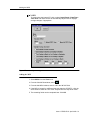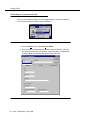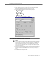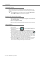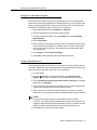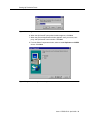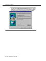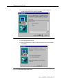
1
Conference Reservation and Control System
(CRCS) Release 6.0
Installation
555-027-109
Comcode 108382085
Issue 1
April 1999
Copyright© 1999 Lucent Technologies Inc.
All Rights Reserved
Printed in U.S.A.
Users outside of the US and Canada should contact their local
authorized Lucent Technologies distributor if they want to order
additional copies of this document. Also, users in these countries
should send any comments on the document to their local
authorized Lucent Technologies distributor.
Notice
Lucent Technologies Inc. Fraud Intervention
While reasonable effort was made to ensure that the information
in this document was complete and accurate at the time of
printing, Lucent Technologies Inc. and its authorized agents
cannot assume responsibility for errors. Changes and/or
corrections to the information contained in this document may be
incorporated in future issues. Names and addresses used for
examples throughout this guide are fictitious.
If you suspect you are being victimized by toll fraud and you need
technical support or assistance, call the BCS Technical Service
Center Toll Fraud Intervention hotline at 800 643-2353.
Comments
To comment on this document, complete and fax in the comment
card at the end of the document.
Your Responsibility for Your System’s Security
Technical Support
You are responsible for the security of your system. Lucent
Technologies Inc. does not warrant that this product is immune
from or will prevent unauthorized use of common-carrier
telecommunications services or facilities accessed through or
connected to it. Lucent Technologies Inc. will be not responsible
for any charges that result from such unauthorized use. Product
administration to prevent unauthorized use is your responsibility
and your system administrator should read all documents
provided with this product to fully understand the features
available that may reduce your risk of incurring charges.
Call:
Trademarks and Copyright Acknowledgments
Concorde is a trademark of PictureTel Corp.
DEFINITY is a registered trademark of Lucent Technologies Inc.
in the United States and throughout the world
Lotus 1-2-3 is a registered trademark of IBM
Microsoft Windows 95 and Windows NT are registered
trademarks of Microsoft Corporation
SatisFAXtion is a registered trademark of PureData
Sportster is a registered trademark of U.S. Robotics
WinFax is a registered trademark of Delrina Technology Inc.
Zetafax is a registered trademark of Equisys Limited
Screen shots of Microsoft Windows 95/NT 4.0 reprinted with
written permission from Microsoft Corporation.
Ordering Information
Call:
Lucent Technologies BCS Publications Center
Voice: 800 457-1235 International Voice: 317 322-6416
Fax: 800 457-1764 International Fax: 317 322-6699
Write: Lucent Technologies BCS Publications Center
2855 N. Franklin Road
Indianapolis, IN 46219
Order: Document No. 555-027-109
Comcode No.108392085
Issue 1, April 1999
You can be placed on a standing order list for this and other
related documents you may need. Standing order will enable you
to automatically receive updated versions of individual documents
or document sets, billed to account information that you provide.
For more information on standing orders, or to be put on a list to
receive future issues of this document, contact the Lucent
Technologies BCS Publications Center.
Video Technical Center (VTC)
800 242-2121 then follow the prompts for video
conferencing
International Technical Assistance Center (ITAC)
303 804-3777
Contents
n Installation Overview
n Upgrading from a Previous Release
2
Upgrading a Single-User System
2
1
n Pre-Installation Requirements
5
CRCS/OpCenter and OpCenterSP Checklist
5
Fax Option
6
n Configuring the PC
n Connecting the PC to the MCU
7
9
Local Connection to MCU
9
Remote Connection to MCU
10
Connection Procedure
10
Checking the Modem Settings
12
n CRCS/OpCenter Software Installation
n Testing CRCS
15
19
Logging In to CRCS
19
Setting the Time Zone
20
Adding the MCU
21
Establishing the Communications Link
22
Uploading MCU Options
24
Running the MCU Extension Utility Program
24
Adding an Endpoint
24
Adding a Conference Template
26
Adding a Company
27
Adding a Person
27
Adding a Site
28
Editing Defaults
30
Adding a Test Conference
30
n Testing OpCenter
n Faxmodem Installation
31
Windows 95
32
Windows NT 4.0
32
Installing WinFax PRO 8.0
33
Saving Faxes with WinFax Log Files
37
Setting Up Reminder Faxes
37
32
Issue 1 CRCS R6.0 April 1999
iii
Contents
n OpCenterSP Installation
n Testing OpCenterSP
n Appendix A: Modem Pooling
42
44
Administering Modem Pool Groups
44
3800 Series Modem Installation
48
3810
48
3820
53
3830
53
7400A Data Module Installation
iv
38
Issue 1 CRCS R6.0 April 1999
54
Single-User
CRCS/OpCenter and
OpCenterSP Installation
Installation Overview
CRCS/OpCenter and OpCenterSP can be set up as a single-user system on a
dedicated PC connected to up to 2 Lucent Technologies MultiPoint Conferencing
Units (MCU). The CRCS/OpCenter PC can run either Microsoft® Windows NT
4.0 or Microsoft Windows 95.
The connection between the CRCS/OpCenter or the OpCenterSP PC and the
MCU can be local if the distance between the two is less than 5000 feet. The connection is considered remote if the distance is greater than 5000 feet. Also, if the
CRCS/OpCenter or OpCenterSP PC is not connected to the TN754B or TN2224
on the MCU side, the connection is considered remote.
Follow the installation procedures outlined in this guide to set up and connect the
CRCS/OpCenter or the OpCenterSP PC to the MCU. This manual also includes
installation procedures for the fax option available with CRCS.
Issue 1 CRCS R6.0 April 1999 1
Upgrading from a Previous Release
Upgrading from a Previous Release
Each new release of the CRCS/OpCenter program and the MCU offers additional
features. If any endpoint already included in your previous release supports some
or all of the new enhancements, you may need to update the bandwidth, protocols, and feature entries in the Conference Template, Endpoint, Site, and MCU
databases.
Beginning with release 6.0, CRCS is backward compatible with the previous
release MCU. The two MCUs controlled by CRCS do not need to be the same
release. For example, MCU1 could be release 6.0 and MCU2 could be release
5.0.47.
NOTE:
If upgrading from a release earlier than CRCS 4.2, remove all reservation
system items including link manager and command manager from the
StartUp group prior to installation.
Upgrading a Single-User System
The first consideration before upgrading from an earlier release is to make sure
your hardware and operating system meets the higher minimum requirements of
the release of CRCS/OpCenter. See "Pre-Installation Requirements" for a list of
the required hardware components, software, and operating system. Also make
sure you have the list of logins and passwords as defined.
With the proper hardware installed, use the following upgrade procedure to load
the new release of CRCS:
1. Before upgrading, you need to run the database repair program. To do so,
click Start—Programs—Lucent Technologies CRCS—Run Database
Repair. If there are any errors reported, click Start—Programs—Accessories—System Tools—Scan Disk.
2. Backup the database to external media such as floppy disk, zip disk, or
tape. This database file named crs.mdb is located in the dbase subdirectory (where CRCS was previously installed). You can perform a Start—
Find to locate the file or look in your CRCS directory under the dbase
folder. It may be located on your main boot drive.
NOTE:
If you changed the name of the default directory or destination drive when
you previously installed CRCS, copy the crs.mdb file to the dbase subdirectory of the new directory before installing CRCS and readministering the
link. For example, if you name the directory c:\crcs6x, you would need to
2
Issue 1 CRCS R6.0 April 1999
Upgrading a Single-User System
create a subdirectory named c:\crcs6x\dbase and copy the crs.mdb file into
it before installing CRCS.
3. From the MCU MT, perform an add login and change permissions to create
the crcs login, password, and permissions (see MCU Administration for
details).
4. Insert the CRCS CD-ROM and click Start on the Windows Taskbar.
NOTE:
Make sure no other applications are running, including fax programs.
5. Click Run and use the Browse button to locate the setup.exe file on the
CD-ROM. Click OK.
6. Follow the program prompts (see "CRCS/OpCenter Software Installation"
on page 15 for details) and when the installation is complete, choose to exit
without the automatic reboot (the No option) and shutdown your PC.
7. Power off your PC.
8. Wait a few seconds and power on the PC.
9. Login to CRCS as an administrator.
10. From the Admin menu on the Main window, select Query MCU Parameters for each MCU (1 and/or 2).
11. Schedule a test conference to begin immediately, verify that the conference
downloads to the MCU and record the CRCS ID #.
12. From the MCU MT, perform a list conference to verify the conference
downloaded to the MCU. If the connection is established, the upgrade is
complete. For remote connections only, continue to step 13.
13. For remote connections, you can administer when the link between CRCS
and the MCU is connected. It can be connected full time (permanent), only
when a conference data is being downloaded (on-demand), or during a
specified hours in a day (between). From the CRCS PC, administer a connect time from the Admin menu on the Main window, select Run Link
Admin.
14. From the MCU Link Administration window, click the Connect Parameters
tab.
n
for the on-demand option, specify the time (in minutes) that the link
should remain connected.
n
for the between option, specify the time range when the link will be
connected. Also, for off-hours (those hours that fall outside the time
range) specify the time (in minutes) that the link should remain connected when requested.
Issue 1 CRCS R6.0 April 1999 3
Upgrading from a Previous Release
Figure 1. MCU Link Administration window
15. The upgrade process is complete and you can begin using CRCS/
OpCenter.
4
Issue 1 CRCS R6.0 April 1999
CRCS/OpCenter and OpCenterSP Checklist
Pre-Installation Requirements
As a single-user dedicated system on a PC connected to one or two Lucent Technologies MultiPoint Conferencing Units (MCU), CRCS/OpCenter or OpCenterSP
can be set up as either local or remote.
For a local connection, the distance between the PC and MCU must be less than
5000 feet. Distances beyond 5000 feet are considered remote. Also, if the PC is
not connected to the TN754B or TN2223 on the MCU side, the connection is
remote.
CRCS/OpCenter and OpCenterSP Checklist
Hardware Requirements
The system installed for single-user CRCS/OpCenter must be dedicated for
CRCS/OpCenter use only. The following hardware components are required:
n
266 MHz Pentium II CPU with 64 MB RAM or greater recommended (minimum 100 MHz Pentium with 32 MB RAM)
n
1024 by 768 pixel resolution, 256 color, and small fonts
n
One 17-inch monitor (minimum 15 inch)
n
2.5 GB hard disk with a high-speed drive and local bus controller (minimum
1.2 GB)
n
One 1.44 MB 3.5 inch floppy disk drive
n
One 6X CD-ROM drive (minimum 4X)
n
A COM1 serial port with a 25-pin connector or a 9-to-25 pin adapter, if the
COM1 port is 9 pin
n
A bus mouse or a serial mouse connected to a COM serial port
n
Optional laser or laser-quality printer connected to the LPT1 parallel port
and installed as the default printer
n
Optional (highly recommended) backup tape or high capacity removable
disk device and appropriate software for the backup
n
Slot for the fax hardware (optional)
Software Requirements
n
Microsoft Windows 95 or Windows NT 4.0 workstation with Service Pack 4
Issue 1 CRCS R6.0 April 1999 5
Pre-Installation Requirements
Remote Configurations
For remote configurations where the MCU and CRCS/OpCenter or OpCenter SP
are not collocated, modem pooling is used (see "Appendix A: Modem Pooling" on
page 44). The modems must support a minimum of 9600 baud. Additional serial
ports may be required which must support non-shared interrupts.
Login and Passwords
Be sure you know the following information:
n
Login, password, dialed number and COM port for each MCU
n
CRCS or OpCenterSP Serial Number
n
Default administrator password and agent password
n
PC login and password, if applicable
Fax Option
Refer to "Faxmodem Installation" on page 32 for hardware and software requirements for the optional fax feature.
6
Issue 1 CRCS R6.0 April 1999
Fax Option
Configuring the PC
Regardless of whether the connection between the PC and the MCU is local or
remote, you must supply the proper adapter to connect the COM1 port to the
RS232 cable.
Configure your CRCS/OpCenter or OpCenterSP PC as follows:
Figure 2. Microsoft Windows Control Panel Settings
1. With your PC powered on, select Start—Settings—Control Panel.
2. Perform each of the following steps:
n
select the Regional Setting and Keyboard to set both to English
(United States)
n
set the Display by selecting Settings to 1024 by 768 pixels, 256
color, and small fonts
Issue 1 CRCS R6.0 April 1999 7
Configuring the PC
.
Figure 3. Display Properties Window
n
select Modem and use the Modem Installation wizard to set the
modem COM ports. Click Add then Don’t detect my modem.
Under Manufacturers, choose Standard Modem Types. Under
Models, select Standard 9600 bps Modem. Choose the appropriate COM port: Communications Port (COM 1) for the MCU 1 connection and COM2 for the MCU 2 connection.
Figure 4. Install New Modem Wizard—Selecting the COM Port
8
Issue 1 CRCS R6.0 April 1999
Local Connection to MCU
Connecting the PC to the MCU
This procedure establishes the connection between the CRCS/OpCenter PC and
the data module or modem. For information about connecting the data module or
modem to the MCU, see the MCU Installation and Test manual. To connect the
PC using the standard serial ports to the modem or data module, follow these
steps:
Local Connection to MCU
The following hardware is required for a local MCU connection:
n
8400B data module (supplied)
NOTE:
7400B data module is supported from previous releases
n
M25B cable (not supplied)
n
9-pin-to-25 pin RS232 adapter (not supplied)
MCU
COM 1
RS232
Cable
8400B/7400B
PBX
Wall
Jack
PC
To
MCU
Port 1
Phone Line
D8W Cord
Figure 5. Local Connection to the MCU
Issue 1 CRCS R6.0 April 1999 9
Connecting the PC to the MCU
Remote Connection to MCU
When the PC is located remotely from the MCU, the MCU’s modem pooling capability is ideal for connecting the data link needed to support CRCS/OpCenter. With
modem pooling, Hayes-compatible analog modems are used at the PC to connect
over the PTSN to the MCU. The MCU implements an external 7400A data module
combined with a 3800 modem running 9600 bps to provide conversion resources
needed to route the analog voice calls from the CRCS to the digital Netcon channels in the MCU.
There are two types of conversion resources for modem pooling. The first type, an
integrated conversion resource, is a circuit pack which emulates a Trunk Data
Module connected to a 212A-type modem. The MCU does not support the integrated modem solution.
The second type, a combined conversion resource, is a separate Trunk Data
Module and modem administered as a unit. The Trunk Data Module component of
the conversion resource may be either a Modular Trunk Data Module (MTDM) or
a 7400A data module. The module connects to a digital port using Digital Communications Protocol (DCP); the 3800 modem connects to an analog port on the
TN746B.
The MCU supports the Combined Modem Pooling Solution for use in remote connectivity between the MCU and the CRCS module whenever these components
are not collocated. See "Appendix A: Modem Pooling" for further installation
details.
Connection Procedure
1. Connect the COM1 port to the 8400B/7400B data module with an appropriate adapter, if necessary, and an M25B (EIA-232-D) cord or equivalent. If
using modem pooling, use an analog modem instead.
2. Use an RS232 cable (M25B) with a 25-pin female connector for the CRCS
PC or server and a 25-pin male connector for the analog modem (remote
connection) or data module (local connection).
3. If your supplied cable does not have the appropriate gender connectors,
use a gender changer to make the adjustments.
4. PC ports are usually labeled with the port number and type (serial or parallel), if not see your PC user manual for proper labeling. If the first serial port
is a 9-pin connector, connect a 9-pin-to-25-pin RS232 adapter (you supply).
10
Issue 1 CRCS R6.0 April 1999
Connection Procedure
TDM Bus
TN746B
DS1
TN754B
Analog
3800
Analog
3800
DCP
7400A
DCP
7400A
RS232
Voice Grade
Data Call
Public/Private
Network
Analog
Modem
RS232
PC
Figure 6. Remote CRCS Connection to MCU (Modem Pooling)
5. Connect the female end of the RS232 cable to the male end of either an
adapter or the CRCS PC first serial port.
6. Connect the male end of the RS232 cable to the female 25-pin RS232 connector on the analog modem (remote connection) or data module (local
connection).
5000 Feet
MCU
TN754B/
TN2224
B25A Cross-Connect
at MDF
103A
or Wall
Jack
D8W
M25B
7400B/8400B
PC
Figure 7. Connecting the MCU to the CRCS PC
7. If you are using the 8400B data module (TN2224 required), go to step 8. If
you are using the 7400B data module, verify or change the following dip
switch settings:
n
For a standalone data-only 7400B data module, set dip switch #1 to
ON (UP), if no phone is connected. All other dip switches should be
set to the OFF position (DOWN);
n
If you are using a phone on a 7400B data module, set all dip
switches to the OFF position (DOWN).
8. Continue with "Checking the Modem Settings" on page 12.
Issue 1 CRCS R6.0 April 1999 11
Connecting the PC to the MCU
Checking the Modem Settings
The last step before loading the CRCS program requires that you configure and
check the modem connection to the MCU.
1. From Microsoft Windows, select Start—Programs—Accessories—
HyperTerminal.
2. From the HyperTerminal window, click the Hypertrm.exe icon.
Figure 8. HyperTerminal Window Setting
3. Enter Test in the Name field of the Connection Description window and
select the first icon as shown. Click the OK button.
4. Click on Connect Using and select Direct to COM1.
12
Issue 1 CRCS R6.0 April 1999
Checking the Modem Settings
5. Choose the following settings:
n
Connector=Com1
n
Baud Rate=9600
n
Data Bits=8
n
Stop Bits=1
n
Parity=None
n
Flow Control=None
6. Click the OK button to save the changes. If you are using the 8400B data
module, continue to step 7. For the 7400B data module, skip to step 10.
7. Type ats24=001 to set the data module for standalone operation without a
telephone.
8. Remove power from the 8400B data module for 5 seconds.
9. Reconnect power to the 8400B data module. The red LED comes on
steady.
10. Type at and press Enter. The OK prompt appears. Type atdt and the dial
number you recorded earlier. Press Enter. The login prompt appears.
Figure 9. Connection Description Window
Issue 1 CRCS R6.0 April 1999 13
Connecting the PC to the MCU
11. When the login for the MCU displays, enter the login and password
assigned by the technical center during installation to verify that you have a
working CRCS to MCU link.
12. Type logoff and exit hyperterminal. Repeat this procedure to test COM2 if
you are controlling a second MCU.
NOTE:
If the MCU login does not display, verify that the MCU recognizes that
CRCS is active (from the MT check the Scheduler Adjunct field on the customer-options form. It must be set to y).
13. Continue to "CRCS/OpCenter Software Installation" on page 15 to load the
CRCS/OpCenter program.
14
Issue 1 CRCS R6.0 April 1999
Checking the Modem Settings
CRCS/OpCenter Software Installation
NOTE:
If your system encounters a conflict with another application while running
setup, make sure all other Windows applications are closed before proceeding.
1. Complete the PC connections by connecting the power cord and plug,
inserting the mouse cord in an available COM port or installing the bus
mouse, and turning on the power.
Figure 10. Loading the CRCS/OpCenter Software
2. Insert the CRCS CD-ROM.
3. From the Windows desktop, click Start—Run....
4. From the Run window, click the Browse button to locate the CRCS CDROM setup program or type the letter assigned to the CD-ROM driver followed by a colon (:), a backslash (\), and the word setup.exe. For example:
g:\setup.exe would be the entry if the CRCS CD-ROM was inserted in
drive g. Click OK.
Figure 11. CRCS Setup—Entering the Location of the CRCS CD-ROM
Issue 1 CRCS R6.0 April 1999 15
CRCS/OpCenter Software Installation
5. When the CRCS/OpCenter setup wizard window appears, click Next.
6. When the product identification window appears, enter your name, company, and CRCS serial number. Click Next.
7. From the Select Components window, select to install Conference Scheduler and the ODBC drivers. Click Next.
Figure 12. CRCS Setup—Select Components
16
Issue 1 CRCS R6.0 April 1999
Checking the Modem Settings
8. From the Choose Destination Location window, CRCS offers install to a
path called c:\program files\lucent\crcs. If there is no directory by that
name, the setup wizard will create one for you. You can also change the
destination drive by replacing c: with the appropriate drive letter. Click
Next.
Figure 13. CRCS Setup—Destination Location
9. From the Start Copying Files window, the setup wizard displays the
selected components to be copied. Click Next.
Issue 1 CRCS R6.0 April 1999 17
CRCS/OpCenter Software Installation
Figure 14. CRCS Setup—Copying Files
10. The copying process begins. When the installation process is complete,
select to reboot your PC then click Finish.
Figure 15. CRCS Setup—Restart PC
18
Issue 1 CRCS R6.0 April 1999
Logging In to CRCS
Testing CRCS
The following procedure allows an administrator to enter minimum data to test
CRCS and the MCU connection. Refer to the online help for details on building
and maintaining the database.
Logging In to CRCS
Although CRCS continues to run even when no one is logged on, you must log in
to add, change, or otherwise work with conference data or databases. CRCS login
names and their associated passwords are assigned by the system administrator.
The default logins, admin and agent, also have default passwords (available from
your Lucent representative) associated with them. If you choose to keep the login
names admin and agent, be sure to change the default passwords for both of
them for security reasons. However, any additional logins you add do not require
a password.
1. If the Login window is not already displayed, select Start—Lucent Technologies CRCS—Conference Scheduler.
2. From the CRCS Login window, click Login.
3. Enter your login name and password.
4. Click OK.
NOTE:
Logging out of the CRCS program is not the same as exiting the program.
CRCS must run on the single-user PC in order to download scheduled conferences and perform other scheduled tasks. The CRCS program runs
even when no one is logged in. Therefore, do not exit the program except
when upgrading the CRCS database or performing a database backup or
restore. To log out, from the main window, select File—Log Out.
Issue 1 CRCS R6.0 April 1999 19
Testing CRCS
Setting the Time Zone
1. Login as an administrator.
2. The time zone where the CRCS PC is located is Local. If the CRCS controls an MCU that is not geographically located in the same time zone,
you must perform the following steps; otherwise skip to step 3:
n
Select Time Zone Template from the View menu.
n
From the Time Zone Template View window, click
n
From the Add Time Zone Template window, enter a name for the
time zone where the MCU is geographically located. Typically, you
would enter the common name for the time zone such as Eastern,
Mountain, or Central.
.
Figure 16. Selecting the Time Zone
20
n
In the Time Zone Offset section, enter the amount of time in hours
that the Local time (where the CRCS PC is located) is ahead or
behind the time where the MCU is located. For example, if the
CRCS PC is in New Jersey and the MCU is in California, the Offset
is 3 hours Behind CRCS Time.
n
Under the Daylight Savings Increment, specify if the time zone
where the MCU is located follows Daylight Savings time changes
and if so, the dates when Daylight Savings starts and ends.
n
Click OK to save the new time zone setting.
Issue 1 CRCS R6.0 April 1999
Adding the MCU
NOTE:
To synchronize the internal PC clock, select Control Panel—Date/Time—
Time Zone and check the box to automatically adjust clock for daylight
savings changes, if appropriate.
Figure 17. CRCS Setup—Adding a Time Zone
Adding the MCU
1. Select MCUs from the View menu.
2. From the View MCUs window, select
.
3. From the Add MCU window, enter 1 or 2 in the MCU ID field.
4. If the MCU is located in a different time zone than the CRCS PC, click the
down arrow to select the Time Zone Template from the drop down menu.
5. The remaining fields can be completed later. Click OK.
Issue 1 CRCS R6.0 April 1999 21
Testing CRCS
Establishing the Communications Link
After you have added the MCU, run the link administration program to establish
the connection between the MCU and the CRCS PC.
Figure 18. CRCS Database Setup—Run Link Administration
1. From the Admin menu, select Run Link Admin.
2. From the MCU Link Administration window, select the MCU (1 or 2) from
the drop-down menu that you added in "Adding the MCU" to establish the
communications link between that MCU and the CRCS PC.
Figure 19. CRCS Database Setup—MCU Status Link Administration
22
Issue 1 CRCS R6.0 April 1999
Establishing the Communications Link
3. Enter a descriptive name for the MCU. This name should help identify
which MCU is being referred to such as Denver 1 or LA 2.
4. Click the COM Port tab and check for the following settings:
n
Baud Rate=9600
n
Parity=None
n
Character Size=8
n
Stop Bits=1
n
Communication Port=Com 1 or Com 2.
Figure 20. MCU Link Administration Window (COM Port Tab)
NOTE:
Previous releases of CRCS required a different Hayes modem initialization
string than the current release. This string supports the new 8400B data
module available for this release; if you are upgrading from a previous
release and have 7400B data module, it will ignore the additional register
setting in the new string.
5. Under the Connect Parameters tab, the connection between the MCU and
CRCS PC is defaulted to Permanent. Leave this setting for testing purposes.
6. Click OK after the settings are made.
Issue 1 CRCS R6.0 April 1999 23
Testing CRCS
Uploading MCU Options
After the connection has been established between the MCU and the PC, you
need to query the MCU to send its parameters and option settings to the CRCS
program.
n
From the Admin menu on the Main window, select Query MCU Parameters for MCU1 or MCU2. The parameters are uploaded.
Running the MCU Extension Utility Program
1. Run the extension utility by clicking Start—Programs—Lucent Technologies—Extension Utility.
2. Select the MCU (MCU1 or MCU2).
3. Wait for the MCU to display that the MCU extensions have been retrieved.
Adding an Endpoint
1. Login to CRCS.
2. From the main window, click
the View menu).
(or select Endpoint Template from
3. From the View Endpoint window, notice that the Endpoint1 model endpoint is already listed. To add another make or model endpoint, click
.
4. From the Add Endpoint window, under the Name field, enter a unique
name to identify a make/model of an endpoint. If possible, choose an endpoint that the majority of conferees are using. The name you enter is arbitrary; it can be a combination of the endpoint manufacturer’s name, model
number, and release or just a word that is meaningful to you.
5. Under Supported Bandwidths, select each of the bandwidths the endpoint
supports (more than one can be selected). For testing, you may leave
some or all of the remaining fields empty and edit them later.
24
Issue 1 CRCS R6.0 April 1999
Adding an Endpoint
Figure 21. Add Endpoint Window
6. Click the OK button to add the new endpoint to the Endpoint Database.
Issue 1 CRCS R6.0 April 1999 25
Testing CRCS
Adding a Conference Template
1. From the main window, click
menu).
(or select Template from the View
2. From the View Conference Template window, notice there is a conference
template 2x56=112 2B. To add another conference template, click
.
3. When the Add Conference Template window appears, enter a descriptive
name for your conference template in the Template Name field and select
the supported bandwidth and protocol. The template name should relate to
the bandwidth and protocol being assigned to it. For example, 768K_Px64
would be an acceptable name for a supported bandwidth of 768K with the
Px64 protocol.
Figure 22. Add Conference Template Window
4. Click OK to add the conference template.
26
Issue 1 CRCS R6.0 April 1999
Adding a Company
Adding a Company
1. From the main window, click
menu).
(or select Company from the View
2. From the View Company window, notice there is already a fictional name
entered (COMPANY XYZ). To enter a new company, click
.
3. When the Add Company window appears, enter the Company Name and
address. Again for the purposes of testing, the address is optional at this
time.
Figure 23. Adding a Company
Adding a Person
1. From the main window, click
menu).
(or select People from the View
2. From the View People window, notice there is already a fictional name
entered (MCU Customer). To enter a person, click
.
3. When the Add Person window appears, enter the person’s name under
Convener’s Name and choose the associated Company Name. Again for
the purposes of testing you do not have to complete the remaining fields at
this time
Issue 1 CRCS R6.0 April 1999 27
Testing CRCS
4. Click OK to add the person..
Figure 24. Add Person Window
Adding a Site
1. From the main window, click
from the View menu).
on the main window (or select Site
2. From the View Sites window, notice there is a listing for External-1.
You can use that site for testing or click
to add one of your own.
3. When the Add Site window appears, enter a unique name for a site you
want to add. Duplicate site names are not permitted.
28
Issue 1 CRCS R6.0 April 1999
Adding a Site
Figure 25. Add Site Window (General Tab)
4. Click the Video Phone Numbers tab and enter the relevant information.
NOTE:
If adding an external site, select a Meet-Me Extension Pool but do not
assign a dialout number to it. Dialout numbers for external sites are
assigned through the Site Options window when a conference is scheduled.
5. Click the Supported Bandwidths tab. From the drop-down menu, choose
Endpoint1, the default, or another endpoint you added. If you chose
Endpoint1 make sure 2B 112K is selected on the Supported Bandwidths
window.
6. Click OK to add the site to the Site database.
Issue 1 CRCS R6.0 April 1999 29
Testing CRCS
Editing Defaults
1. Select Defaults from the View menu.
2. From the View Defaults window, click
.
3. From the Edit Defaults window, be sure to select the correct time zone
under CRCSs Time Zone Template and MCU 1 as the Preferred MCU.
Adding a Test Conference
1. To test CRCS, click
the drop-down menu.
then select the Today’s Conference from
2. From the View Today’s Conferences window, click
.
3. From the Add Conference window, complete the General tab window by
selecting the following items:
n
a convener
n
multipoint conference type
n
conference template or select Preferred Rates under
Speed Matching
n
start (current time for an immediate conference) and end time
4. Highlight External-1 (or the site you added), Audio Add-on 1, and UCC (if
available) on the Qualifying Sites column and use the right arrow to move
them to the Selected Sites column.
5. Click OK to submit the conference.
6. On the MCU MT, perform a list conference to see if the conference
appears.
30
Issue 1 CRCS R6.0 April 1999
Adding a Test Conference
Testing OpCenter
To test the OpCenter connection, follow these steps:
1. If the Login window is not already displayed, select Start—Lucent Technologies CRCS—Conference Scheduler.
2. From the CRCS Login window, click Login.
3. Enter your login name and password.
4. Click OK.
5. Schedule a test conference to begin immediately and make sure that it
downloads to the MCU.
6. From the OpCenter menu on the Main window, select Show.
7. Choose MCU1 or MCU 2 from the drop-down menu (whichever MCU is
hosting the scheduled conference).
8. From the MCU Status Board, check to see if the conference appears.
9. Right click on the conference to display the pop-up menu.
10. Select Details to display the Conference Details window.
11. Confirm the test conference settings, bandwidth, convener, sites, etc.
12. Close the Conference Details window and MCU Status Board by clicking
the x on the right side of the title bar.
Figure 26. Testing OpCenter—MCU Status Board
Issue 1 CRCS R6.0 April 1999 31
Faxmodem Installation
Faxmodem Installation
To use CRCS fax options, one or more faxmodems must be properly installed and
configured. The type of faxmodem recommended by Lucent Technologies
depends on operating system used for CRCS—Microsoft Windows 95 or
Microsoft NT 4.0.
When installing a faxmodem on a CRCS PC that manages two MCUs, connect to
COM3 or COM4. This requires either an internal modem or an external modem
Windows 95
The following faxmodem recommendations are for Microsoft Windows 95 systems:
n
US Robotics Sportster 33.6 Faxmodem (internal or external)
n
Puredata SatisFAXtion 400/400e Faxmodem (only recommended for
upgrades of CRCS)
Windows NT 4.0
The following faxmodem recommendations are for Microsoft Windows NT 4.0 systems:
n
US Robotics Sportster 33.6 Faxmodem (internal or external)
n
Zoom Faxmodem VFX28.8 (only recommended for upgrades of CRCS)
n
Multitech MT1932ZDX (only recommended for upgrades of CRCS)
NOTE:
Lucent Technologies recommends the US Robotics Sportster 33.6 Faxmodem for all new CRCS installations regardless of platform. However, if you
have one of the other faxmodems installed from a previous release of
CRCS, you may use it with CRCS 6.0. Follow the instructions in the previous CRCS Installation manual for instructions on installing the Puredata
SatisFAXtion faxmodem. For all the other modems, follow the manufacturer’s instructions to install.
32
Issue 1 CRCS R6.0 April 1999
Installing WinFax PRO 8.0
Installing WinFax PRO 8.0
If you are upgrading from an earlier release of CRCS that uses WinFax PRO 7.5,
CRCS 6.0 will also support that software version and the faxmodems installed
according to the instructions found in the CRCS Installation manual that came
with your previous release.
NOTE:
WinFax 7.5 is only compatible with Microsoft Windows 95 platforms; use
WinFax 8.0 if installing on a Microsoft Windows NT 4.0 workstation.
1. Install your faxmodem according to manufacturer instructions and connect
to COM2.
NOTE:
If CRCS is managing two MCUs, install the faxmodem on COM3 or COM4.
This requires either an internal modem or installation of a serial card to use
an external modem.
2. Close all programs and insert the WinFax PRO 8.0 CD-ROM into your
CRCS PC.
3. If AutoPlay is enabled, the program loads automatically. Otherwise, run
setup.
4. Select the INSTALL WINFAX PRO option.
5. Select INSTALL NOW.
6. Read the licensing agreement and click Next.
7. Read the Introduction screen and click Next.
8. From the WinFax PRO Setup - User Information window, enter your name
and company and click Next.
9. From the WinFax PRO Setup - Installation Type window, select Typical
Installation and click Next.
Issue 1 CRCS R6.0 April 1999 33
Faxmodem Installation
Figure 27. Setting Up WinFax PRO
10. From the WinFax PRO Setup - WinFax Program window, clear the TalkWorks component but keep WinFax checked. Change the installation
directory as desired and click Next
34
Issue 1 CRCS R6.0 April 1999
Installing WinFax PRO 8.0
.
Figure 28. WinFax PRO Setup—Dialing Preferences
11. From WinFax PRO Setup - Dialing Preferences window, enter the fax and
phone information. If you need to dial a number to reach an outside line,
enter it in the Use prefix edit box. When complete, click Next.
12. From the WinFax PRO Setup - Modems window, select the modem that
you installed from the section Installing a Modem and click Next.
13. From the WinFax PRO Setup window, make sure that the modem is connected and power is on then click Next. The program will check that your
modem is installed properly.
14. After the installer verifies your modem is working, click Next.
NOTE:
If you have a previous version of WinFax already installed, the installer will
notify you that it is installing over the previous version. Follow the instructions provided on screen.
15. From the WinFax PRO Setup - Install Microsoft Exchange window, CRCS
6.0 does not require Microsoft Exchange. Click Next.
Issue 1 CRCS R6.0 April 1999 35
Faxmodem Installation
Figure 29. WinFax PRO Setup—CSID
16. From WinFax PRO Setup - CSID window, enter any combination of text
and numbers for the Class ID (CSID). Enter your voice phone number in
the Voice number field and click Next.
17. From the WinFax PRO Setup - Default Printer window, select No and click
Next.
18. For Windows NT 4.0 installations only: From the WinFax PRO Setup - NT
Service window, enter the password for the account that was used to log on
and click Next.
19. From WinFax PRO Setup - Program Group window, the new program
group is listed as it will appear in the start bar and click Next.
20. If you want to register WinFax PRO online, from the WinFax PRO Setup Online Registration window, select Yes. If not, select No.
21. The finish screen appears. Click on Finish and the installer will put WinFax
PRO onto the CRCS PC.
22. If you selected Yes to register WinFax online, the installer will prompt for
information and then attempt to send it over the modem.
23. When prompted to restart the computer, select restart.
24. For Windows NT installations, log on as the same user.
36
Issue 1 CRCS R6.0 April 1999
Saving Faxes with WinFax Log Files
Saving Faxes with WinFax Log Files
WinFax PRO saves faxes you send, even when they are not successfully transmitted. A list of sent faxes appears in the WinFax Send Log. If you no longer need
copies, periodically delete them to free up the disk space. You can also set WinFax PRO to automatically delete old faxes for you as follows:
1. Start WinFax PRO and choose Setup then Program.
2. Click the Log button on the Program Setup window.
3. From the Log Setup window, check the Enable item under Automatic
Event Deletion.
4. Choose All Events.
5. Enter a number in the Age by box (the number represents how old in days
the faxes are being deleted). For example, enter 7 to delete all faxes that
are at over a week old (8 days). The deletion occurs automatically when
you start WinFax.
6. Under Delete, choose Events and Pages.
7. Select OK on the Log Setup and Program Setup windows.
Setting Up Reminder Faxes
The reminder fax option for CRCS gives you the ability to send reminder faxes to
conveners. CRCS also controls when those faxes are transmitted. An admin level
login is required to administer this option if it is provisioned.
1. Log into CRCS.
2. From the Admin menu on the Main window, select Reminder Fax
Options. (If this option is dimmed it is not provisioned for your CRCS).
3. Click on Enable the sending of reminder faxes for Convener. To disable
this feature, click Disable.
4. Type or scroll to a value between 1 and 14 to set the number of days before
a conference begins that the reminder should be sent.
5. Type or scroll to a time the fax reminder should be sent to the recipient
(convener). The line below this setting confirms the date and time selected.
NOTE:
Sending fax reminders consumes a substantial portion of CRCS
resources. Try to have faxes transmitted during a time when CRCS is not
needed for other activities (late evening/early morning). It is best not to use
CRCS for making reservations while fax reminders are being sent.
6. Select OK to save the fax reminder settings.
Issue 1 CRCS R6.0 April 1999 37
OpCenterSP Installation
OpCenterSP Installation
NOTE:
If your system encounters a conflict with another application while running
setup, make sure all other Windows applications are closed before proceeding. If no other program is running when a conflict is reported, remove
OpCenterSP and related programs, including Link Manager, from your
Windows Startup group and reboot your PC before trying setup again.
1. Setup your OpCenterSP PC as described under "Pre-Installation Requirements" on page 5 and configure the PC according to "Configuring the PC"
on page 7.
2. Complete the OpCenterSP PC to MCU connections as described in "Connecting the PC to the MCU" on page 9 by connecting the power cord and
plug, inserting the mouse cord in an available COM port or installing the
bus mouse, and turning on the power.
Figure 30. Loading OpCenterSP Software
3. Insert the CRCS CD-ROM.
4. From the Windows desktop, click Start—Run....
5. From the Run window, click Browse to locate the CRCS CD-ROM setup
program or type the letter assigned to the CD-ROM driver followed by a
colon (:), a backslash (\), and the word setup.exe. For example:
g:\setup.exe would be the entry if the CRCS CD-ROM was inserted in
drive g. Click OK.
38
Issue 1 CRCS R6.0 April 1999
Setting Up Reminder Faxes
Figure 31. Entering the Location of the CRCS CD-ROM
6. When the OpCenterSP setup wizard window appears, click Next.
7. When the product identification window appears, enter your name, company, and OpCenterSP serial number. Click Next.
8. From the Select Component window, select to install OpCenter and ODBC
drivers. Click Next.
Figure 32. OpCenterSP Setup—Select Components
Issue 1 CRCS R6.0 April 1999 39
OpCenterSP Installation
9. From the Choose Destination Location window, OpCenterSP offers install
to a path called c:\program files\lucent\opcenter. If there is no directory
by that name, it will create one for you. You can also change the destination drive by replacing c: with the appropriate drive letter. Click Next.
Figure 33. OpCenterSP Setup—Choose Destination Location
40
Issue 1 CRCS R6.0 April 1999
Setting Up Reminder Faxes
10. From the Start Copying Files window, the setup wizard displays the
selected components to be copied. Click Next.
Figure 34. OpCenterSP Setup—Copying Files
11. The copying process begins.
12. When the installation process is complete, select to reboot your PC then
click Finish.
Figure 35. OpCenterSP Setup—Restart PC
Issue 1 CRCS R6.0 April 1999 41
Testing OpCenterSP
Testing OpCenterSP
OpCenterSP login names and their associated passwords are assigned by the
system administrator. The default logins, admin and agent, also have default
passwords (available from your Lucent representative) associated with them. If
you choose to keep the login names admin and agent, be sure to change the
default passwords for both of them for security reasons. However, any additional
logins you add do not require a password.
1. If the Login window is not already displayed, select Start—Lucent Technologies OpCenter—OpCenter.
2. From the OpCenterSP Login window, click Login.
3. Enter your login name and password.
4. Click OK.
5. From the Link Administration window, set up each MCU.
Figure 36. MCU Link Administration Window
42
Issue 1 CRCS R6.0 April 1999
Setting Up Reminder Faxes
6. Click OK and the MCU1 and/or MCU 2 Status Boards will appear.
7. To test the OpCenterSP link, try entering a dedicated conference on the
MCU MT and watch the appropriate MCU Status Board for an update
regarding the test conference.
Figure 37. Testing OpCenterSP—MCU Status Board
Issue 1 CRCS R6.0 April 1999 43
Appendix A: Modem Pooling
Appendix A: Modem Pooling
Administering Modem Pool Groups
The commands in the following table are used to access the Modem Pool Groups
form:
Table 1. Modem Pool Groups Command
Action
Object
Qualifier
add
modem-pool num
1 to maximum
change
modem-pool num
1 to maximum
display
modem-pool num
1 to maximum,
print or schedule
list
modem-pool num
print or remove
remove
modem-pool num
1 to maximum
Qualifier “maximum” is the maximum number available in your system configuration.
To change information associated with modem pool groups, follow these steps:
1. From the MCU MT, at the command prompt enter change modem-pool
num.
2. Verify the screen displays the Modem Pool Groups form.
3. Use TAB and RETURN to advance to the fields you want to change.
4. Submit the form.
5. To verify the form, enter display modem-pool num.
44
Issue 1 CRCS R6.0 April 1999
Administering Modem Pool Groups
Figure 38. Display Modem-Pool Screen
The following list describes the fields on the Modem Pool Groups form:
n
Group Number: This display-only field appears whenever the form is
accessed via add or change administration command.
n
Group Type: Enter combined.
n
Hold Time (min): Enter the maximum number of minutes (1 through 99) that
a conversion resource in the group may be held while a call waits either in
a queue or reserved after Data Call Preindication. Default is 5.
n
Modem Name: Enter a 1 to 6 alphanumeric character string to indicate the
name of the modem pool (preferably “ResCen” for ResCenter and “OpCen”
for OpCenter).
Issue 1 CRCS R6.0 April 1999 45
Appendix A: Modem Pooling
Figure 39. Add Modem-Pool Screen
The following fields may be assigned for the Combined Modem Pooling solution:
46
n
Speed: Enter one, two, or three communication speeds in bits per second
of the conversion resources in the group. Speeds include LOW, 0 to 300
blind sampled, 300, 1200, 2400, 4800, 9600, or 19200. Separate entries
with more than one speed with slashes (for example, 300/1200/2400,
which indicates a maximum of three running speeds). For CRCS connectivity, enter 9600. Default is LOW/300/1200.
n
Duplex: Enter full or half to indicate the duplex mode of the conversion
resources in the group. For CRCS connectivity, enter full. Default is full.
n
Synchronization: Enter sync or async to indicate the synchronization
mode of the conversion resources in the group. For CRCS connectivity,
enter asynch. Default is async.
Issue 1 CRCS R6.0 April 1999
3800 Series Modem Installation
The Port Pair Assignments area contains the following field:
n
Analog Digital: Enter the port numbers of the modem/TDM pair in a conversion resource. Two port entries are required. Include seven characters for
each entry. Use the following values
Table 2. Port Assignments
Character
Position
Meaning
Value
1-2
cabinet number
01 through 03
3
carrier
A through E
4-5
slot number
01 through 20
6-7
circuit number
01 through 32
3800 Series Modem Installation
3810
The 3810 modem should be installed in permissive mode. Insert a 4-conductor
modular plug into the jack labeled DIAL/LEASED (3820). The following table
shows the 3810 option settings for 9600 bps:
Issue 1 CRCS R6.0 April 1999 47
Appendix A: Modem Pooling
Table 3. 3800 Series Modem Installation
Activ (Operating)
DTE_Interface
48
Option
Selection
AT Command
Asynch/Sync Mode
Async
AT&M..
Async DTE Rate
9600
AT..
Asyn #Data Bits
8
AT..
Asyn Parity Bit
None
AT..
Asyn #Stop Bits
1
AT..
DTR Action
Stndrd_RS232
AT&D..
DSR Control
Stndrd_RS232
AT&S..
RTS Action
Ignore
AT&R..
CTS Control
Forced_On
AT\D..
RTS/CTS Delay
0 msec
S26=0
LSD Control
Stndrd_RS232
AT&C..
Tx Clock Source
Internal
AT&X..
Bakup_TXC1k_Src
Internal
CT111_Rate Cntl
Disable
S61=0
DTE_Rate=VF
Disable
S90=0
Issue 1 CRCS R6.0 April 1999
3800 Series Modem Installation
Table 3. 3800 Series Modem Installation — Continued
Activ (Operating)
DTE_Dialer
Option
Selection
AT Command
DTE Dialer Type
AT
AT&M..
AT Escape Char
128
S2=128
Escape GuardTime
1000 msec
S12=50
BreakForceEscape
Disable
AT\K..
CommandCharEcho
Disable
ATE..
CarriageRtn Char
13
S3=13
Backspace Char
8
S5=8
Linefeed Char
10
S4=10
Result Codes
Enable
ATQ..
ExtendResltCode
Use_DTE_Rate
ATX..
ResultCode Form
Numbers (2)
ATV..
V25bis Coding
ASCII
S62=0
V25bis IdleFill
Mark
S63=0
V25b NewLineChr
CR+LF
S64=0
AT Cmnd Mode
Normal
S84=0
Issue 1 CRCS R6.0 April 1999 49
Appendix A: Modem Pooling
Table 3. 3800 Series Modem Installation — Continued
Activ (Operating)
Line_Dialer
Dial_Line
50
Option
Selection
AT Command
AutoAnswerRing#
1
S0=1
Dialer Type
Tone
ATT ATP
DialTone Detect
Enable
ATX..
Blind Dial Pause
2 sec
S6=2
BusyTone Detect
Enable
ATX..
BusyTone Pause Time
2 sec
S8=2
NoAnswer Timout
45 sec
S7=45
Fast Disconnect
Disable
S85=0
Line Crnt Disc
Enab (>8 msec)
S65=0
Long Space Disc
Disable
ATY..
No Carrier Disc
2000 msec
S10=20
No Data Disc
Disable
AT\T..
NoDataDiscTrig
TXD and RXD
S80=0
MakeBusyVia DTR
Disable
S69=0
MI/MIC Dialing
Disable
S83=0
Dial Line Rate
9600
S41=3
V32bis Automode
Enable
S78=0
V32bis Autorate
Enable
S76=0
Dial Tx Level
Permissv (-9)
AT&I/&J
V22b Guard Tone
Disable
AT&G..
V32bis Train
Long
S43=0
FallFwdDelay
Disable
Issue 1 CRCS R6.0 April 1999
3800 Series Modem Installation
Table 3. 3800 Series Modem Installation — Continued
Activ (Operating)
Leased_Line
V42/MNP/Buffer
Option
Selection
AT Command
Leased Mode
Disable
AT&L..
LeasedLine Rate
19200 (V32t)
S44=18
V32bis Autorate
Enable
S82=0
Leased TX Level
0 dBm
S45=0
BdLn Auto Orig
Disable
S46-0
Rate Auto Orig
Disable
S36=0
Auto Redial
Dir 1
S37=0
AutoDialStandby
Disable
S47=0
CarrierOn Level
-43dBm
S48=0
V29 TrainOnData
Disable
S92=0
FallFwdDelay
Disable
Err Contrl Mode
V42/MNPorBfr
AT\N..
V42bis Compress
Enable
AT”H..
MNP5 Compress
Disable
AT%C..
EC Negotiat Bfr
Disable
AT\C..
EC Fallbck Char
13
AT%A..
Flw Cntl of DTE
CTS_to_DTE
AT\Q..
Flw Cntl of Mdm
Disable
AT\Q..
XON/XOFF Psthru
Disable
AT\X..
Mdm/Mdm FlowCtl
Disable
AT\G..
Break Buffr Ctl
Keep_Data
AT\K..
Send Break Cntl
Data_First
AT\K..
TXBuffDiscDelay
10 sec
S49=10
RXBuffDiscDelay
Disable
S39=0
Max Frame Size
256
AT\A..
ARQ Window Size
Auto Adjust
S89=0
CellularEnhance
Disable
S91-0
Issue 1 CRCS R6.0 April 1999 51
Appendix A: Modem Pooling
Table 3. 3800 Series Modem Installation — Continued
Activ (Operating)
Test
Misc
Option
Selection
AT Command
DTE RL (CT140)
Disable
S51=0
DTE LL (CT141)
Disable
S52=0
Test Timeout
Disable
S18=0
Rcv Remote Loop
Enable
AT&T..
V54 Address
Disable
S53=0
V54 Device Type
Peripheral
S54=0
StrapsWhenDisc
No_Change
S88=0
Speaker Control
OnUntilCarr
ATM..
Speaker Volume
Medium
ATL..
Access frm Remt
Enable
S55=0
Dir#1_Callback
Disable
S67=0
If you begin with the Async_Dial Factory default option settings, then the AT commands and Diagnostic Control Panel LCD command sequences to option the
options are as shown in the following list:
52
n
Clear options/registers to factory default: &F0 (Configure/Factory)
n
DTR call control is enabled: &D2 (Configure/Edit/DTE Interface)
n
DSR tracks data set ready: &S1 (Configure/Edit/DTE Interface)
n
Numeric form (2) of result codes is enabled: V2 (Configure/Edit/DTE
Dialer)
n
Extended Result Codes set to Use_DTE_Rate: X7 (Configure/Edit/DTE
Dialer)
n
Long space disconnect is disabled: Y0 (Configure/Edit/Line Dialer)
n
MNP5 Compress is disabled: %C0 (Configure/Edit/V42/MNP/Buffer)
n
Dial Line Rate is set to 9600 bps: S41=3 (Configure/Edit/Dial Line)
n
Disable the AT Escape Char option: S2=128 (Configure/Edit/DTE Dialer)
n
Command echo is disabled: E0 (Configure/Edit/DTE Dialer)
n
Store option/register changes to Active(Save): &W0 (Configure/Save)
Issue 1 CRCS R6.0 April 1999
3800 Series Modem Installation
The recommended order of execution of AT commands if executed one at a time
is as listed above due to the loss of command echo towards the bottom of the list.
Alternatively, the single command “AT&F0 &D2 &S1 V2 X7 Y0 %C0 S41=3
S2=128 E0 &W0” can be executed.
When the 7400A data module is optioned for more than one speed it is necessary
to set the modems’ ExtendResltCode to “Use_DTE_Rate.” One would suspect
that the modems’ DialTone Detect and BusyTone could be “Disable” in a modem
pooling application, but using the AT command “X7” to set the ExtendResltCode
to “Use_DTE_Rate” automatically enables DialTone and BusyTone Detect. That is
why they are optioned as enabled here (as well as being the factory default).
To run at speeds other than 19200 bps the DTE Rate and Dial Line Rate should
be changed. Note that the AT prefix determines the asynchronous DTE Rate (as
well as the Number of Data Bits, Parity, and Number of Stop Bits). The corresponding LCD command sequence for DTE Rate is under Configure/Edit/DTE
Interface. The AT command for Dial Line Rate is “s41=r,” where r is the new rate.
The corresponding LCD command sequence for Dial Line Rate is under Configure/Edit/Dial Line. The 3800 series modems have large buffers and perform
speed conversions well.
Administrators may want to disable the AT Escape Char option. This prevents
users from changing straps. This option is disabled by setting AT Escape Char to
128. The default value is 43 (i.e., a + sign).
3820
The 3820s should be installed in permissive mode. Insert a 4-conductor modular
plug into the jack labeled DIAL/LEASED (3820). Option settings with equivalent
AT command and Diagnostic Control Panel LCD command sequences are as provided for 3810 above.
3830
The command “at i1” displays the firmware revision number and “at i19” displays
the revision number. The 3830s should be installed by inserting a 4-conductor
modular plug into the jack labeled LINE. Option settings by AT commands are as
provided for the 3810 above. To verify the modem settings on a 3830 since the
modem does not have an LCD display panel, use the following commands:
n
AT&V0 to view active (operating) configuration options
n
AT&V1 to view active (saved) configuration options
Issue 1 CRCS R6.0 April 1999 53
Appendix A: Modem Pooling
7400A Data Module Installation
The 7400A data module should be installed for DTE operation by placing the EIA
connector board in its slot so that DTE reads from the front.
In a single standalone DTE operation only AT-command modems may be used,
therefore the AT control option should be set to ON. Option settings are shown on
the following list:
It is required that 9600 speed be ON for modem pooling for CRCS.
54
n
300 speed = ON
n
1200 speed = ON
n
2400 speed = ON
n
4800 speed = ON
n
9600 speed = ON
n
19200 speed =ON
n
AT CONTROL = ON
n
CI LEAD = OFF
n
CI2 LEAD = OFF
n
CH LEAD = OFF
n
CH2 LEAD = OFF
n
LL LEAD = OFF
n
REMOTE LOOP = GRANT
n
RL LEAD = OFF
n
SIGLS DISC = ON
n
TM LEAD = OFF
Issue 1 CRCS R6.0 April 1999