1
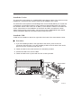
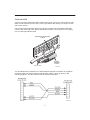
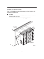
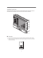
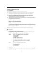
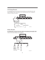
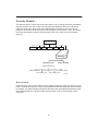
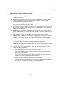
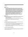
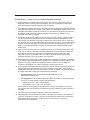
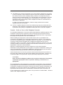
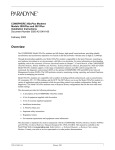
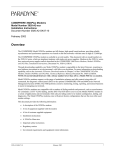
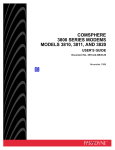
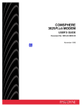
COMSPHERE 3821Plus MODEM QUICK REFERENCE Document No. 3821-A2-GL10-00 Copyright 1998 Paradyne Corporation. All rights reserved. Printed in U.S.A. Notice This publication is protected by federal copyright law. No part of this publication may be copied or distributed, transmitted, transcribed, stored in a retrieval system, or translated into any human or computer language in any form or by any means, electronic, mechanical, magnetic, manual or otherwise, or disclosed to third parties without the express written permission of Paradyne Corporation, 8545 126th Ave. N., Largo, FL 33773. Paradyne Corporation makes no representation or warranties with respect to the contents hereof and specifically disclaims any implied warranties of merchantability or fitness for a particular purpose. Further, Paradyne Corporation reserves the right to revise this publication and to make changes from time to time in the contents hereof without obligation of Paradyne Corporation to notify any person of such revision or changes. Changes and enhancements to the product and to the information herein will be documented and issued as a new release to this manual. Warranty, Sales, and Service Information Contact your local sales representative, service representative, or distributor directly for any help needed. For additional information concerning warranty, sales, service, repair, installation, documentation, training, distributor locations, or Paradyne worldwide office locations, use one of the following methods: Via the Internet: Visit the Paradyne World Wide Web site at http://www.paradyne.com Via Telephone: Call our automated call system to receive current information via fax or to speak with a company representative. — Within the U.S.A., call 1-800-870-2221 — Outside the U.S.A., call 1-727-530-2340 Trademarks All products and services mentioned herein are the trademarks, service marks, registered trademarks or registered service marks of their respective owners. Document Feedback We welcome your comments and suggestions about this document. Please mail them to Technical Publications, Paradyne Corporation, 8545 126th Ave. N., Largo, FL 33773, or send e-mail to [email protected]. Include the number and title of this document in your correspondence. Please include your name and phone number if you are willing to provide additional clarification. TM COMSPHERE 3821Plus Modem Quick Reference Document Number 3821-A2-GL10-00 December 1998 Product Documentation on the World Wide Web We provide complete product documentation online. This lets you search the documentation for specific topics and print only what you need, reducing the waste of surplus printing. It also helps us maintain competitive prices for our products. Complete documentation for this product is available at www.paradyne.com. Select Service & Support → Technical Manuals → Business Class Analog Modems. Select the following document: 3821-A2-GB30 COMSPHERE 3821Plus Modem User’s Guide To request a paper copy of a Paradyne document: Within the U.S.A., call 1-800-PARADYNE (1-800-727-2396) Outside the U.S.A., call 1-727-530-8623 3821Plus Installation A typical 3821Plus installation requires the following equipment: Eight 3821Plus cards One DTE interface assembly with 24 ports One Network Interface Module (NIM) with a 50-position short ribbon cable Three DTE (RS-232D) cables or three 8-position modular cables with six 8-position modular to DB25 adapters for each 3821Plus card One 50-position to network interface cable for each NIM A 66A-punchdown block or RJ11 gang box If any hardware components are damaged, notify your sales representative. Before installing your modem, read the Important Safety Instructions on page 21. 1 Install the Carrier The 3821Plus card resides in a COMSPHERE 3000 Series Carrier. The carrier must be installed in a rack before the modem cards can be installed in the carrier. The 3821Plus card requires a Shared Diagnostic Control Panel (SDCP) for control and configuration of individual modems. It also requires a Shared Diagnostic Unit (SDU) if the modems will be under control of an NMS, or if the SDCP is used for more than one carrier. Instructions for the installation of the SDCP and SDU, as well as the 3000 Series Carrier and its power supply, can be found in the COMSPHERE 3000 Series Carrier Installation Manual, Document Number 3000-A2-GA31. Install the NIM A NIM can be installed on the left or right side of the back of the 3000 Series Carrier. Procedure 1. If you are installing a NIM on the right side of the carrier, press it onto the connectors P24 and P23. If you are installing a NIM on the left side of the carrier, press it onto the connectors P26 and P25. 2. Fasten the NIM to the carrier with the four standoffs provided. 3. Position the NIM cover over the NIM. 4. Fasten the NIM cover in place with the four screws provided. STANDOFF NIM COVER P24 P26 J2 P25 P22 P23 P20 P19 J1 P21 TO P23 OR P25 2 TO P24 OR P26 NETWORK INTERFACE MODULE (NIM) 98-14854b Cable the NIM Connect one end of the short ribbon cable to the 50-pin connector at the bottom of the NIM. Connect the other end to P21 (on the right side of the carrier) or P22 (on the left side of the carrier). Connect a network interface cable to the 50-pin connector in the middle of the NIM. Connect the other end to the dial or leased-line interface. This may be an RJ11 gang box or a 66A-punchdown block. NETWORK INTERFACE CABLE SHORT RIBBON CABLE P21 or P22 495-14798 A 2-wire leased line connection to a JM8 interface requires a 6-position to 8-position crossover cable, such as Paradyne Part Number 3000-F1-006, as shown in the following diagram. See the User’s Guide for further information. 3 Attach the DTE Interface Assembly The 8-slot DTE interface assembly can be mounted on the left or the right side of the carrier. If you are installing only one interface assembly, it must be mounted on the same side you installed the NIM. Procedure 1. Feed the eight tabs at the bottom of the DTE interface assembly into the slots on the left or right side of the carrier. 2. Insert the screws provided, but do not completely tighten them. 3000 SERIES CARRIER A A A A A B A B A B B B C B C B C C C C C BACKPLATE ASSEMBLY TABS SLOTS 98-14799a 4 Install the Circuit Card Slide the 3821Plus card into its slot in the 3000 Series Carrier. Press firmly until the back edge of the card seats in the socket of the DTE interface assembly. 495-14797 Procedure 1. Turn the circuit pack lock until it is vertical, locking the 3821Plus card in place. 2. When all cards are installed and locked in place, tighten the screws on the DTE interface assembly. Front Panel 495-14800 5 Connect the DTE To connect the DTE to the modem, you can use two DB25 to 8-position modular adapters and an 8-pin RJ45-type modular cable instead of an RS-232 cable with DB25 connectors. Because of the large number of cables required for typical 3821Plus installations, the slimmer modular cable is recommended. The connectors on the DTE interface assembly are labeled, from top to bottom, A, B, and C. These markings show which modem on a card is associated with each connector. " Procedure 1. Connect the DB25 adapter or the connector on an RS-232 DTE cable to one of the DB25 connectors on the DTE interface assembly. Use a small screwdriver to fasten the connector to the backplate. 2. Connect the DB25 adapter or connector on the cable to the DB25 connector on the DTE. Use a small screwdriver to fasten the cable to the DTE. Install Communications Software A computer commands and controls a modem through communications software. This software uses the AT command set to send instructions to the modem. A dumb asynchronous terminal, however, does not require this software since it can directly send AT commands. The 3821Plus can be used with any major communications software. Refer to your software’s user’s guide for installation procedures. Select Factory Configuration Options After the modem passes the power-up self-test, configure it for operation using one of the factory preset configurations. The 3821Plus modem has several factory preset templates that contain the most commonly used configuration options (straps) for: H Asynchronous Dial (shown as Async Dial on the SDCP) H Synchronous Dial (Sync Dial) H Synchronous Leased (Sync Leased, Answer or Originate mode) H UNIX hardware network (UNIX Dial) H Cellular mobile (Cellular(Mobile)), valid only if ETC is installed H Cellular PSTN (Cellular(PSTN)), valid only if ETC is installed Your modem is shipped from the factory with the Async Dial default configuration options stored in memory. If Sync Dial, Sync Leased, UNIX Dial, or Cellular is more appropriate for your configuration, then you must change the factory setting using either the SDCP or the AT command set as described in the following sections. 6 Selecting Configurations Using the SDCP The SDCP’s Liquid Crystal Display (LCD) consists of two 16-character lines which display modem status, control functions, and configuration options as well as indicating your location in the Top-Level menu tree. To change the factory template for each modem using the SDCP, perform the following steps: Procedure 1. At the top level of the menu structure, select Modem A, B, or C by pressing F1, F2, or F3. 2. Press the key until Configure comes into view. 3. Press the function key below Configure to select the Configure branch. The LCD now displays Ld EditArea frm. key until Factory comes into view. Press the F1 key to display the 4. Press the factory preset configurations. Factory preset configurations are Async Dial, Sync Dial, Sync Leased, UNIX Dial, and, if ETC is installed, Cellular(Mobile), and Cellular(PSTN). If Sync Leased is selected, you must choose either Answer or Originate mode. key until the appropriate factory preset appears on the LCD, and 5. Press the press the corresponding function key to select your choice. 6. Choose Function appears and displays the Edit and Save functions. 7. Press the F3 key (Save) to save the new factory preset configuration to one of three configuration areas, Active (Saved), Customer 1, or Customer 2. (These three configuration areas are nonvolatile memory locations. Active (Saved) contains the most recently saved changes to any configuration options. In the event of power loss, the modem retrieves these configuration options. Customer 1 and Customer 2 are user-defined configuration areas.) The LCD now displays Sav EditArea to. key until the appropriate configuration area appears on the LCD, 8. Press the then press the corresponding function key to select your choice. (Saving configuration options to the Active (Saved) configuration area automatically saves them to the Active (Operating) configuration area.) The LCD displays Command Complete. 9. The modem is now configured with the selected factory template. Press the key to return to the Top-Level menu. 7 Selecting Configurations Using AT Commands When using AT commands, the following criteria must be met: H Make sure the asynchronous DTE’s communication software is configured for 10-bit character format (for example, 8 data bits, no parity, and 1 stop bit). H Make sure the DTE (RS-232D) cable is attached to the DTE connector at the rear of the COMSPHERE 3000 Series Carrier, and to the correct serial communications port on the asynchronous DTE. H On initial power-up, the modem is in Command mode. To verify that the modem is connected and functioning properly: TYPE: AT Press Enter. The screen displays OK. NOTE: If you have already changed the factory preset configuration you may have lost AT command control. To regain AT command control, select, via the SDCP, the Async Dial factory preset configuration. To change a factory template using AT commands, perform the following steps. " Procedure 1. Use the AT&F&W command to load the appropriate factory configuration to the appropriate storage area. Enter the following: TYPE: Where: AT &Ff &Wn (in all uppercase or all lowercase) f is one of the following Factory configurations: 0 for Async Dial 1 for Sync Dial 2 for Sync Leased (Answer) 3 for UNIX Dial 4 for Sync Leased (Originate) 5 for Cellular (Mobile) (valid only if ETC is installed) 6 for Cellular (PSTN) (valid only if ETC is installed) and Where: n is one of the following storage areas: 0 for Active (Saved) 1 for Customer 1 2 for Customer 2 2. Press Enter. 3. The selected factory configuration is saved. You can view the active configuration with the &V command. 8 Menu Structure An elaborate menu of options is available from a Shared Diagnostic Control Panel (SDCP). (Modem Status) MDMA mdmb mdmc Status Call_Setup Test Configure Control Remote Security 495-14520-01 Modem Select Branch The Modem Select branch is the top level of the menu structure. The modem selections are displayed when the SDCP is first connected to a 3821Plus card (using the Select key on the SDCP). Idle : 33.6 > MDMA mdmb mdmc F1 F2 F3 Press F1, F2, or F3 to connect the SDCP to modem A, B, or C, respectively. The connected modem appears on the SDCP in all uppercase characters. Quick Configuration Display To access the Quick Configuration display from the Top-Level display, press the key. If the modem is operating with V.34 modulation, a screen similar to the following appears. See the User’s Guide for the meaning of each field on the screen. 33.6 3429 10 > C001 ALO P1 V34 F1 F2 F3 9 Call Setup Branch The Call Setup branch of the Top-Level menu allows you to dial, disconnect, and answer telephone calls. It also allows you to create and store up to 10 telephone numbers to directory locations. (Modem Status) MDMA mdmb mdmc Status Test Configure Control Remote Security Call_Setup Answer Dial Disconnect Change_Directory Directory Locations 1 – 10 495-14843 Status Branch The Status branch of the Top-Level menu allows you to view the current status of the dial or leased-line connection, the DTE interface, and the identity (for example, serial number and model number) of your equipment. (Modem Status) MDMA mdmb mdmc Test Call_Setup Configure Control Remote Security Status VF Identity Ser# SigQual Mod # RcvLev Sig/Noise FRev NearEcho HPt# FPt# FarEcho FarEchDel Country EchoFreqOff DTE Options LSD DTR DSR Tst TXD RXD RTS CTS Record Display Clear 98-14844-01 10 Test Branch The Test branch of the Top-Level menu allows you to initiate various modem tests. Use these tests if you are having data communication problems, such as periodic character loss, random errors, or constant format errors. By the process of elimination, you can usually isolate the fault in your system. (Modem Status) MDMA mdmb mdmc Call_Setup Status Configure Control Remote Security Test Abort Loc_Analog_Loop Self Loc_Digital_Loop Rem_Digital_Loop Pattern 494-14855 11 Configure Branch After installing a 3821Plus modem, you set its software configuration options using either the SDCP or the AT command set. This section describes how to access and use the Configure branch of the Top-Level menu via the SDCP. (Modem Status) MDMA mdmb mdmc Status Call_Setup Test Control Remote Security Configure Ld EditArea frm: Factory Activ (Operating) Customer2 Customer1 Async_Dial Active (Saved) *Cellular Sync_Leased Sync_Dial (PSTN) UNIX_Dial Choose Mode *Cellular (Mobile) Answer Originate Choose Function Edit Save Active (Saved) Customer1 DTE_Interface Line_Dialer Leased_Line DTE_Dialer Customer2 Test Security Dial_Line V42/MNP/Buffer Misc 98-14845-01 *Available if ETC is installed 12 Control Branch The Control branch of the Top-Level menu allows you to manage hardware and software functions, such as speaker volume, reset, busy out, and firmware download. The 3821Plus modem has the additional hardware function, Service Line. To access Control from the Top-Level menu, press the Select Control. key until Control appears. (Modem Status) MDMA mdmb mdmc Call_Setup Status Test Configure Remote Security Control Reset Service_Line or Make_Busy DiscServLine Download or Code RemoveMakeBusy 495-14846 Remote Branch The Remote Access feature of 3821Plus modems allows you to change configuration options and control test functions in a remote 3821Plus modem from any COMSPHERE 3800, 3800Plus, or 3900 Series modem with a Diagnostic Control Panel (DCP) or a Shared Diagnostic Control Panel (SDCP). Remote access is only available when using V.34, V.32terbo, V.32bis, or V.32 modulation schemes. (Modem Status) MDMA mdmb mdmc Call_Setup Status Test Configure Control ExitRem 495-13082a-02 13 Security Branch The Security branch of the Top-Level menu allows you to change and save parameters that are critical to the dial access security password database. Most of the functions within this branch are protected by the Administration Password. Once the correct password is entered, these security functions appear on the modem’s LCD. The major functions that appear under the Security branch are Set Access Control and Reset Security. (Modem Status) MDMA mdmb mdmc Call_Setup Status Test Configure Control Remote Security Set_Access_Ctrl Reset_Security (Admin Password?) Set_Orig_Secur EditPassWdTable Set_Admin_PsWd Set_Answer_Sec Set_CallBack_Sec 495-14847 Reset Security Reset Security is the second major function within the Security branch of the Top-Level menu. It erases all contents of the security database table and resets all index locations to Cleared. The Administration Password defaults to the Reset Default password value. This value appears as a single number above the bar code on the last page of this document. 14 AT COMMANDS AT COMMANDS (continued) Bold text indicates Async Dial factory defaults. Qn Q0 Result Codes Enables result codes. Refer to Result Codes section. Disables result codes. Enables originate modem to send result codes to the DTE. Required for most UNIX applications. AT Attention Command Prefix/Autobaud Rate. Indicates a command string has started and determines the DTE’s data rate and parity. Q1 Q2 A/ Repeat Last Command. Reexecutes last command string. (Not preceded with AT or followed by pressing the Return key.) Sn? Displays value of S-Register (where n is the register number). A Answer Mode. Goes off-hook and attempts to establish a connection without waiting for a ring. Sn=r Change S-Register. Changes the contents of the S-Register (where n is the register number and r is the assigned value). B0 B1 ITU-T V.21 or V.22 (300 or 1200 bps) Bell 103 or 212A (300 or 1200 bps) Dn Dial. Dials the telephone number n with optional modifiers: Vn V0 V1 V2 Result Code Format Displays as digits (Numbers 1). Displays as text. Displays as digits (Numbers 2). Xn Extended Result Codes; Dial Tone Detect; Busy Tone Detect Disables extended result codes 5–16, dial tone detect, and busy tone. Enables extended result codes 5–16, disables dial tone detect and busy tone detect. Enables extended result codes 5–16, dial tone detect, and disables busy tone detect. Enables extended result codes 5–16, disables dial tone detect and enables busy tone detect. Enables extended result codes 5–16, dial tone detect, and busy tone detect. See Result Codes in the user’s guide. Adds EC suffix to extended result codes (20–27) if error control is used, enables dial tone detect and busy tone detect. Adds either V.42 or MNP suffix to extended result codes (20–27) if data compression is used, enables dial tone detect, and busy tone detect. DTE rate appears in CONNECT message instead of line rate, enables dial tone detect and busy tone detect. T P , W R @ ! ; Tone Dial (DTMF) Pulse Dial Pause Wait for Dial Tone Reverse Dial Quiet Answer Hook Flash Return to Command Mode X0 X1 X2 DS=n Dial Stored Number. Dials the number stored in location n (1–10). En E0 E1 Command Character Echo Disables echo to the DTE. Enables echo to the DTE. X4 H0 H1 Modem goes on-hook. Modem goes off-hook. X5 I0 I1, I9 X6 I11 I19 Displays product code (default 144). Displays 3-digit firmware revision number. Performs an EPROM check. Displays modem’s serial number. Displays modem’s model number. Displays part number of circuit card. Displays firmware release number. Changes value of product code (0=144, 1=240, 2=480, 3=960, 4=120). Firmware checksum. Displays entire firmware revision number. Ln L0,L1 L2 L3 Speaker Volume Selects low volume. Selects medium volume. Selects high volume. O Returns modem to Data mode from online Command mode. I2 I3 I4 I5 I6 I10=n X3 X7 Yn Y0 Y1 Long Space Disconnect Disable. Enable. Zn Z0 Reset and Load Active Loads contents of Active (Saved) into Active (Operating). Loads contents of Customer 1 into Active (Operating). Loads contents of Customer 2 into Active (Operating). Loads contents of Active (Saved) into Active (Operating) and performs a reset. Performs a full modem reset. Z1 Z2 Z3 Z9 15 AT COMMANDS (continued) AT COMMANDS (continued) +FCLASS=n +FCLASS=0 +FCLASS=1 +FCLASS=2 &In &I10 &I11 • • &I32 &I99 &I100 Dial Transmit Level –10 dBm. –11 dBm. • • –32 dBm. ETC 1.0 (if ETC installed). ETC 1.1 (if ETC installed). &Jn &J0 Dial Transmit Level Type Modem sets dial transmit level to Permissive mode at –9 dBm. &Ln &L0 &L1 &L3 Leased-Line Mode Disables leased-line operation. 2-wire originate leased-line operation. 2-wire answer leased-line operation. Fax class Data Fax Class 1 (EIA 578) Fax Class 2 (EIA/TIA SP-2388) &&P1 &&P1 Clone Remote Copies firmware to the connected modem. &Cn &C0 &C1 LSD Control Forced On. Forces LSD ON at all times. Standard RS232. LSD is ON when the remote modem’s carrier signal is detected. LSD is Off when carrier signal is not detected. Wink When Disc. LSD, normally forced ON, turns Off for approximately 1 to 2 seconds upon disconnect. Follows DTR. State of LSD follows state of DTR. Simulated Control Carrier. State of LSD follows state of remote modem’s RTS. =DTR/DiscOff. State of LSD follows state of DTR except upon a disconnect where DTR remains ON and LSD turns Off. DTR must then toggle Off and ON to turn LSD ON. Required for AT&T DATAKIT dial-out applications. &C2 &C3 &C4 &C5 &Dn &D0 &D1 &D2 &D3 &D4 &D6 &Fn &F0 &Mn,&Qn Async/Sync Mode and DTE Dialer Type &M0,&Q0 Modem operates in Async mode and uses AT command protocol. &M1,&Q1 Modem operates in Sync mode and uses AT command protocol. &M2,&Q2 Modem operates in Sync mode and dials the number stored in directory location 1 when DTR signal turns Off and then ON. &M3,&Q3 Modem operates in Sync mode and uses AT command protocol. &M231, &Q231 Modem operates in Async mode; the DTE Dialer Type is disabled. &M232, &Q232 Modem operates in Async mode; V.25bis Async dialing is enabled. &M233, &Q233 Modem operates in Sync mode; V.25 Bisync dialing is enabled. &M234, &Q234 Modem operates in Sync mode; V.25bis HDLC dialing is enabled. DTR Action Ignore. Modem ignores the DTR (Data Terminal Ready) signal and treats it as always ON. Off=Command Mode. Modem enters online Command mode when DTR is lowered. Standard RS232. DTR signal is controlled by the DTE. Off=Reload Straps. Modem loads Active (Operating) area with Active (Saved) area when DTR is lowered. Controls On-Hook. Modem does not disconnect until DTR lowered by DTE. Off=Restrap to Async Dial. Modem loads Async Dial template when DTR switches off. &F1 &F2 &F3 &F4 &F5 &F6 Loads Factory Configuration Loads the Async Dial template into the Active(Operating) area. Loads Sync Dial. Loads Sync Leased (Answer Mode). Loads Unix Dial. Loads Sync Leased (Originate Mode). Loads Cellular (Mobile) (if ETC installed). Loads Cellular (PSTN) (if ETC installed). &Gn &G0 &G1 &G2 V.22bis Guard Tone Disables guard tone. Sets guard tone to 550 Hz. Sets guard tone to 1800 Hz. &Rn &R0 &R1 &R2 &Sn &S0 &S1 &S2 &S3 &S4 &S5 16 RTS Action Standard RS232. RTS action is controlled by DTE. Ignores RTS. Modem ignores RTS signal and treats it as always ON. Simulated Control Carrier. State of RTS follows state of LSD. DSR Control Forced On. Forces DSR signal ON. Standard RS232. Modem controls DSR signal. Wink When Disc. DSR signal turns Off for approximately 1 to 2 seconds upon disconnecting. Follows DTR. Modem sends DSR to DTE when it receives DTR from DTE. On Early. DSR is Off when modem is in idle state. DSR goes ON when modem enters Data mode. Delay to Data. DSR does not turn ON until the modem enters Data mode. AT COMMANDS (continued) AT COMMANDS (continued) &Tn &T0 &T1 &T2 Tests Stops any test in progress. Starts a Local Analog Loopback test). Transmits and receives a 511 BERT pattern. Starts a Local Digital Loopback test. Accepts request from remote modem for a Remote Digital Loopback test. Denies request from remote modem for a Remote Digital Loopback test. Starts a Remote Digital Loopback test. Starts a Remote Digital Loopback test with a Pattern. Starts a Local Analog Loopback test with a Pattern. Starts a self-test. \Cn \C0 View Configuration Options Displays Active (Operating) configuration options. Displays Active (Saved) configuration options. Displays Customer 1 configuration options. Displays Customer 2 configuration options. Displays telephone numbers stored in directory locations 1–10. Displays the status of VF line characteristics. \D3 Write (Save to Memory) Saves current configuration options in Active (Operating) to Active (Saved). Saves current configuration options in Active (Operating) to Customer 1. Saves current configuration options in Active (Operating) to Customer 2. \K2 Transmit Clock Source Modem provides internal clock source for synchronous data (Pin 15). Modem uses external source (Pin 24) for clock for synchronous data. Modem uses received signal as clock source for synchronous data. \K6 &T3 &T4 &T5 &T6 &T7 &T8 &T9 &Vn &V0 &V1 &V2 &V3 &V4 &V5 &Wn &W0 &W1 &W2 &Xn &X0 &X1 &X2 &Zn=x \C1 \C2 \Dn \D0 \D1 \D2 \Gn \G0 \G1 \Kn \K0 \K1 \K3 \K4 \K5 \Nn \N0 \N1 Modem stores telephone number x (and any dial modifiers, up to 40 characters) in directory location n (1–10). For example, the command AT&Z1=555-1234 stores the number 5551234 in directory location 1. To clear a telephone number from a memory location, issue &Zn without entering a telephone number. \N2 \N3 \N4 \N5 \An \A0 \A1 \A2 \A3 \A4 \A5 Maximum Frame Size 64 128 192 256 32 16 \N6 \N7 17 Error Control Negotiate Buffer Data is not buffered during handshaking sequence. Data is buffered up to 4 seconds during handshaking sequence. Data is not buffered during handshaking sequence; however, the modem switches to Buffer mode when it receives an error control fallback character. CTS Control Forced On. CTS is forced ON. Standard RS232 operation. Wink When Disc. CTS turns Off for approximately 1 to 2 seconds upon disconnecting. Follows DTR. The state of CTS follows the state of DTR. Modem-to-Modem Flow Control Disables modem-to-modem flow control. Enables modem-to-modem flow control. Break Buffer Control, Send Break Control, Break Forces Escape Discards data, sends break before data, and enables break forces escape. Discards data, sends break before data, and disables break forces escape. Keeps data, sends break before data, and enables break forces escape. Keeps data, sends break before data, and disables break forces escape. Keeps data, sends data before break, and enables break forces escape. Keeps data, sends data before break, and disables break forces escape. Discards break, disables break forces escape. Error Control Mode Buffer Mode. Modem does not use error control; DTE rate can differ from VF rate. Direct Mode. Modem does not use error control; DTE rate and VF rate must be the same. MNP or Disc. Modem disconnects if it does not connect in MNP mode. MNP or Buffer. Modem connects in Buffer mode if it does not connect in MNP mode. V.42/MNP or Disc. Modem disconnects if it does not connect in V.42 or MNP mode. V.42/MNP or Buffer. Modem connects in Buffer mode if it does not connect in V.42 or MNP mode. LAPM or disconnect. LAPM or buffer. AT COMMANDS (continued) \Qn Flow Control of DTE \Q0, \Q5, \Q6 Disables flow control of DTE. \Q1, \Q4 Enables XON/XOFF flow control. \Q2, \Q3 Modem raises and lowers CTS to start and stop flow control. \Qn Flow Control of Modem \Q0, \Q2, \Q4 Disables flow control of modem. \Q1, \Q5 Enables XON/XOFF flow control. \Q3, \Q6 Modem starts and stops flow control based upon state of DTE’s RTS signal. \Tn \T0 \Tn No Data Disconnect Timer Disables no data disconnect timer. Sets no data disconnect timer to a value n from 1 minute to 255 minutes. \Xn \X0 \X1 XON/XOFF Passthrough Disables XON/XOFF Passthrough. Enables XON/XOFF Passthrough. %An Sets error control fallback character n to an ASCII value from 0 to 127. %Bn Sets modulation to V.34 and VF rate to n (300, 1200, or 2400 to 33600 in increments of 2400). Default is %B33600. Sets modulation to V.32bis and VF rate to n (2400 to 19200 in increments of 2400) %BLn %Cn %C0 %C1 MNP 5 Data Compression Disables MNP5 data compression. Enables MNP5 data compression. F F Clear Error Buffer Clears buffer where information about the last criticial error is stored. Hn H0 H1 V.42 bis Data Compression Disables V.42 bis data compression. Enables V.42 bis data compression for transmit only. Enables V.42 bis data compression for receive only. Enables V.42 bis data compression in both the transmit and receive directions. H2 H3 18 S-REGISTERS Register Description Factory Setting 1 Range S0 Auto-Answer Ring Number 0 (Disable) or 1–255 rings S2 AT Escape Character 43(+) 0–127 ASCII S3 Carriage Return Character 13 0–127 ASCII S4 Line Feed Character 10 0–127 ASCII S5 Backspace Character 8 0–127 ASCII S6 Blind Dial Pause 2 2–255 seconds S7 No Answer Time-out S8 45 1–255 seconds “,” Pause Time for the Dial Modifier 2 0–255 seconds S10 No Carrier Disconnect 2 0–254 (10ths of a second) or 255(Disable) S12 Escape Sequence Guard Time S14 Asymmetric Rate (Dial) S18 Test Time-out S26 S39 50 0 0–255 in 20-millisecond increments 0=Enable; 1=Disable 0(disabled) 0–255 seconds RTS/CTS Delay 0 0–255 seconds RX Buffer Disconnect Delay 0 0 (Disable) or 1–255 seconds S40 Auto Make Busy 0 S41 Dial Line Rate S43 Train Time S44 Leased-Line Rate 25 S45 Leased TX Level 0 S48 Leased-Line Carrier On Level 0 S49 Buffer Disconnect Delay S55 Access from Remote S56 Remote Access Password 1st and 2nd digits 00 00–99 S57 Remote Access Password 3rd and 4th digits 00 00–99 27 0 10 0 19 0 (Disable) or 1 (Enable) 1=14400(V.32bis); 2=12000(V.32bis); 3=9600(V.32bis); 4=7200(V.32bis); 5=4800(V.32bis); 6=2400(V.22bis); 7=1200(V.22); 8=1200(212A); 10=0–300(V.21); 11=0–300(103J); 20=19200(V.32terbo); 21=16800(V.32terbo); 27=33600(V.34); 28=31200(V.34); 29=28800(V.34); 30=26400(V.34); 31=24000(V.34); 32=21600(V.34); 33=19200(V.34); 34=16800(V.34); 35=14400(V.34); 36=12000(V.34); 37=9600(V.34); 38=7200(V.34); 39=4800(V.34); 40=2400(V.34) 0=Long; 1=Short 1=14400(V.32bis); 2=12000(V.32bis); 3=9600(V.32bis); 4=7200(V.32bis); 5=4800(V.32bis); 6=2400(V22bis); 18=19200(V.32terbo); 19=16800(V.32terbo); 25=33600(V.34); 26=31200(V.34); 27=28800(V.34); 28=26400(V.34); 29=24000(V.34); 30=21600(V.34); 31=19200(V.34); 32=16800(V.34); 33=14400(V.34); 34=12000(V.34); 35=9600(V.34); 36=7200(V.34); 37=4800(V.34); 38=2400(V.34) 0dBm–15dBm 0=–43dBm; 1=–26dBm 0=Disable or 1–255 in 1-second increments 0=Enable; 1=Disable S-REGISTERS (continued) Register Description Factory Setting Range S58 Remote Access Password 5th and 6th digits 00 00–99 S59 Remote Access Password 7th and 8th digits 00 00–99 S62 V.25bis Coding 0 0=ASCII; 1=EBCDIC S63 V.25bis Idle Character 0 0=Mark; 1=Flag S64 V.25bis New Line Character 0 0=CR+LF; 1=CR; 2=LF S66 NMS Call Messages 0 0=Call Connect & Progress; 1=Disable; 2=Call Connect Only; 3=Call Progress Only S69 Make Busy Via DTR 0 0=Disable; 1=Enable S74 Network Position S75 Network Management Address S76 Dial Autorate 0 0=Enable; 1=Disable; 2=Start at 4800; 3=Start at 9600 S77 DTR Alarm Reporting 0 0=Disable; 1=Enable S78 Dial Automode 0 0=Enable; 1=Disable; 2=System85 S80 No Data Disc Trigger Signal 3 0=RX or TX; 1=TX; 2=RX; 3=TX and RX S82 Leased Autorate 0 0=Enable; 1=Disable S84 AT Command Mode 0 0=Normal; 1=No Error; 2=No Strap or ERROR S85 Fast Disconnect 0 0=Disable; 1=Enable S88 Straps When Disconnected 0 0=No Change; 1=Reload; 2=Reload, No Change S89 V.42 ARQ Window Size Increase 0 0(6 frames) – 9(15 frames) S90 DTE Rate = VF Rate 0 0=Disable; 1=Enable S91 Cellular Enhancement (if ETC installed) 0 0=Disable; 1=Enable S93 RJ11 Cellular Adapt (if ETC installed) 0=Disable; 1=Enable 0 255 0 20 0=Tributary; 1=Control 0–255 (001–256) Important Safety Instructions 1. Read and follow all warning notices and instructions marked on the product or included in the manual. 2. Slots and openings in the cabinet are provided for ventilation. To ensure reliable operation of the product and to protect it from overheating, these slots and openings must not be blocked or covered. 3. Do not allow anything to rest on the power cord and do not locate the product where persons will walk on the power cord. 4. Do not attempt to service this product yourself, as opening or removing covers may expose you to dangerous high voltage points or other risks. Refer all servicing to qualified service personnel. 5. General purpose cables are used with this product for connection to the network. Special cables, which may be required by the regulatory inspection authority for the installation site, are the responsibility of the customer. 6. When installed in the final configuration, the product must comply with the applicable Safety Standards and regulatory requirements of the country in which it is installed. If necessary, consult with the appropriate regulatory agencies and inspection authorities to ensure compliance. 7. A rare phenomenon can create a voltage potential between the earth grounds of two or more buildings. If products installed in separate buildings are interconnected, the voltage potential may cause a hazardous condition. Consult a qualified electrical consultant to determine whether or not this phenomenon exists and, if necessary, implement corrective action prior to interconnecting the products. 8. In addition, since the equipment is to be used with telecommunications circuits, take the following precautions: — Never install telephone wiring during a lightning storm. — Never install telephone jacks in wet locations unless the jack is specifically designed for wet locations. — Never touch uninsulated telephone wires or terminals unless the telephone line has been disconnected at the network interface. — Use caution when installing or modifying telephone lines. — Avoid using a telephone (other than a cordless type) during an electrical storm. There may be a remote risk of electric shock from lightning. — Do not use the telephone to report a gas leak in the vicinity of the leak. 21 Notices ! WARNING: ! WARNING: ! CE Mark This product is marked with the CE mark. This mark has been affixed to demonstrate full compliance with the following European Directives: Directive 73/23/EEC – Council Directive of 19 February 1973 on the harmonisation of the laws of the Member States relating to electrical equipment designed for use within certain voltage limits, as amended by Directive 93/68/EEC. Directive 89/336/EEC – Council Directive of 3 May 1989 on the approximation of the laws of the Member States relating to Electro-Magnetic Compatibility (EMC), as amended by Directive 93/68/EEC. Government Requirements Certain governments require that instructions pertaining to connection to the telephone network be included in the installation and operation manual. Specific instructions are listed in the following sections. 22 United States – Notice to Users of the Telephone Network 1. This equipment complies with Part 68 of the FCC rules. On the circuit card is a label that contains, among other information, the FCC registration number and ringer equivalence number (REN) for this equipment. 2. The 3825Plus modem connects to the Public Switched Telephone Network (PSTN) using the Universal Service Order Code (USOC) for Permissive mode, RJ21X. The Canadian equivalent to RJ21X is CA21A. For connection to an analog private line, an adapter cable should be used to facilitate connection to a JM8 jack. The Canadian equivalent is CA40A. 3. The Ringer Equivalence (REN) is used to determine the quantity of devices which may be connected to the telephone line. Excessive RENs on the telephone line may result in the devices not ringing in response to an incoming call. In most, but not all areas, the sum of the RENs should not exceed five (5.0). To be certain of the number of devices that may be connected to the line, as determined by the total RENs, contact the telephone company to determine the maximum RENs for the calling area. 4. If the modem causes harm to the telephone network, the telephone company will notify you in advance that temporary discontinuance of service may be required. But if advance notice is not practical, the telephone company will notify the customer as soon as possible. Also, you will be advised of your right to file a complaint with the FCC if you believe it is necessary. 5. The telephone company may make changes in its facilities, equipment, operations, or procedures that could affect the operation of the equipment. If this happens, the telephone company will provide advance notice in order for you to make the necessary modifications in order to maintain uninterrupted service. 6. If you experience trouble with this equipment, please contact your sales or service representative (as appropriate) for repair or warranty information. If the product needs to be returned to the company service center for repair, contact them directly for return instructions using one of the following methods: — Via the Internet: Visit the Paradyne World Wide Web site at http://www.paradyne.com — Via Telephone: Call our automated call system to receive current information via fax or to speak with a company representative. — Within the U.S.A., call 1-800-870-2221 — Outside the U.S.A., call 1-727-530-2340 If the trouble is causing harm to the telephone network, the telephone company may request that you remove the equipment from the network until the problem is resolved. 7. The user is not authorized to repair or modify the equipment. 8. This equipment cannot be used on public coin service provided by the telephone company. Connection to Party Line Service is subject to state tariffs. (Contact the state public utility commission, public service commission or corporation commission for information.) 23 9. The Telephone Consumer Protection Act of 1991 makes it unlawful for any person to use a computer or other electronic device to send any message via a telephone fax machine unless such a message clearly contains, in a margin at the top or bottom of each transmitted page, or on the first page of the transmission, the date and time it is sent, and an identification of the business, or other entity, or other individual sending the message, and the telephone number of such business, or other entity, or individual. In order to program this information, follow the steps outlined in the manual supplied with your fax software. 10. An FCC compliant telephone cord with modular plugs may be provided with this equipment. This equipment is designed to be connected to the telephone network or premises wiring using a compatible modular jack which is Part 68 compliant. Canada – Notice to Users of the Telephone Network The Canadian Department of Communications label identifies certified equipment. This certification means that the equipment meets certain telecommunications network protective, operational and safety requirements. The Department does not guarantee the equipment will operate to the user’s satisfaction. Before installing this equipment, users should ensure that it is permissible to be connected to the facilities of the local telecommunications company. The equipment must also be installed using an acceptable method of connection. In some cases, the company’s inside wiring associated with a single line individual service may be extended by means of a certified connector assembly (telephone extension cord). The customer should be aware that compliance with the above conditions may not prevent degradation of service in some situations. Repairs to certified equipment should be made by an authorized Canadian maintenance facility designated by the supplier. Any repairs or alterations made by the user to this equipment, or equipment malfunctions, may give the telecommunications company cause to request the user to disconnect the equipment. Users should ensure for their own protection that the electrical ground connections of the power utility, telephone line and internal metallic water pipe system, if present, are connected together. This precaution may be particularly important in rural areas. CAUTION: Users should not attempt to make such connections themselves, but should contact the appropriate electric inspection authority, or electrician, as appropriate. The Load Number for this equipment is on the label on the modem. The Load Number (LN) assigned to each terminal device denotes the percentage of the total load to be connected to a telephone loop which is used by the device to prevent overloading. The termination on a loop may consist of any combination of devices subject only to the requirement that the total of the Load Numbers of all devices does not exceed 100. If your equipment is in need of repair, refer to the procedure in United States – Notice to Users of the Telephone Network. 24 United Kingdom Ringer Equivalence Number The Ringer Equivalence Number (REN) is a customer guide indicating approximately the maximum number of items of apparatus that should be connected simultaneously to the telephone line. The sum of the RENs should not exceed four. This value includes any BT-provided instrument which may be assumed to have a REN of 1 unless marked otherwise. The REN of this modem is 1. Connection to Leased Lines If any other apparatus, including cable or wiring, is connected between the apparatus and the point of connection to any speechband circuit, then all that other apparatus shall comply with the following: 1. The overall transmission characteristics of all that other apparatus shall be such as to introduce no material effect upon the electrical conditions presented to one another by the apparatus and the speechband circuit; and 2. All that other apparatus shall comprise only: (i) apparatus approved for the purpose of connection between the apparatus and a speechband circuit; and (ii) cable or wiring complying with a code of practice for the installation of equipment covered by this part of BS 6328 or such other requirements as may be applicable. This modem is suitable for connection to BT circuits with signalling at a nominal frequency of 2280 Hz and may be connected to multipoint or point to point circuits. The apparatus does not require signalling or otherwise use the frequency range 0 –200 Hz. No dc interaction is intended between the modem and the telephone network. This apparatus may be directly connected to a speechband circuit or connected to a relevant branch system for speechband circuits. All European Countries Safety Notice Interconnection circuits between this modem and any other equipment should be such that the equipment continues to comply with the requirements of EN41003 for TNV (Telephone Network Voltage) circuits and EN60950 for SELV (Safety Extra Low Voltage) circuits after making connection between circuits. 25 Japan Notices This is a Class A product based on the standard of the Voluntary Control Council for Interference from Information Technology Equipment (VCCI). If this is used near a radio or television receiver in a domestic environment, it may cause radio interference. Install and use the equipment according to the instruction manual. Restrictions Due to JATE (Japan Approvals Institute for Telecommunications Equipment) regulations, only 3 attempts to dial a number are permitted in a 3-minute period. If a fourth attempt is made to dial the same number, the modem returns the ERROR return code. This restriction applies to the number dialed from the command line or from a directory. An occurrence of the restriction is canceled when a different number is dialed, or when 3 minutes have elapsed. 00282600 *3821–A2–GL10–00* 26