1
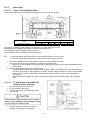
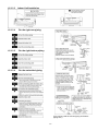
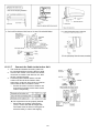
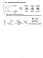
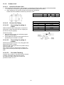
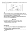
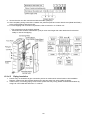
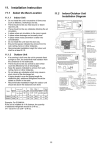
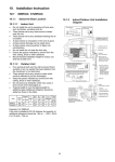
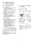
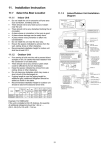
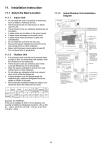
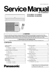
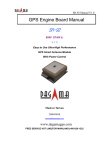
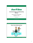
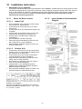
10. Installation Instruction
•
IMPORTANT (only for S18NKUA)
This product has been designed and manufactured to meet ENERGY STAR® criteria for energy efficiency when
matched with appropriate coil components. However, proper refrigerant charge and proper air flow are critical to
archive rated capacity and efficiency. Installation of this product should follow the manufacturer’s refrigerant
charging and air flow instructions. Failure to confirm proper charge and airflow may reduce energy
efficiency and shorten equipment life.
10.1.1
10.1.1.1
•
•
•
•
•
•
•
•
•
•
•
•
•
•
10.1.2
Indoor Unit
Do not install the unit in excessive oil fume areas
such as kitchens, workshops etc.
There should not be any heat source or steam
near the unit.
There should not be any obstacles blocking the air
circulation.
A place where air circulation in the room is good.
A place where drainage can be easily done.
A place where noise prevention is taken into
consideration.
Do not install the unit near a doorway.
Ensure the spaces indicated by arrows from the
wall, ceiling, fence or other obstacles.
Recommended installation height for indoor unit
shall be at least 8.2 ft.
10.1.1.2
•
Select the Best Location
Outdoor Unit
If an awning is built over the unit to prevent direct
sunlight or rain, be careful that heat radiation from
the condenser is not obstructed.
There should not be any animal or plant which
could be affected by hot air discharged.
Keep the spaces indicated by arrows from wall,
ceiling, fence or other obstacles.
Do not place any obstacles which may cause a
short circuit of the discharged air.
If piping length is over the [piping length for
additional gas], additional refrigerant should be
added as shown in the table.
Recommended installation height for outdoor unit
should be above the seasonal snow level.
Example: For S18NKUA
If the unit is installed at 41 ft distance, the quantity of
additional refrigerant should be 2.46 oz .... (41 - 32.8)
ft × 0.3 oz/ft = 2.46 oz.
19
Indoor/Outdoor Unit Installation
Diagram
10.1.3
Indoor Unit
10.1.3.1
How to Fix Installation Plate
The mounting wall must be strong and solid enough to prevent if from the vibration.
Model
S18NKUA, S24NKUA
1
○
23 1/32”
2
○
3 7/32”
Dimension
3
4
○
○
6 1/2”
6 7/32”
5
○
6 21/32”
6
○
8 5/8”
The centre of installation plate should be at more than c at right and left of the wall.
The distance from installation plate edge to ceiling should more than d.
From installation plate left edge to unit’s left side is e.
From installation plate right edge to unit’s right side is f.
B
○
: For left side piping, piping connection for liquid should be about g from this line.
: For left side piping, piping connection for gas should be about h from this line.
1
2
Mount the installation plate on the wall with 5 screws or more (at least 5 screws).
(If mounting the unit on the concrete wall, consider using anchor bolts.)
o Always mount the installation plate horizontally by aligning the marking-off line with the thread and using
a level gauge.
Drill the piping plate hole with ø2 ¾” hole-core drill.
o Line according to the left and right side of the installation plate. The meeting point of the extended line is
the center of the hole. Another method is by putting measuring tape at position as shown in the diagram
above. The hole center is obtained by measuring the distance namely 5 1/16” for left and right hole
respectively.
o Drill the piping hole at either the right or the left and the hole should be slightly slanting to the outdoor
side.
10.1.3.2
To Drill a Hole in the Wall and
Install a Sleeve of Piping
1
2
3
Insert the piping sleeve to the hole.
Fix the bushing to the sleeve.
Cut the sleeve until it extrudes about 19/32”
from the wall.
4
Finish by sealing the sleeve with putty or
caulking compound at the final stage.
20
10.1.3.3
Indoor Unit Installation
10.1.3.4
For the right rear piping
10.1.3.5
For the right bottom piping
10.1.3.6
For the embedded piping
(This can be used for left rear piping and bottom
piping also.)
21
10.1.3.7
Connect the Cable to the Indoor Unit
1. The inside and outside connecting cable can
be connected without removing the front grille.
2. Unscrew the conduit cover and fix the conduit
connector to conduit cover with lock nut, then
secure it against chassis.
3. Connecting wire between indoor unit and
outdoor unit should be UL listed or CSA
approved 4 conductor wires minimum AWG16
in accordance with local electric codes.
o Ensure the colour of wires of outdoor unit
and terminal number are the same as the
indoor's respectively.
o
This equipment must be properly earthed.
Earth lead wire shall be Yellow/Green
(Y/G) in colour and shall be longer than
other lead wires as shown in the figure for
electrical safety in case of the slipping.
22
10.1.3.8
10.1.3.9
1
2
3
Wire Stripping and connecting requirement
Cutting and flaring the piping
Please cut using pipe cutter and then remove the burrs.
Remove the burrs by using reamer. If burrs is not removed, gas leakage may be caused. Turn the piping end
down to avoid the metal powder entering the pipe.
Please make flare after inserting the flare nut onto the copper pipes.
23
10.1.4
Outdoor Unit
10.1.4.1
•
Install the Outdoor Unit
After selecting the best location, start installation to INDOOR/OUTDOOR UNIT INSTALLATION DIAGRAM.
1 Fix the unit on concrete or rigid frame firmly and horizontally by bolt nut (ø13/32”).
2 When installing at roof, please consider strong wind and earthquake.
Please fasten the installation stand firmly with bolt or nails.
Model
S18NKUA, S24NKUA
10.1.4.2
10.1.4.2.1
Piping size
1/4”
3/8”
1/2”
5/8”
3/4”
Connecting the piping to
indoor
Connect the piping
• Align the center of piping and sufficiently tighten
the flare nut with fingers.
• Further tighten the flare nut with torque wrench in
specified torque as stated in the table.
Connecting the piping to
outdoor
Decide piping length and then cut by using pipe cutter.
Remove burrs from cut edge.
Make flare after inserting the flare nut (locate at valve)
onto the copper pipe.
Align center of piping to valve and then tighten with
torque wrench to the specified torque as stated in the
table.
10.1.4.2.3
B
5 5/32”
C
5/8”
D
14 3/16”
Do not overtighten, over tightening may cause gas leakage.
Connect the Piping
Please make flare after inserting flare nut (locate at
joint portion of tube assembly) onto the copper pipe.
(In case of using long piping)
10.1.4.2.2
A
24 1/8”
Gas Leak Checking
Pressure test to system to 400 PSIG with dry nitrogen,
in stages. Thoroughly leak check the system.
If the pressure holds, release the nitrogen and
proceed to section 10.1.4.3.
24
Torque
13.3 lbf.ft
31.0 lbf.ft
40.6 lbf.ft
47.9 lbf.ft
73.8 lbf.ft
10.1.4.3
Evacuation of the equipment
WHEN INSTALLING AN AIR CONDITIONER, BE SURE TO EVACUATE THE AIR INSIDE THE INDOOR UNIT AND
PIPES in the following procedure.
1. Connect a charging hose with a push pin to the Low side of a charging set and the service port of the 3-way
valve
2. Connect the micron gauge between vacuum pump and service port of outdoor units.
3. Turn on the power switch of the vacuum pump and make sure that connect digital micron gauge and to pull
down to a value of 500 microns.
4. To make sure micron gauge a value 500 microns and close the low side valve of the charging set and turn off
the vacuum pump.
5. Disconnect the vacuum pump house from the service port of the 3-way valve.
6. Tighten the service port caps of the 3-way valve at a torque of 13.3 Ibf.ft with a torque wrench.
7. Remove the valve caps of both of the 2-way valve and 3-way valve. Position both of the valves to “Open”
using a hexagonal wrench (5/32").
8. Mount valve caps onto the 2-way valve and the 3-way valve.
o Be sure to check for gas leakage.
10.1.4.4
Connect the Cable to the Outdoor Unit
1.
2.
3.
4.
5.
6.
Remove control board cover (Resin and Metal).
Remove particular plate.
Remove plugs.
Fix the conduit connectors to the knockout holes with lock-nuts, then secure them against the side panel.
All wires pass through conduits & particular plate’s opening hole.
Connecting wire between indoor unit and outdoor unit should be UL listed or CSA approved 4 conductor
wires minimum AWG16 in accordance with local electric codes.
7. Wire connection to the power supply (208/230V 60Hz) through circuit breaker.
o Connect the UL listed or CSA approved wires minimum AWG12 to the terminal board, and connect the
other end of the wires to ELCB / GFCI.
8. Connect the power supply cord and connecting wire between indoor unit and outdoor unit according to the
diagram below.
25
9. Secure the wire onto the control board with the holder (clamper).
10. After completing wiring connections, reattach the particular plate and control board cover (Metal and Resin)
to the original position with the screws.
11. For wire stripping and connection requirement, refer to instruction g of indoor unit.
o
10.1.4.5
This equipment must be properly earthed.
Earth lead wire shall be Yellow/Green (Y/G) in colour and longer than other lead wires for electrical
safety in case of the slipping.
Piping Insulation
1. Please carry out insulation at pipe connection portion as mentioned in Indoor/Outdoor Unit Installation
Diagram. Please wrap the insulated piping end to prevent water from going inside the piping.
2. If drain hose or connecting piping is in the room (where dew may form), please increase the insulation by
using POLY-E FOAM with thickness ¼” or above.
26