1
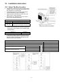
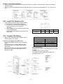
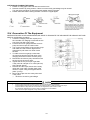
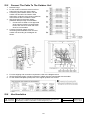
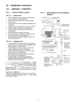
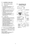
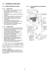
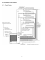
9. Installation Information 9.1 Check Points 16 10. Installation Instruction 10.1 Select The Best Location If an awning is built over the unit to prevent direct sunlight or rain, be careful that heat radiation from the condenser is not obstructed. There should not be any animal or plant which could be affected by hot air discharged. Keep the spaces indicated by arrows from wall, ceiling, fence or other obstacles. Do not place any obstacles which may cause a short circuit of the discharged air. Refrigerant piping size Outdoor Unit CU-5E36*** Liquid - side ø1/4" (ø6.35 mm) thickness 1/32" (t0.8 mm) Gas - side ø3/8" (ø9.52 mm) thickness 1/32" (t0.8 mm) *(ø1/2" (ø12.7 mm) thickness 1/32" (t0.8 mm)) * In case of indoor is CS-E24***, then ø1/2" (ø12.7 mm) thickness 1/32" (t0.8 mm) gas-pipe size must be used together with CZ-MA2P (pipe size expander) Outdoor Unit CU-5E36*** Min. total piping length for additional gas 147.6 ft (45 m) If total piping length of all indoor units exceeds the minimum length listed above, additionally charge with 0.2 oz (20g) of refrigerant (R410A) for each additional feet (meter) of piping. Allowable piping length Outdoor Unit CU-5E36*** Allowable piping length of each indoor unit (min. ~ max.) 9.8 ft ~ 82.0 ft (3 m ~ 25 m) Allowable total piping length of all indoor unit Height difference between indoor and outdoor unit Height difference between indoor unit 262.4 ft (80 m) or less Outdoor unit located on upper side 49.2 ft (15 m) or less Outdoor unit located otherwise 24.6 ft (7.5 m) or less Outdoor unit located on upper side 24.6 ft (7.5 m) or less Outdoor unit located otherwise 49.2 ft (15 m) or less 17 Outdoor Unit Installation Guidelines Where a wall or other obstacle is in the path of outdoor unit’s intake or exhaust airflow, follow the installation guidelines below. For any of the below installation patterns, the wall height on the exhaust side should be 47-1/4" (1200 mm) or less. 10.2 Install The Outdoor Unit After selecting the best location, start installation to Indoor/Outdoor Unit Installation Diagram. 1. Fix the unit on concrete or rigid frame firmly and horizontally by bolt nut (ø13/32" (ø10 mm)). 2. When installing at roof, please consider strong wind and earthquake. Please fasten the installation stand firmly with bolt or nails. Model CU-5E36*** A B C D 24-13/32" 6-11/16" 25/32" 14-31/32" (620 mm) (170 mm) (20 mm) (380.5 mm) 10.3 Connect The Piping Remove the cabinet side plate (metal) from the unit by loosening six screws. Do not over tighten, over tightening may cause gas leakage Connecting The Piping To Outdoor Unit Decide piping length and then cut by using pipe cutter. Remove burrs from cut edge. Make flare after inserting the flare nut (locate at valve) onto the copper pipe. Align center of piping to valves and then tighten with torque wrench to the specified torque as stated in the table. Piping size Torque 1/4" [6.35 mm] [18 N•m (1.8 kgf.m)] 3/8" [9.52 mm] [42 N•m (4.3 kgf.m)] 1/2" [12.7 mm] [55 N•m (5.6 kgf.m)] 5/8" [15.88 mm] [65 N•m (6.6 kgf.m)] 3/4" [19.05 mm] [100 N•m (10.2 kgf.m)] Gas Leak Checking Pressure test to system to 400 PSIG with dry nitrogen, in stages. Thoroughly leak check the system. If the pressure holds, release the nitrogen and proceed to section 10.4. 18 CUTTING AND FLARING THE PIPING 1. Please cut using pipe cutter and then remove the burrs. 2. Remove the burrs by using reamer. If burrs is not removed, gas leakage may be caused. Turn the piping end down to avoid the metal powder entering the pipe. 3. Please make flare after inserting the flare nut onto the copper pipes. 10.4 Evacuation Of The Equipment WHEN INSTALLING AN AIR CONDITIONER, BE SURE TO EVACUATE THE AIR INSIDE THE INDOOR UNIT AND PIPES in the following procedure. 1. Connect a charging hose with a push pin to the Low side of a charging set and the service port of the gas side 3-way valve. 2. Connect the micron gauge between vacuum pump and service port of outdoor units. 3. Turn on the power switch of the vacuum pump and make sure that connect digital micron gauge and to pull down to a value of 500 microns. 4. To make sure micron gauge a value 500 microns and close the low side valve of the charging set and turn off the vacuum pump. 5. Disconnect the vacuum pump house from the service port of the 3-way valve. 6. Tighten the service port caps of gas side 3-way valve at a torque of 13.3 Ibf.ft (18 N•m) with a torque wrench. 7. Remove the valve caps of both of the 2-way valve and 3-way valve. Position both of the valves to “Open” using a hexagonal wrench (5/32" (4 mm)). 8. Mount valve caps onto the 2-way valve and 3-way valve. o Be sure to check for gas leakage. - If micron gauge value does not descend 500 microns, take the following measures: If the leak stops when the piping connections are tightened further, continue working from step . If the leak does not stop when the connections are retightened, repair location of leak. Do not release refrigerant during piping work for installation and reinstallation. Take care of the liquid refrigerant, it may cause frostbite. 19 10.5 Connect The Cable To The Outdoor Unit 1. Remove Plugs. 2. Fix the conduit connectors to the knock out holes with lock-nuts, then secure them. 3. Connecting wire between indoor unit and outdoor unit should be UL listed or CSA approved 4 conductor wires minimum AWG16 in accordance with local electric codes. 4. Wire Connection to the power supply (208/230V 60Hz) through circuit breaker. o Connect the UL listed or CSA approved wires minimum AWG12 to the terminal board, and connect to other end of the wires to circuit breaker. 5. Connect the power supply cord and connecting wires between indoor unit and outdoor unit according to the diagram as shown. 6. For wire stripping and connection requirement, refer to the diagram below. 7. Secure the power supply cord and connection cables onto the control board with the holder. 8. Fix the cabinet side plate (metal) back to the original position with screws. 10.6 Heat Insulation Use a material with good heat-resistant properties as the heat insulation for the pipes. Be sure to insulate both the gas-side and liquid-side pipes. If the pipes are not adequately insulated, condensation or water leakages may occur. 20 Liquid-side pipes Material shall withstand 248°F Gas-side pipes (120°C) or higher 10.7 Disposal Of Outdoor Unit Drain Water If a drain elbow is used, the unit should be placed on a stand which is taller than 1-31/32" (50 mm). If the unit is used in an area where temperature falls below 32°F (0°C) for 2 or 3 days in succession, it is recommended not to use a drain elbow, for the drain water freezes and the fan will not rotate. 21