1
Operating Instructions
Intelligent Controller
Model No. CZ-256ESMC1U
Before operating the unit, read these operating instructions thoroughly and keep them for future reference.
85464609160011
CZ-256ESMC1U_改.indb 1
1006 Kadoma, Kadoma City, Osaka, Japan
CV6233189666
2011/11/11 11:24:52
CZ-256ESMC1U
INTELLIGENT CONTROLLER
Operating Instructions
CZ-256ESMC1U_改.indb 2
2011/11/11 11:24:54
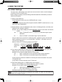
CONTENTS
1 IMPORTANT SAFETY INSTRUCTIONS ...................................................................................4
2 FEATURES OF THE SYSTEM ..................................................................................................8
3 SYSTEM CONFIGURATION......................................................................................................9
4 NAMES AND FUNCTIONS OF PARTS ...................................................................................10
5 QUICK REFERENCE ...............................................................................................................13
6 USING THE SYSTEM ..............................................................................................................15
6.1 Powering the System On..................................................................................................15
6.2 Names and Functions of Screen Parts.............................................................................15
6.2.1 Initial communications screen ..................................................................................15
6.2.2 Operating screen example .......................................................................................16
6.3 Initial Settings ...................................................................................................................18
6.3.1 System setting flow ..................................................................................................19
6.3.2 Setting the date, cut-off date, and distribution ratio calculation method ...................22
6.3.3 Setting central addresses, unit names and tenant numbers ....................................24
6.3.4 Setting tenant names and distribution groups ..........................................................26
6.3.5 Making pulse meter settings.....................................................................................28
6.3.6 Clear accumulation data...........................................................................................30
6.4 Status Monitoring and Operation Screens .......................................................................31
6.4.1 Displaying general information by tenant .................................................................31
6.4.1.1 Operating units individually..........................................................................32
6.4.1.2 Operating all units by tenant ........................................................................33
6.4.1.3 Operating all connected units ......................................................................34
6.4.2 Displaying detailed information by tenant.................................................................35
6.4.3 Displaying general information by zone ...................................................................36
6.4.4 Displaying detailed information by zone ...................................................................37
6.4.5 Displaying and operating all indoor units .................................................................38
6.5 Total Data and Manual Cut-Off Processing ......................................................................39
6.5.1 Displaying total data by indoor unit ..........................................................................39
6.5.2 Displaying total data by tenant .................................................................................40
6.5.3 Displaying total data by outdoor unit ........................................................................41
6.5.4 Displaying pulse meter total data .............................................................................42
6.5.5 Performing manual cut-off processing and saving data ...........................................43
6.5.5.1 Manual cut-off processing ...........................................................................43
6.5.5.2 Saving data..................................................................................................44
6.5.5.3 Outputting distribution data in progress .......................................................44
6.5.5.4 Restoring data .............................................................................................45
6.6 Air Conditioning Distribution Ratios and Energy Usage ...................................................46
6.6.1 Displaying distribution ratios and energy usage by indoor unit ................................46
6.6.2 Displaying distribution ratios and energy usage by tenant .......................................47
6.6.3 Time zone totals and distribution ..............................................................................48
6.7 Maintenance and Test Runs .............................................................................................49
6.7.1 Checking inspection signs ........................................................................................49
6.7.2 Checking the alarm logs ...........................................................................................50
6.7.3 Executing test runs ...................................................................................................52
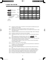
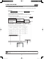
5 Sub1
5
Main Sub2
Main5 Sub3
Main5 Sub 4
Main5 Sub5
Main
1 Sub1
Main
1 Sub 2
1 Sub 3
Main1 Sub 4
Main1 Sub 5
Main
Main
2 Sub1
Main 2 Sub2
Main 2 Sub3
Main 2 Sub 4
Main 2 Sub5
Main
3 Sub1
Main3 Sub2
Main
4 Sub1
Main4 Sub 2
Main4 Sub 3
Main
5 Sub1 refers to the explanation of main menu 5, sub menu 1.
Main
2
CZ-256ESMC1U_改.indb 2
2011/11/11 11:24:54
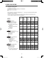
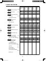
6.8 Auxiliary Settings ..............................................................................................................53
6.8.1 Registering zone names...........................................................................................53
6.8.2 Setting zone numbers and management targets .....................................................54
6.8.3 Programming timers .................................................................................................56
6.8.3.1 Programming daily timers ............................................................................56
6.8.3.2 Programming weekly timers ........................................................................59
6.8.4 Setting Tenant holiday/Timer special day .................................................................60
6.8.5 Prohibiting remote control use..................................................................................61
6.8.6 Setting distribution time zones .................................................................................62
6.8.7 Setting special distribution days ...............................................................................63
6.8.8 Indoor unit settings ...................................................................................................64
6.8.9 Other settings ...........................................................................................................65
6.8.9.1 Checking the connection configuration........................................................65
6.8.9.2 Registering passwords ................................................................................66
6.8.9.3 Selecting no-communications mode............................................................66
6.8.9.4 Buzzer sounds .............................................................................................66
6.8.9.5 Initialization ..................................................................................................66
6.8.9.6 LCD auto off settings ...................................................................................67
6.8.9.7 Calibrating touch panels ..............................................................................67
6.8.9.8 Power off button ..........................................................................................68
6.8.10 WEB settings ..........................................................................................................69
6.8.10.1 Detailed server settings .............................................................................70
6.8.10.1.1 Receiving server settings .........................................................71
6.8.11 User settings...........................................................................................................72
6.9 System Configuration Changes........................................................................................74
6.9.1 When a system configuration change detected .......................................................74
6.9.2 When system configuration may change .................................................................75
7 ENTERING TEXT AND NUMBERS .........................................................................................76
7.1 Entering Numbers ............................................................................................................76
7.2 Entering Text ....................................................................................................................77
8 CONNECTION OF EXTERNAL SIGNALS ..............................................................................79
8.1 Pulse Meter Input .............................................................................................................79
8.2 All Stop Input ....................................................................................................................80
8.3 All Start Input ....................................................................................................................80
8.4 All-Unit Alarm Output ........................................................................................................81
8.5 All-Unit Operation Output .................................................................................................81
9 TERMS .....................................................................................................................................82
10 CALCULATING AIR CONDITIONER DISTRIBUTION ..........................................................83
10.1 Calculating simple distribution ........................................................................................83
10.2 Calculating air conditioner energy usage .......................................................................85
10.3 Calculating loaded distribution .......................................................................................86
11 SUPPLEMENTARY INFORMATION-1 ...................................................................................87
12 SUPPLEMENTARY INFORMATION-2 ..................................................................................88
13 TROUBLESHOOTING ...........................................................................................................91
14 MAINTENANCE .....................................................................................................................93
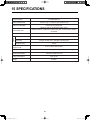
15 SPECIFICATIONS..................................................................................................................94
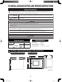
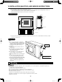
16 INSTALLATION (ELECTRIC) AND SERVICE INSTRUCTIONS ...........................................96
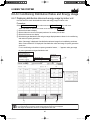
6 Sub1
Main6 Sub2
Main6 Sub3
Main
6 Sub4
Main6 Sub5
Main6 Sub6
Main6 Sub7
Main6 Sub8
Main6 Sub9
Main
6 Sub10
Main
6 Sub11
Main
3
CZ-256ESMC1U_改.indb 3
2011/11/11 11:24:55
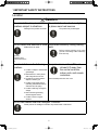
1 IMPORTANT SAFETY INSTRUCTIONS
Before using the system, be sure to read these “Important Safety
Instructions”.
The precautions given in this manual consist of specific
“ Warnings” and “ Cautions”. They provide important safety
related information and are important for your safety, the safety of
others, and trouble-free operation of the system. Be sure to strictly
observe all safety procedures.
● The labels and their meanings are as described below.
Warning
Caution
This refers to a hazard or unsafe procedure or practice which can result in
severe personal injury or death.
This refers to a hazard or unsafe procedure or practice which can result in
personal injury or product or property damage.
● Meaning of symbols
Indicates “Warning” or “Caution”.
Indicates “Prohibited”.
Indicates an action that should always be performed.
● After reading this manual, save it in a convenient place.
Be sure to provide this manual to any person who may use the product.
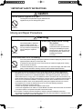
Installation Precautions
Warning
Do not install yourself
Have dealer
install
Use only specified air conditioners
Installation should always be
performed by your dealer or a
professional service provider.
Electric shock or fire may result
if an inexperienced person
performs any installation or wiring Specified air
conditioners
procedures incorrectly.
Always use only air conditions
specified by the dealer.
Electrical work must be carried out by qualified personnel
Contact your dealer for installation. Do not attempt to install the product yourself.
4
CZ-256ESMC1U_改.indb 4
2011/11/11 11:24:57
1 IMPORTANT SAFETY INSTRUCTIONS
Location
Caution
Do not install in damp locations or
locations subject to vibrations
Do not install under direct sunlight or
in places near heat sources
Damage to the product can result.
The product may be damaged.
Do not install near sources of noise Avoid static electricity during cabling
Malfunctions can result.
work
Before starting cabling work, touch
ground to discharge static electricity
from the body.
Elevators,
Automatic doors,
Industrial machinery,
etc
Avoid installation in the following
locations
Keep televisions, radios, PCs, etc,
at least 4 ft away from
the central controller,
indoor units, and remote
controllers.
● Locations subject to inflammable
gas leakage
● Near beaches or other places
with a large amount of salt
Picture breakup and noise can occur.
● Hot springs or other locations
subject to sulfuric gas
● Locations near water and oil
(including industrial lubricants),
and water and oil sprays
● Locations with large changes in
voltage
● Near machines generating
electromagnetic waves
● Locations close to organic
solvents
Do not use heaters near the Intelligent Controller
Plastic parts of the Intelligent Controller may be deformed or discolored.
5
CZ-256ESMC1U_改.indb 5
2011/11/11 11:24:58
1 IMPORTANT SAFETY INSTRUCTIONS
Precautions for Use
Warning
Do not touch switches with wet
hands
Protect the Intelligent Controller from
water
Electric shock and damage to the
system can result.
Damage to the system can result.
Prohibited
Prohibited
Stop the system and turn the power off if you sense unusual smells or
other irregularities
Turn off
the power.
Continuing operation when the system is
out of order can result in electric shock, fire,
and damage to the system.
Contact your dealer
Caution
Do not drop the system or subject
it to strong shocks
Use only fuses with the correct
capacity
Damage to the system can result.
Use of pins or copper wire can result in
fire and damage to the
system.
Prohibited
Prohibited
Use only the specified power source
Use of any other power source can
result in fire and damage to the
system.Use single-phase 100-240V
power.
6
CZ-256ESMC1U_改.indb 6
2011/11/11 11:24:58
1 IMPORTANT SAFETY INSTRUCTIONS
Caution
Use the special supplied touch pen
Touching the touch panel with any pen other than the
supplied touch pen can damage the system.
Prohibited
Moving and Repair Precautions
Warning
Do not disassemble or repair
Never disassemble or repair the
system yourself. Contact your
dealer for repair. Electric shock or
fire may result if an inexperienced
person attempts to repair the
system.
Contact your dealer before moving
the system
Contact
your dealer
Prohibited
Contact your dealer or a
professional service provider about
moving and reinstalling the system.
Electric shock or fire may result if an
inexperienced person performs any
installation procedures
incorrectly.
Do not touch the LCD if it is leaking
Prohibited
If the touch panel is damaged, the liquid crystal from inside the display may leak out. Do not
ingest the liquid or allow it to contact your skin.
If accidental contact with skin occurs, rinse the area of contact thoroughly under running
water for at least 15 minutes.
If accidental swallowing occurs, rinse the inside of your mouth thoroughly with water. Drink
plenty of water and induce vomiting, and then seek immediate medical attention.
Note: ●This equipment has been tested and found to comply with the limits for a Class B digital device,
pursuant to part 15 of the FCC Rules. These limits are designed to provide reasonable protection
against harmful interference in a residential installation. This equipment generates, uses and can
radiate radio frequency energy and, if not installed and used in accordance with the instructions,may
cause harmful interference to radio communications. However, there is no guarantee that interference
will not occur in a particular installation. If this equipment does cause harmful interference to radio
or television reception, which can be determined by turning the equipment off and on, the user is
encouraged to try to correct the interference by one or more of the following measures:
• Reorient or relocate the receiving antenna.
• Increase the separation between the equipment and receiver.
• Connect the equipment into an outlet on a circuit different from that to which the receiver is connected.
• Consult the dealer or an experienced radio/TV technician for help.
●FCC Caution: To assure continued compliance, follow thw attached installation instructions.
Any changes or modifications not expressly approved by the party responsible for compliance could
void the user’s authority to operate this equipment.
7
CZ-256ESMC1U_改.indb 7
2011/11/11 11:24:59
2 FEATURES OF THE SYSTEM
The Intelligent Controller is a centralized air conditioning management system dedicated to PAC and GHP for
small and medium sized buildings.
● Number of connectable units ········ • By connecting communication adaptors to one Intelligent Controller, up
to 256 indoor units can be connected.
• Up to 120 outdoor units can be connected.
● Display ·········································· • Touch panel type 6.5-inch TFT color (640x480 pixel VGA) LCD
display
● Operation functions······················· • Start and stop, temperature settings, operation mode selection, fan
speed settings, fan direction settings, ventilation etc.
● Operating monitoring ···················· • All unit monitoring of operation status (operating/stopped, operation
mode, alarms)
• Display of alarm logs
• One-operation checking of all filter cleaning signs and engine oil
inspection signs
• External output of all errors, external output of all operations (relay
connections)
● Program timers …………………… • Up to 50 types of weekly timers can be programmed by combining
50 types of daily timers (50 times per day).
● Air conditioning energy
distribution ····································· • Recording and display of accumulated operating time and total number
of operations for each indoor unit.
• Calculation of gas and electricity distribution ratios and energy amounts
used (m3, kWh) for each indoor unit and each tenant.
• Distributions are available in two modes: the “simple distribution”
calculated based on the operating time and “loaded distribution”
calculated based on the actual air conditioning capacity, respectively.
(In order to make operation in the “Loaded distribution” mode, the air
conditioner side needs to be adaptable to the “Loaded distribution”.
• Distribution by time zones (regular hours, out of hours, special days).
• Recording of up to past 24 months of cut-off data.
Terms and abbreviations used in this manual and in the system software
Full term
Abbreviation
Adaptor address
Adaptor
Link system address
Link system
Outdoor unit system address
Outdoor unit system, Outdoor unit, Outdoor system, Outdoor, O/D
Indoor unit address
Indoor unit, Indoor, I/D
Distribution group number
Distribution group No., Distribution group
Tenant number
Tenant No., Tenant
Zone number
Zone No., Zone
Unit name
Unit
Air conditioning distribution ratio
Distribution ratio, Distr. ratio
Central control address
Central address, CNTR
Thermostat
T/S
* For more information about terms, see “9 Terms”.
8
CZ-256ESMC1U_改.indb 8
2011/11/11 11:24:59
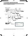
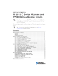
3 SYSTEM CONFIGURATION
System Configuration Example
Intelligent Controller
Indoor/outdoor control wire Link system
(non-polar)
No.1
Link system
No.2
Pulse meter x 3
All-unit signal x 4
Indoor/outdoor
control wire
(non-polar)
Communication adaptor
control wire
Communication adaptor
(RS-485, polar)
Link system
No.3
Pulse meter x 3
All-unit signal x 4
Link system
No.4
Communication adaptor
G
W
Pulse meter
G: Gas flow meter
W: Electricity meter
All-unit signal x 4
Independent installation
without link system
connection also possible
Maximum number of connections
Indoor units:
Outdoor units:
Communication adaptors:
Link systems:
(Indoor/outdoor control wires)
256 (64/link x 4)
120 (30/link x 4)
7
4
* When connecting link systems (inter-unit control wires), always connect beginning with LINK1 and LINK2 on
the Intelligent Controller. Up to 4 link systems can be connected.
9
CZ-256ESMC1U_改.indb 9
2011/11/11 11:25:00
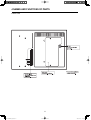
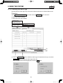
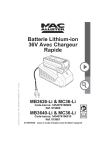
4 NAMES AND FUNCTIONS OF PARTS
● Front Panel
Touch panel type color LCD display
Displays operating screens. Use
the supplied touch pen to operate.
Power indicator
lights to show that the intelligent
controller is powered on.
POWER
Touch pen
Used to carry out
operations on the
LCD display.
PC Card and touch pen
storage cover
Push the cover to open it. The
compartment inside is used to
store the touch pen and to
insert and eject PC Cards for
backup.
PC Card socket
Used to insert optional
PC Cards for backup.
10
CZ-256ESMC1U_改.indb 10
2011/11/11 11:25:00
4 NAMES AND FUNCTIONS OF PARTS
● Rear Panel
11
CZ-256ESMC1U_改.indb 11
2011/11/11 11:25:01
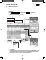
4 NAMES AND FUNCTIONS OF PARTS
● Right side panel
Power connector panel
AC100V-240V power
connector panel.
Power switch
Powers the Intelligent Controller
on and off.
OFF
ON
Communications connector panel
1
2
3 U1
4 U2
5 U1
6 U2
ADAPT Connect to
(RS-485) communication
adaptor.
LINK1
Indoor/outdoor
control wire 1
LINK2
Indoor/outdoor
control wire 2
7 DO-COMM
8 DO 1
All alarm output
9 DO 2
All operation
output
10 DI-COMM
11 DI 1
All stop input
12 DI 2
All start input
12
CZ-256ESMC1U_改.indb 12
2011/11/11 11:25:01
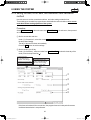
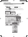
5 QUICK REFERENCE
Menu List
Sub Menu
1. Status/Control
1.Each tenant
2.Each tenant details
3.Each zone
4.Each zone details
C
5.All units
➢page 31
➢page 35
➢page 36
➢page 37
➢page 38
2. Total data/Cut-off
1.Each I/D unit
2.Each tenant
B 3.Each O/D unit
4.Pulse meter
A 5.Cut-off/Data backup
➢page 39
➢page 40
➢page 41
➢page 42
➢page 43
3. Distrib. ratio/Usage
1.Each I/D unit
2.Each tenant
B
Main Menu
1.Status/Control
2.Total data/Cut-off
3.Distrib. ratio/Usage
4.Maintenance/Test Run
5.Initial settings
6.Auxiliary settings
➢page 46
➢page 47
4. Maintenance/Test Run
1.Inspection sign
2.Alarm log
A 3.Test run
➢page 49
➢page 50
➢page 52
1.Date/Distrib.
2.CNTR/Unit/Ten. No.
A 3.Ten. name/Distrib. Gr.
4.Pulse meter setting
5.Clear accum. data
➢page 22
➢page 24
➢page 26
➢page 28
➢page 30
5. Initial settings
Start the Initial settings first.
6. Auxiliary settings
shows screens protected using
“Setting” password.
A
1.Zone name
2.ZoneNo./Mng.target
3.Program timer
4.Ten.Ho/TimerSp.Day
5.Prohibit R/C
6.Distribution time zone
7.Special distrib. day
8.I/D unit settings
9.Other settings
A 10.WEB settings
11.User settings
shows screens protected using
“Distribution” password.
B
C
shows screens protected using
“Operation” password. (Only the
soft-remote controller is protected.
The status is visible.)
➢page 53
➢page 54
➢page 56
➢page 60
➢page 61
➢page 62
➢page 63
➢page 64
➢page 65
➢page 69
➢page 72
13
CZ-256ESMC1U_改.indb 13
2011/11/11 11:25:01
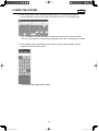
5 QUICK REFERENCE
Menu List
Listed are only typical functions.
How to operate air conditioners
Operating all units collectively desired
Operating units individually desired
Operating units by tenant desired
Operating units by zone desired
Varying operation modes desired
Varying setting temperatures desired
Resetting filter signs desired
Varying fan direction and speed
Prohibiting remote controlling desired
→ 6.4.1.3 Operating all connected units
→ 6.4.1.1 Operating units individually
→ 6.4.1 Displaying general information by tenant
→ 6.4.3 Displaying general information by zone
→ 6.4.1.1 Operating units individually
→ 6.4.1.1 Operating units individually
→ 6.4.1.1 Operating units individually
→ 6.4.1.1 Operating units individually
→ 6.4.1.1 Operating units individually
Page 34
Page 32
Page 31
Page 36
Page 32
Page 32
Page 32
Page 32
Page 32
Monitoring status of air conditioner operation
Monitoring status of inspection signs desired
Monitoring operation status collectively desired
Checking the alarm history desired
Checking current and past total calculation
times desired
Checking current and past distribution ratios
and energy consumption desired
→ 6.7.1 Checking inspection signs
→ 6.4.5 Displaying and operating all indoor units
→ 6.7.2 Checking the alarm logs
→ 6.5.1 Displaying total data by indoor unit
Page 49
Page 38
Page 50
Page 39
→ 6.6.1 Displaying distribution ratios and energy
usage by indoor unit
Page 46
→ 6.3.3 Setting central addresses, unit names
and tenant numbers
→ 6.3.4 Setting tenant names and distribution
groups
→ 6.8.1 Registering zone names
→ 6.3.2 Setting the date, cut-off date,
and distribution ratio calculation method
→ 6.3.5 Making pulse meter settings
Page 24
Setting the system
Changing the unit names desired
Changing tenant names desired
Changing zone names desired
Adjusting dates and times desired
Changing type of pulse meter
(power meter or gas meter)
Setting timer operation desired
→ 6.8.3 Programming timers
Setting security displayed on the screen desired → 6.8.9.2 Registering passwords
Stopping or sounding the buzzer
→ 6.8.9.4 Buzzer sounds
Page 26
Page 53
Page 22
Page 28
Page 56
Page 66
Page 66
Others
Backing up PC cards desired
Powering off Intelligent Controllers desired
Outputting distribution in progress desired
Calibrating touch panel deviations
→ 6.5.5.4 Restoring data
→ 6.8.9.8 Power off button
→ 6.5.5.3 Outputting distribution data in progress
→ 6.8.9.7 Calibrating touch panels
Page 45
Page 68
Page 44
Page 67
14
CZ-256ESMC1U_改.indb 14
2011/11/11 11:25:02
6 USING THE SYSTEM
6.1 Powering the System On
Check the wiring, (air conditioners, communication adaptors, etc.) and then turn the power switch
on (see page 12). The system starts automatically.
When the system is powered on for the first time, about 10 minutes are required for the normal
system screen to appear. Wait until it appears.
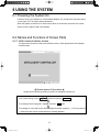
6.2 Names and Functions of Screen Parts
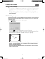
6.2.1 Initial communications screen
The figure below shows the initial communications screen, which appears when the Intelligent
Controller starts.
(WED) 23/Aug 1:21PM
System power off procedure
Always use the following procedure to power the Intelligent Controller off.
In the “Other settings” menu ( Main6 Sub9 ), select the last item, Power off .
The message “Exit this program?” appears. Press the OK button.
The message “It is now safe to turn off the Intelligent Controller.” appears ( ∗ ). Turn the power off.
( ∗ Several minutes may be required before the message appears.)
15
CZ-256ESMC1U_改.indb 15
2011/11/11 11:25:02
6 USING THE SYSTEM
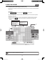
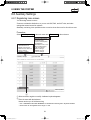
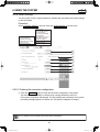
6.2.2 Operating screen example
The figure below shows a typical operating screen.
Filter cleaning sign
Main menu
This lights when a filter
cleaning sign has been
issued for an indoor unit.
Sub menu
1.Status/Control
2.Total data/Cut-off
3.Distrib. ratio/Usage
4.Maintenance/Test Run
5.Initial settings
6.Auxiliary settings
Operate on all
units
Displays tenant
name.
Displays unit
name.
Timer
operation
mark
Scrolls the
columns
displaying indoor
units.
This lights
when an
indoor unit
is set up
for timer
operation.
(FRI) 4/Aug 2:56PM
Tenant selection window
Scrolls the display of
tenants.
Allows direct selection of
tenant names.
* See next page for details.
Displays the current date and time.
Reset button
Stops the buzzer and resets
the alarm display. (Depends on
the type of alarm.)
Notification column
Displays alarms, errors, and other messages.
Intelligent Controller – 1 – 01 – 08
Indoor address (1-64)
Outdoor address (1-30)
Link number (1,2)
Adaptor number (Intelligent Controller, 1-7)
Filter cleaning signs are issued only as approximate guides. We recommend that filters be cleaned
regularly, even if no sign has been issued.
16
CZ-256ESMC1U_改.indb 16
2011/11/11 11:25:04
6 USING THE SYSTEM
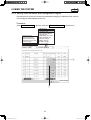
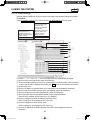
* Selection windows
When you touch [Tenant] (or whatever is displayed in blue between the scroll buttons) shown on the
previous page, the items available for selection appear in a list as follows, enabling direct selection.
[Tenant] list
(FRI) 4/Aug 2:56PM
A similar list appears for the other buttons.
[I/D unit] list
[Weekly timer] list
Tenant holiday [Date] list
17
CZ-256ESMC1U_改.indb 17
2011/11/11 11:25:05
6 USING THE SYSTEM
6.3 Initial Settings
The items in the “Initial settings” menu (main menu 5) must be set in order to use the Intelligent
Controller. Be sure to set these items.
Before making the settings, read the following and decide what kind of information you want to
obtain from the system.
(1) Setting central addresses
Central addresses must be set on the “CNTR/Unit/Ten.No.” screen
( Main5 Sub2 ).
Be aware that using them along with the system controller, ON/OFF-controller and so on, may
affect zone control classification.
(2) Decide whether or not to use distribution ratios. (See “6.3.2 Setting the date, cut-off date, and
distribution ratio calculation method”.)
Question: Do you need to display and record distribution ratios for each indoor unit and each
tenant?
Yes →
Select “T/S ON+OFF time” or “T/S ON time” as calculation target of power
distribution.
No →
Select “No Distrib.” as calculation target of power distribution.
If all you need to do is to monitor air conditioning status, operate the system, and view total
data for operating time and so on, you should select “ No Distrib.”. (Information you do not
need will not be displayed.)
When you select “No”, the following displays are disabled.
Setting items
Display items
Menus
5 Sub3 .
: Time zones in Main 2 Sub1 and Main 2 Sub2 .
: Main3 Sub1 and Main3 Sub2 , Main6 Sub6 , Main6 Sub7 , and Main6 Sub8
: Distribution group registration in Main
(3) If you will be using distribution ratios, decide which calculation method to use. (See “6.3.2
Setting the date, cut-off date, and distribution ratio calculation method”.)
Question: Do you need to consider electricity of indoor units?
Yes →
Select “T/S ON+OFF time” as calculation target of power distribution.
No →
Select “T/S ON time” as calculation target of power distribution.
If pulse (electricity) meters are installed for measuring both indoor and outdoor units, select
“T/S ON+OFF time”.
If only outdoor units are measured, select “T/S ON time”.
(4) Pulse meter settings (See “6.3.5 Making pulse meter settings”.)
When you need to display air conditioner distribution ratios for (1) above,
Question: Do you require monthly energy usage display?
Yes →
Install a pulse meter for each distribution group.
No →
Pulse meter installation is unnecessary.
When pulse meters are not set, “0” is displayed for usage.
You can remove connected units from management by this system. For details, see “6.8.2 Setting zone
numbers and management targets”.
18
CZ-256ESMC1U_改.indb 18
2011/11/11 11:25:06
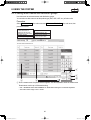
6 USING THE SYSTEM
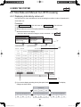
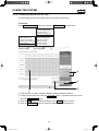
6.3.1 System setting flow
: Settings are necessary.
: Settings are necessary depending on circumstances.
: Settings are unnecessary.
Basic settings are completed by setting items of “ ” one by one in accordance with the system
management of the customer.
Items of “ ” need to be set only when making necessary settings and maintenance upon
customer request regardless of the said management.
Air
conditioner
operation
only
START
↓
5 Sub1 Date/Distrib.
Displaying
distribution
ratios
(simple
distribution)
Displaying
distribution
ratios
(loaded
distribution)
Displaying
energy
usage
(simple
distribution)
Displaying
energy
usage
(loaded
distribution)
Main
(1) Setting the current date
(2) Setting the cut-off date
(3) Calculation target of power
distribution
(4) Setting the energy saving
distribution
(5) Language
Note 1
Note 2
Note 2
↓
5 Sub2 CNTR/Unit/Ten.No.
Main
(1) Central addresses
(2) Unit name
(3) Tenant No.
Note 8
Note 3
↓
5 Sub3 Ten.name/Distrib.Gr.
Main
(1) Tenant name
(2) Distribution group
Product type
Distribution “Loaded” or
Note 14
“Simple”
↓
Note 3
Note 4
Note 5
Note 4
Note 5
5 Sub 4 Pulse meter setting
Main
(1) Pulse meter type
(2) Distribution group
(3) Pulse unit value
(4) Ice heat accumulation night
power / system selection
19
CZ-256ESMC1U_改.indb 19
2011/11/11 11:25:07
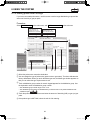
6 USING THE SYSTEM
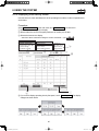
↓
5 Sub5 Clear accum.data
Main
Note 6
↓
Air
conditioner
operation
only
Displaying
distribution
ratios
(simple
distribution)
Displaying
distribution
ratios
(loaded
distribution)
Displaying
energy
usage
(simple
distribution)
Displaying
energy
usage
(loaded
distribution)
Note 1
6 Sub1 Zone name
Note 7
Main
↓
6 Sub2 ZoneNo./Mng.target
Main
(1) Zone No.
(2) Management target
↓
Note 7
6 Sub3 Program timer
Main
(1) Daily timer
(2) Weekly timer
↓
6 Sub4
Main
Ten.Ho/TimerSp.Day
↓
6 Sub5 Prohibit R/C
Main
↓
6 Sub6 Distribution time zone
Main
↓
6 Sub7 Special distrib. day
Main
↓
6 Sub8 I/D unit setting
Main
Note 9
(1) Indoor unit capacity
(2) Electric heater capacity
Note 10
↓
6 Sub9 Other settings
Main
(1) Checking system
configuration
(2) Set/Clear password
(3) No-communications mode
Note 11
(4) Buzzer
Note 12
(5) Initialization
(6) Auto display off
(7) Touch panel calibration
Note 15
(8) Power off
20
CZ-256ESMC1U_改.indb 20
2011/11/11 11:25:12
6 USING THE SYSTEM
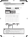
Air
conditioner
operation
only
↓
Main6 Sub10 WEB settings
Note 17
Displaying
distribution
ratios
(simple
distribution)
Displaying
distribution
ratios
(loaded
distribution)
Displaying
energy
usage
(simple
distribution)
Displaying
energy
usage
(loaded
distribution)
↓
Main6 Sub11 User settings
Note 17
↓
Main 2 Sub5 Cut-off/Data backup
(1) Manual cut-off
(2) Data backup
(3) Restore
↓
END
Note 1
Note 2
Note 3
Note 4
Note 5
Note 6
Note 6
Note 13
Note 13 and 16
Settings are necessary when you would like to monitor operation accumulated time only and
distribution ratio is not needed.
Settings are necessary only when air-conditioners include a 3-Way type unit.
Make settings even when no distribution is made, if you would like to control units as a bundle
of the group of tenants.
Settings are necessary only when the indoor unit has interface adaptor and is set at almighty.
Settings are necessary only for the indoor unit set at almighty.
Immediately before delivery, execute “Clear accum.data” to clear total data taken during test
runs.
2 5
Note 7
Note 8
Note 9
Note 10
Note 11
Note 12
Note 13
Note 14
Note 15
Note 16
Note 17
When clearing the test run data after storing it, make “Cut-off” ( Main Sub ) manually.
Make the settings when you would like to operate the unit by optional grouping.
When using the unit along with the system controller or ON/OFF-controller, the controller-side
control classification needs to be taken into consideration.
The system controller or ON/OFF-controller-side zone varies as varying central addresses
from the Intelligent Controller.
Settings are necessary only for interface adaptor.
Settings are unnecessary for the simple distribution as they will be taken into consideration in
calculation only for the loaded distribution.
Always set the mode at “NO (Normal)”.
Do not make any initialization imprudently as it may cause missing of all the set and cut-off
data.
The system works only with the backup PC card inserted, which is separately available.
Always manually make the cut-off processing in advance to vary the method of distribution.
Although the touch panel is adjusted before factory shipment, calibrate deviations if any.
Do not restore any data imprudently as it may return them to their backed-up status.
Settings are necessary when you would like to control/monitor the unit via network.
21
CZ-256ESMC1U_改.indb 21
2011/11/11 11:25:15
6 USING THE SYSTEM
5 Sub1
Main
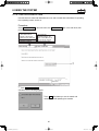
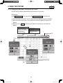
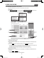
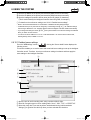
6.3.2 Setting the date, cut-off date, and distribution ratio calculation
method
Use this screen to set the current date and time, and make settings related to time.
These settings are needed for program timers and distribution ratio calculation, so be sure to
make them before starting operation of the system.
Procedure
Select 5.Initial settings in the main menu and 1.Date/Distrib. in the sub menu, then proceed
as follows.
A Set the current date and time.
Under “(1) Current time”, select the current year, month, day, hour, minute, and second from
the drop-down lists( ).
The day of the week is shown automatically.
Press the Set button to set the settings.
B Set the monthly cut-off day.
Under “(2) Cut-off day”, select a number from 1 to 28 or End (to select the last day of the
month) from the drop-down list( ).
1.Status/Control
2.Total data/Cut-off
3.Distrib. ratio/Usage
4.Maintenance/Test Run
5.Initial settings
6.Auxiliary settings
1.Date/Distrib.
2.CNTR/Unit/Ten. No.
3.Ten. name/Distrib. Gr.
4.Pulse meter setting
5.Clear accum. data
1
2
3
4
5
If the time set is ahead of the current time, the program timer set in that period becomes
invalid and transmission is not performed.
22
CZ-256ESMC1U_改.indb 22
2011/11/11 11:25:16
6 USING THE SYSTEM
5 Sub1
Main
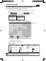
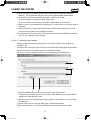
C Select the calculation target of power distribution.
(3) Select T/S ON+OFF time , T/S ON time , or No Distrib. .
- T/S ON + OFF time
To be selected when taking power both for the outdoor and indoor units to make
distribution calculation.
- T/S ON time
To be selected when taking power only for the outdoor unit to make distribution
calculation.
- No Distrib.
To be selected when distribution calculation for gas and electricity is unnecessary.
D Select the energy savings distribution settings.
(4) Select Each O/D sys. or Each Dist. Gr. .
This item cannot be selected when No Distrib. has been set for “(3) Calc. target of power
distribution”.
Select a range where the energy savings effect in 3 WAY units can be reflected on the
distribution calculation.
- Each O/D sys.
The energy savings operation in 3 WAY units is reflected only on the air conditioning
distribution for the tenant for the outdoor system.
- Each Dist.Gr.
The energy savings operation in 3 WAY units is reflected on air conditioning distributions
for all the tenants in the overall distribution group including them.
(However, this is effective only when plural distribution groups have been set.)
E In the Language pull-down menu (5), select the language you would like to use.
23
CZ-256ESMC1U_改.indb 23
2011/11/11 11:25:17
5 Sub2
6 USING THE SYSTEM
Main
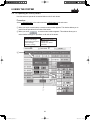
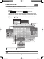
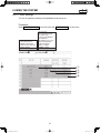
6.3.3 Setting central addresses, unit names and tenant numbers
Use this screen to set central addresses, names of units connected to the system and tenant
numbers.
Procedure
Select 5.Initial settings in the main menu and 2.CNTR/Unit/Ten. No. in the sub menu, then
proceed as follows.
1.Status/Control
2.Total data/Cut-off
3.Distrib. ratio/Usage
4.Maintenance/Test Run
5.Initial settings
6.Auxiliary settings
A
B
1.Date/Distrib.
2.CNTR/Unit/Ten. No.
3.Ten. name/Distrib. Gr.
4.Pulse meter setting
5.Clear accum. data
C
A When you touch a central address column, a screen will be displayed as shown on the right.
Input a number 1 to 64 to set central address.
When you touch [Auto], the central address will be automatically set.
Two identical central address settings cannot be used within a link system. If you input an existing
address, the input data is cancelled.
It may take several minutes before the central address settings are reflected in the display.
When other central controllers (system controller, etc.) are connected, it is recommended to set the
central addresses on those units.
24
CZ-256ESMC1U_改.indb 24
2011/11/11 11:25:17
6 USING THE SYSTEM
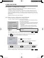
5 Sub2
Main
B Touch an unit name column. A keyboard window like the one shown below appears.
Use the keyboard to enter an unit name. Unit names can be up to 12 characters long.
* See “7 ENTERING TEXT AND NUMBERS” for details about entering text in keyboard windows.
* You can copy and paste text using the [Copy] and [Paste] buttons. See “7.2 Entering Text” for details.
C Touch a tenant number.A keyboard window like the one shown below appears. Use the
keyboard to enter the tenant number.
* The tenant number range is from 1 to 256.
25
CZ-256ESMC1U_改.indb 25
2011/11/11 11:25:18
6 USING THE SYSTEM
5 Sub3
Main
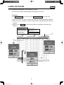
6.3.4 Setting tenant names and distribution groups
Use this screen to set tenant names and distribution groups.
You can also use this screen to set the product type (PAC, GHP, HOT, etc.) of indoor units.
Procedure
Select 5.Initial settings in the main menu and 3.Ten. name/Distrib. Gr. in the sub menu, then
proceed as follows.
1.Status/Control
2.Total data/Cut-off
3.Distrib. ratio/Usage
4.Maintenance/Test Run
5.Initial settings
6.Auxiliary settings
1.Date/Distrib.
2.CNTR/Unit/Ten. No.
3.Ten. name/Distrib. Gr.
4.Pulse meter setting
5.Clear accum. data
E
A
C
D
B
A Touch a tenant name. A keyboard window appears. Use the keyboard to enter the tenant name.
Tenant names can be up to 20 characters long.
* See “7 ENTERING TEXT AND NUMBERS” for details about entering text on software keyboards.
* The tenant number range is from 1 to 256.
26
CZ-256ESMC1U_改.indb 26
2011/11/11 11:25:18
6 USING THE SYSTEM
5 Sub3
Main
B Touch a distribution group. A keyboard window like the one shown above appears. Use the
keyboard to enter a distribution group number and to select the product type from among PAC,
GHP and HOT.
Select “Simple” or “Load” in the distribution methods.
* Refer to “10. Calculating air conditioner distribution” for details.
The tenant set at “Load” distribution will have its “No” box display in light blue.
* The distribution group number range is from 1 to 8.
5 1
* This button is invalid when “No Distrib.” has been set. (Refer to Main Sub )
* The distribution group column set at loaded distribution has no product type such as “PAC” and “GHP”
displayed.
* Make manual cut-off in advance to change the distribution method.
C Press the Type button to select “PAC” or “GHP” for the following unit that is unable to
automatically recognize product type.
- Interface adaptor
This is only for “Simple distribution” setting.
D Specify which distribution method, “Simple” or “Load,” to apply to the selected distribution
group.
E Touch Set to confirm the setting, or Cancel to cancel it.
• PAC, GHP, and HOT cannot be mixed in the same group. Set up a separate distribution group for each
type.
• HOT multi units cannot be recognized automatically (they are recognized as PAC). Manually set the
product type to HOT.
• HOT Tenants cannot be set at the “Load” distribution.
• “Load” distribution tenants cannot be set at “HOT”.
• Air conditioners unadaptable to loaded distribution cannot be set at “Load” Distribution.
• Interface adaptors are also unadaptable to loaded distribution.
27
CZ-256ESMC1U_改.indb 27
2011/11/11 11:25:19
6 USING THE SYSTEM
5 Sub 4
Main
6.3.5 Making pulse meter settings
If you have connected pulse meters, use this screen to set the target distribution groups and the
amount of electricity or gas per pulse.
Procedure
Select 5. Initial settings in the main menu, and 4. Pulse meter setting in the sub menu.
1.Status/Control
2.Total data/Cut-off
3.Distrib. ratio/Usage
4.Maintenance/Test Run
5.Initial settings
6.Auxiliary settings
1.Date/Distrib.
2.CNTR/Unit/Ten. No.
3.Ten. name/Distrib. Gr.
4.Pulse meter setting
5.Clear accum. data
3
2
䎋䎺䎨䎧䎌䎃䎕䎔䎒䎤䏓䏕䎃䎙䎝䎕䎛䎳䎰
1
5
4
6
7
A Select the pulse meter connection destination.
B You can change the type of pulse meter (power meter or gas meter). The above indicates the
factory default state. When you touch the Meter type area, the Meter type window appears so
that you can select the type of pulse meter to use.
C Touch a distribution group number. A numeric keypad appears for the distribution group. Use
the keyboard to enter the distribution group number.
* The distribution group number range is from 1 to 8.
* The distribution group buttons are disabled when you have chosen not to perform distribution rate
5 Sub1 ).
calculations (see Main
D Touch the pulse unit amount column and enter the amount of electricity (kWh) or gas (m3) per
pulse.
E If the product type is HOT Multi, select the unit for fuel metering.
28
CZ-256ESMC1U_改.indb 28
2011/11/11 11:25:19
6 USING THE SYSTEM
5 Sub 4
Main
F Select this check box for ice heat accumulation night power meters. (Enabled during loaded
distribution setting only.)
* This cannot be set for electricity meters configured for use with HOT Multi or simple distribution.
G For the night power meter set in F, select which outdoor system to meter ice heat
accumulation by selecting the address.
29
CZ-256ESMC1U_改.indb 29
2011/11/11 11:25:20
6 USING THE SYSTEM
5 Sub5
Main
6.3.6 Clear accumulation data
Use this screen to erase total data after test runs, and to restart total calculations for operating
time, operating counts, and so on.
Procedure
Select 5.Initial settings in the main menu and 5.Clear accum. data in the sub menu, then
proceed as follows.
1.Status/Control
2.Total data/Cut-off
3.Distrib. ratio/Usage
4.Maintenance/Test Run
5.Initial settings
6.Auxiliary settings
1.Date/Distrib.
2.CNTR/Unit/Ten. No.
3.Ten. name/Distrib. Gr.
4.Pulse meter setting
5.Clear accum. data
1
1.60(160)
09.Mar.2011
A Touch Clear accum. data .
A window like the following appears.
Touch Yes . Total data up to now is erased, and
calculation of total operating time restarts.
30
CZ-256ESMC1U_改.indb 30
2011/11/11 11:25:20
6 USING THE SYSTEM
1 Sub1
Main
6.4 Status Monitoring and Operation Screens
6.4.1 Displaying general information by tenant
Use this screen to display information about all connected indoor units by tenant.
Procedure
Select 1.Status/Control in the main menu and 1.Each tenant in the sub menu.
The indoor units for each tenant are displayed.
1.Status/Control
2.Total data/Cut-off
3.Distrib. ratio/Usage
4.Maintenance/Test Run
5.Initial settings
6.Auxiliary settings
1.Each tenant
2.Each tenant details
3.Each zone
4.Each zone details
5.All units
Tenant name
(FRI) 4/Aug 2:56PM
A
B
A Scrolls the display one tenant at a time.
B Scrolls the display one row at a time.
Meaning of symbols
: COOL
: DRY
: FAN
: HEAT
: AUTO Mode/Speed
: SWING
: Accept remote controller
: Prohibit remote controller setting No.1
: Medium fan speed
: Low fan speed
: ALARM
: VENTILATION
: TIMER
: High fan speed
: Clean filter sign
“---” is displayed in the tenant name row for indoor units not registered to a tenant.
The first 12 characters are displayed for tenant names and unit names.
If the Interface Adaptor is used, the color becomes light purple during the ON operation.
31
CZ-256ESMC1U_改.indb 31
2011/11/11 11:25:21
6 USING THE SYSTEM
1 Sub1
Main
6.4.1.1 Operating units individually
Use this screen to operate individual indoor units.
Procedure
Select 1.Status/Control in the main menu and 1.Each tenant in the sub menu.
A When you touch the unit that you want to set, a remote control window for individual on/off
operations appears.
B When you touch
, a remote control window appears. This window allows you to
make detailed settings for operations on individual units.
1.Status/Control
2.Total data/Cut-off
3.Distrib. ratio/Usage
4.Maintenance/Test Run
5.Initial settings
6.Auxiliary settings
1.Each tenant
2.Each tenant details
3.Each zone
4.Each zone details
5.All units
a
b
c
d
e
f
g
h
i
j
A
l
B
k
Move the display position on the
screen up and down one line.
a.
b.
c.
d.
e.
f.
Closes the remote control window.
Sets to either Start or Stop.
Sets the operating mode.
Set the temperature.
Sets the fan speed.
Sets the fan direction. This setting is applied to the
entire group. You cannot change the sub unit setting
independently.
g. Sets and cancels timer operation.
h. Sets timer number from No. 1 to No. 50.
i. Displays a window that allows you to check timer
setting status and remote control prohibition status.
j. Displays one of “Prhbt1/ Prhbt2/ Prhbt3/ Prhbt4/
Accept”.
k. Turns the ventilation function ON and OFF. (You
cannot press the button when air conditioners have no
ventilation functions).
l. Resets filter cleaning signs.
• For multiple units, the operation mode for one unit may not be varied while another indoor unit is under
operation. In such a case, once stop the unit, hold it for several minutes, and then vary the operation
mode.
• In the remote control window, the first 16 characters for tenant names and the first 12 characters for unit
names are displayed.
32
CZ-256ESMC1U_改.indb 32
2011/11/11 11:25:22
6 USING THE SYSTEM
1 Sub1
Main
6.4.1.2 Operating all units by tenant
Use this screen to operate all connected indoor units of each tenant.
Procedure
Select 1.Status/Control in the main menu and 1.Each tenant in the sub menu.
A When you touch a tenant name, a remote control window appears. This window allows you to
perform on/off operations for all units of the tenant.
B When you touch
, a remote control window appears. This window allows you to
make detailed settings for operations on all units of the tenant.
1.Status/Control
2.Total data/Cut-off
3.Distrib. ratio/Usage
4.Maintenance/Test Run
5.Initial settings
6.Auxiliary settings
1.Each tenant
2.Each tenant details
3.Each zone
4.Each zone details
5.All units
A
A
B
B
33
CZ-256ESMC1U_改.indb 33
2011/11/11 11:25:22
6 USING THE SYSTEM
1 Sub1
Main
6.4.1.3 Operating all connected units
Use this screen to operate all connected indoor units.
Procedure
Select 1.Status/Control in the main menu and 1.Each tenant in the sub menu.
A When you touch All units , a remote control window appears. This window allows you to
perform on/off operations for all connected units.
B When you touch
, a remote control window appears. This window allows you to
make detailed settings for all connected units.
1.Status/Control
2.Total data/Cut-off
3.Distrib. ratio/Usage
4.Maintenance/Test Run
5.Initial settings
6.Auxiliary settings
1.Each tenant
2.Each tenant details
3.Each zone
4.Each zone details
5.All units
1
1
2
2
4/Aug 2:56PM
34
CZ-256ESMC1U_改.indb 34
2011/11/11 11:25:22
6 USING THE SYSTEM
1 Sub 2
Main
6.4.2 Displaying detailed information by tenant
Use this screen to display detailed settings and operating for each tenant.
Procedure
Select 1.Status/Control in the main menu and 2.Each tenant details in the sub menu.
A When you touch a unit name, a remote control window for individual operations appears.
B When you touch a tenant name, a remote control window for operating all tenant units
appears.
C When you touch All units , a remote control window for operating all connected units
appears.
1.Status/Control
2.Total data/Cut-off
3.Distrib. ratio/Usage
4.Maintenance/Test Run
5.Initial settings
6.Auxiliary settings
1.Each tenant
2.Each tenant details
3.Each zone
4.Each zone details
5.All units
3
2
1
1
35
CZ-256ESMC1U_改.indb 35
2011/11/11 11:25:23
6 USING THE SYSTEM
1 Sub 3
Main
6.4.3 Displaying general information by zone
Use this screen to display the state of all units in a zone and to operate those units.
Procedure
Select 1.Status/Control in the main menu and 3.Each zone in the sub menu.
A When you touch a unit name, a remote control window for individual operations appears.
B When you touch a zone name, a remote control window for operating all units in the zone
appears.
C When you touch All units , a remote control window for operating all connected units
appears.
1.Status/Control
2.Total data/Cut-off
3.Distrib. ratio/Usage
4.Maintenance/Test Run
5.Initial settings
6.Auxiliary settings
1.Each tenant
2.Each tenant details
3.Each zone
4.Each zone details
5.All units
C
B
A
(FRI) 4/Aug 3:10PM
A
Move the display position on the
screen up and down one line.
The first twelve characters are displayed for zone names and unit names.
36
CZ-256ESMC1U_改.indb 36
2011/11/11 11:25:24
6 USING THE SYSTEM
1 Sub 4
Main
6.4.4 Displaying detailed information by zone
Use this screen to display detailed settings and operating for each zone.
Procedure
Select 1.Status/Control in the main menu and 4.Each zone details in the sub menu.
A When you touch a unit name, a remote control window for individual operations appears.
B When you touch a zone name, a remote control window for operating all units in the zone
appears.
C When you touch All units , a remote control window for operating all connected units
appears.
1.Status/Control
2.Total data/Cut-off
3.Distrib. ratio/Usage
4.Maintenance/Test Run
5.Initial settings
6.Auxiliary settings
1.Each tenant
2.Each tenant details
3.Each zone
4.Each zone details
5.All units
C
B
A
A
37
CZ-256ESMC1U_改.indb 37
2011/11/11 11:25:24
6 USING THE SYSTEM
1 Sub 5
Main
6.4.5 Displaying and operating all indoor units
Use this screen to display information about the state of all indoor units and to operate all indoor
units at once.
Procedure
Select 1.Status/Control in the main menu and 5.All units in the sub menu.
One screen displays up to 100 indoor units in order of their tenant. The units can be operated
individually or all at once.
A When you touch a unit name, a remote control window for individual operations appears.
B When you touch All units , a remote control window for operating all connected units
appears.
1.Status/Control
2.Total data/Cut-off
3.Distrib. ratio/Usage
4.Maintenance/Test Run
5.Initial settings
6.Auxiliary settings
1.Each tenant
2.Each tenant details
3.Each zone
4.Each zone details
5.All units
B
A
(FRI) 4/Aug 3:10PM
The first four characters are displayed for unit names.
38
CZ-256ESMC1U_改.indb 38
2011/11/11 11:25:25
6 USING THE SYSTEM
Main
2 Sub1
6.5 Total Data and Manual Cut-Off Processing
6.5.1 Displaying total data by indoor unit
Use this screen to check total data such as the operating time and the number of operations for
each indoor unit.
Procedure
Select 2.Total data/Cut-off in the main menu and 1.Each I/D unit in the sub menu.
A Selects the tenant to display.
B Selects either the current or the past (maximum 24 months) cut-off data.
C Selects the time zone to display.
5 Sub1 )
* This button will be invalid when setting the mode at “No Distrib.”. (see Main
1.Status/Control
2.Total data/Cut-off
3.Distrib. ratio/Usage
4.Maintenance/Test Run
5.Initial settings
6.Auxiliary settings
1.Each I/D unit
2.Each tenant
3.Each O/D unit
4.Pulse meter
5.Cut-off/Data backup
1.All hours
2.Regular hours
3.Out of hours
4.Special Day
C
D
4/Aug 3:10PM
B
A
D If you want to display operating time by fan speed, touch Operating time . The display
changes as shown below.
39
CZ-256ESMC1U_改.indb 39
2011/11/11 11:25:26
6 USING THE SYSTEM
Main
2 Sub2
6.5.2 Displaying total data by tenant
Use this screen to check total data such as the operating time and the number of operations for
each tenant.
Procedure
Select 2.Total data/Cut-off in the main menu and 2.Each tenant in the sub menu.
A Selects the distribution group to display.
B Selects either the current or the past (maximum 24 months) cut-off data.
C Selects the time zone to display.
5 Sub1 )
* This button will be invalid when setting the mode at “No Distrib.”. (see Main
1.Status/Control
2.Total data/Cut-off
3.Distrib. ratio/Usage
4.Maintenance/Test Run
5.Initial settings
6.Auxiliary settings
1.Each I/D unit
2.Each tenant
3.Each O/D unit
4.Pulse meter
5.Cut-off/Data backup
1.All hours
2.Regular hours
3.Out of hours
4.Special Day
C
D
4/Aug 3:10PM
B
A
D If you want to display operating time by fan speed, touch Operating time . The display
changes as shown below.
40
CZ-256ESMC1U_改.indb 40
2011/11/11 11:25:27
6 USING THE SYSTEM
Main
2 Sub3
6.5.3 Displaying total data by outdoor unit
Use this screen to check total data such as the operating time and the number of operations for
each outdoor unit.
Procedure
Select 2.Total data/Cut-off in the main menu and 3.Each O/D unit in the sub menu.
A Selects the connection destination link system to display.
B Selects either the current or the past (maximum 24 months) cut-off data.
1.Status/Control
2.Total data/Cut-off
3.Distrib. ratio/Usage
4.Maintenance/Test Run
5.Initial settings
6.Auxiliary settings
1.Each I/D unit
2.Each tenant
3.Each O/D unit
4.Pulse meter
5.Cut-off/Data backup
䎋䎺䎨䎧䎌䎕䎙䎒䎧䏈䏆䎃䎚䎝䎗䎛䎳䎰
A
Intelligent Ctrl-1
Intelligent Ctrl-2
Adaptor 1-1
Adaptor 1-2
:
Adaptor 7-2
B
• You should make frequent checks of the running time after oil exchanges. When the time approaches
for an oil exchange, contact your dealer or service provider to request an early oil exchange. The
engines of GHP type outdoor unit can be damaged by operation without exchanging the oil.
• For double multiple models comprising two or more outdoor units with the same address, data with a
typical unit are displayed.
• Depending on the model of the outdoor unit, some items may not be displayed.
• Monthly values are displayed for “Operating time” and “Operating count”. (The values reset to “0” after
cut-off processing.)
• Cumulative values from the starting point are displayed for “Running time after oil exchange (Hour)” and
“Power output (kWh)”. (The values do not reset to “0” even after cut-off processing.)
41
CZ-256ESMC1U_改.indb 41
2011/11/11 11:25:28
6 USING THE SYSTEM
Main
2 Sub 4
6.5.4 Displaying pulse meter total data
Use this screen to check the pulse count and other such cumulative data for pulse meters.
Procedure
Select 2. Total data/Cut-off in the main menu, and 4. Pulse meter in the sub menu.
A Selects the pulse meter connection destination.
B Selects either the current or the past (maximum 24 months) cut-off data.
C Selects the time zone to display.
5 Sub1 )
* This button will be invalid when setting the mode at “No Distrib.”. (see Main
1.Status/Control
2.Total data/Cut-off
3.Distrib. ratio/Usage
4.Maintenance/Test Run
5.Initial settings
6.Auxiliary settings
1.Each I/D unit
2.Each tenant
3.Each O/D unit
4.Pulse meter
5.Cut-off/Data backup
1.All hours
2.Regular hours
3.Out of hours
4.Special Day
C
䎋䎺䎨䎧䎌䎕䎙䎒䎧䏈䏆䎃䎚䎝䎗䎜䎳䎰
A
Intelligent Ctrl
Adaptor 1
Adaptor 2
:
Adaptor 7
B
If the product type is HOT Multi, unit amount will be displayed in m3 or liters. The meter type will be “fuel
metering”.
42
CZ-256ESMC1U_改.indb 42
2011/11/11 11:25:28
6 USING THE SYSTEM
Main
2 Sub5
6.5.5 Performing manual cut-off processing and saving data
Use this screen to perform manual cut-off processing, and to back up setting and total data to
optional PC Cards.
6.5.5.1 Manual cut-off processing
Proceed as follows to manually perform cut-off processing.
Procedure
Select 2.Total data/Cut-off in the main menu and 5.Cut-off/Data backup in the sub menu.
A Touch Cut-off .
1.Status/Control
2.Total data/Cut-off
3.Distrib. ratio/Usage
4.Maintenance/Test Run
5.Initial settings
6.Auxiliary settings
1.Each I/D unit
2.Each tenant
3.Each O/D unit
4.Pulse meter
5.Cut-off/Data backup
A
D
G
J
B When a window like the one shown below
appears, touch the OK button.
C When a window like the one shown below
appears, touch the Check button.
43
CZ-256ESMC1U_改.indb 43
2011/11/11 11:25:28
6 USING THE SYSTEM
Main
2 Sub5
6.5.5.2 Saving data
Proceed as follows to back up setting data and totals data to optional PC Cards.
Procedure
Complete the cut-off processing described in “6.5.5.1 Manual cut-off processing” and then
execute the following backup procedure.
D Insert a PC card and touch the Backup button.
E When a window like the one shown below
F When a window like the one shown below
appears, touch the Check button.
appears, touch the OK button.
* When keeping the PC card inserted in a unit, data therein are automatically backed up once a day (at
every 0 o’clock at midnight).
6.5.5.3 Outputting distribution data in progress
Save distribution data (total data) in progress before cut-off processing in PC cards (optionally
available) following the procedure stated below.
Procedure
G Insert a PC card and touch the Distrib. dt out button.
H When a screen like the one shown below appears, touch the OK button.
As data output by pressing the Distrib. dt out button are strictly in progress, it is impossible
to apply these data for cut-off processing for the tenant who leaves halfway. (Manual cut-off
processing is necessary).
44
CZ-256ESMC1U_改.indb 44
2011/11/11 11:25:29
6 USING THE SYSTEM
Main
2 Sub5
I When a screen like the one shown below appears, touch the Check button.
[File form]
A file name is fixed as follows according to the year, month, and date when the distribution data
output was carried out.
20060316A.csv (Example of a file output on March 16, 2006)
When outputting repeatedly on the same day, the last “A” varies as B, C, D, and so forth.
(Outputting is possible up to 26 times a day).
Data composition in the file is the same as that in a cut-off processing file.
[Caution]
Distribution data files are stored in the “Data” folder.
Copy output distribution data files to your PC and then delete them from the PC card.
When distribution data files are too many, normal backups of cut-off data may become impossible.
6.5.5.4 Restoring data
Proceed as follows to restore setting data and total data from optional PC Cards.
Procedure
J Insert a PC card and touch the Restore button.
L When a window like the one shown below
K When a window like the one shown below
appears, touch the Check button.
appears, touch the OK button.
* When trying to restore data backed up using an old-version Intelligent Controller, a message
“Unsupported file version. Perform Restore?” will be displayed; confirm the message and touch “Yes”.
After completing restoring, “Rebooting.” will be displayed and then touch “OK”. The data restored
will be effective after rebooting. (After “Converting data” is displayed for a while, the system will
automatically reboot again.)
* Everyday, at 11:30 PM to 12:00 AM, cut-off processing take place, when you cannot press the Restore
button.
Use the special optional PC Cards to back up and restore Intelligent Controller data. For details about using
PC Cards, refer to the instructions of the PC Cards.
Depending on the amount of data, backup and restore operations may require up to 15 minutes.
45
CZ-256ESMC1U_改.indb 45
2011/11/11 11:25:30
6 USING THE SYSTEM
Main
3 Sub1
6.6 Air Conditioning Distribution Ratios and Energy Usage
6.6.1 Displaying distribution ratios and energy usage by indoor unit
Use this screen to check the distribution ratios and energy usage of indoor units.
Procedure
Select 3.Distrib. ratio/Usage in the main menu and 1.Each I/D unit in the sub menu.
5 Sub1 )
*When “No Distrib.” is selected, this screen is not accessible. (see Main
A Selects the tenant to display.
B Selects either the current or the past (maximum 24 months) cut-off data.
C Selects the time zone to display.
D Switches the gas distribution ratio and gas usage display between values for air conditioning
and values for power generation.
When “Gas usage” is displayed: Gas distribution ratios and usage for air conditioning are shown.
When “Gas use/PwrGen” is displayed: Gas distribution ratios and usage for power generation
are shown.
For air conditioning units without a power generation feature, “ – ” appears under gas usage
for power generation and gas distribution ratio.
1.Status/Control
2.Total data/Cut-off
3.Distrib. ratio/Usage
4.Maintenance/Test Run
5.Initial settings
6.Auxiliary settings
A
1.All hours
2.Regular hours
3.Out of hours
4.Special Day
1.Each I/D unit
2.Each tenant
D
C
B
3
• If the product type is HOT Multi, unit amount will be displayed in m or liters.
• If no pulse meter is connected, power usage and gas usage are not displayed.
• Gas usage and distribution ratios are not displayed for PAC units.
46
CZ-256ESMC1U_改.indb 46
2011/11/11 11:25:30
6 USING THE SYSTEM
3 Sub2
Main
6.6.2 Displaying distribution ratios and energy usage by tenant
Use this screen to check the distribution ratios and energy usage by tenant.
Procedure
Select 3.Distrib. ratio/Usage in the main menu and 2.Each tenant in the sub menu.
5 Sub1 )
*When “No Distrib.” is selected, this screen is not accessible. (see Main
A Selects the distribution group to display.
B Selects either the current or the past (maximum 24 months) cut-off data.
C Selects the time zone to display.
D Switches the gas distribution ratio and gas usage display between values for air conditioning
and values for power generation.
When “Gas usage” is displayed: Gas distribution ratios and usage for air conditioning are
shown.
When “Gas use/PwrGen” is displayed: Gas distribution ratios and usage for power generation
are shown.
For air conditioning units without a power generation feature, “ – ” appears under gas usage
for power generation and gas distribution ratio.
1.Status/Control
2.Total data/Cut-off
3.Distrib. ratio/Usage
4.Maintenance/Test Run
5.Initial settings
6.Auxiliary settings
A
1.All hours
2.Regular hours
3.Out of hours
4.Special Day
1.Each I/D unit
2.Each tenant
D
C
B
3
• If the product type is HOT Multi, unit amount will be displayed in m or liters.
• If no pulse meter is connected, power usage and gas usage are not displayed.
• Gas usage and distribution ratios are not displayed for PAC units.
47
CZ-256ESMC1U_改.indb 47
2011/11/11 11:25:31
6 USING THE SYSTEM
6.6.3 Time zone totals and distribution
The Intelligent Controller provides functions for recording total operating time and calculating
distribution ratios for four time zones: All hours, Regular hours, Out of hours, and Special days.
When using these functions, be aware of the following points.
■
Margin of error in time zone operating totals
The intelligent controller acquires operating time data accumulated by individual indoor units via
communication adaptors. The Intelligent Controller itself has an internal communication adaptor
function.
When the Intelligent Controller requests data from a communication adaptor, the adaptor queries
indoor units for their operating time data, and forward it to the Intelligent Controller after all totals
have been calculated.
For this reason, there is a margin of error of up to several minutes that may arise in count totals
around the transitions from one time zone to another. For example, cases such as the following
are possible.
Case 1) Indoor units are stopped at the exact end of the Regular hours time zone (or
immediately before the end of the zone). For this reason, several minutes are
counted in the Out of hours total.
Case 2) Indoor units are operated for the same length of time before and after the
transition from Regular hours to Out of hours, but the totals for the two zones are
not the same.
■
Note about daily timer settings
For communications reasons, there is a slight delay before units can be stopped by a timer.
Therefore you should avoid setting timers that stop units exactly at the transition between two time
zones.
For example, if you simultaneously stop a large number of indoor units at the transition from
Regular hours to Out of hours, a certain period of time is required for the indoor units to actually
stop. This time is counted as Out of hours time.
If you need to set a timer to stop units before a time zone transition, you should avoid setting it
within 10 minutes of the transition. (This is only an approximately guideline, since results vary
depending on communications conditions.)
■
Communications errors and data totals
Data totals may not be accurate if communications errors occur in the Intelligent Controller, indoor
units, or communication adaptors.
For example, if a communications error occurs in the Regular hours time zone, and normal
communications are restored in the Out of hours time zone, all data received by the Intelligent
Controller will be counted in the Out of hours time zone.
Totals data received by the Intelligent Controller is counted in the time zone in which it is
received.
■
Usage for “All hours”
The usage of “all hours” is calculated from the ratio of distributed portion of the entire group based
on the total of operation data in all time zones. Therefore, it is not consistent with the total usage of
“regular hours”, “Out of hours”, and “special day”.
48
CZ-256ESMC1U_改.indb 48
2011/11/11 11:25:31
6 USING THE SYSTEM
4 Sub1
Main
6.7 Maintenance and Test Runs
6.7.1 Checking inspection signs
Use this screen to check for indoor units for which filter cleaning signs have been issued, and
outdoor units (GHP) for which engine oil inspection signs have been issued.
Procedure
Select 4.Maintenance/Test Run in the main menu and 1.Inspection sign in the sub menu.
If filter cleaning signs or engine oil inspection signs have been issued, contact your dealer or
service provider to request cleaning or oil exchange.
1.Status/Control
2.Total data/Cut-off
3.Distrib. ratio/Usage
4.Maintenance/Test Run
5.Initial settings
6.Auxiliary settings
1.Inspection sign
2.Alarm log
3.Test run
(MON) 7/Aug11:31AM
Filter cleaning signs are only an approximate guide. We recommend that you clean indoor unit filters regularly,
even if no signs have been issued.
49
CZ-256ESMC1U_改.indb 49
2011/11/11 11:25:32
6 USING THE SYSTEM
4 Sub 2
Main
6.7.2 Checking the alarm logs
Use this screen to check logs of up to the past 14 alarms and errors for individual indoor units.
Procedure
Select 4.Maintenance/Test Run in the main menu and 2.Alarm log in the sub menu.
A Select the tenant to display.
B Select the indoor unit to display.
1.Status/Control
2.Total data/Cut-off
3.Distrib. ratio/Usage
4.Maintenance/Test Run
5.Initial settings
6.Auxiliary settings
1.Inspection sign
2.Alarm log
3.Test run
C
D
(WED)21/Apr 5:47PM
A
B
C Touch the Del this unit button to delete the alarm logs of the selected unit only, or touch the
Del all units button to delete the alarm logs of all units.
When a window like the following appears, touch the Yes button.
50
CZ-256ESMC1U_改.indb 50
2011/11/11 11:25:32
6 USING THE SYSTEM
4 Sub 2
Main
D Select “I/D alarm log”, “O/D comm. error log”, or “Adaptor alarm log”.
[O/D comm. error log] logs the history of errors in communication between the outdoor unit
and the Intelligent Controller or the communication adaptor.
D
(WED)21/Apr 5:56PM
[Adaptor alarm log] logs the history of warnings as determined by the Intelligent Controller
or the communication adaptor.
(Duplicate adaptor addresses, communication error between the Intelligent Controller and adaptor,
etc.)
(WED)21/Apr 5:57PM
51
CZ-256ESMC1U_改.indb 51
2011/11/11 11:25:33
4 Sub 3
6 USING THE SYSTEM
Main
6.7.3 Executing test runs
Use this screen to display list of each indoor unit for outdoor unit system addresses.
You can execute test runs , either for each outdoor unit system address or individually.
Procedure
Select 4.Maintenance/Test Run in the main menu and 3.Test run in the sub menu.
A Select a connection destination link system.
B Select the outdoor unit to operate.
1.Status/Control
2.Total data/Cut-off
3.Distrib. ratio/Usage
4.Maintenance/Test Run
5.Initial settings
6.Auxiliary settings
D
1.Inspection sign
2.Alarm log
3.Test run
Disabled
C
(WED)23/Aug 4:44PM
A
Intelligent Ctrl-1
Intelligent Ctrl-2
Adaptor 1-1
Adaptor 1-2
:
Adaptor 7-2
B
C To operate an individual unit, touch a unit name and operate with the individual control remote
control window.
D To operate all units in an outdoor unit system, touch the outdoor unit system address column.
A remote control window for operating an outdoor unit system appears. Use this window to
execute a test run. Select Cool, Heat, or Fan as the operating mode.
52
CZ-256ESMC1U_改.indb 52
2011/11/11 11:25:34
6 USING THE SYSTEM
6 Sub1
Main
6.8 Auxiliary Settings
6.8.1 Registering zone names
You can assign names to zones.
Zones are unrelated to distribution, so you can mix GHP, PAC, and HOT units, and make
settings that extend across link systems.
Start/stop, monitoring, timer operation and so on can be done all at once for all units in a zone.
Procedure
Select 6.Auxiliary settings in the main menu and 1.Zone name in the sub menu.
1.Status/Control
2.Total data/Cut-off
3.Distrib. ratio/Usage
4.Maintenance/Test Run
5.Initial settings
6.Auxiliary settings
1.Zone name
2.ZoneNo./Mng.target
3.Program timer
4.Ten.Ho/TimerSp.Day
5.Prohibit R/C
6.Distribution time zone
7.Special distrib. day
8.I/D unit settings
9.Other settings
10.WEB settings
11.User settings
(MON) 7/Aug 0:36PM
A
A Select a name to register or modify. A software keyboard appears.
B Enter the name with the keyboard.
Names can be up to 20 characters long.
* See “7 ENTERING TEXT AND NUMBERS” for details about entering text in keyboard windows.
* Zones name can be registered in the range 1 to 128.
53
CZ-256ESMC1U_改.indb 53
2011/11/11 11:25:35
6 USING THE SYSTEM
6 Sub2
Main
6.8.2 Setting zone numbers and management targets
Use this screen to set the zone number and management category for individual indoor units. Be
sure to assign a central address to each unit.
Procedure
Select 6.Auxiliary settings in the main menu and 2.ZoneNo./Mng.target in the sub menu.
1.Status/Control
2.Total data/Cut-off
3.Distrib. ratio/Usage
4.Maintenance/Test Run
5.Initial settings
6.Auxiliary settings
1.Zone name
2.ZoneNo./Mng.target
3.Program timer
4.Ten.Ho/TimerSp.Day
5.Prohibit R/C
6.Distribution time zone
7.Special distrib. day
8.I/D unit settings
9.Other settings
10.WEB settings
11.User settings
B
(MON) 7/Aug12:37PM
A
54
CZ-256ESMC1U_改.indb 54
2011/11/11 11:25:36
6 USING THE SYSTEM
6 Sub2
Main
A A window like the one shown at right appears when you touch the zone
number column.
Enter digits specify to the zone number.
* Zone No. can be registered in the range 1 to 128.
B A window like the one shown at right appears when you touch the
management column.
Select one from among Target, Individual operation, or Not Target.
• Individual operation:
Display, total, distribution, and individual operation are possible with
Individual units, but all-unit operations (all tenant units, all zone units,
all connected units, external all stop input, external all start input, etc.)
are not possible.
However, external all-unit alarm output and external all-unit operation
output are possible.
• Not Target:
No operations are possible for Not Target units, including information
display (except for Main5 Sub2 and
calculation, and distribution.
6 Sub2 ), totals
Main
55
CZ-256ESMC1U_改.indb 55
2011/11/11 11:25:37
6 USING THE SYSTEM
6 Sub3
Main
6.8.3 Programming timers
Up to 50 types of daily timers and 50 types of weekly timers can be programmed. It is also
possible to set holidays or timer special days for tenants.
6.8.3.1 Programming daily timers
Up to 50 types of daily timers can be programmed, with up to 50 times per day. Start/stop,
operation mode, temperature settings, and remote control prohibition can be programmed.
Procedure
Select 6.Auxiliary settings in the main menu and 3.Program timer in the sub menu.
1.Status/Control
2.Total data/Cut-off
3.Distrib. ratio/Usage
4.Maintenance/Test Run
5.Initial settings
6.Auxiliary settings
1.Zone name
2.ZoneNo./Mng.target
3.Program timer
4.Ten.Ho/TimerSp.Day
5.Prohibit R/C
6.Distribution time zone
7.Special distrib. day
8.I/D unit settings
9.Other settings
10.WEB settings
11.User settings
A
B
F
G
H
I
C
E
D
A With Daily timer, select a timer number ( D1 to D50 , Holiday , Sp1 to Sp5 ).
The Holiday number is reserved for tenant holiday settings.
The timer numbers Sp1 to Sp5 are reserved for setting timer special days.
B Touch the Set time column.
C Select the time to set.
56
CZ-256ESMC1U_改.indb 56
2011/11/11 11:25:38
6 USING THE SYSTEM
6 Sub3
Main
D Touch Set to confirm the time.
E Touch Cancel to cancel the setting.
The display changes to “—”.
F Touch the Start/Stop column and set in the following window.
Closes the window.
Programs the timer to
start the unit.
Programs the timer to stop the unit.
Cancels the setting.
Confirms the setting.
G Touch the Op mode column and set in the following window.
Closes the window.
Sets the operating mode.
Select from among Heat, Cool, Fan, Dry, and Auto.
Cancels the setting.
Confirms the setting.
57
CZ-256ESMC1U_改.indb 57
2011/11/11 11:25:38
6 USING THE SYSTEM
6 Sub3
Main
H Touch the Set temp. column and set in the following window.
Closes the window.
Lowers the temperature.
Raises the temperature.
Cancels the setting.
Confirms the setting.
I Touch the Prhbt R/C column and set in the following window.
Closes the window.
Switches between Prohibit1, Prohibit2, Prohibit3,
Prohibit4, and Accept.
Displays a window that allows you to check prohibit status.
Confirms the setting.
Cancels the setting.
Since different air conditioner models have different upper and lower temperature limits, the temperature
is set automatically within the supported range when an air conditioner is actually controlled.
Items for which no time is set are ignored.
58
CZ-256ESMC1U_改.indb 58
2011/11/11 11:25:39
6 USING THE SYSTEM
6 Sub3
Main
6.8.3.2 Programming weekly timers
You can program weekly timers by assigning any daily timer to each day of the week. Up to 50
types of weekly timers can be programmed.
Procedure
Select 6.Auxiliary settings in the main menu and 3.Program timer in the sub menu.
1.Status/Control
2.Total data/Cut-off
3.Distrib. ratio/Usage
4.Maintenance/Test Run
5.Initial settings
6.Auxiliary settings
1.Zone name
2.ZoneNo./Mng.target
3.Program timer
4.Ten.Ho/TimerSp.Day
5.Prohibit R/C
6.Distribution time zone
7.Special distrib. day
8.I/D unit settings
9.Other settings
10.WEB settings
11.User settings
A
B
Select existing daily
timers.
Confirms the setting.
Cancels the setting.
A With Weekly timer, select a weekly timer number ( 1 to 50 ).
Up to 50 types of weekly timers can be set. Three items each are displayed.
Each press of changes the display in order like 1,2,3 , 2,3,4 , 3,4,5 .
Each press of changes the display in order like 50,1,2 , 49,50,1 , 48,49,50 .
B Select the daily timer number ( D1 to D50 , Holiday , Sp1 to Sp5 ) to set and confirm or
cancel each button.
59
CZ-256ESMC1U_改.indb 59
2011/11/11 11:25:39
6 USING THE SYSTEM
6 Sub4
Main
6.8.4 Setting Tenant holiday/Timer special day
You can make settings by tenant of days of setting timer for holidays and timer special days.
Holidays and timer special days can be registered for up to the next two years.
Procedure
Select 6.Auxiliary settings in the main menu and 4.Ten.Ho/Timer Sp. Day in the sub menu.
1.Status/Control
2.Total data/Cut-off
3.Distrib. ratio/Usage
4.Maintenance/Test Run
5.Initial settings
6.Auxiliary settings
1.Zone name
2.ZoneNo./Mng.target
3.Program timer
4.Ten.Ho/TimerSp.Day
5.Prohibit R/C
6.Distribution time zone
7.Special distrib. day
8.I/D unit settings
9.Other settings
10.WEB settings
11.User settings
D
B
C
A
E
F
(MON) 7/Aug12:37PM
A Select the tenant.
B Select the calendar for the month of the year to set.
C Select items (regular days, holidays, and special days 1 to 5) you would like to set.
D Point the item (regular days, holidays, and special days 1 to 5) you would like to set on the
left calendar and touch the date or day of the week.
E If holidays and timer special days have already been
registered for a tenant, you can copy them from the
calendar to the calendar on the right. Select the tenant for
the copy destination calendar.
F A window like the one on the right appears when you
touch
Copy .
G Touch the OK button to copy two years of holidays from
the tenant on the left to the tenant on the right.
* Set the system mode at “Regular day” to cancel settings of holidays and timer special days.
60
CZ-256ESMC1U_改.indb 60
2011/11/11 11:25:40
6 USING THE SYSTEM
6 Sub5
Main
6.8.5 Prohibiting remote control use
You can prohibit the use of the remote controls connected to indoor units.
Procedure
Select 6.Auxiliary settings in the main menu and 5.Prohibit R/C in the sub menu.
1.Status/Control
2.Total data/Cut-off
3.Distrib. ratio/Usage
4.Maintenance/Test Run
5.Initial settings
6.Auxiliary settings
1.Zone name
2.ZoneNo./Mng.target
3.Program timer
4.Ten.Ho/TimerSp.Day
5.Prohibit R/C
6.Distribution time zone
7.Special distrib. day
8.I/D unit settings
9.Other settings
10.WEB settings
11.User settings
B
C
(MON) 7/Aug12:38PM
D
A
A Touch the item you want to change to display a settings window for that item.
B To allow remote control use, touch the O (Accept) button. To prohibit remote control use,
touch the X (Prohibition) button.
C Touch the Set button to confirm the setting, or the Cancel button to cancel it.
D Touch the Initial setting button to restore the initial setting (described above).
61
CZ-256ESMC1U_改.indb 61
2011/11/11 11:25:41
6 USING THE SYSTEM
6 Sub6
Main
6.8.6 Setting distribution time zones
You can set distribution time zones for the same day of each week.
Procedure
Select 6.Auxiliary settings in the main menu and 6.Distribution time zone in the sub menu.
5 Sub1 )
*When “No Distrib.” is selected, this screen is not accessible. (see Main
1.Status/Control
2.Total data/Cut-off
3.Distrib. ratio/Usage
4.Maintenance/Test Run
5.Initial settings
6.Auxiliary settings
1.Zone name
2.ZoneNo./Mng.target
3.Program timer
4.Ten.Ho/TimerSp.Day
5.Prohibit R/C
6.Distribution time zone
7.Special distrib. day
8.I/D unit settings
9.Other settings
10.WEB settings
11.User settings
B
C
E
A
F
A Select the distribution group.
B Touch the “From” column.
C Set the start time of regular hours to a time between 12:00 AM and 12:00 AM (30-minute
intervals).
D Touch the Set button to confirm the setting, or the Cancel button to cancel it.
• If you set the start time to 12:00 AM and the end time to 12:00 AM, the entire day is regular hours.
• If the start time is the same as the end time, the entire day is out of hours.
• If the start time and the end time are reversed, the outer side is regular hours.
E Touch the “To” column.
F Set the end time of regular hours to a time between 12:00 AM and 12:00 AM (30-minute
intervals).
G Touch the Set or Cancel button.
* Refer also to “6.6.3 Time zone totals and distribution”.
62
CZ-256ESMC1U_改.indb 62
2011/11/11 11:25:41
6 USING THE SYSTEM
6 Sub7
Main
6.8.7 Setting special distribution days
You can set special distribution days to which normal time zone settings do not apply.
Use this function for holidays and so on. Special distribution days can be registered for up to the
next two years.
Procedure
Select 6.Auxiliary settings in the main menu and 7.Special distrib. day in the sub menu.
5 Sub1 )
*When “No Distrib.” is selected, this screen is not accessible. (see Main
1.Status/Control
2.Total data/Cut-off
3.Distrib. ratio/Usage
4.Maintenance/Test Run
5.Initial settings
6.Auxiliary settings
1.Zone name
2.ZoneNo./Mng.target
3.Program timer
4.Ten.Ho/TimerSp.Day
5.Prohibit R/C
6.Distribution time zone
7.Special distrib. day
8.I/D unit settings
9.Other settings
10.WEB settings
11.User settings
C
B
D
A
E
(MON) 7/Aug12:38PM
A Select the distribution group to set.
B Select the calendar for the month of the year to set.
C On the left-side calendar, touch the date or day to set as a special distribution day.
D If special distribution days have already been registered for a distribution group, you can copy
them from the calendar to the calendar on the right. Select the distribution group for the copy
destination calendar.
E A window like the one on the right appears when you
touch
Copy .
F Touch the OK button to copy two years of special
distribution days from the distribution group on the left to
the distribution group on the right.
63
CZ-256ESMC1U_改.indb 63
2011/11/11 11:25:42
6 USING THE SYSTEM
6 Sub8
Main
6.8.8 Indoor unit settings
You can use this screen to check the air conditioning capacity of indoor units, and to set the
capacity.
Normally you do not need to change settings with this screen.
Exercise care when changing settings, because improper settings can prevent accurate
distribution.
Procedure
Select 6.Auxiliary settings in the main menu and 8.I/D unit settings in the sub menu.
5 Sub1 )
*When “No Distrib.” is selected, this screen is not accessible. (see Main
1.Status/Control
2.Total data/Cut-off
3.Distrib. ratio/Usage
4.Maintenance/Test Run
5.Initial settings
6.Auxiliary settings
1.Zone name
2.ZoneNo./Mng.target
3.Program timer
4.Ten.Ho/TimerSp.Day
5.Prohibit R/C
6.Distribution time zone
7.Special distrib. day
8.I/D unit settings
9.Other settings
10.WEB settings
11.User settings
B
C
D
A
A Select the link system to display.
B To change a capacity setting, touch an item in the capacity column, and enter a kW capacity
from 0 to 999.9 in the numeric keypad window which appears.
C Touch Set to confirm the setting.
Or Auto to cancel it. (The capacity value will restore the received level)
If you have changed the capacity, an asterisk (∗) appears to the left of the value.
D Touching the heater capacity column for the indoor unit having an electric heater will have a
soft ten-key for the heater capacity setting displayed. Input numbers 0.0 to 100.00 by kW.
However, these are effective only for loaded distribution settings.
64
CZ-256ESMC1U_改.indb 64
2011/11/11 11:25:43
6 USING THE SYSTEM
6 Sub9
Main
6.8.9 Other settings
You can use this screen to register passwords, initialize data, and make power saving settings
for the LCD display.
Procedure
Select 6.Auxiliary settings in the main menu and 9.Other settings in the sub menu.
1.Status/Control
2.Total data/Cut-off
3.Distrib. ratio/Usage
4.Maintenance/Test Run
5.Initial settings
6.Auxiliary settings
1.Zone name
2.ZoneNo./Mng.target
3.Program timer
4.Ten.Ho/TimerSp.Day
5.Prohibit R/C
6.Distribution time zone
7.Special distrib. day
8.I/D unit settings
9.Other settings
10.WEB settings
11.User settings
A
B
C
D
E
F
G
H
6.8.9.1 Checking the connection configuration
A Touch the Chk config. button to check the connection configuration of the system.
You should do this after adding or deleting units, changing addresses, and so on.
If the system configuration has changed, cut-off processing and confirmation of the system
processing messages appear. For details, see “6.9 System Configuration Changes”.
Up to 10 minutes may be required to check the system configuration.
65
CZ-256ESMC1U_改.indb 65
2011/11/11 11:25:43
6 USING THE SYSTEM
6 Sub9
Main
6.8.9.2 Registering passwords
B Click the Not registered button to display a keyboard window for registering passwords.
You can register 3 kinds of passwords: “Setting”, “Distrib.”, and “Operation”.
Refer to “Menu list” under “5. Quick reference” for details.
Enter a 4-digit number from 0000 to 9999, and touch the Set button. The caption on the
Not registered button changes to Registered .
To delete a password, first enter the four-digit password, then touch the Set button.
Clear the password by pressing the Registered button and entering the password. The
button changes back to Not registered . When changing a password, delete the old password
before setting the new one.
6.8.9.3 Selecting no-communications mode
C Use the options buttons to select whether or not to use no-communications mode.
If you select YES (no-communications mode) then communications errors will be
suppressed, but it will not be possible to communicate with air conditioning units. Data
displayed by the system will be meaningless.
This setting is provided for occasions when you want to register names or check the display
layout even though air conditioners are not installed, not turned on, or otherwise not capable
of communications.
Normally you should leave the NO (Normal) button selected, selecting
YES (no-communications mode) only when it is necessary.
6.8.9.4 Buzzer sounds
D When pressing an effective button during setting at Sound , the buzzer will sound (buzz).
When setting at No sound , even the alarm buzzer does not sound.
6.8.9.5 Initialization
E
Initialization erases all system data, including setting data and totals data.
A window like the following appears when you touch the Initialization button.
!! Do not make imprudent initialization.
Touch the Yes button to erase all data and return the system to the factory default state.
* Everyday, at 11:30 p.m. to 12:00 a.m., cut-off processing takes place and you cannot press the Initialization
button then.
66
CZ-256ESMC1U_改.indb 66
2011/11/11 11:25:44
6 USING THE SYSTEM
6 Sub9
Main
6.8.9.6 LCD auto off settings
F The auto display off settings allow you to select a time after which the LCD display should be
automatically turned off if there is no activity. The LCD display is turned on again when you
touch it.
Settings: 5 minutes, 10 minutes, 15 minutes, 30 minutes, OFF (default: 30 minutes)
Turning the LCD display off when it is not in use saves power and can prolong the life of the
display and backlight.
6.8.9.7 Calibrating touch panels
Humidity and temperature around the Intelligent Controller and its secular change may affect the
point on the touch panel screen to deviate after use over a long period of time. In such a case,
Calibrate the position.
G Press Calibration and the next screen will be displayed.
Now press Yes and a cross mark will appear in the center of the screen.
Keep pressing the center with a touch pen for a second or longer and stop pressing. Follow
the same procedure of Upper left → Lower left → Lower right → Upper right.
End
Start
Finally the cross mark disappear and “New calibration settings have been measured.” will be
displayed. Then press somewhere on the screen and the result of calibration will become
effective to restore the original screen.
When 30 seconds passes without operating the screen, the calibration result is cancelled to
restore the previous screen.
67
CZ-256ESMC1U_改.indb 67
2011/11/11 11:25:44
6 USING THE SYSTEM
6 Sub9
Main
6.8.9.8 Power off button
H Always touch this button before powering the Intelligent Controller off.
A message appears asking if you want to exit the program. Touch OK in the message.
The system saves current data, and then displays a message “It is now safe to turn off the
Intelligent Controller.” Wait until this message appears before powering the system off. (If
there is a large amount of data, several minutes may be required for this message to appear.)
!! Powering off before this message appears may cause malfunction or prevent booting.
68
CZ-256ESMC1U_改.indb 68
2011/11/11 11:25:45
6 USING THE SYSTEM
6 Sub10
Main
6.8.10 WEB settings
Settings related to WEB such as the site name, mail settings, and network settings are possible.
Procedure
Select 6. Auxiliary settings in the main menu and 10. WEB settings in the sub menu.
1.Status/Control
2.Total data/Cut-off
3.Distrib. ratio/Usage
4.Maintenance/Test Run
5.Initial settings
6.Auxiliary settings
1.Zone name
2.ZoneNo./Mng.target
3.Program timer
4.Ten.Ho/TimerSp.Day
5.Prohibit R/C
6.Distribution time zone
7.Special distrib. day
8.I/D unit settings
9.Other settings
10.WEB settings
11.User settings
C
A
B
D
E
N
F
G
H
I
J
K
L
M
(WED)21/Apr7:16PM
For items A, D to F, and H to M, touch each input box and a soft keyboard will appear.
A Input the name of an optional site (within 40 characters).
B Set the automatic updating interval on the screen displayed on Web browser. When selecting
“Invalid”, data will not be updated until pressing the New button on the WEB browser screen.
C Send the test mail.
D Input the IP address (or domain name) of the mail (SMTP) server separately contracted.
E Input an optional transmitter account name (mail address) (within 40 characters).
F Input the receiver account name (mail address) (within 40 characters).
G Select this check box to enable DHCP instead of using a fixed IP address.
When DHCP is enabled, input for items H to J is disabled.
H Input the Intelligent Controller IP address (or domain name).
Refer to settings for other equipment (PC, router, etc.).
I Input the Intelligent Controller subnet mask.
Refer to settings for other equipment (PC, router, etc.).
J Input the IP address of the default gateway connected to the Intelligent Controller as
necessary.
69
CZ-256ESMC1U_改.indb 69
2011/11/11 11:25:45
6 Sub10
6 USING THE SYSTEM
Main
K Input the IP address of the primary and secondary DNS servers as necessary.
L Input the IP address of the primary and secondary WINS servers as necessary.
M Input the Intelligent Controller’s device name (device ID) (within 15 characters).
(This is used to identify the Intelligent Controller when using DNS, for example.)
N For details on the mail server settings, see “6.8.10.1 Detailed server settings”.
* Refer to the network administrator for confirmation of detailed mail and network settings.
* If a Web browser (on PC) was used to change any of the settings from H to K, the “Network settings
have changed. Restart the unit.” message appears and the Intelligent Controller restarts automatically.
* If you change the settings for items H and N, the system restarts so that the new settings are reflected
when you switch to other screens.
* You cannot set the IP address to “0.0.0.0” or “255.255.255.255”. You cannot set the subnet mask,
default gateway, DNS, or WINS to “0.0.0.0”.
6.8.10.1 Detailed server settings
From the “WEB settings” screen ( Main6 Sub10 ), clicking the “Server details” button displays the
following screen.
This screen enables you to use the same and actual mail server settings to set up the Intelligent
Controller as well. Therefore, check your mail server settings in advance and then apply the
same settings to the Intelligent Controller.
A
B
C
D
E
F
G
G
A Specify a port to use for sending mails, using a number within 6 digits.
B Select an encryption type to use for sending mails: “None”, “SSL”, “TLS”, or “STARTTLS”.
C Select this check box if you want to perform authentication during mail transmission.
Settings D to H below are valid only when you have selected this check box.
70
CZ-256ESMC1U_改.indb 70
2011/11/11 11:25:46
6 Sub10
6 USING THE SYSTEM
Main
D Select this option if you want to perform SMTP authentication during mail transmission.
Settings E and F below are valid only when you have selected SMTP authentication.
E Select either or all of the authentication methods: “LOGIN”, and “PLAIN”.
If both check boxes are selected, “LOGIN” takes priority.
If both check boxes are not selected, then SMTP authentication is not performed.
F Specify a user ID and a password for authentication. For each of them, you can use within 50
characters.
G Select this option if you want to perform POP before SMTP authentication when the mail
server is receiving mails from the Intelligent Controller.
H Click this button to set up the server if you want to perform POP before SMTP authentication.
See “6.8.10.1.1 Receiving server settings”.
6.8.10.1.1 Receiving server settings
Clicking the “Receiving server settings” button on the “Server details” screen displays the
following screen.
Use this screen to set up the server so that you can perform POP before SMTP authentication
when the mail server is receiving mails from the Intelligent Controller.
Check your mail server settings in advance, and then apply the same settings here.
A
B
C
D
A Specify the address of the receiving server (POP3), within 40 characters.
If it is same as the sender’s server, then set it to the same address of the “Sender’s SMTP”
setting on the “WEB settings” screen.
B Specify a user ID and a password for receiving mails. For each of them, you can use within
50 characters.
C Specify a port to use for receiving mails, using a number within 6 digits.
D Select this check box if you want to use SSL protected connection to receive mails.
71
CZ-256ESMC1U_改.indb 71
2011/11/11 11:25:46
6 Sub11
6 USING THE SYSTEM
Main
6.8.11 User settings
The user ID, password, authority, and operatable tenant can be set.
Procedure
Select 6.Auxialiary settings in the main menu and 11.User settings in the sub menu.
1.Status/Control
2.Total data/Cut-off
3.Distrib. ratio/Usage
4.Maintenance/Test Run
5.Initial settings
6.Auxiliary settings
1.Zone name
2.ZoneNo./Mng.target
3.Program timer
4.Ten.Ho/TimerSp.Day
5.Prohibit R/C
6.Distribution time zone
7.Special distrib. day
8.I/D unit settings
9.Other settings
10.WEB settings
11.User settings
A
B
C
D
72
CZ-256ESMC1U_改.indb 72
2011/11/11 11:25:47
6 Sub11
6 USING THE SYSTEM
Main
For items A and B, touch each input box and a soft keyboard will appear.
A Input an optional user ID (within 20 characters).
B Input an optional password (within 10 characters).
C Users include three categories: “Administrator”, “Special user”, and “General user”.
No. 000 denotes “Administrator” (A special user solely admitted; its initial user ID:
administrator).
No.001 or higher denotes “Special user” if authority is set to , and “General user” if authority
is set to . Depending on the user, the functions available from the Web differ as follows.
Administrator
Special user
General user
All tenants
Specified tenants
Specified tenants
Screen 6-3 Program timer
Confirmation only
Confirmation only
Screen 6-4 Ten.Ho/TimerSp.Day
Confirmation only
Screen 6-5 Prohibit R/C
Confirmation only
Tenants affected
Prohibit remote control settings
Screen 3-3 Download
Screen 4-2 Alarm log
Screen 4-4 Sent mail log
Screen 6-10 WEB setting
D When touching the input box, the following small screen is displayed, where you set operatable
tenants by User ID.
E
F
G
H
I
J
E Register the tenant selected on the left side into the right side as the operatable tenant.
F Delete the tenant selected on the right side from among the operatable tenants.
G Select all the tenants on the left side.
H Cancel this tenant setting change.
I Make register setting for this user as the operatable tenant.
J Select all the tenants on the right side.
73
CZ-256ESMC1U_改.indb 73
2011/11/11 11:25:47
6 USING THE SYSTEM
6.9 System Configuration Changes
An alarm message like the following appears when a system configuration change (or the
possibility of a configuration change) is detected.
If the system continues to operate after its configuration has changed, distribution ratios and
other data will be totally inaccurate. For this reason, cut-off processing must be done with the
system in the state before the change. The following message is displayed to ask you to confirm
the processing.
Operation procedure for each case is as follows.
6.9.1 When a system configuration change detected
This alarm message is displayed in cases such as the following.
A “Check system Configuration” was made after removing
the outdoor and indoor units.
B “Check system Configuration” was made after starting the
unit and found that it was different from the previous one
in configuration.
* “Configuration” includes not only the number of units and
address but also indoor unit capacity, main/sub unit setting,
and presence/absence of an electric heater.
Here you can see the link system where the configuration has
been changed.
While this message is visible, no other operations can be performed except OK and Cancel .
Touch OK to perform cut-off processing with the system in the state before the change.
Touch Cancel if you do not need to perform cut-off processing.
Touch OK to check the new configuration.
If you select OK here, the current system configuration is
re-checked and the results are confirmed.
If you do not need to do this, select Cancel .
If the system has changed because of a mistake, return the system to its former state and then
touch Cancel . You should also touch Cancel here if you mistakenly selected Cancel in the
previous message, even though the system cut-off processing should have been done. This
returns you to the first alarm message, where you can perform cut-off processing.
While this message is visible, no other operations can be performed except OK and Cancel .
74
CZ-256ESMC1U_改.indb 74
2011/11/11 11:25:48
6 USING THE SYSTEM
6.9.2 When system configuration may change
This alarm message is displayed in cases such as the
following.
A The following “Detailed settings” were made from a local
remote controller.
(for address, extension settings, indoor unit capacity, or
presence/abesnce of an electric heater)
B Only confirmation of “Detailed setting” was made from a
local remote controller.
C Automatic address setting was carried out for an indoor
or outdoor unit.
D An additional indoor or outdoor unit was installed.
* “Configuration” includes not only the number of units and
address but also indoor unit capacity, main/sub unit setting,
and presence/absence of an electric heater.
While this message is visible, no other operations can be performed except Do later. or
Do now. .
When touching Do later. , this window closes and other screen operations are made possible.
However, after a while the message will be displayed again.
Touch Do now. to confirm whether the configuration has been actually changed.
When a configuration change was detected as a result of configuration confirmation, cut-off
processing is automatically performed and the post-variation configuration is established. When
there is no change in configuration, the screen exits configuration confirmation processing.
For example, imprudently pressing Do now. while a communication error message is
displayed will result in an automatic cut-off processing to establish the current configuration.
Therefore, take full care to avoid such a mistake.
When establishing a configuration without making cut-off processing, press Do later. to once
close the screen and perform “Check system Configuration” using the 6-9 screen.
After this, proceed “Perform cut-off?” → “Cancel” → “Confirm the current system configuration?”
→ “OK” in accordance with “6.9.1. When a system configuration change detected”.
When no operation has been made on this screen for twelve hours or more, cut-off and postvariation configuration fixing processing are automatically carried out.
Caution
Imprudent cut-off processing and configuration fixing or neglecting them when necessary may
cause a significant inconvenience in control.
When this alarm message is displayed, do not operate the system and contact the store
where you purchased it or its service agency.
This message may be displayed also in inspecting the air conditioner. In such a case inform
the person in charge of service of the fact.
75
CZ-256ESMC1U_改.indb 75
2011/11/11 11:25:49
7 ENTERING TEXT AND NUMBERS
This system displays keyboard and numeric keypad windows when you need to enter names
and numbers. The numeric keypad window appears when you need to enter numbers, and the
keyboard window appears when you need to enter text.
7.1 Entering Numbers
A numeric keypad window like the one shown below appears when you need to enter a number,
for example to register a password.
A
B
C
D
E
A Input field
Displays the number being entered.
B DEL button
Deletes digits in the number, from the right.
C Numeric keys
Add the digit shown on the key face to the number in the input field.
D Set button
Confirms the number in the input field.
E Cancel button
Clears the numbers entered.
76
CZ-256ESMC1U_改.indb 76
2011/11/11 11:25:49
7 ENTERING TEXT AND NUMBERS
7.2 Entering Text
A keyboard window like the one shown below appears when you need to enter text, for example a
tenant name.
To edit an existing text string, touch the character that you want to edit in the input field.
Alphanumeric, lowercase
L A M
B
C
K
D
E
F
G H IJ
A Input field
Displays the text being entered.
B Information field
Displays information about the target of the operation (for example, the tenant number when a
tenant name is being entered).
C Input mode
Displays the current input mode (type of characters).
D haracter input buttons
Input characters.
E Input mode selection buttons
Select the type of characters to input.
F Space button
Inputs a space.
G <- and -> buttons
Move the input cursor to the left and right in the input field.
77
CZ-256ESMC1U_改.indb 77
2011/11/11 11:25:50
7 ENTERING TEXT AND NUMBERS
H DEL button
Deletes the character to the right of the input cursor.
I BS button
Deletes the character to the left of the input cursor.
J Set button
Enables the entered character string.
K Close button
Closes the keyboard window.
L Copy button
Copies text displayed in the input field. You can also copy portions of the text by dragging the
touch pen over the desired portion.
M Paste button
Pastes the text copied with the Copy button to the input field in which the cursor is currently
located.
Alphanumeric, upper case
78
CZ-256ESMC1U_改.indb 78
2011/11/11 11:25:50
8 CONNECTION OF EXTERNAL SIGNALS
When connecting external signals, refer to the Installation Instructions (end of this manual) for
detailed information about the electrical specifications.
8.1 Pulse Meter Input
You can measure energy usage by connecting pulse meters (gas, fuel, and electricity meters).
If you do not need to view information about energy usage, there is no need to install pulse meters.
1) Input locations
The communications connector panel on the side of the intelligent controller or on an optical
communication adaptor connected to the intelligent controller:
P1, P-COMM …… Gas meter, fuel meter
P2, P-COMM …… Electricity meter 1
P3, P-COMM …… Electricity meter 2
* The above are factory default settings. If necessary, you can change the type of pulse meter (power meter
or gas meter).
See “6.3.5 Making pulse meter settings” for more information.
2) Operation
Each pulse is counted.
The amount of energy consumed per pulse (m3, kWh, liters) must be defined by “ Main5 Sub 4
Pulse meter setting”.
See “6.3.5 Making pulse meter settings”.
79
CZ-256ESMC1U_改.indb 79
2011/11/11 11:25:51
8 CONNECTION OF EXTERNAL SIGNALS
8.2 All Stop Input
You can stop all connected units automatically by connecting external signals (for example, from
fire-alarm detectors.)
All stop input is available only for managed (“target”) units. It does not affect units which have been
designated as not managed (“Not target”) or individually operated (“Indiv Op”).
1) Input location
The communications connector panel on the side of the Intelligent Controller or on an optional
communication adaptor connected to the Intelligent Controller:
DI1, DI-COMM
2) Operation
While the input is asserted ON, a stop signal is sent periodically (once per minute) to all indoor
units.
3) Display
This message disappears when normal status is restored.
8.3 All Start Input
You can start all connected units automatically by connecting external signals.
All start input is available only for managed (“target”) units. It does not affect units which have been
designated as not managed (“Not target”) or individually operated (“Indiv Op”).
1) Input location
The communications connector panel on the side of the Intelligent Controller or on an optional
communication adaptor connected to the Intelligent Controller:
DI2, DI-COMM
2) Operation
When inputting ON from OFF, the operation signal will be transmitted to all the indoor units.
When both “All stop input” and “All start input” are set ON simultaneously, only “All stop input” is enabled.
80
CZ-256ESMC1U_改.indb 80
2011/11/11 11:25:51
8 CONNECTION OF EXTERNAL SIGNALS
8.4 All-Unit Alarm Output
An external signal is output when an alarm or error occurs in any connected unit.
This signal can be used by alarm monitors and other equipment.
1) Output location
The communications connector panel on the side of the Intelligent Controller or on an optional
communication adaptor connected to the Intelligent Controller:
DO1, DO-COMM
2) Operation
The signal goes ON when an alarm or error occurs, and goes OFF when normal status is
restored.
8.5 All-Unit Operation Output
An external signal is output when any connected unit is operating.
1) Output location
The communications connector panel on the side of the Intelligent Controller or on an optional
communication adaptor connected to the Intelligent Controller:
DO2, DO-COMM
2) Operation
The signal goes ON when any connected unit (including Interface adaptor) is operating, and
goes OFF when all units are stopped.
Operation during alarms and errors is included.
81
CZ-256ESMC1U_改.indb 81
2011/11/11 11:25:51
9 TERMS
This section explains some of the terms used in this manual.
■
Adaptor address (No. 0 set on Intelligent Controller, No. 1 to 7 set on communication
adaptors)
An adaptor address is the address assigned to an optional communication adaptor.
■
Link system address (No. 1 to 2, fixed)
A link system is a collection of indoor units and outdoor units connected to a single inter-unit
control wire. Up to two link systems each can be connected to the Intelligent Controller and to
an optional communication adaptor.
■
Outdoor unit system address (No. 1 to 30 for each link system, set on outdoor unit side)
An outdoor unit system is collection consisting of one outdoor unit and the indoor units
connected to that outdoor unit. A single link system can contain up to 30 outdoor systems.
■
Indoor unit address
Up to 64 indoor units can be connected in one link system.
The Intelligent Controller system supports up to two link systems connected to the Intelligent
Controller only (128 indoor units), or four link systems (256 indoor units) when an optional
communication adaptor is connected.
Indoor unit addresses, central control addresses, and unit names are applied to indoor units.
• Indoor unit address (No.1 to 64 / for each outdoor unit system, set on indoor unit side)
An indoor unit address is a unique number within an outdoor unit system.
These numbers are assigned to each indoor unit, including units subject to group control.
These numbers are the smallest unit of totals calculation and distribution calculation.
• Central control address (No.1 to 64 for each link system, set on Intelligent Controller and
other central control equipment)
A central control address is a unique number within a link system. It is shared with other
central control equipment (system controllers, multi controllers, etc.)
This is the same address used in group control.
• Unit name (set on Intelligent Controller)
This is the same name used in group control.
It is the smallest unit of operation, monitoring, and timer operations.
■
Distribution group number (No. 1 to 8, set on Intelligent Controller)
A distribution group is made up of one or more tenants. The total of the distribution ratios in
the group is 100%. The Intelligent Controller system supports up to 8 distribution groups. GHP,
PAC, and HOT units cannot be mixed in a single distribution group.
■
Tenant number (No. 1 to 256 set on Intelligent Controller)
A tenant is a collection that is the object of distribution calculations (or operation and
monitoring). It is made up of one or more indoor units. The system as a whole supports up to
256 tenants.
■
Zone number (No. 1 to 128, set on Intelligent Controller)
A zone is unrelated to distribution. It is a range for performing all-unit operation, monitoring,
and timer operation. GHP, PAC, and HOT units can be mixed in a zone. The system as a
whole supports up to 128 zones.
82
CZ-256ESMC1U_改.indb 82
2011/11/11 11:25:52
10 CALCULATING AIR CONDITIONER DISTRIBUTION
The Intelligent Controller calculates energy (electricity and gas) distribution ratios utilizing the
accumulated working time (T/S ON/OFF) or the capacity value of the indoor unit.
* T/S: Thermostat
10.1 Calculating simple distribution
Parameters as listed below are used to calculate simple distribution:
A RHHi: accumulated operation time for indoor unit i (High fan speed)
B RHi: accumulated operation time for indoor unit i (Medium fan speed)
C RLi: accumulated operation time for indoor unit i (Low fan speed)
D SHHi: T/S ON accumulated time for indoor unit i (High fan speed)
E SHi: T/S ON accumulated time for indoor unit i (Medium fan speed)
F SLi: T/S ON accumulated time for indoor unit i (Low fan speed)
G Pi: Capacity of indoor unit i (in kW)
H k: Weighing factor for power consumptions as T/S ON and OFF
I aHH: Weighing factor for High fan speed
J aH: Weighing factor for Medium fan speed
K aL: Weighing factor for Low fan speed
* Accumulated operation time = T/S ON accumulated time + T/S OFF accumulated time
Index of indoor unit i power/gas consumptions is calculated.
Here, “TEi” and TGi” denotes the power and gas consumption indexes of the indoor unit i,
respectively.
When “Object of power distribution calculation” is “T/S ON + OFF time”:
The power consumption index is calculated using “Accumulated operation time” and “T/S ON
accumulated time”; the gas consumption index using “T/S ON accumulated time”
• For GHP:
TEi = (RHHi x aHH + RHi x aH + RLi x aL) x Pi
Formula 1
TGi = (SHHi x aHH + SHi x aH + SLi x aL) x Pi
Formula 2
For
PAC:
•
TEi = { (RHHi x aHH + RHi x aH + RLi x aL) /k +
(SHHi x aHH + SHi x aH + SLi x aL)} x Pi Formula 3
TGi = 0
When “Object of power distribution calculation” is “T/S ON time”:
Both the power and gas consumption indexes are calculated using “T/S ON accumulated
time”.
For
GHP:
•
TEi = (SHHi x aHH + SHi x aH + SLi x aL) x Pi
TGi = (SHHi x aHH + SHi x aH + SLi x aL) x Pi
• For PAC:
TEi = (SHHi x aHH + SHi x aH + SLi x aL) x Pi
TGi = 0
• Weighing by wind speed is not carried out for models with their speed set only as High or only as High and low.
• Distribution ratios are not calculated when you have chosen not to perform distribution ratio calculations. (See “6.3.2
Setting the date, cut-off date, and distribution ratio calculation method”)
83
CZ-256ESMC1U_改.indb 83
2011/11/11 11:25:52
10 CALCULATING AIR CONDITIONER DISTRIBUTION
Calculate electricity/gas usage index of entire distribution group
Let “TOTALe” be the electricity usage index of entire distribution group,
and let “TOTALg” be the gas usage index of entire distribution group.
Let “m” be the number of indoor units in the distribution group.
TOTALe = TE1 + TE2 + ··· + TEm
TOTALg = TG1 + TG2 + ··· + TGm
Calculate electricity/gas usage distribution ratio of indoor units
Let “REi” be the electricity usage distribution ratio,
and let “RGi” be the gas usage distribution ratio.
REi (%) = TEi / TOTALe × 100
RGi (%) = TGi / TOTALg × 100
Calculate electricity/gas usage distribution ratio of tenant j
Let “NEj” be the electricity usage distribution ratio of tenant j,
and let “NGj” be the gas usage distribution ratio of tenant j.
Let “n” be the number of indoor units of tenant j.
NEj (%) = RE1 + RE2 + ··· + REn
NGj (%) = RG1 + RG2 + ··· + RGn
Distribution ratios are rounded at the third decimal place and shown to the second decimal
place.
* The following table shows which of the formulas A to C on the previous page are used by the two
distribution modes.
GHP
PAC
HOT
T/S ON+OFF time
distribution mode
T/S ON time
distribution mode
Electricity
A
B
Gas
B
B
Electricity
C
B
Gas
Electricity
C
B
Gas
B
B
See “About distribution ratios in 12 Supplementary Information-2”.
84
CZ-256ESMC1U_改.indb 84
2011/11/11 11:25:52
10 CALCULATING AIR CONDITIONER DISTRIBUTION
10.2 Calculating air conditioner energy usage
Calculate electricity/gas usage of entire distribution group
Electricity usage for distribution group = Pulse meter (electricity) count value × Pulse unit
amount (kWh)
Gas usage for distribution group = Pulse meter (gas) count value × Pulse unit amount (m3)
Calculate electricity/gas usage of indoor units
Electricity usage for indoor unit = Electricity usage for distribution group × Electricity
consumption distribution ratio for indoor unit
Gas usage for indoor unit = Gas usage for distribution group × Gas consumption distribution
ratio for indoor unit
The usage is rounded to two decimal places and displayed.
See ”About distribution ratios and energy usage” in “12 Supplementary Information-2”.
85
CZ-256ESMC1U_改.indb 85
2011/11/11 11:25:53
10 CALCULATING AIR CONDITIONER DISTRIBUTION
10.3 Calculating loaded distribution
Data flow
[Out door unit]
Calculation:
power T2
gas TG
gas for power generation PG
standing-by power TS
energy saving-consideration power T3
energy saving-consideration gas TG3
power at night by ice heat accumulation TC night
high-pressure saturated temperature HPS
A T2, TG, PG, TS
T3, TG3, and TC night
[Indoor unit]
Operation time by fan speed R
Heater ON time W
Indoor capacity PS
Heat exchanger outlet and inlet temperature E1,
E2, and E3
Actual fan speed
CR
DW
E PS
F E1, E2, and E3
Actual fan speed
B HPS
[Adaptor]
All through
Calculation:
operation capacity ratio D = f (SH, SC)
fan speed converted value FI = f (actual wind speed)
super heat SH = f (E3, E1)
sub cool SC = f (HPS, E1)
Operation capacity PINb = f (D, FI, and PS), PINg = 0
CIN = f (D, FI, and PS)
GPINb
PINg
GIN
GT2, TG, PG, TS
T3, TG 3, and TC night
[Intelligent Controller]
Setting:
Heater capacity H
Fan current added value B
Pulse unit @ e, @ g
Calculation: • PIA = f (PS, T2, PINb, PINg)
PIA = f (PIA, TS, PS, W, H, R, B)
PGA = f (GIN, TG, PG)
Partially through
Count:
Power pulse count Pc
Gas pulse count Gc
G R, W
H PS
I Pc, Gc
• Power distribution ratio RPI = f (PIA’)
Gas distribution ratio RGI = f (PGA)
• Factor related to ice heat accumulation ICE = f (TC night, RPI)
Pice = f (Pc, @e)
Power
usage PI = f (RPI, Pc, @e, ICE, Pice)
•
Gas usage GI = f (RGI, Gc, @g)
* “f” means function. For example:
Operation capacity ratio D = f (SH, SC)
means that the operation capacity ratio is calculated using super heat SH and sub cool SC.
Calculation parameter
Indoor unit capacity (kW)
Indoor unit operation time
Indoor fan speed ratio (high, medium, low)
Outdoor unit operation ratio
(Power: detected using CT, Gas: neuro-calculation)
Standing-by power and various heater powers
Indoor unit loaded ratio (Calculated using the values
detected by multiple internal thermo sensor of indoor unit)
Simple distribution
Loaded distribution
(Overheat degree)
:parameters considered in distribution calculation
:parameters not considered in distribution calculation
86
CZ-256ESMC1U_改.indb 86
2011/11/11 11:25:53
11 SUPPLEMENTARY INFORMATION-1
IMPORTANT
• Microsoft and Windows CE are trademarks of Microsoft Corporation in the United States and other
countries.
Other products names are trademarks or registered trademarks of their respective holders, or
copyrights of their respective holders.
• Duplication of all or part of the software and documentation of this product without the express
consent of the holder of the rights to the above, and transfer of the software to another party, are
prohibited by law.
• We will not be liable for any loss, lost profits, or any incidental damages due to use of this product
or the supplied software. We will not be liable to any claim based on a third-party claim.
Even in the case of errors in calculations of distribution ratios, and so on, We will not be responsible
for any remedies.
• The software supplied with this product may not be used on any other equipment.
• This product and the supplied software are subject to change without notice.
The contents of this manual are subject to change without notice.
• We will not be liable for any violation of the rights of any third party stemming from use of
information in this manual, or for violation of other rights.
87
CZ-256ESMC1U_改.indb 87
2011/11/11 11:25:54
12 SUPPLEMENTARY INFORMATION-2
■
Powering the system off
Always use the following procedure to power the Intelligent Controller off.
Touch the Power off button in the “Other settings” screen ( Main6 Sub9 ).
Touch the OK button in the message box which appears to ask if you want to exit the program.
Wait until a message appears to inform you that “It is now safe to turn off the Intelligent Controller.” (∗)
and then power the system off.
(*Several minutes may pass before this message appears.)
■
Air conditioner limitations
Some types of air conditioners are limited in the settings which they support.
For example, cooling-only air conditions cannot be set to heating.
Floor-type models typically support only high fan speeds.
Ceiling mounted models do not have flaps, and therefore cannot change the fan direction.
You should be aware of the limitations of the air conditioner models in your system.
For more information, contact your dealer or service provider.
■
Standby power (for simple distribution)
The Intelligent Controller performs distribution calculations on the basis of indoor unit operating time.
Therefore it does not count power consumed while under are stopped (on standby).
For example, if no units are operated over the course of a month, no standby power consumption is
distributed to any tenant. However if a unit is operated for even one minute, then all of the standby
power consumption is distributed to the corresponding tenant.
For loaded distribution, distribution is made with standing-by power added.
■
W Multi GHP outdoor unit data is displayed as “Reference unit”.
Because the reference unit changes depending on operating conditions, the data displayed by the
Intelligent Controller also changes.
Outdoor unit data is data such as “number of operations” and “operating time”.
■
Only an alarm code is displayed in the notification bar and alarm log display.
The content of an alarm can very for different models, even if the alarm code is the same. Consult the
documentation of the various models to determine the content of the alarm.
■
Because of data transmission delay, the totals and distribution data displayed by the Intelligent
Controller for different time zone (regular hours, out of hours, special days) may not be counted in a
completely accurate fashion.
For details, see “6.6.3 Time zone totals and distribution”.
■
Filter cleaning signs and oil exchange signs are updated every 7 minutes (maximum).
Operating time totals and distribution data are updated every 18 minutes. Electric heater ON time is
updated once an hour.
■
Cut off processing for the previous day is performed every day for a few minutes after 12:00 AM. The
system will not respond to user input during this processing.
■
After the settings of an indoor unit are changed from the Intelligent Controller, the display may revert
temporarily to the former settings. This is more likely to occur with all-unit operations. The cause is
communications delay, not any malfunction in the system. If you wait a few minutes, the display will
show the correct information.
88
CZ-256ESMC1U_改.indb 88
2011/11/11 11:25:54
12 SUPPLEMENTARY INFORMATION-2
■
Errors occurred while operating during a thunder storm or because of electromagnetic interference.
Power the Intelligent Controller off and then on again. (Refer to “Powering the system off” stated on
the previous page)
As a rule, the Intelligent Controller should be powered off only in cases such as the above.
Correct management of air conditioning is not possible when the Intelligent Controller is powered off.
■
About distribution ratios and energy usage
The formulas used by the Intelligent Controller to calculate air conditioning distribution ratios and
energy usage are only approximations. They normally do not yield the same amounts that appear on
bills from electric and gas utilities.
Depending on operating conditions, there may be a margin of error between distribution ratios and
actual air conditioning amounts.
There may also be a small margin of error between the following, due to the rounding algorithms used
in distribution ratio calculations.
• “Distribution ratios of tenants in a group” and “100.00%”
• “Total of distribution ratios” and “Overall tenant distribution ratio”
• “Total of usage by each tenant” and “Total usage indicated by pulse meters”
• “Total of usage during regular hour, out of hours, and special days time zones” and “Total of all hours
time zones”
The Intelligent Controller does not measure energy use directly. It calculates energy distribution ratio
based on the inferred load ratio of each indoor unit. The results of the calculations should be regarded
as approximations.
■
About operating time totals
Air conditioning distributions and air conditioner operating times are calculated only for periods in
which the Intelligent Controller is powered on and in which there are no communications errors
between the Intelligent Controller and the air conditioners.
Therefore, no totals are accumulated for times when the Intelligent Controller is powered off or in
which communications errors occur.
You should be aware that errors in distribution ratios will become larger if conditions like the above
continue for a longer period of time.
■
Setting the current date and time
The current date and time should be set on a regular basis, since the system clock can gain or lose
up to about two minutes per month.
■
Touch panel operations are not possible at the following times.
• While the system is booting
• During connection checks
• Under cut-off processing
• During PC Card access (backup, restore)
■
About passwords
Passwords should be recorded and saved in a safe place. They should never be disclosed to third
parties.
If you forget your password, contact your dealer or service provider.
■
Flickering on the screen
This may occur occasionally. It is due to data refreshing and is not a malfunction.
89
CZ-256ESMC1U_改.indb 89
2011/11/11 11:25:55
12 SUPPLEMENTARY INFORMATION-2
■
About Interface adaptors
You can use Interface adaptors to connect equipment that can be turned on and off (fans, room air
conditioners and so on) to the Intelligent Controller.
However, note that the following limitations apply.
For details, refer to the documentation of the equipment or contact your dealer or service provider.
Central control is supported for the following operations only.
• Start/stop
• Remote control prohibition (start/stop only)
Timer settings are supported, but settings other than "start/stop" and "remote control prohibition" are
ignored. Remote control prohibition is possible only when prohibition signal output from the Interface
adaptor has been connected to the equipment. Even in this case, the only operations that can be
prohibited are start and stop.
For each screen from
1 Sub1 to
Main
1 Sub 5 , it appears in light purple during the ON operation.
Main
Alarm display
Alarm details are not shown.
The “C12” code is displayed (meaning Interface adaptor all-unit alarm).
However, this is possible only when the Interface adaptor alarm input signal has been connected.
About air conditioning distribution
A Indoor unit fan speed data
Total operating times by fan speed are fixed at high speed. (Units are treated as if they always
operated at high speed, even if the thermostat ON signal is connected to the unit.)
B Electric heater ON time
Total electric heater ON time is not displayed.
C Indoor unit capacity values
These cannot be read automatically. Set them as kW values in the "I/D unit settings" screen
(Distribution is not performed if they are not set.)
D Product types
When connected via Interface adaptors, the system cannot distinguish PAC and GHP units.
You need to set the type as well when you set the indoor unit capacity.
(Refer to “Tenant name/Distribution group” screen Main5 Sub3 )
E This applicable only to simple distribution. No loaded distribution can be made.
As long as it conforms to the contact specifications of the Interface adaptors, any type of equipment
can be connected to the Intelligent Controller. However, you should avoid connecting equipment
whose operation can have grave consequences for life or property.
■
When only one centralized control unit is installed in a system without remote controller, if the
centralized control unit is damaged, the air conditioner(s) may become inoperable, or other troubles
may occur. To avoid this problem, we recommend that you install multiple centralized control units.
90
CZ-256ESMC1U_改.indb 90
2011/11/11 11:25:55
13 TROUBLESHOOTING
Before requesting service, check the following items.
Do not attempt to service the Intelligent Controller yourself. Doing so can be dangerous.
Symptom
Cause
• Is the power cord connected?
• Is the power switch set to on?
• Is timer operation set to the target unit? Operation of a selected
timer does not start if the setting is not set the target unit.
• Does the setting match the current date and time?If the
date and time do not match, operation can start at an
unexpected time. (See “6.3.2 Setting the date, cut-off date,
and distribution ratio calculation method”)
The distribution ratio is always 100%.
• Check the group settings and tenant settings.
• Distribution rate calculations always result in 100% if there is
only one tenant registered in a distribution group, or if there
is only one indoor unit in a tenant.
The power goes off at odd times.
• The screen may be blank because of the power-saving auto
off function. The Intelligent Controller is still powered on.
Touch the screen to restore the display.
• Regardless of the selected auto off time, the screen may be
turned off when the Intelligent Controller boots.
There is an alarm message in the
• The message displays the unit where the alarm occurred,
notification bar at the bottom of the screen
and the alarm number. Inform your dealer or service provider
that will not go away.
about the content of the message.
Backing up to a PC Card does not work.
• Data can be backed up only to the special PC Cards (option)
for the Intelligent Controller. Backup to other PC Card types
is not possible.
It takes a long time after an operation for
• A certain amount of time may be required depending on the
the screen to be updated.
state of communications with the connected air conditioners.
Please wait until all of the information is received.
LCD display
• In rare cases there may be a dot on the screen which is
always on or always off. This is not a malfunction. Due to the
nature of LCD displays, there may be some color bleeding
in certain areas because of variations in temperature and so
on.
This is normal and not a malfunction.
Nothing happens when an operation button • Over extended use, the touch positions and display positions
is pressed.
on the touch panel may get out of alignment.
(→ “6.8.9.7. Calibrating touch panels”)
When local remote control operation is
• Emergency operations until our service person arrives:
Power off the Intelligent Controller and externally installed
prohibited on the Intelligent Controller,
communication adaptor; re-power on the indoor unit. Operation
the Intelligent Controller is not able to
with the local remote control will be possible. However, this
start/stop operation of a malfunctioning air
cannot be done in a remote control free system.
conditioner.
A power outage occurred. When it
• The Intelligent Controller does not power on equipment
ended, the equipment did not come on
automatically by program timer after a power outage. The
automatically according to program timer
setting for the next programmed time will be executed when
settings.
the time arrives.
The Intelligent Controller cannot detect a
• Try using the “Check configuration” button in the “Other
single indoor unit. Or it cannot find all of
settings” screen ( Main6 Sub9 ).
them.
Nothing appears on the screen when the
computer is turned on.
Timer operation does not work.
91
CZ-256ESMC1U_改.indb 91
2011/11/11 11:25:56
13 TROUBLESHOOTING
Symptom
Cause
One of the following messages is displayed • Contact the store where you purchased the system or our
and the unit does not start.
service agency.
• Application error !!
• DiskErr
• CF error !!
A message, “Diskxx access error”, is
Press the [Check] button to close, and press [Reset] to the
displayed. (xx is a number from 1 to 4)
left of the clock display. If the same message appears again,
consult your local dealer or service representative.
92
CZ-256ESMC1U_改.indb 92
2011/11/11 11:25:56
14 MAINTENANCE
■
Unplug the power cord before cleaning the Intelligent Controller.
The system has high-voltage connectors and other dangerous components. Always power the system
off and unplug the power cord before cleaning it.
■
Use a neutral solvent
To clean the control panel and touch panel, use a soft cloth slightly moistened with a neutral solvent.
Do not use volatile liquids such as benzene or thinner, and do not use polishing power or pesticides.
Doing so can damage painted surfaces and the surface of the touch panel.
■
Avoid direct contact with water
Do not allow water to contact the product directly.
Insulation will be impaired, which may result in damage or electrical shorts.
■
Do not disassemble
Do not disassemble the Intelligent Controller.
Doing so is extremely dangerous. It may damage the unit or cause electrical shock.
■
Check the mounting of components
Several times a year, check to make certain that the mounting of components such as the control
panel has not been weakened by rust or corrosion.
93
CZ-256ESMC1U_改.indb 93
2011/11/11 11:25:57
15 SPECIFICATIONS
Product number
CZ-256ESMC1U
External dimensions
10-5/8 in. (H) × 17-3/64 in. (W) × 6-9/64 in. (D)
Method of installation
Front door of control panel
Maximum number of
connectable units
Maximum 128 air conditioners (indoor units)
Maximum 256 air conditioners (indoor units) with communication adaptor
connected
Timer precision
± Approx. 2 minutes/month (normal temperature)
Timers
Setting unit
Operation
1 minute
50 times/day
50 types of daily timer / 50 types of weekly timer
Program cycle
Temperature / humidity
ranges for use
Display
1 week
41°F to 104°F / 20% to 80%
6.5-inch TFT color LCD display (640 x 480 pixels), with backlight
Power requirements
100~240 V 50/60 Hz 1-PH
Power consumption
Max. 30 W
Weight
13.42 lb.
94
CZ-256ESMC1U_改.indb 94
2011/11/11 11:25:57
15 SPECIFICATIONS
95
CZ-256ESMC1U_改.indb 95
2011/11/11 11:25:57
16 INSTALLATION (ELECTRIC) AND SERVICE INSTRUCTIONS
Safety Precautions
Before conducting installation or electrical work, be sure to carefully read these “Safety Precautions” and follow them carefully.
The precautions given in this manual consist of specific “Warnings” and “Cautions”. Be sure to follow these precautions, as they provide
important safety related information. The labels and their meanings are as described below.
Warning
This refers to a hazard or unsafe procedure or practice which can result in severe personal injury or death.
This refers to a hazard or unsafe procedure or practice which can result in personal injury or product or
property damage.
Caution
Warning
Be sure to arrange installation at the dealer where the system was purchased or use a professional installer. Electric shock or fire may
result if an inexperienced person performs any installation or wiring procedures incorrectly.
Carefully follow these Installation (Electric) and Service Instructions when installing the unit. Electric shock or fire may result if the unit is
not installed correctly.
Electrical installation should be performed by qualified electrician, in accordance with the provisions of the Technical Standards for
Electrical Installations, local regulations for indoor wiring, and these Installation (Electric) and Service Instructions. Be sure to use a
dedicated electrical circuit. Insufficient electrical circuit capacity may result in electric shock or fire.
Use the specified cables for the electrical connections, and connect the cables securely. Fasten the cables securely so that the cables
will not exert force on the connection terminals. Insecure connections or fastening may result in overheating or fire.
The installation location may require the use of a circuit breaker. Failure to use a circuit breaker may result in electric shock or fire.
Caution
When performing electrical installation, discharge any accumulated static electricity to ground before touching the unit.
Supplied parts
Part
number
q
1
Part name
Operation
Operating
Manual
Instructions
Specifications
Rated voltage ·················· 100 - 240V 1-PH
Rated frequency ············· 50/60 Hz
Power consumption ········ 30 W max.
Operating temperature ··· 41 to 104 °F
Operating humidity ·········· 20 to 80% (non-condensing)
Quantity
1
Cautions regarding the design of the control box
Control box machining diagram
External dimensions
25/32
5-23/64
17-3/64
13-13/16
16-11/32
10-5/8
9-19/64
9-59/64
9-29/64
14-61/64
(Unit: inch)
96
CZ-256ESMC1U_改.indb 96
2011/11/11 11:25:57
16 INSTALLATION (ELECTRIC) AND SERVICE INSTRUCTIONS
Take the following into consideration when designing the control box:
1. To ensure sufficient airflow for cooling, provide air vents (holes, slots, etc.) on the upper, lower, left and right sides of the box, as
shown in the figure below. (Be sure not to clog the ventilation hole when setting.)
Ensure that the temperature inside the control box does not exceed 104°F.
Control box example
6.0 inch min.
air vents (side)
2.0 inch min.
4.0 inch min.
4.0 inch min.
air vents (side)
control box (interior) 4.0 inch min.
air vents (bottom)
2. Keep the power and communications signal lines as far apart as possible (at least 2 inch, if cabled inside the control box) to reduce
the effects of electrical noise.
Wiring example
Note
● Do not run the indoor/outdoor communication
lines, communication adaptor control lines, input/
output lines, and power cables through the same
conduit, or twist those cables together, or place
the cables near one another. It can cause
malfunction.
● Install the main unit away from any sources of
electrical noise.
● Avoid installing in any locations where the unit
may come into contact with water, or in any
extremely humid locations.
● Avoid installing in any location that is subject to
excessive vibration or physical impacts.
Conduit
(Power cables)
(1) Obtain the installation screws for the main unit on
site.
(2) To connect the power cable, attach a conduit to
the hole of the upper right side and pass the
power cable through it as illustrated on the right.
(3) Tie up the power cable with a snap band to avoid
contact with the signal lines (communication
signal lines and input/output signal lines) inside
the main unit.
Communication signal lines
Input/output signal lines
22 Mounting
Mounting
Caution
● Do not route communications signal lines or input / output signal lines close to power supply lines, or routing them through the same
conduit. Doing so may result in malfunction.
● Mount the unit far away from potential noise sources.
● Do not mount the unit where it could get wet, or in areas of high humidity.
● Do not mount the unit where it could be subject to excessive vibration or shocks.
● Mount the unit inside a control box.
(1) Remove the two pan-head bolts from the lower sides and bottom of the front panel.
(2) Mount the controller unit to the control box using the four supplied bolts, washers, and nuts.
(3) Replace the front panel.
97
CZ-256ESMC1U_改.indb 97
2011/11/11 11:25:58
16 INSTALLATION (ELECTRIC) AND SERVICE INSTRUCTIONS
3
Wiring
Always shut off the power supply (breaker) before installing or uninstalling.
Connection terminals
(1) Power supply connection
Connect the power supply to the commercial power mains (100 to 240 V
AC), using a dedicated circuit.
Connect the power supply lines to the L and N power supply terminals (the
power supply neutral to the N terminal).
Connect an earth ground line to the
power supply terminal.
(2) Signal connection
ON
O
N
N
L
L
I
Connect indoor and outdoor signals using AWG#20-AWG#14
two-conductor cable.
Overall length of each signal line should be 0.62 mile or less.
Do not run signal lines through the same conduit as power supply lines,
use the same cable as the power supply, or run close to the power
supply lines (maintain at least 12 inch separation, if cabled outside the
control box).
Do not run the LINK1 and LINK2 signal lines through the same conduit,
use the same cable for wiring, or run the signal lines close together.
100 - 240V
50/60Hz 1-PH
OFF
Earth
1
ADAPT
(RS-485)
2
3
U1
4
U2
5
U1
6
U2
7
DO-COMM
8
DO 1
9
DO 2
10
DI-COMM
11
DI 1
12
DI 2
LINK1
LINK2
Terminal names and uses
ADAPT +/LINK 1/2
DO 1
DO 2
DI 1
DI 2
:
:
:
:
:
:
Communication adaptor control wire (RS-485)
Indoor/outdoor control wire (HBS)
All alarm output
All operation output
All stop input
All start input
Wiring procedure
Basic wiring diagram
Wire up the communication adaptor control wire and inter-unit
control wire as shown in the figure below.
Intelligent Controller
Indoor/outdoor control wire
Communication
adaptor control
wire
Communication adaptor
Indoor/outdoor control wire
W
G
*
G: Gas flow
meter
W: Electricity
meter
* When connecting link systems (inter-unit control wires),
always connect beginning with LINK1 and LINK2 on the Intelligent
Controller. Up to 4 link systems can be connected.
Inter-unit control wire (no polarity)
Connect signal terminals 0 and 1 (LINK1) to the Inter-unit
control wire terminals of an indoor or outdoor unit.
If using two link systems for connection, connect
signal terminals 3 and 4 (LINK2) in the same manner.
Communication adaptor control lines (note + and polarity)
Up to seven external communication adaptors can be
connected to the control unit (see figure at left).
However, a maximum of four links is supported. Be sure
to follow the communications adaptor Installation
Instructions when connecting the adaptors. Make sure
that power lines are not connected to the
communication adaptor terminals or Inter-unit
control wire terminals.
If the power voltage is accidentally applied to the
Inter-unit control wire terminals, a fuse will blow to
protect the controller board. If this happens, disconnect
the power line, and connect the Inter-unit control
wire to the spare U2 terminal. (The other signal line can
stay connected to the U1 terminal.) The spare U2
terminals are right next to the main U2 terminals.
Use terminal 2 (LINK1-U2) instead of terminal 1
Use terminal 5 (LINK2-U2) instead of terminal 4
98
CZ-256ESMC1U_改.indb 98
2011/11/11 11:25:59
16 INSTALLATION (ELECTRIC) AND SERVICE INSTRUCTIONS
4
Connecting to external equipment
(1) External system inputs
(no-voltage contact point static)
Equipment
Equipment
Digital inputs
Equipment
(Output common)
stopinput
inputDIDI11
AllAllstop
All alarm output
startinput
inputDIDI22
AllAllstart
All operation output
(reserved)
(3) Pulse meter inputs
(no-voltage contact point pulse)
(2) External system outputs
(no-voltage contact point static)
DI 3
6
Power switch
Gas flow meter
(Fuel flow meter)
P2
Electricity meter 1
P3
Electricity meter 2
*1
*1 Factory default setting (alterable)
Keep the input and output signal line lengths to under 65 ft. For distances greater
than this, install a standalone communication adaptor, or use a relay.
For use in areas that may be susceptible to electrical noise, use two-conductor
shielded cable (with one line grounded), with a cross-section of AWG#20 or greater.
Do not apply external voltages to the input terminals.
The input terminals use a sensing current of about 10 mA at 5 V DC.
The output terminal allowable contact voltage and current are 30 V DC, 0.5 A.
5
P1
Minimum pulse width 100 msec
Minimum pulse interval 1 sec
Circuit board diagram
The Intelligent Controller has a power switch.If the
LCD is blank after connecting power, check the
position of the power switch.
7-segment LED
Home key
Power
switch
S6
Power
supply
terminals
Power
switch
S1
1
OFF
Termination resistor
jumper for
communication
adaptor control wire
S8
S9
UP DOWN SET
CN32
POWER
HOME D2
S7
A
Power
supply
terminals
D1
B
ON
ADAPTOR BOARD
OFF
Up / down /set keys
3
CN2
10
19
0
ON
9
CN1
Earth
terminal
Power supply
terminals
Power switch
Signal terminals
* Ordinarily, there is no need to change any settings on the Intelligent
Controller board.
7
Verify the system configuration, make necessary settings
A
B
C
D
E
8
Turn on power to all air conditioner units.
Turn on power to the Intelligent Controller.
Set the date and time on the Intelligent Controller and verify the system configuration.
Following the display on the Intelligent Controller, verify the number of units connected.
Perform the necessary settings. Be sure to set the central control address.
Educating the customer
● Give the Operating Instructions to the customer.
● Explain the operation to the customer, following the explanations given in the Operating Instructions.
99
CZ-256ESMC1U_改.indb 99
2011/11/11 11:25:59
DC1011-11111
Printed in Japan
CZ-256ESMC1U_改.indb 100
2011/11/11 11:26:00