1
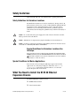
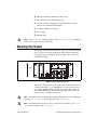
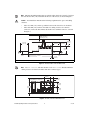
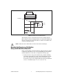
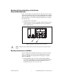
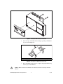
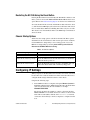
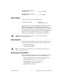
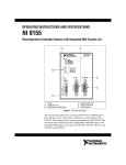
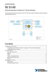
OPERATING INSTRUCTIONS AND SPECIFICATIONS NI 9146 Ethernet Expansion Chassis for C Series Modules 1 NATIONAL INST RUMEN TS NI 9146 POWER STATUS USER FPGA1 4 RESET V C INPUT 9-30 V 15 W MAX 2 3 1 2 LEDs RJ-45 Ethernet Port 10/100 ACT/ LINK 3 4 Power Connector Reset Button Figure 1. NI 9146 Front Panel This document describes how to connect the NI 9146 to a network and how to use the features of the NI 9146. This document also contains specifications for the NI 9146. Safety Guidelines Operate the NI 9146 only as described in these operating instructions. Safety Guidelines for Hazardous Locations The NI 9146 is suitable for use in Class I, Division 2, Groups A, B, C, D, T4 hazardous locations; Class 1, Zone 2, AEx nC IIC T4 and Ex nL IIC T4 hazardous locations; and nonhazardous locations only. Follow these guidelines if you are installing the NI 9146 in a potentially explosive environment. Not following these guidelines may result in serious injury or death. Caution Do not disconnect the power supply wires and connectors from the controller unless power has been switched off. Caution Substitution of components may impair suitability for Class I, Division 2. Caution For Zone 2 applications, install the CompactRIO system in an enclosure rated to at least IP 54 as defined by IEC 60529 and EN 60529. Special Conditions for Hazardous Locations Use in Europe Some chassis have been evaluated as Ex nA nL IIC T4 equipment under DEMKO Certificate No. 07 ATEX 0626664X. Each such chassis is marked II 3G and is suitable for use in Zone 2 hazardous locations, in ambient temperatures of –40 ≤ Ta ≤ 70 °C. Special Conditions for Marine Applications Some chassis are Lloyd’s Register (LR) Type Approved for marine applications. To verify Lloyd’s Register certification, visit ni.com/ certification and search for the LR certificate, or look for the Lloyd’s Register mark on the chassis. What You Need to Install the NI 9146 Ethernet Expansion Chassis ❑ NI 9146 Ethernet expansion chassis ❑ NI-RIO Software DVD ❑ C Series I/O modules NI 9146 Operating Instructions and Specifications 2 ni.com ❑ DIN rail mount kit (for DIN rail mounting only) ❑ Panel mount kit (for panel mounting only) ❑ Two M4 or number 8 flathead screws (for mounting the chassis without one of the listed mounting kits) ❑ A number 2 Phillips screwdriver ❑ Power supply ❑ Ethernet cable Notes Visit ni.com/info and enter the Info Code rdsoftwareversion to determine which software you need to use the NI 9146. Mounting the Chassis You can mount the chassis horizontally on a flat, vertical, metallic surface such as a panel or wall. The maximum allowable ambient temperature for operation in this configuration is 70 °C. Figure 2 shows the chassis mounted horizontally. NATIONAL INST RUMEN TS NI 9146 POWER STATUS USER FPGA1 Up RESET V C INPUT 9-30 V 15 W MAX ACT/ LINK 10/100 Figure 2. NI 9146 Mounted Horizontally You can also mount the chassis on a panel or wall in other orientations, on a non-metallic surface, on a 35 mm DIN rail, on a rack, in an enclosure, or on a desktop. Mounting the chassis in these or other configurations can reduce the maximum allowable ambient temperature and can affect the typical accuracy of modules in the chassis. For information about how different mounting configurations can cause temperature derating, go to ni.com/info and enter the Info Code criomounting. Note Note For information about typical accuracy specifications for modules, go to ni.com/ info and enter the Info Code criotypical. © National Instruments 3 NI 9146 Operating Instructions and Specifications Note Measure the ambient temperature at each side of the chassis, 63.5 mm (2.5 in.) from the side and 25.4 mm (1 in.) forward from the rear of the chassis, as shown in Figure 3. Your installation must meet the following requirements for space and cabling clearance: Caution • Allow 25.4 mm (1 in.) on the top and the bottom of the chassis for air circulation. • Allow 50.8 mm (2 in.) in front of modules for cabling clearance for common connectors, such as the 10-terminal, detachable screw terminal connector, as shown in Figure 3. Cabling Clearance 50.8 mm (2.00 in.) 63.5 mm (2.50 in.) 63.5 mm (2.50 in.) 29.1 mm (1.14 in.) 48.4 mm (1.91 in.) 64.3 mm (2.53 in.) 2 1 25.4 mm (1 in.) 1 1 25.4 mm (1 in.) 178.1 mm (7.01 in.) 4 mm (0.16 in.) Measure ambient temperature here. 2 Chassis Grounding Screw Figure 3. NI 9146, Bottom View with Dimensions Note Go to ni.com/info and enter the Info Code rdcrioconn to find the minimum cabling clearance for C Series modules with other connector types. 47.2 mm (1.86 in.) 30.6 mm (1.2 in.) Cooling Outline 25.4 mm (1 in.) NATIONAL INST RUMEN TS NI 9146 POWER STATUS USER FPGA1 47.0 mm (1.85 in.) 87.3 mm (3.44 in.) RESET 41.1 mm (1.62 in.) V C INPUT 9-30 V 15 W MAX ACT/ LINK 10/100 Cooling Outline 25.4 mm (1 in.) Figure 4. NI 9146, Front View with Dimensions NI 9146 Operating Instructions and Specifications 4 ni.com 2X M4X0.7 29.1 mm (1.15 in.) 44.1 mm (1.54 in.) 44.0 mm (1.73 in.) ] 74.0 mm (2.91 in.) Figure 5. NI 9146, Side View with Dimensions The following sections contain instructions for the mounting methods. Before using any of these mounting methods, record the serial number from the back of the chassis. You will be unable to read the serial number after you have mounted the chassis. Caution Make sure that no I/O modules are in the chassis before mounting it. Mounting the Chassis on a Flat Surface Using the NI 9904 Panel Mount Kit Panel or wall mounting is the best method for applications that are subject to high shock and vibration. You can use the NI 9904 panel mount kit to mount the NI 9146 on a flat surface. Complete the following steps. 1. © National Instruments Fasten the chassis to the panel mount kit using a number 2 Phillips screwdriver and two M4 × 25 screws. National Instruments provides these screws with the panel mount kit. You must use these screws because they are the correct depth and thread for the panel. Tighten the screws to a maximum torque of 1.3 N ⋅ m (11.5 lb ⋅ in.). 5 NI 9146 Operating Instructions and Specifications Figure 6. Installing the Panel Mount Accessory on the NI 9146 215.9 mm (8.5 in.) 29.5 mm (1.16 in.) 9.5 mm (0.38 in.) NATIONAL INST RUMEN TS 235.0 mm (9.25 in.) 27.3 mm (1.08 in.) 7.2 mm (0.29 in.) NI 9146 POWER STATUS USER FPGA1 RESET 31.7 mm (1.25 in.) V C INPUT 9-30 V 15 W MAX ACT/ LINK 63.5 mm (2.50 in.) 88.1 mm (3.47 in.) 10/100 Figure 7. Dimensions of NI 9146 with Panel Mount Accessory Installed 2. Caution Fasten the NI 9904 panel to the wall using the screwdriver and screws that are appropriate for the wall surface. The maximum screw size is M4 or number 8. Make sure that no I/O modules are in the chassis before removing it from the panel. NI 9146 Operating Instructions and Specifications 6 ni.com Mounting the Chassis Directly on a Flat Surface Using the Mounting Holes Panel or wall mounting is the best method for applications that are subject to high shock and vibration. If you do not have the NI 9904 panel mount kit and do not require the portability that the NI 9904 affords, you can mount the chassis directly on a flat surface using the mounting holes. Complete the following steps. 1. Align the chassis on the surface. 2. Fasten the chassis to the surface using M4 or number 8 flathead screws, as shown in Figure 8. National Instruments does not provide these screws with the chassis. NATIONAL INST RUMEN TS NI 9146 POWER STATUS USER FPGA1 RESET V C INPUT 9-30 V 15 W MAX ACT/ LINK 10/100 Figure 8. Mounting the Chassis Directly on a Flat Surface Caution Make sure that no I/O modules are in the chassis before removing it from the surface. Mounting the Chassis on a DIN Rail You can order the NI 9912 DIN rail mount kit if you want to mount the chassis on a DIN rail. You need one clip for mounting the chassis on a standard 35 mm DIN rail. Complete the following steps to mount the chassis on a DIN rail. 1. © National Instruments Fasten the DIN rail clip to the chassis using a number 2 Phillips screwdriver and two M4 × 25 screws. National Instruments provides these screws with the DIN rail mount kit. Tighten the screws to a maximum torque of 1.3 N ⋅ m (11.5 lb ⋅ in.). 7 NI 9146 Operating Instructions and Specifications Figure 9. Installing the DIN Rail Clip on the NI 9146 2. Insert one edge of the DIN rail into the deeper opening of the DIN rail clip, as shown in Figure 10. 1 2 3 1 DIN Rail Clip 2 DIN Rail 3 DIN Rail Spring Figure 10. One Edge of the DIN Rail Inserted in a Clip 3. Caution Press down firmly on the chassis to compress the spring until the clip locks in place on the DIN rail. Make sure that no I/O modules are in the chassis before removing it from the DIN rail. NI 9146 Operating Instructions and Specifications 8 ni.com Mounting the Chassis on a Desktop Using the NI 9901 Desktop Mounting Kit You can use the NI 9901 desktop mounting kit to mount the chassis on a desktop. You must install the adapter bracket using two M3 × 20 screws. The adapter bracket and the screws are included in the kit. Refer to the NI 9901 documentation for information about mounting the chassis on a desktop. Installing C Series I/O Modules in the Chassis Figure 11 shows the mechanical dimensions of C Series I/O modules. 88.1 mm (3.47 in.) 70.7 mm (2.78 in.) 22.9 mm (0.9 in.) Figure 11. C Series I/O Module, Front and Side View with Dimensions Complete the following steps to install a C Series I/O module in the chassis. © National Instruments 1. Make sure that no I/O-side power is connected to the I/O module. If the system is in a nonhazardous location, the chassis power can be on when you install I/O modules. 2. Align the I/O module with an I/O module slot in the chassis as shown in Figure 12. The module slots are labeled 1 to 4, left to right. 9 NI 9146 Operating Instructions and Specifications 1 2 1 Insertion Groove 2 Latch Figure 12. Installing an I/O Module in the Chassis 3. Squeeze the latches and insert the I/O module into the module slot. 4. Press firmly on the connector side of the I/O module until the latches lock the I/O module into place. 5. Repeat these steps to install additional I/O modules. Removing I/O Modules from the Chassis Complete the following steps to remove a C Series I/O module from the chassis. 1. Make sure that no I/O-side power is connected to the I/O module. If the system is in a nonhazardous location, the chassis power can be on when you remove I/O modules. 2. Squeeze the latches on both sides of the module and pull the module out of the chassis. NI 9146 Operating Instructions and Specifications 10 ni.com Connecting the Chassis to Earth Ground You must connect the chassis grounding screw to earth ground. Refer to Figure 3 for the location of the grounding screw. Complete the following steps to connect to earth ground: 1. Attach a ring lug to a 1.6 mm2 (14 AWG) or larger wire. 2. Remove the grounding screw from the grounding terminal on the right side of the chassis. 3. Attach the ring lug to the grounding terminal. 4. Tighten the grounding screw to 0.5 N · m (4.4 lb · in.) of torque. 5. Attach the other end of the wire to earth ground using a method appropriate for the application. If you use shielded cabling to connect to a C Series I/O module with a plastic connector, you must attach the cable shield to the chassis grounding terminal using 1.3 mm2 (16 AWG) or larger wire. Use shorter wire for better EMC performance. Note For more information about earth ground connections, go to ni.com/info and enter the Info Code earthground. Connecting the Chassis to a Network Connect the chassis to an Ethernet network using Ethernet port 1 on the front panel. Use a standard Category 5 (CAT-5) or better shielded, twisted-pair Ethernet cable to connect the chassis to an Ethernet hub or a computer. Caution To prevent data loss and to maintain the integrity of your Ethernet installation, do not use a cable longer than 100 m. The first time you power up the chassis, it attempts to initiate a DHCP network connection. If the chassis is unable to initiate a DHCP connection, it connects to the network with a link-local IP address with the form 169.254.x.x. After powerup, you must install software on the chassis and configure the network settings in Measurement & Automation Explorer (MAX). Installing software may change the network behavior of the chassis. For information about network behavior by installed software version, go to ni.com/info and enter the Info Code ipconfigcrio. Note © National Instruments 11 NI 9146 Operating Instructions and Specifications Wiring Power to the Chassis The NI 9146 requires an external power supply that meets the specifications in the Power Requirements section. The NI 9146 filters and regulates the supplied power and provides power for all of the I/O modules. The NI 9146 has one layer of reverse-voltage protection. Complete the following steps to connect a power supply to the chassis. 1. Ensure that the power supply is turned off. Caution Do not install or remove the power connector from the front panel of the NI 9146 while power is applied. 2. Connect the positive lead of the power supply to the V terminal of the COMBICON power connector shipped with the NI 9146, and tighten the terminal screw. Figure 13 shows the terminal screws, which secure the wires in the screw terminals, and the connector screws, which secure the power connector on the front panel. 2 1 1 Terminal Screws V C 2 2 Connector Screws Figure 13. COMBICON Power Connector 3. Connect the negative lead of the power supply to the C terminal of the power connector and tighten the terminal screw. 4. Install the power connector on the front panel of the NI 9146 and tighten the connector screws. 5. Turn on the power supply. Powering On the NI 9146 When you apply power to the NI 9146, the chassis runs a power-on self test (POST). During the POST, the Power and Status LEDs turn on. The Status LED turns off, indicating that the POST is complete. If the LEDs do not behave in this way when the system powers on, refer to the Understanding LED Indications section. NI 9146 Operating Instructions and Specifications 12 ni.com Restarting the NI 9146 Using the Reset Button Pressing the Reset button restarts the NI 9146. The FPGA continues to run unless you have selected the Autoload VI on device reboot chassis reset option. Refer to the Chassis Startup Options section for more information. To restart the NI 9146 in safe mode, hold the Reset button down for about 5 s, until the Status LED lights yellow, then release the button. The chassis reboots and the Status LED starts blinking three times every few seconds. The chassis is now in Safe Mode. Refer to the MAX help for information about safe mode. Chassis Startup Options Table 1 lists the startup options available for the NI 9146. These options determine how the chassis behaves when it starts up in various conditions. Use the RIO Device Setup utility to select startup options. Access the RIO Device Setup utility by selecting Start»All Programs»National Instruments»NI-RIO»RIO Device Setup. Table 1. NI 9146 Reset Options Startup Option Behavior Do Not Autoload VI Does not load the FPGA bit stream from flash memory. Autoload VI on device powerup Loads the FPGA bit stream from flash memory to the FPGA when the chassis powers on. Autoload VI on device reboot Loads the FPGA bit stream from flash to the FPGA when you reboot the chassis either with or without cycling power. Configuring IP Settings When you power on the NI 9146 for the first time, it boots into safe mode because there is no software installed on it. This section describes how to configure the IP settings and install software on the chassis. Complete the following steps. 1. Launch MAX on the host computer and expand Remote Systems in the MAX configuration tree. MAX lists the NI 9146 as the model name of the chassis followed by the serial number, for example, NI9146-XXXXXXXX. The chassis automatically attempts to connect to the network using DHCP. If DHCP is not available, the chassis connects to the network with a link-local IP address with the form 169.254.x.x. You must connect the chassis directly to the host computer to configure it in this state. © National Instruments 13 NI 9146 Operating Instructions and Specifications 2. Select the chassis under Remote Systems to see the Network Settings tab in the middle pane of MAX. 3. Enter a name for the chassis in the Name field. 4. Select settings for the chassis in the IP Settings section, then click Apply. For information about configuring network settings, refer to the Configuring Network Settings book of the MAX Remote Systems Help. In MAX, click Help»Help Topics»Remote Systems. On the Contents tab, browse to LabVIEW Real-Time Target Configuration»Configuring Network Settings. Note 5. When you click Apply, you are prompted to reboot the chassis for the changes to take effect. Click Yes. You can also reboot the chassis by right-clicking the name under Remote Systems and selecting Reboot. 6. After rebooting, the chassis appears under Remote Systems with the assigned name. Expand the chassis and select Software. 7. Click Add/Remove Software in the toolbar to launch the LabVIEW Real-Time Software Wizard. 8. Install the Recommended Software Set that appears in the LabVIEW Real-Time Software Wizard. For more information about configuring the chassis in MAX, refer to the MAX Help. For information about installing and using LabVIEW FPGA, refer to the LabVIEW FPGA User Manual. Understanding LED Indications POWER STATUS USER FPGA1 Figure 14. NI 9146 LEDs POWER LED The POWER LED is lit while the NI 9146 is powered on. This LED indicates that the power supply connected to the chassis is adequate. NI 9146 Operating Instructions and Specifications 14 ni.com STATUS LED The STATUS LED is off during normal operation. The NI 9146 indicates specific error conditions by flashing the STATUS LED a certain number of times every few seconds, as shown in Table 2. Table 2. Status LED Indications Number of Flashes Every Few Seconds Indication 2 The chassis has detected an error in its software. This usually occurs when an attempt to upgrade the software is interrupted. Reinstall software on the chassis. Refer to the Measurement & Automation Explorer Help for information about installing software on the chassis. 3 The chassis is in safe mode. Refer to the Measurement & Automation Explorer Help for information about safe mode. 4 The software has crashed twice without rebooting or cycling power between crashes. This usually occurs when the chassis runs out of memory. Review your RT VI and check the memory usage. Modify the VI as necessary to solve the memory usage issue. Continuously flashing or solid The chassis has detected an unrecoverable error. Contact National Instruments. USER FPGA1 LED You can use the USER FPGA LED to help debug your application or easily retrieve application status. Use the LabVIEW FPGA Module and NI-RIO software to define the USER FPGA1 LED to meet the needs of your application. Refer to LabVIEW Help for information about programming this LED. Troubleshooting Network Communication If the NI 9146 cannot communicate with the network, you can perform the following troubleshooting steps. © National Instruments 1. Hold the Reset button down for about 5 s, until the Status LED lights yellow, then release the button. The chassis reboots and the Status LED starts blinking three times every few seconds. The chassis is now in Safe Mode. 2. Repeat step 1. The Status LED repeats the same behavior. The chassis is now in Safe Mode with IP Reset. 3. Configure the IP and other network settings in MAX. 4. Press and release the Reset button to reboot the chassis. 15 NI 9146 Operating Instructions and Specifications Where to Go from Here Now that you have set up the NI 9146 and configured it on your network, you can start using it in your applications. The following figure shows the main components of the CompactRIO documentation that you may find helpful as you program and use the NI 9146. ni.com/info rdcriostartup This Document Installation and Specifications Troubleshooting Tips, Tutorials, Examples, and More r Help fo MAX ctRIO a Comp lp» W Heries e LabVIE S C » and NI-RIO ence Refercedures Pro rk Netwo on ati r u g fi Con actRIO Comp Using r Application in You Figure 15. CompactRIO Documentation NI 9146 Operating Instructions and Specifications 16 ni.com Specifications The following specifications are typical for the –40 to 70 °C operating temperature range unless otherwise noted. Network Network interface................................... 10BaseT and 100BaseTX Ethernet Compatibility ......................................... IEEE 802.3 Communication rates ............................. 10 Mbps, 100 Mbps, auto-negotiated Maximum cabling distance .................... 100 m/segment Reconfigurable FPGA FPGA type.............................................. Xilinx Spartan-6 LX 45 Number of flip-flops .............................. 54,576 Number of 6-input LUTs ....................... 27,288 Number of DSP 48s ............................... 58 Available block RAM ............................ 2,088 kbits Number of DMA channels ..................... 5 Power Requirements Caution You must use a UL Listed ITE power supply marked LPS with the NI 9146. Recommended power supply ................. 24 W, 24 VDC Power consumption................................ 15 W maximum Power supply input range....................... 9 to 30 V Note The power consumption specifications in this document are maximum values for a LabVIEW FPGA application compiled at 40 MHz. Your application power requirements may be different. To calculate the power requirements of the NI 9146, add the power consumption/dissipation for the chassis and the I/O modules you are using. Keep in mind that the resulting total power consumption is a maximum value and that the NI 9146 may require less power in your application. For more information about the I/O module power requirements, refer to the module operating instructions. © National Instruments 17 NI 9146 Operating Instructions and Specifications Physical Characteristics If you need to clean the chassis, wipe it with a dry towel. Screw-terminal wiring ............................0.5 to 2.5 mm 2 (24 to 12 AWG) copper conductor wire with 10 mm (0.39 in.) of insulation stripped from the end Torque for screw terminals.....................0.5 to 0.6 N · m (4.4 to 5.3 lb · in.) Weight ....................................................643 g (22.7 oz) Environmental Operating temperature (IEC 60068-2-1, IEC 60068-2-2) ...........–40 to 70 °C To meet this operating temperature range, you must compile your LabVIEW FPGA application at 40 MHz or slower and follow the guidelines in the installation instructions for your system. Note Storage temperature (IEC 60068-2-1, IEC 60068-2-2) ...........–40 to 85 °C Ingress protection ...................................IP 40 Operating humidity (IEC 60068-2-56) ...................................10 to 90% RH, noncondensing Storage humidity (IEC 60068-2-56) ...................................5 to 95% RH, noncondensing Maximum altitude...................................2,000 m Pollution Degree (IEC 60664) ................2 Indoor use only Shock and Vibration To meet these specifications, you must panel mount the chassis and affix ferrules to the ends of the power terminal wires. Operating shock (IEC 60068-2-27) ...................................30 g, 11 ms half sine 50 g, 3 ms half sine, 18 shocks at 6 orientations NI 9146 Operating Instructions and Specifications 18 ni.com Operating vibration, random (IEC 60068-2-64) ................................... 5 grms, 10 to 500 Hz Operating vibration, sinusoidal (IEC 60068-2-6) ..................................... 5 g, 10 to 500 Hz Safety Voltages Connect only voltages that are within these limits. V terminal to C terminal ........................ 30 V max, Measurement Category I Measurement Category I is for measurements performed on circuits not directly connected to the electrical distribution system referred to as MAINS voltage. MAINS is a hazardous live electrical supply system that powers equipment. This category is for measurements of voltages from specially protected secondary circuits. Such voltage measurements include signal levels, special equipment, limited-energy parts of equipment, circuits powered by regulated low-voltage sources, and electronics. Caution Do not connect the system to signals or use for measurements within Measurement Categories II, III, or IV. Safety Standards This product meets the requirements of the following standards of safety for electrical equipment for measurement, control, and laboratory use: • IEC 61010-1, EN 61010-1 • UL 61010-1, CSA 61010-1 Note For UL and other safety certifications, refer to the product label or the Online Product Certification section. Electromagnetic Compatibility This product meets the requirements of the following EMC standards for electrical equipment for measurement, control, and laboratory use: © National Instruments • EN 61326 (IEC 61326): Class A emissions; Industrial immunity • EN 55011 (CISPR 11): Group 1, Class A emissions • AS/NZS CISPR 11: Group 1, Class A emissions • FCC 47 CFR Part 15B: Class A emissions • ICES-001: Class A emissions 19 NI 9146 Operating Instructions and Specifications For the standards applied to assess the EMC of this product, refer to the Online Product Certification section. Note Note For EMC compliance, operate this product according to the documentation. CE Compliance This product meets the essential requirements of applicable European Directives as follows: • 2006/95/EC; Low-Voltage Directive (safety) • 2004/108/EEC; Electromagnetic Compatibility Directive (EMC) Online Product Certification Refer to the Declaration of Conformity (DoC) for this product for additional regulatory compliance information. To obtain product certifications and the DoC for this product, visit ni.com/ certification, search by model number or product line, and click the appropriate link in the Certification column. Environmental Management NI is committed to designing and manufacturing products in an environmentally responsible manner. NI recognizes that eliminating certain hazardous substances from our products is beneficial to the environment and to NI customers. For additional environmental information, refer to the NI and the Environment Web page at ni.com/environment. This page contains the environmental regulations and directives with which NI complies, as well as other environmental information not included in this document. Waste Electrical and Electronic Equipment (WEEE) EU Customers At the end of the product life cycle, all products must be sent to a WEEE recycling center. For more information about WEEE recycling centers, National Instruments WEEE initiatives, and compliance with WEEE Directive 2002/96/EC on Waste and Electronic Equipment, visit ni.com/environment/weee. ⬉ᄤֵᙃѻક∵ᶧࠊㅵ⧚ࡲ⊩ ˄Ё RoHS˅ Ёᅶ᠋ National Instruments ヺড়Ё⬉ᄤֵᙃѻકЁ䰤ࠊՓ⫼ᶤѯ᳝ᆇ⠽䋼ᣛҸ (RoHS)DŽ ݇Ѣ National Instruments Ё RoHS ড়㾘ᗻֵᙃˈ䇋ⱏᔩ ni.com/environment/rohs_chinaDŽ (For information about China RoHS compliance, go to ni.com/environment/rohs_china.) NI 9146 Operating Instructions and Specifications 20 ni.com Hazardous Locations U.S. (UL)................................................ Class I, Division 2, Groups A, B, C, D, T4; Class 1, Zone 2, AEx nC IIC T4 and Ex nC IIC T4 Canada (C-UL)....................................... Class I, Division 2, Groups A, B, C, D, T4; Class 1, Zone 2, Ex nL IIC T4 Europe (DEMKO).................................. Ex nA nL IIC T4 Where to Go for Support The National Instruments Web site is your complete resource for technical support. At ni.com/support you have access to everything from troubleshooting and application development self-help resources to email and phone assistance from NI Application Engineers. A Declaration of Conformity (DoC) is our claim of compliance with the Council of the European Communities using the manufacturer’s declaration of conformity. This system affords the user protection for electromagnetic compatibility (EMC) and product safety. You can obtain the DoC for your product by visiting ni.com/certification. If your product supports calibration, you can obtain the calibration certificate for your product at ni.com/calibration. National Instruments corporate headquarters is located at 11500 North Mopac Expressway, Austin, Texas, 78759-3504. National Instruments also has offices located around the world to help address your support needs. For telephone support in the United States, create your service request at ni.com/support and follow the calling instructions or dial 512 795 8248. For telephone support outside the United States, visit the Worldwide Offices section of ni.com/niglobal to access the branch office Web sites, which provide up-to-date contact information, support phone numbers, email addresses, and current events. © National Instruments 21 NI 9146 Operating Instructions and Specifications LabVIEW, National Instruments, NI, ni.com, the National Instruments corporate logo, and the Eagle logo are trademarks of National Instruments Corporation. Refer to the Trademark Information at ni.com/trademarks for other National Instruments trademarks. Other product and company names mentioned herein are trademarks or trade names of their respective companies. For patents covering National Instruments products/technology, refer to the appropriate location: Help»Patents in your software, the patents.txt file on your media, or the National Instruments Patent Notice at ni.com/patents. You can find information about end-user license agreements (EULAs) and third-party legal notices in the NI-RIO Device Drivers Readme. Refer to the Export Compliance Information at ni.com/legal/export-compliance for the National Instruments global trade compliance policy and how to obtain relevant HTS codes, ECCNs, and other import/export data. © 2012 National Instruments. All rights reserved. 375649A-01 Aug12