1
Operating Instructions <Installation Guide>
Installation Instructions provided
Center Module
Model No.
English
Français
Before attempting to connect or operate this product,
please read these instructions carefully and save this manual for future use.
No model number suffix is shown in this Operating Instructions.
ENGLISH VERSION
Safety precautions
FEDERAL COMMUNICATIONS COMMISSION INTERFERENCE STATEMENT
This equipment has been tested and found to comply with the limits for a Class A digital device, pursuant to part 15 of the
FCC Rules. These limits are designed to provide reasonable protection against harmful interference when the equipment
is operated in a commercial environment. This equipment generates, uses, and can radiate radio frequency energy and, if
not installed and used in accordance with the instruction manual, may cause harmful interference to radio communications.
Operation of this equipment in a residential area is likely to cause harmful interference in which case the user will be required
to correct the interference at his own expense.
Changes or modifications not expressly approved by the party responsible for compliance could void the user’s authority to
operate the equipment.
This transmitter must not be co-located or operated in conjunction with any other antenna or transmitter.
This equipment complies with FCC/IC radiation exposure limits set forth for an uncontrolled environment and meets the FCC
radio frequency (RF) Exposure Guidelines in Supplement C to OET65 and RSS-102 of the IC radio frequency (RF) Exposure
rules. This equipment should be installed and operated keeping the radiator at least 20 cm or more away from person’s body
(excluding extremities: hands, wrists, feet and ankles).
This device complies with Part 15 of FCC Rules and Industry Canada licence-exempt RSS standard(s). Operation is subject
to the following two conditions: (1) this device may not cause interference, and (2) this device must accept any interference,
including interference that may cause undesired operation of this device.
CAUTION
RISK OF ELECTRIC SHOCK
DO NOT OPEN
CAUTION: TO REDUCE THE RISK OF ELECTRIC SHOCK,
DO NOT REMOVE COVER (OR BACK).
NO USER SERVICEABLE PARTS INSIDE.
REFER TO SERVICING TO QUALIFIED SERVICE PERSONNEL.
The lightning flash with arrowhead symbol, within an
equilateral triangle, is intended to alert the user to the
presence of uninsulated “dangerous voltage” within the
product’s enclosure that may be of sufficient magnitude
to constitute a risk of electric shock to persons.
The exclamation point within an equilateral triangle is
intended to alert the user to the presence of important
operating and maintenance (service) instructions in
the literature accompanying the appliance.
WARNING:
p
p
p
p
p
p
p
p
p
p
p
p
p
p
2
This apparatus must be earthed.
Apparatus shall be connected to a main socket outlet with a protective earthing connection.
The mains plug or an appliance coupler shall remain readily operable.
To reduce the risk of fire or electric shock, do not expose this apparatus to rain or moisture.
The apparatus should not be exposed to dripping or splashing and that no objects filled with liquids, such as vases, should
be placed on the apparatus.
All work related to the installation of this product should be made by qualified service personnel or system installers.
To prevent injury, this apparatus must be securely attached to the floor/wall in accordance with the installation instructions.
The connections should comply with local electrical code.
The risk of hearing impairment due to exposure to excessive sound levels may be reduced by listening at lower volumes
and for shorter durations.
Operating near 1.9 GHz electrical appliances may cause interference. Move away from the electrical appliances.
This transmitter must not be co-located or operated in conjunction with any other antenna or transmitter.
MEDICAL:
Consult the manufacturer of any personal medical devices, such as pacemakers, to determine if they are adequately
shielded from external RF (radio frequency) energy. (The unit operates in the frequency range of 1.92 GHz to 1.93 GHz,
and the power output level is 115mW max)
Do not use the unit in health care facilities if any regulations posted in the area instruct you not to do so. Hospitals or health
care facilities may be using equipment that could be sensitive to external RF (radio frequency) energy.
The installation shall be carried out in accordance with all applicable installation rules.
To prevent fire or electric shock hazard, do not expose this apparatus to rain or moisture.
Safety precautions
For U.S.A.
The model number and serial number of this product may
be found on the surface of the unit.
You should note the model number and serial number of
this unit in the space provided and retain this book as a
permanent record of your purchase to aid identification in
the event of theft.
Model No.
Serial No.
For U.S.A.
CAUTION:
The FCC ID number for this radio equipment is listed
below.
FCC ID: ACJ9TAWX-CC411
FCC ID: ACJ9TAWX-CC412
CAUTION:
p Danger of explosion if battery is incorrectly replaced.
Replace only with the same or equivalent type.
p These servicing instructions are for use by qualified
service personnel only. To reduce the risk of electric
shock do not perform any servicing other than that
contained in the operating instructions unless you are
qualified to do so.
p Any changes or modifications not expressly approved
by the party responsible for compliance could void the
user’s authority to operate the equipment.
p Shielded (STP) LAN cables must be used with this unit
to ensure compliance with EMC standards.
For Canada
ICES-003
CAN ICES-3(A)/NMB-3(A)
English
For Canada
For U.S.A.
This product contains a CR Coin Cell Lithium Battery
which contains Perchlorate Material – special handling
may apply. See
www.dtsc.ca/gov/hazardouswaste/perchlorate/
A lithium-ion battery that is recyclable
powers the product you have purchased.
Please call 1-800-8-BATTERY for information
on how to recycle this battery.
RSS-Gen
p Under Industry Canada regulations, this radio
transmitter may only operate using an antenna of a
type and maximum (or lesser) gain approved for the
transmitter by Industry Canada. To reduce potential
radio interference to other users, the antenna type
and its gain should be so chosen that the equivalent
isotropically radiated power (e.i.r.p.) is not more than
that necessary for successful communication.
IMPORTANT SAFETY INSTRUCTIONS
1) Read these instructions.
2) Keep these instructions.
3) Heed all warnings.
4) Follow all instructions.
5) Do not use this apparatus near water.
6) Clean only with dry cloth.
7) Do not install near any heat sources such as radiators, heat registers, stoves, or other apparatus (including amplifiers) that
produce heat.
8) Do not defeat the safety purpose of the polarized or grounding-type plug. A polarized plug has two blades with one wider than
the other. A grounding type plug has two blades and a third grounding prong. The wide blade or the third prong are provided
for your safety. If the provided plug does not fit into your outlet, consult an electrician for replacement of the obsolete outlet.
9) Protect the power cord from being walked on or pinched particularly at plugs, convenience receptacles, and the point
where they exit from the apparatus.
10) Only use attachments/accessories specified by the manufacturer.
11) Use only with the cart, stand, tripod, bracket, or table specified by the manufacturer, or sold with the apparatus. When a cart
is used, use caution when moving the cart/apparatus combination to avoid injury from tip-over.
12) Unplug this apparatus during lightning storms or when unused for long periods of time.
13) Refer all servicing to qualified service personnel. Servicing is required when the apparatus has been damaged in any
way, such as power-supply cord or plug is damaged, liquid has been spilled or objects have fallen into the apparatus, the
apparatus has been exposed to rain or moisture, does not operate normally, or has been dropped.
3
Contents
Safety precautions ........................................................... 2
Screen operations .......................................................... 29
Before use ......................................................................... 5
Basic screen operations ............................................... 29
Preface ........................................................................... 5
Entering the settings .................................................... 29
Features ......................................................................... 5
Inputting characters ..................................................... 30
System diagram ............................................................. 5
Inputting the date and time .......................................... 30
Operation ....................................................................... 6
Adjusting the volume level ............................................ 30
Concerning the Operating Instructions .......................... 7
Operating procedures .................................................... 31
Standard accessories .................................................... 7
Basic operations .......................................................... 31
Trademarks and registered trademarks ......................... 7
ID Registration ............................................................. 31
Abbreviations ................................................................. 8
Convenient Functions (Other Functions) ..................... 33
Limitation of liability ........................................................ 8
Troubleshooting .............................................................. 36
Disclaimer of warranty .................................................... 8
Network security ............................................................ 8
Precautions ....................................................................... 9
Operating precautions .................................................... 9
Installation precautions ................................................ 10
Major operating controls and their functions .............. 11
Front panel ................................................................... 11
Terminal block .............................................................. 12
Side panel .................................................................... 13
Screen .......................................................................... 14
Description of screens ................................................... 15
Basic screen ................................................................ 15
Setting Information screen ........................................... 16
Password input screen ................................................. 18
Camera monitoring screen ........................................... 18
Quick Operation screen ............................................... 19
Related devices .............................................................. 20
Installation procedures .................................................. 21
Deciding on where to install the Center Module .......... 21
Installation .................................................................... 21
Connections .................................................................... 24
Opening the connector cover ....................................... 24
Securing the power cord .............................................. 24
Wiring the Euroblock connector ................................... 25
Attaching the connector cover ...................................... 27
Examples of connections ............................................. 28
4
Specifications ................................................................. 37
Licenses .......................................................................... 39
Before use
wPreface
The WX-CC411 and WX-CC412 are Center Modules for the wireless intercom systems that are used in drive-thru outlets.
wFeatures
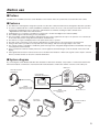
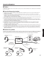
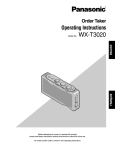
wSystem diagram
By connecting the Center Module and All-In-One Headsets or Belt Packs wirelessly, it is possible to communicate between the
All-In-One Headsets or Belt Packs or between the All-In-One Headsets or Belt Packs and the customers at the order post.
Order post
All-In-One Headset
WX-CH450
Center Module
WX-CC411/WX-CC412
Microphone
Speaker
PAGE
(Communications with
other store personnel)
Belt Pack
WX-CT420
TALK
(Communications with
customers)
Belt Pack
WX-CT420
Vehicle detector
All-In-One Headset
WX-CH450
5
English
p The WX-CC411 is designed for single lane operation of drive-thru outlets; the WX-CC412 is designed for dual lane operation.
p A system compliant with the 1.9 GHz band DECT* standard is used so the voices of the store personnel and customers are
heard clearly and distinctly even in open areas, and interference is minimal, resulting in stable communication.
* Digital Enhanced Cordless Telecommunications
p A high degree of vocal clarity is ensured by a powerful echo canceller and digital noise reduction (DNR).
p The cabinet supports wall-mounting for easy installation.
p The total number of All-in-One Headsets and Belt Packs that can be registered is 32. Up to four operators can communicate
at the same time per lane using All-in-One Headsets and Belt Packs.
p This unit has a 7-Type LCD display with a touch panel, and is easy to operate.
p This unit can be connected to an IP network using Ethernet to enable remote control operations to be performed.
p Using an SD card, it is possible to back up and restore the settings, and save messages unique to the outlet.
p The system contains a scheduler to enable the greeter message to be changed at designated times and reminder messages
to be played back automatically.
p Up to four Network Cameras made by Panasonic can be registered, and their images can be monitored on this unit’s LCD
display.
p Alert signals that have been received can be sent to the All-In-One Headsets or Belt Packs, signals can be output to external
devices, and alert emails can be sent to external destinations.
Before use
wOperation
This system supports the following operations that are suited to drive-thru customers.
Single lane
Operations in an environment in which only one order post is installed are referred to as “single lane” operations.
These lane operations are supported by the WX-CC411.
Hello
ORDER POST
DRIVE-THRU LANE
WINDOW
Dual lane
Operations in an environment in which the order posts are installed in parallel are referred to as “dual lane” operations.
With dual lane operations, the vehicle detectors for lane A and lane B operate independently of each other, and when each of
these vehicle detectors is set to ON, the greeter message for the lane concerned is played back.
These lane operations are supported by the WX-CC412.
Hello
LANE B
ORDER POST
Hello
LANE A
ORDER POST
WINDOW
LANE B
6
DRIVE-THRU LANE
WINDOW
LANE A
Tandem lane
Operations in an environment in which the order posts are installed in series are referred to as “tandem lane” operations. When
the vehicle detector for lane A is OFF and the vehicle detector for lane B is set to ON, a tandem lane message urging the
customer to move to lane A is played back.
These lane operations are supported by the WX-CC412.
Pull forward
LANE A
ORDER POST
LANE B
ORDER POST
WINDOW
LANE B
English
DRIVE-THRU LANE
WINDOW
LANE A
wConcerning the Operating Instructions
The Operating Instructions consist of the Operating Instructions <Installation Guide>, Operating Instructions <Setup
Instructions> (PDF file) and Operating Instructions <Browser Guide> (PDF file).
p Operating Instructions <Installation Guide> (this manual):
These instructions describe how to connect the Center Module with the required devices, how to install them and how to
perform settings (excerpted).
p Operating Instructions <Setup Instructions> (PDF file):
These instructions describe the settings that must be performed before this unit can be used.
p Operating Instructions <Browser Guide> (PDF file):
These instructions explain access from the browser.
To read PDF files, you will need Adobe® Reader® which is available from Adobe Systems. When Adobe® Reader® is not installed
on the PC, download the latest Adobe® Reader® from the Adobe web site and install it.
Important
p Download the “Operating Instructions <Setup Instructions/Browser Guide>” from the home page given below.
http://www.panasonic.com/business/POS-drive-through/manuals.asp
wStandard accessories
Power cord ..................................................................... 1 pc.
Clamp (for securing the power cord to the wall) ............ 1 pc.
Wall mounting bracket ................................................... 1 pc.
Operating Instructions (this manual) .............................. 1 pc.
Power cord clamp .......................................................... 1 pc.
wTrademarks and registered trademarks
p Adobe, Acrobat Reader, and Adobe Reader are either registered trademarks or trademarks of Adobe Systems Incorporated
in the United States and/or other countries.
p SD, SDHC Logo is a trademark of SD-3C, LLC.
p Other names of companies and products contained in these operating instructions may be trademarks or registered
trademarks of their respective owners.
7
Before use
wAbbreviations
The following abbreviations are used in this document.
SDHC and SD memory cards are referred to as “SD cards”.
wLimitation of liability
THIS PUBLICATION IS PROVIDED “AS IS” WITHOUT WARRANTY OF ANY KIND, EITHER EXPRESS OR IMPLIED,
INCLUDING BUT NOT LIMITED TO, THE IMPLIED WARRANTIES OF MERCHANTABILITY, FITNESS FOR ANY PARTICULAR
PURPOSE, OR NON-INFRINGEMENT OF THE THIRD PARTY’S RIGHT.
wDisclaimer of warranty
IN NO EVENT SHALL Panasonic Corporation BE LIABLE TO ANY PARTY OR ANY PERSON, EXCEPT FOR REPLACEMENT
OR REASONABLE MAINTENANCE OF THE PRODUCT, FOR THE CASES, INCLUDING BUT NOT LIMITED TO BELOW:
(1) ANY DAMAGE AND LOSS, INCLUDING WITHOUT LIMITATION, DIRECT OR INDIRECT, SPECIAL, CONSEQUENTIAL OR
EXEMPLARY, ARISING OUT OF OR RELATING TO THE PRODUCT;
(2) PERSONAL INJURY OR ANY DAMAGE CAUSED BY INAPPROPRIATE USE OR NEGLIGENT OPERATION OF THE
USER;
(3) UNAUTHORIZED DISASSEMBLE, REPAIR OR MODIFICATION OF THE PRODUCT BY THE USER;
(4) ANY PROBLEM CAUSING FAILED SIGNAL TRANSMISSION RESULTING IN CONSEQUENTIAL INCONVENIENCE,
LOSS OR DAMAGE, ARISING OUT OF CAUSES SUCH AS SYSTEM MALFUNCTION, FAULT, SET UP OR
INSTALLATION.
(5) ANY PROBLEM, CONSEQUENTIAL INCONVENIENCE, OR LOSS OR DAMAGE, ARISING OUT OF THE SYSTEM
COMBINED BY THE DEVICES OF THIRD PARTY.
(6) PERSONAL INJURY, ANY LOSS OR DAMAGE, ARISING OUT OF THE DROP CAUSED BY THE INCOMPLETE
INSTALLATION.
(7) ANY CLAIM OR ACTION FOR DAMAGES, BROUGHT BY ANY PERSON OR ORGANIZATION BEING PHOTOGENIC
SUBJECT, DUE TO VIOLATION OF PRIVACY WITH THE RESULT OF THAT SURVEILLANCE-CAMERA’S PICTURE,
INCLUDING SAVED DATA, FOR SOME REASON, BECOMES PUBLIC OR IS USED FOR ANY PURPOSE.
(8) LOSS OF REGISTERED DATA CAUSED BY ANY FAILURE.
wNetwork security
As you will use this product connected to a network, your attention is called to the following security risks.
(1) Leakage or theft of information through this product
(2) Use of this product for illegal operations by persons with malicious intent
(3) Interference with or stoppage of this product by persons with malicious intent
It is your responsibility to take precautions such as those described below to protect yourself against the
above network security risks.
p Use this product in a secured network not connected to the Internet.
p If this product is connected to a network that includes PCs, make sure that the system is not infected by computer viruses or
other malicious entities (using a regularly updated anti-virus program, anti-spyware program, etc.).
p Protect your network against unauthorized access by restricting users to those who log in with an authorized user name and
password.
p After this unit has been accessed by the administrator, all the web browsers must be closed without fail.
p The administrator’s password must be changed at regular intervals.
p Apply measures such as user authentication for the servers and the connected devices to protect your network against
leakage or theft of information, including image data, authentication information (user names and passwords), alarm mail
information, FTP server information, etc.
8
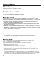
Precautions
wOperating precautions
Touch panel
p Perform touch panel operations using only one finger. If
two or more fingers come into contact with the panel at
the same time, the touch panel may not operate properly.
p Do not use a ballpoint pen or other hard-tipped or sharp
object, including fingernails, to perform touch panel
operations.
p Do not press on the LCD display with too much force.
p Do not use any of the LCD protective films available on
the market. (The touch panel may not operate properly.)
p The inside of the LCD display may become cloudy or
condensation (droplets of water) may form and the
display may not operate properly when the temperature
changes suddenly, such as immediately after airconditioning or heating has been turned on. If this
occurs, leave this unit for about one to two hours before
attempting to use it again.
To cut the power supply
This product has no power switch. To cut the power supply,
unplug the power plug of the product from the AC outlet. If
it is hard to unplug the power cord due to the installation
conditions, connect the power cord of the product to the AC
outlet via the circuit breaker of a distribution board or to the
AC inlet socket of a power supply control unit.
Built-in backup battery
Do not expose the built-in backup battery to excessive heat,
such as direct sunlight or fire.
Camera image update speed
The image update speed may be slower, depending on
the network environment used, the number and setting of
cameras, the subjects, and number of accesses.
9
English
p This unit is for indoor use only.
It cannot be used outdoors.
Avoid installation in a location where the unit will be
exposed to direct sunlight for extended periods or near a
cooling or heating appliance.
Otherwise, deformation, discoloration, malfunctioning
and/or problems in operation may result. Operate the unit
where it will not be splashed or sprayed by water.
p Handle the unit carefully. This product uses parts that
may be damaged by improper handling or storage.
p Do not use this unit in an atmosphere where there are
flammable gases. Otherwise, an explosion may occur,
resulting in injuries.
p Do not install this unit in a location that is susceptible
to salt damage or where corrosive gases are given off.
Otherwise, the mounting parts will deteriorate, and this
unit may fall, resulting in injury or accidents.
p Tighten the screws and bolts using the designated
torque. Otherwise, this unit may fall, resulting in injury or
accidents.
p Install this unit on a surface that can bear its weight.
Otherwise, this unit may fall or topple over, resulting in
injury or accidents. Installation work should be started
only after sufficient reinforcement is completed.
p Insert the AC plug completely. If the plug is not inserted
completely, fire due to overheating or electric shock may
result. Do not use a damaged plug or loose AC outlet.
p Do not pull or insert the AC plug if your hands are wet.
Electric shock may result.
p Do not place containers with water or other liquids on top
of or around the device. If water or other liquids get inside
this unit, a fire or electric shock may result. Immediately
disconnect the power plug, and contact the store where
you purchased this unit.
p Do not insert foreign objects. If water or metal objects
get inside this unit, a fire or electric shock may result.
Immediately disconnect the power plug, and contact the
store where you purchased this unit.
p Do not disassemble this product. Otherwise, it may cause
fire or electric shock.
p Do not do anything that may damage the AC cord or
the AC plug. Do not damage or modify the cord, place
it near hot tools, bend, twist, or pull it forcefully, place
heavy objects on it, or bundle it tightly. Continuing to use
a damaged cord may result in fire, short circuit, or electric
shock. If the cord or plug needs to be repaired, consult
the store where you purchased this unit.
p Do not attempt to install this unit or proceed with any
connections during a thunderstorm. Otherwise, it may
cause fire or electric shock.
p Stop operation immediately if the unit emits smoke,
excessive heat or abnormal smell. These conditions can
cause fire or electric shock. Immediately disconnect the
power plug, and contact the store where you purchased
this unit.
p Do not use this equipment close to an automatic control
equipment like an automatic door fire alarm and so on.
Radio waves from this equipment may cause the trouble
by a malfunction for automatic equipment.
p Do not put this product close to a medical equipment.
(Do not bring this product into operating room, intensive
care units (ICU) and coronary care units (CCU).) Radio
waves from this equipment may cause the trouble by a
malfunction for medical equipment.
p Ask the store where you purchased this unit to do the
installation work. Expertise and experience are required
to install this unit. Otherwise, injuries or damage to this
unit may result. Be sure to ask the store where you
purchased this unit to perform this work.
p Do not put this product on a place with moisture or dirt.
There is the risk of injury.
Precautions
SDHC/SD cards
p Before using an unformatted SDHC or SD card, format it
first using the Center Module. When a card is formatted,
whatever has been recorded on it will be erased. If an
unformatted SDHC or SD card or an SDHC or SD card
formatted on a unit other than the Center Module is
used, it may not work properly or its performance may be
compromised.
p When some SDHC or SD cards are used in this unit,
they may not work properly or their performance may be
compromised. Use of the recommended SDHC and SD
cards is recommended.
Recommended SDHC and SD cards
Manufactured by Panasonic Corporation (sold separately)
SDHC cards: 4 GB, 8 GB, 16 GB, 32 GB
SD cards: 2 GB
(Excluding miniSD cards and microSD cards)
p In many cases when SD cards are formatted or their data
is erased or deleted using the functions of the Center
Module or a personal computer, the data on the cards
may not be erased completely. Before handling a card
over to another party, it is recommended that you use
a commercially available PC software application for
erasing data to erase the data on the card completely.
p When SD cards are to be disposed of, either break them
physically or erase the data on them completely, separate
them in the garbage and dispose of them following the
regulations that are enforced in the locality concerned.
Cleaning the touch panel
p It is recommended that the touch panel be cleaned at
regular intervals.
p If there is any noticeable dirt, dust, oil, grease, etc. on the
touch panel, clean it immediately.
p Wipe off the dirt or dust gently using a soft dry cloth.
p You may damage the LCD display if you wipe or press the
touch panel too forcefully or subject the display to impact
or heavy loads.
p Do not use liquid or spray cleaners. The touch panel
functions may be impaired as a result.
p Do not allow products made of rubber or PVC to remain
in contact with the touch panel for prolonged periods of
time. Doing so may cause discoloration or deterioration.
p Do not use benzene, paint thinners, adhesives, alkali- or
alcohol-based cleaning agents, glass cleaners, waxes,
abrasive cleansers, powdered cleaners, insecticides, etc.
Doing so may cause colors and texture to be degraded.
(When using a chemical cloth for cleaning, read the
caution provided with the chemical cloth product.)
10
wInstallation precautions
WARNING: In order to safeguard against injury, this
device must be mounted on a wall, following the steps in
the Operating Instructions.
Panasonic assumes no responsibility for injuries or
property damage resulting from failures arising out of
improper installation or operation inconsistent with this
documentation.
Avoid installing in the following locations.
p Locations exposed to direct sunlight
p Locations subject to having strong vibration or impact
p Locations which are not level
p Locations under the air conditioner
p Locations near the fryer
p Locations near the grill
p Locations where a chemical agent is used such as a
swimming pool
p Locations near magnetic field sources such as a
television or speakers
p Locations where condensation forms easily, where
temperature changes greatly, humid places
p Locations subject to dust
p Locations subject to water splash or spray
p Locations where radiation or x-ray emissions are produced
The accessory power cord is to be used only with this unit.
Do not use it for any other devices. Similarly, do not use the
power cords of other devices with this unit.
Grounding
Confirm that the wire is connected from the SIGNAL GND
terminal to earth ground. A grounding connection must be
made before connecting the power plug or this product to
the main power supply. When disconnecting the grounding
wire, make sure that the power plug of this product is
disconnected from the main power supply.
Power supply used
The supply voltage of this unit is AC 100 V to 120 V
(50 Hz/60 Hz). Connect this unit to a power supply with a
sufficiently high capacity.
To cut the power supply
This product has no power switch. To cut the power supply,
unplug the power plug of the product from the AC outlet. If
it is hard to unplug the power cord due to the installation
conditions, connect the power cord of the product to the AC
outlet via the circuit breaker of a distribution board or to the
AC inlet socket of a power supply control unit.
Be sure to connect the power cord via any of the following
breaking devices:
p Connect the power cord via a power supply control unit.
p Install the product near a power outlet, and connect the
power cord via the power plug.
p Connect the power cord to the breaker with contact gap
of 3.0 mm or more of a distribution board. The breaker
shall be able to shut down all the poles of the main power
supply except the ground protective conductor.
Setting the time
Before operating this unit, you must set the time. For how
to set the time, refer to the Operating Instructions <Setup
Instructions>.
Major operating controls and their functions
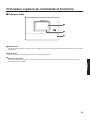
wFront panel
English
LCD display
This is a 7-Type color LCD display. It indicates this unit’s operational status and details of its operations and settings.
Touch panel
This is a 7.8-Type touch panel. It is used to operate this unit.
Terminal cover
This is where the “Euroblock” (a European-style terminal block) for the audio input/output signals and control input/output
signals is housed.
11
Major operating controls and their functions
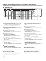
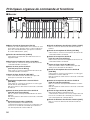
wTerminal block
ロモワユチモ
ロモワユチャ
ヤワヵ ヤヰヮ ヤワヵ ヤヰヮ ヤワヵ ヤワヵ ヤヰヮ ヤワヵ ヵㄙュ ヴヨ ンㄙュ
ヒ
ビ ⿂
⿃
ュユヷリヤユ
モロユンヵ
ヷリュユヰチヰヶヵ
ンヴノビピビヤ
ヒパャモヴユノヵ
ヒパパャモヴユノヵヹ
ヤヰヮ ヤワヵ
⿀
Power input terminal [AC IN]
Connect the accessory power cord to this terminal. After
connecting it, secure the cord using the power cord
clamp. (Refer to p.24 “Securing the power cord”.)
Lane A vehicle detector input [VDET]
This is connected to the vehicle detector installed in
lane A.
Lane B mic input [OUT MIC]
Confirmation window [CHECK]
This window is used for confirmation purposes when this
unit is installed.
Lane A mic input [OUT MIC]
This is connected to the microphone for the order post
installed in lane A.
Lane A speaker output
[OUT SP (8 ȍ) Class2 Wiring]
This is connected to the speaker for the order post
installed in lane A.
This is connected to the microphone for the order post
installed in lane B.
Lane B speaker output
[OUT SP (8 ȍ) Class2 Wiring]
This is connected to the speaker for the order post
installed in lane B.
Lane B line output [LINE OUT]
The same communication that is output from OUT SP of
lane B is output.
Lane B kitchen mic input [AUX MIC]
Lane A line output [LINE OUT]
The same communication that is output from OUT SP of
lane A is output.
This is connected to the gooseneck microphone installed
in the lane B kitchen.
It is used to speak with the customer who has arrived at
the order post for lane B.
Lane A kitchen mic input [AUX MIC]
This is connected to the gooseneck microphone installed
in the lane A kitchen.
It is used to speak with the customer who has arrived at
the order post for lane A.
Lane A kitchen speaker output
[AUX SP (8 ȍ) Class2 Wiring]
This is connected to the speaker installed in the lane A
kitchen.
It is used to speak with the customer who has arrived at
the order post for lane A.
Lane A line input [LINE IN]
External communications can be broadcast
simultaneously to all the All-In-One Headsets or Belt
Packs and to the lane A kitchen speaker.
12
Lane B kitchen speaker output
[AUX SP (8 ȍ) Class2 Wiring]
This is connected to the speaker installed in the lane B
kitchen.
It is used to speak with the customer who has arrived at
the order post for lane B.
Lane B line input [LINE IN]
External communications can be broadcast
simultaneously to all the All-In-One Headsets or Belt
Packs and to the lane B kitchen speaker.
Lane B vehicle detector input [VDET]
This is connected to the vehicle detector installed in
lane B.
External control output [DEVICE]
This external control output is used for alerts.
Using this unit’s settings, this connector is controlled in
response to the reception of alert signals from the All-InOne Headsets or Belt Packs and to the signals from the
alert input.
Alert input [ALERT]
This external input connector is used for alerts. It is
connected to a sensor or other external device.
Serial port [RS-232C]
This port is for controlling the system from a personal
computer.
For details, contact the store where you purchased this
unit.
Video output [VIDEO OUT]
English
This NTSC type of composite connector is for outputting
camera images.
For details, contact the store where you purchased this
unit.
Network port [10BASE-T/100BASE-TX]
This is connected to a 10BASE-T or 100BASE-TX
network, and it connects the Network Camera with the
Center Module.
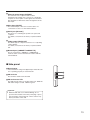
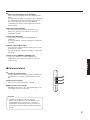
wSide panel
Reset button
Press this button using a fine-tipped object when this unit
is not operating properly to restart this unit.
SD card slot
This is where an SD card is inserted.
SD card access LED
This indicates the status of the SD card access. While the
SD card is being accessed, it blinks in green.
Important
p While the SD card access LED is blinking, do not
eject the SD card, disconnect the power plug or press
the reset button. Performing any of these actions may
destroy the data on the card.
13
Major operating controls and their functions
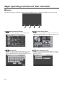
wScreen
The following four buttons, which are separate from the LCD display buttons, are permanently displayed on the touch panel.
!
!
"
Setting Information button
#
#
This button is used to display the settings and statuses.
(Refer to p.16 “Setting Information screen”.)
"
Setting button
This button is used to display the password input screen.
After the password has been confirmed, the setting list
screen is displayed. (Refer to p.18 “Password input screen”.)
14
$
Camera display button
This button is used to display the images of the Panasonic
Network Cameras that have been registered. (Refer to p.18
“Camera monitoring screen”.)
$
Quick Operation button
This button is used to display the Quick Operation screen
that is used with drive-thru operations. (Refer to p.19 “Quick
Operation screen”.)
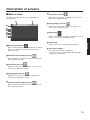
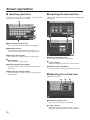
Description of screens
Talk display (lane B)
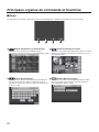
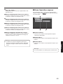
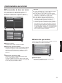
wBasic screen
The basic screen that appears on the LCD display is
described below.
While the store personnel are talking to the customer in
lane B, this is displayed in green.
Paging display (lane B)
While the store personnel at lane B are talking to one
another, this is displayed in green.
REC button
When a communication is being recorded after a security
alert has occurred, this is displayed in red.
Security Alert display
When an alert signal has been received from an external
device or an All-In-One Headset or Belt Pack, this is
displayed in red.
English
Title display
The title of the screen currently displayed appears.
Date & time display
The current date and time are displayed.
“ ” appears in front of the time display during daylight
*
savings time (summer time).
Vehicle detection display (lane A)
When a vehicle has arrived at the order post for lane A,
this is displayed in orange.
Talk display (lane A)
While the store personnel are talking to the customer in
lane A, this is displayed in orange.
Paging display (lane A)
While the store personnel at lane A are talking to one
another, this is displayed in orange.
Vehicle detection display (lane B)
When a vehicle has arrived at the order post for lane B,
this is displayed in green.
15
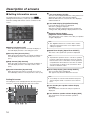
Description of screens
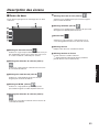
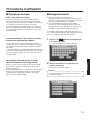
wSetting Information screen
The Setting Information screen appears when
(Setting Information button) on the touch panel is touched.
This unit’s settings and statuses can be confirmed on this
screen.
Lane name display [A] ([B])
The lane name is displayed. The lane setting statuses are
displayed to the right of the lane name display.
When the WX-CC412 is used, lane B is also displayed
underneath lane A.
Lane mode display [Single/Dual/Tandem]
Lane mode that has been set is displayed.
WX-CC411: [Single] is displayed.
WX-CC412: [Dual] is displayed when the tandem lane
setting is OFF, and [Tandem] is displayed when it is ON.
Nighttime Volume display
[Nighttime Volume ON/OFF/AUTO]
The setting status of the volume of the order post speaker
at night is displayed.
Note
p The “Nighttime Volume” is a function that is used to
adjust the volume level of the voice output from the
order post speaker.
Setting Info [Setting Info]
When the Setting Info button is touched, the display on
the LCD display switches to the setting list screen.
Speed Team display [Speed Team ON/OFF]
The status of the speed team operation is displayed.
Security Alert [Security Alert]
When the Security Alert button is touched, the display on
the LCD display switches to the Security Alert screen.
(P.17)
Help Contact [Help Contact]
When the Help Contact button is touched, the display on
the LCD display switches to the Help Contact screen.
(P.18)
System Information [System Info]
Note
p “Speed Team operation” refers to a mode of operation
in which, at busy times when there are more vehicles
than the lanes can accommodate, normal operation is
suspended, the vehicle detectors are shut off, and the
store personnel go directly to the customers in their
vehicles to take their orders.
Cross Beep display [Cross Beep ON/OFF]
When the System Info button is touched, the screen on
the LCD display switches to the System Info screen. (P.18)
The Cross Beep status is displayed.
This appears only when the WX-CC412 is used.
Note
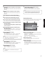
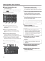
Setting list screen
The setting list screen is displayed when the unit’s power is
turned on or when the [Setting Info] button is touched.
Lane A order post speaker volume display
[Outside]
p “Cross Beep” is a function that sends the beep tone
announcing the arrival of customers across the two
lanes.
The volume level of the lane A order post speaker is
displayed.
Lane A kitchen speaker volume display [AUX]
The volume level of the lane A kitchen speaker is
displayed.
16
Lane A order post microphone volume display
[Outside]
The volume level of the lane A order post microphone is
displayed.
Lane A V/Det Override ON/OFF display
[V/Det Override ON/OFF]
The status of the lane A V/Det Override is displayed.
Note
Lane A kitchen microphone volume display
[AUX]
The volume level of the lane A kitchen microphone is
displayed.
p “V/Det Override” is a function that sets the vehicle
detectors virtually to ON and keeps both the order
post microphone and speaker in the ON setting.
Lane A beep tone volume display [Beep]
The volume level of the lane A beep tone is displayed.
Lane A line input volume display [Line In]
The volume level of the lane A line input is displayed.
Lane A line output volume display [Line Out]
The volume level of the lane A line output is displayed.
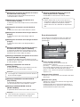
Security Alert screen
The Security Alert screen appears when the [Security Alert]
button on the Setting Information screen is touched.
English
Lane A order post microphone ON/OFF display
[Out Mic ON/OFF]
The setting that determines whether to output the voice
of the lane A order post microphone to the lane A kitchen
speaker is displayed.
Lane A kitchen microphone ON/OFF display
[AUX Mic ON/OFF]
The setting that determines whether to output the voice
of the lane A kitchen microphone to the lane A kitchen
speaker is displayed.
Lane A talk ON/OFF display
[TALK ON/OFF]
The setting that determines whether to output the talk
voice to the lane A kitchen speaker is displayed.
Note
p “Talk” refers to communications between the
customers and store personnel.
Cause and Initiation time
The cause of a security alert that has occurred and the
initiation time are displayed.
[F Button]
: Sent from the store personnel who have
All-In-One Headsets or Belt Packs.
[Alert 1 to 4] : Sent from alert input 1 to 4.
Clear button [Clear]
This is touched to forcibly clear the Security Alert.
Stop button [Stop]
Lane A beep tone ON/OFF display
[Beep ON/OFF]
The setting that determines whether to output the beep
tone to the lane A kitchen speaker is displayed.
This is touched when the Alert Message for the Security
Alert is to be stopped.
This appears when “Alert message playback” has been
set for operations to be performed when a Security Alert
has occurred.
Lane A paging ON/OFF display
[PAGE ON/OFF]
The lane A paging setting is displayed.
Note
p “Paging” refers to communications among store
personnel.
17
Description of screens
Help Contact screen
wPassword input screen
The Help Contact screen appears when the [Help Contact]
button on the LCD display is touched.
The password must be input for verification before operation
moves to the setting screen.
The password input screen appears when
(setting
button) on the touch panel is touched. For details on how to
input the characters, refer to p.30 “Inputting characters”.
The emergency help contact is displayed on this screen. It
can be set on the setting screen. If an email has been set
using the browser ahead of time, an email can be sent from
this screen.
Default password: 12345
Note
p It is not possible to display the email send result even
when, for instance, an email failed to be sent because
the server was down or the wrong email was set.
When installing this unit, check that emails can be
correctly sent ahead of time.
Important
p Change the password at regular intervals for security
purposes.
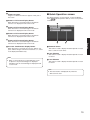
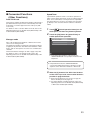
wCamera monitoring screen
System Info screen
The System Info screen appears when the [System Info]
button on the LCD display is touched.
The camera monitoring screen appears on the LCD display
when
(camera display button) on the touch panel is
touched.
Network statuses are shown on this screen.
Camera 1 screen
Images from Network Camera 1 appear on this part of
the screen.
Camera 2 screen
Images from Network Camera 2 appear on this part of
the screen.
Camera 3 screen
Images from Network Camera 3 appear on this part of
the screen.
18
Camera 4 screen
Images from Network Camera 4 appear on this part of
the screen.
Camera 1 full-screen display button
wQuick Operation screen
The Quick Operation screen appears on the LCD display
when
(Quick Operation button) on the touch panel is
touched.
When this button is touched, images from Network
Camera 1 are displayed in full-screen mode.
Camera 2 full-screen display button
When this button is touched, images from Network
Camera 2 are displayed in full-screen mode.
Camera 3 full-screen display button
When this button is touched, images from Network
Camera 3 are displayed in full-screen mode.
Camera 4 full-screen display button
4-screen simultaneous display button
When this button is touched, the screen is split into four
parts, and the images from Network Cameras 1, 2, 3 and
4 are displayed simultaneously.
Common button
This button is used to display the Quick Operation screen
that is common to both lanes.
Lane A button
This button is used to display the Quick Operation screen
for lane A.
Note
p When a camera image is touched while the screen
is split into four parts and images are displayed
simultaneously, the touched image is displayed in fullscreen mode.
Lane B button
This button is used to display the Quick Operation screen
for lane B.
Note
p The lane B button is displayed only when the
WX-CC412 is used.
19
English
When this button is touched, images from Network
Camera 4 are displayed in full-screen mode.
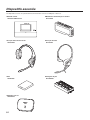
Related devices
Devices related to the wireless intercom system are listed below.
XCenter Module
WX-CC411/WX-CC412
XAll-In-One Headset
WX-CH450
XBattery
WX-B3030
XWireless Repeater
WX-CR470
20
XBelt Pack
WX-CT420
XHeadset
WX-CH427
XBattery Charger
WX-Z3040A
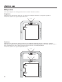
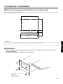
Installation procedures
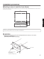
wDeciding on where to install the Center Module
Select a wall on which to mount this unit, drill a hole in it to pass the wires through, and decide where the four screws are to be
positioned, as shown below.
135
190
40
25
English
5
200
Important
p Ensure that the installation surface has the pull-out strength below.
w Installation
Mount this unit using the accessory wall mounting bracket and 4 screws (4.1
mm × 25 mm
{5/32 inches × 63/64 inches}).
[Minimum pull-out strength: 780 N {80 kJf}]
Wire channel
Screws (locally procured)
(wood screws:
4.1 mm × 25 mm
{5/32 inches × 63/64 inches})
21
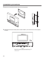
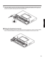
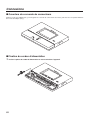
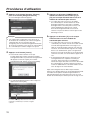
Installation procedures
Mount this unit onto the four hooks of the wall mounting bracket.
Look at the confirmation window (which is marked “CHECK”), and confirm that this unit fits properly
into place.
ロモワユチモ
ロモワユチャ
ヤワヵ ヤヰヮ ヤワヵ ヤヰヮ ヤワヵ ヤワヵ ヤヰヮ ヤワヵ ヵㄙュ ヴヨ ンㄙュ
ヒ
ビ ⿂
⿃
ュユヷリヤユ
モロユンヵ
ンヴノビピビヤ
ヷリュユヰチヰヶヵ
ヒパャモヴユノヵ
ヒパパャモヴユノヵヹ
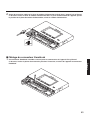
Check that the “{” marks of the wall mounting bracket are visible.
If they are not visible, this means that this unit has not been
installed properly.
22
Use the accessory clamp to secure the power cord to the wall and attach the clamp using a screw
(4.1 mm × 25 mm {5/32 inches × 63/64 inches}).
[Minimum pull-out strength: 780 N {80 kJf}]
English
Screw (locally procured)
150 mm to 200 mm
{5-15/16 inches to 7-7/8 inches}
23
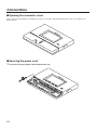
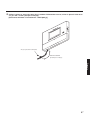
Connections
wOpening the connector cover
Press on the area indicated by and slide the connector cover down, and pull the bottom part of the cover toward you as
indicated by .
wSecuring the power cord
Insert the accessory power cord clamp into this unit.
24
Before proceeding any further, push down the position of the power cord clamp inserted into this unit,
as shown in the figure below. Insert the power cord plug into the power socket of this unit, adjust the
position of the power cord clamp, and secure the power cord.
English
wWiring the Euroblock connector
A detachable Euroblock connector is provided for this unit’s connectors. As shown in the figure below,
insert a slot-head screwdriver into the gap, and remove the Euroblock connector from this unit.
25
Connections
Connect the wires to the Euroblock connector. Using a slot-head screwdriver, loosen the Euroblock
connector screws in turn, peel off the insulating material around each of the wires, twist the conductors
firmly, insert the ends of the conductors into the Euroblock connector, and tighten the Euroblock
connector screws.
7 mm ± 1 mm
{9/32 inches ± 1/16 inches}
Note
Shaping the cables
p Recommended wires: AWG28 to 16 (Do not use soldered wires.)
p Length of insulating material to be peeled off: 7 mm ± 1 mm {9/32 inches ± 1/16 inches}
p Screw diameter: ø 2 mm {3/32 inches}
p Check that the wires have been connected securely.
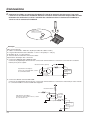
Electrical specifications of connectors
p DEVICE CNT and DEVICE COM connectors
Connect an external device between the CNT and COM connectors. These connectors are isolated from the internal
circuitry using a photo-coupler.
Internal circuitry (polar)
Max. 50 mA
CNT
Electrical specifications:
30 V control voltage, 50 mA control current
External
device
COM
Photo-coupler
p ALERT CNT and ALERT COM connectors
Connect an external device between the CNT and COM connectors. These connectors operate by a “make” action. The
COM connector is connected to the GND inside this unit.
Internal circuitry
2 mA
short
current
Electrical specifications:
DC 5 V open voltage, 2 mA short current
CNT
Photo-coupler
External
device
COM
26
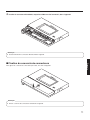
Install the Euroblock connector, to which the wires have been connected, in this unit.
English
Note
p Insert the Euroblock connector firmly into this unit.
wAttaching the connector cover
Slide the connector cover from below, and attach it to this unit.
Note
p Attach the connector cover securely to this unit.
27
Connections
wExamples of connections
Lane A
ヤワヵ ヤヰヮ ヤワヵ ヤヰヮ ヤワヵ ヤワヵ ヤヰヮ ヤワヵ ヵㄙュ ヴヨ ンㄙュ
ヒ
ビ ⿂
⿃
ュユヷリヤユ
Kitchen
microphone
Expanded
vehicle
detector
Vehicle
detector
Speaker
(8 ȍ)
ヷリュユヰチヰヶヵ
ヒパャモヴユノヵ
ヒパパャモヴユノヵヹ
ンヴノビピビヤ
External
device
Order post
Microphone
モロユンヵ
Sensors
Refrigerator
Cash register,
etc.
Kitchen monitor
HUB
Kitchen speaker
(8 ȍ)
Drive-thru lane A
Network Cameras
PC
Lane B (WX-CC412 only)
Order post
Microphone
Kitchen
microphone
Expanded
vehicle
detector
Vehicle
detector
Speaker
(8 ȍ)
Kitchen speaker
(8 ȍ)
Drive-thru lane B
PC
28
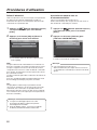
Screen operations
wBasic screen operations
This section describes basic screen operations.
For details on how to operate the unit and select its settings,
refer to the “Operating Instructions <Setup Instructions>”
(PDF file).
Note
p The LCD display is easily scratched, so always
perform the operations involving this display using
one finger.
p Do not use a ballpoint pen or other hard-tipped or
sharp object, including fingernails, to perform touch
panel operations.
p Do not press on the LCD display with too much force.
p Do not use any of the LCD protective films available
on the market. (The touch panel may not operate
properly.)
p The inside of the LCD display may become cloudy
or condensation (droplets of water) may form and
the display may not operate properly when the
temperature changes suddenly, such as immediately
after air-conditioning or heating has been turned on. If
this occurs, leave this unit for about one to two hours
before attempting to use it again.
English
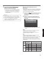
wEntering the settings
Return button
On a screen with multiple setting items, touch the [Set]
button to confirm a setting.
This button is used to return to the previous screen.
Item selector buttons
Operation moves to the screen corresponding to the
button that has been touched. On the setting screen, one
of the buttons is selected (indicated in orange).
The buttons have different names, depending on the
situation.
Page selector buttons
These buttons are used to select the page when the
screen extends over a multiple number of pages.
When the ź button is touched, the next page screen
is displayed, and when the Ÿ button is touched, the
previous page screen is displayed.
Set button
This button confirms all multiple settings displayed on the
screen together.
29
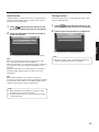
Screen operations
w Inputting characters
w Inputting the date and time
Use the keys on the keyboard to input the characters when
a password or an address is to be input.
Input the date and time—the time may involve using Daylight
Saving Time.
Input character display area
The characters that have been input are displayed.
Backspace button
Touch this button to delete the last character of the
characters shown in the input character display area.
Character input buttons
The character on the button that is touched is input.
Space button
Touch this button to input a space.
Set/Enter button [Enter/Login]
Touch this button to enter the character string that has
been input.
Setting value display area
The current setting values are displayed.
+ and – buttons
Adjust the settings by touching the + and – buttons.
Set/Enter button [Set/Enter]
Touch this button to enter the time that has been set.
Character type selector button
Touch this button to change the type of characters that
are to be input.
wAdjusting the volume level
Adjust the volume level.
Volume level display area
The current volume levels are displayed.
+ and – buttons
Adjust the levels by touching the + and – buttons.
Changes in the volume level take place in real time.
30
Operating procedures
wBasic operations
wID Registration
TALK: Talking with the customers
p To talk or page using an All-In-One Headset or Belt Pack,
its ID must be registered.
p For ID registration, set the Center Module to ID
registration mode, and proceed with the registration by
operating the All-In-One Headset or Belt Pack concerned.
This function enables two-way conversations between the
store personnel who are wearing All-In-One Headsets or
Belt Packs and the customer at the order post.
For further details on conversation methods, refer to the
Operating Instructions for the Belt Pack (WX-CT420) or AllIn-One Headset (WX-CH450).
PAGE: Talking with other store personnel
Touch
(setting button) on the touch
panel.
p The password input screen appears.
English
Store personnel who are wearing All-In-One Headsets or
Belt Packs can talk to one another without being heard by
customers.
For further details on paging methods, refer to the Operating
Instructions for the Belt Pack (WX-CT420) or All-In-One
Headset (WX-CH450).
The ID registration procedure is described below based on
an example involving an All-In-One Headset or Belt Pack
operation.
Dual drive-thru lane changeover
(WX-CC412 only)
In the case of a dual drive-thru, it is possible to talk or page
by selecting lane A or lane B.
For details on how to perform lane changeover operation,
refer to the Operating Instructions for the Belt Pack (WXCT420) or All-In-One Headset (WX-CH450).
Input the password, and touch the [Login]
button.
Default password: 12345
Important
p Change the password at regular intervals for security
purposes.
p The setting menu is displayed.
31
Operating procedures
Touch [Headsets] button, and then the [ID
Headset or Belt Pack.
p The ID registration screen appears.
p The All-In-One Headset or Belt Pack searches for a
Center Module that is in ID registration mode. The
“Connecting center module A” voice prompt will be
heard from the earphone, and the lane indicator will
blink orange.
In the case of the WX-CC412, after lane A
registration, the “Connecting center module B” voice
prompt will be heard, and the lane indicator will blink
green.
p When ID registration has been completed
successfully, the “Registration complete” voice
prompt will be heard from the earphone, and then a
voice prompt for the number of the registered All-InOne Headset or Belt Pack will be heard. The power
indicator and the lane indicator now stop blinking,
and light up.
Note
p The registered All-In-One Headset or Belt Pack numbers
are displayed in the [Registered Headsets] area. When ID
registration is completed successfully, the ID of the newly
registered All-In-One Headset or Belt Pack is added.
Touch the [Start] button.
p The following pop-up screen is displayed. You cannot
perform other operations during ID registration. To
continue ID registration, touch the [YES] button. To
stop ID registration, touch the [NO] button.
p Touch the [YES] button to start ID registration mode.
The number of the All-In-One Headset or Belt Pack
that has been registered is displayed.
Press the [POWER] button while holding down
the [T1] button and [T2] button of the All-InOne Headset or Belt Pack.
p The All-In-One Headset or Belt Pack starts up in ID
registration mode. The “ID Registration Mode” voice
prompt will be heard from the earphone, and the
power indicator will blink orange.
In ID registration mode, the buttons and indicators
have different functions from those at normal startup.
32
Press the [T1] button on the All-In-One
Registration] button.
After registrating all of the headset IDs, touch the [Stop]
button on the ID registration screen.
ID registration mode for the Center Module is exited. The
power indicator of the All-In-One Headset or Belt Pack
changes from orange to green.
Important
p When registering the IDs of a multiple number of
All-In-One Headsets or Belt Packs, register the ID
of each unit in sequence. If an attempt is made to
register the IDs of multiple units at the same time, the
IDs may not be registered correctly.
p During the ID registration process, do not turn off
the power of the All-In-One Headsets or Belt Packs
or remove their batteries. Otherwise, their IDs may
not be registered correctly. If the registration is not
proceeding smoothly, touch the [Stop] button on the
Center Module, exit ID registration mode, and then try
again.
p When ID registration fails, a “BUU-UU-UU” warning
sounds in the All-In-One Headset or Belt Pack
concerned, and then the “Failed” voice prompt is
heard. If an ID registration has failed, the ID of the
All-In-One Headset or Belt Pack will not be registered
in the Center Module, and the power indicator of the
All-In-One Headset or Belt Pack concerned will blink
in red.
p The IDs of up to 32 All-In-One Headsets or Belt Packs
can be registered in one Center Module. If an attempt
is made to register IDs for more than 32 units, the IDs
of the headsets not used for the longest time will be
automatically deleted, and then the IDs of the new
units will be registered.
p It is not possible to register the ID of a wireless
repeater while ID registration mode of the All-In-One
Headsets or Belt Packs is active.
wConvenient Functions
(Other Functions)
Auto-TALK-Lock
This function enables the All-In-One Headset or Belt Pack of
pre-determined store personnel to automatically enter talk
mode when a customer approaches the order post. (TalkLock mode)
For details on how to set Auto-Talk-Lock mode, refer to the
Operating Instructions for the Belt Pack (WX-CT420) or AllIn-One Headset (WX-CH450).
Speed Team
“Speed Team operation” refers to a mode of operation in
which, at busy times when there are more vehicles than the
lanes can accommodate, normal operation is suspended,
the vehicle detectors are shut off, and the store personnel
go directly to the customers in their vehicles to take their
orders.
Touch
(Quick Operation button) on the
touch panel, and then the [Common] button.
Touch the [ON] button for [Speed Team] to
enable Speed Team operation.
Manager mode
English
One of all the All-In-One Headsets or Belt Packs in a lane
can be set to manager mode.
The All-In-One Headset or Belt Pack in manager mode has
a higher priority than the other All-In-One Headsets or Belt
Packs, and can monopolize one of the four communication
channels.
This means that the manager can talk or page at any time.
For details on how to set manager mode, refer to the
Operating Instructions for the Belt Pack (WX-CT420) or AllIn-One Headset (WX-CH450).
p In the All-In-One Headsets or Belt Packs, the
“SPEED TEAM ON” voice prompt is heard from the
earphones.
Note
p In Speed Team mode, the “SPEED TEAM ON”
voice prompt will be heard every 5 minutes from the
earphone of the All-In-One Headsets or Belt Packs.
When the [P] button of the All-In-One Headset
or Belt Pack is pressed, conversation becomes
possible in page lock mode.
p Even if the [P] button is set to Press-to-Page, the
button will still operate in page lock.
p For further details on paging methods, refer to the
Operating Instructions for the Belt Pack (WX-CT420)
or All-In-One Headset (WX-CH450).
33
Operating procedures
To release Speed Team operation, touch the
[OFF] button for [Speed Team] on the screen in
step 2.
p In the All-In-One Headsets or Belt Packs, the
“SPEED TEAM OFF” voice prompt is heard from the
earphones, and normal operation is restored.
Note
p In Speed Team mode, it is not possible to talk with
customers at the order posts.
p When talking is attempted from an All-In-One Headset
or Belt Pack, the “Operation not allowed” voice prompt
is heard from the earphone.
Cross Beep (WX-CC412 only)
“Cross Beep” is a function that enables a beep tone to be
heard from the All-In-One Headsets or Belt Packs when a
customer approaches the order post of the other lane.
Touch
(Quick Operation button) on the
touch panel, and then touch the [Common]
button.
Touch the [ON] button for [Cross Beep] to
enable Cross Beep operation.
p To release Cross Beep, touch the [OFF] button.
OFF:
If lane A has been selected, beep tone A will be heard when
a vehicle in lane A is detected.
However, beep tone B will not be heard even when a vehicle
in lane B has been detected.
ON:
If lane A has been selected, beep tone A will be heard when
a vehicle in lane A is detected.
Furthermore, beep tone B is heard at a low volume level
even when a vehicle in lane B has been detected.
When vehicles have been detected in both lanes, beep tone
A and beep tone B, which are heard at a low volume level,
will be heard alternately.
Cross
Beep
OFF
ON
34
Vehicle detector
All-In-One Headset or Belt Pack
Lane A is Lane B is
ON
ON
{
–
A
B
–
Beep A
–
{
{
{
Beep A
Beep B
{
–
Beep A
Low level Beep A
–
{
Low level Beep B Beep B
{
{
Beep A +
Beep B +
Low level Beep B Low level Beep A
–
Beep B
V/Det Override
Talk/page release
“V/Det Override” is a function that sets the vehicle detectors
virtually to ON and keeps both the order post microphone
and speaker in the ON setting.
The talk (or page) status of an All-In-One Headset or Belt
Pack is forcibly released.
Touch
(Quick Operation button) on the
touch panel, and then touch the [Lane] button.
Touch the [ON] button for [V/Det Override] to
Touch
(Quick Operation button) on the
touch panel, and then touch the [Lane] button.
Touch the [Execute] button for [T/P Release].
enable this function.
English
p Communication is forcibly terminated.
p To release V/Det Override, touch the [OFF] button.
Note
OFF:
When the vehicle detector detects a vehicle at the order
post, a beep tone is heard from the earphone.
When the Talk button on an All-In-One Headset or Belt Pack
is pressed, the order post’s speaker and microphone are
turned on.
When the vehicle drives off, vehicle detection is turned off.
The OFF setting and Auto-Talk-Lock mode can now be
established.
p The talk (or page) status of the All-In-One Headset or
Belt Pack in manager mode is not released.
ON:
When [V/Det Override] is set to ON, the order post’s
microphone is turned on permanently and talking is enabled
even when the vehicle detector is not ON. (Sound from the
order post’s microphone can be forcibly heard.)
Note
p When Speed Team is enabled, the setting for V/Det
Override is automatically turned OFF.
p In Speed Team mode, you cannot change the setting
for V/Det Override.
35
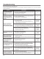
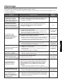
Troubleshooting
Check the following before requesting repair.
Consult your sales shop if these measures do not resolve a problem, if symptoms not listed here occur, or if you have a question
related to engineering.
Symptom
Cause/solution
Reference pages
No communication between
the order post, Belt Packs
and All-In-One Headsets is
possible.
p Is the power cord connected securely to the AC input terminal
of this unit and to the power outlet?
¬ Check whether it is connected.
P.24
Paging between the store
personnel is possible, but
talking with the customers
using the order post is not
possible.
p Have the microphone input and speaker output of the order
post been connected properly?
¬Check whether it is connected properly.
P.25
p The speaker and microphone for the order post may not have
been installed correctly.
¬ Check that the speaker and microphone are placed at a
sufficient distance from each other, and anchor them securely
so that any vibrations are absorbed.
WX-CS460
Operating
Instructions
p The input and output audio levels may have been set too high.
¬ Lower the audio input and output levels (OUT MIC/OUT SP) for
the order post to the appropriate level. (Feedback noise can be
prevented by selecting a setting that lowers the audio input level.)
Operating
Instructions
<Setup
Instructions>
p The echo canceller is off or its level is low.
¬ Set the echo canceller to the appropriate level.
(The default setting is “MID”.)
Operating
Instructions
<Setup
Instructions>
A lot of noise is heard from
order post.
p DNR is OFF or its level may be low.
¬ Set the DNR to the appropriate level.
(The default setting is “MID”.)
Operating
Instructions
<Setup
Instructions>
There is no reaction even
when the buttons on the
touch panel are touched.
p Is the touch panel dirty?
¬ Clean the touch panel.
If there is no improvement even after it has been cleaned, adjust
the touch panel.
When one of the buttons on
the touch panel has been
touched, another button
reacts instead.
p The touch panel must be adjusted.
¬ Adjust the touch panel.
Communication breaks up or
it is hardly possible to hear
what is being said.
p Are the All-In-One Headsets or Belt Packs too far away from
the Center Module, or are there any obstructions such as
concrete walls or metal devices between the Center Module
and the All-In-One Headsets or Belt Packs?
¬ Contact the store where you purchased this unit, and move this
unit to a location where there are no obstructions around it.
–––
No communication with the
cameras is possible.
p Have the cameras been registered in the Center Module?
¬ No communication with the cameras is possible if the cameras
have not been registered. Register the cameras that are to be
connected.
Operating
Instructions
<Browser Guide>
Nothing happens even when
operations are performed
correctly; or the operations
are performing incorrectly.
p This unit may not be working properly.
¬ Press the reset button on the side panel of this unit using a finetipped object. (The settings, etc. will not be cleared.)
An echo is heard from the
earphone of the headset
when an individual is talking
into the headset microphone.
36
P.10
Operating
Instructions
<Setup
Instructions>
P.13
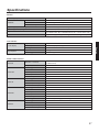
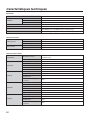
Specifications
General
Operating frequency
POWER
1921.536 MHz to 1928.448 MHz
Power source
AC 100 V to 120 V 50 Hz/60 Hz
Connector
Universal Type with an 3 pins AC Inlet
Power consumption
17 W
Operating temperature range
–10 °C to +50 °C {14 °F to 122 °F}
Operating humidity range
20 % to 90 % (no condensation)
Dimensions
375 mm (W) × 275 mm (H) × 50 mm (D)
{14-49/64 inches (W) × 10-53/64 inches (H) × 1-31/32 inches (D)}
Mass
Approx 1.9 kJ {4.2 lbs.} (Excluding the wall mounting bracket)
User Interface
LCD display
7 Type
Effective pixels
WVGA: 800 (H) × 480 (V)
Back light
LED
Type
7.8 Type
Technology
Resistive type
Number of channels
1 (WX-CC411)
2 (WX-CC412)
Frequency characteristic
300 Hz to 3 kHz
Technology
Electric balanced
Connector
Euroblock connector (HOT/COLD/GND)
Input impedance
1.5 kȍ
Rated input
–70 dBV
Maximum input
–38 dBV
Technology
Balanced
English
Touch panel
Type
Audio & Video Interface
General
OUT MIC
OUT SP
AUX MIC
AUX SP
Connector
Euroblock connector
Rated output for amplifier
2W
Conformed load impedance
8ȍ
Technology
Electric balanced
Connector
Euroblock connector (HOT/COLD/GND/PTT/COM)
Input impedance
3 kȍ
Rated input
–67 dBV
Maximum input
–44 dBV
Control signal
PTT, Make (No voltage) when talking
Technology
Balanced
Connector
Euroblock connector
Rated output for amplifier
2W
Conformed load impedance
8ȍ
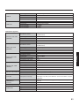
37
Specifications
LINE IN
LINE OUT
Technology
Unbalanced, Mono
Connector
Euroblock connector
Rated input
–10 dBV
Maximum input
+6 dBV
Technology
Unbalanced, Mono
Connector
Euroblock connector
Rated output
–14 dBV
Maximum output
+6 dBV
Number of channels
1 (WX-CC411)
2 (WX-CC412)
Technology
Photo-coupler
Open voltage
5V
Short current
2 mA
Connector
Euroblock connector
Number of channels
2 (WX-CC411)
4 (WX-CC412)
Technology
Photo-coupler
Open voltage
5V
Short current
2 mA
Connector
Euroblock connector
Number of channels
4
Technology
Photo-coupler
Open voltage
5V
Device Interface
AUX MIC CNT, COM
(INPUT)
VDET CNT, COM
(INPUT)
ALERT CNT, COM
(INPUT)
Short current
2 mA
Connector
Euroblock connector
Number of channels
1
Technology
Photo-coupler
Control voltage
DC 30 V
Control current
MAX 50 mA
Connector
Euroblock connector
Communication system
Asynchronous (full duplex)
Baud rate
19200 bps
SD card
Corresponding card
SD card, SDHC card
Note: miniSD card and MicroSD card are not applicable.
10BASE-T,
100BASE-TX
(Network)
Type
10/100BASE-TX (Full/Half, Auto/Man)
Connector
RJ-45
DEVICE CNT, COM
(OUTPUT)
RS-232C TxD, RxD, SG
Supported protocols
VIDEO OUT
38
IPv4: TCP/IP, HTTP, HTTPS, DHCP, DNS, SMTP, NTP, UPnP, POP
Type
NTSC
Output signals
Composite
Connector
RCA pin jack
Licenses
This unit contains thttpd, NetBSD, OpenSSL Project, Arcfour and MD5 message-digest algorithm software licensed by third
parties, and use of this software has been granted under the conditions stated below.
LICENSE ISSUES
This product uses some parts of thttpd, NetBSD, OpenSSL Project, Arcfour, MD5 message-digest algorithm.
The use of parts described above are licensed under the conditions below.
«thttpd»
Copyright 1995,1998,1999, 2000 by Jef Poskanzer <[email protected]>. All rights reserved.
Redistribution and use in source and binary forms, with or without modification, are permitted provided that the following
conditions are met:
1. Redistributions of source code must retain the above copyright notice, this list of conditions and the following disclaimer.
2. Redistributions in binary form must reproduce the above copyright notice, this list of conditions and the following disclaimer in
the documentation and/or other materials provided with the distribution.
«NetBSD»
<isys_fcntl.h>
Copyright (c) 1983, 1990, 1993 The Regents of the University of California. All rights reserved.
(c) UNIX System Laboratories, Inc.
All or some portions of this file are derived from material licensed to the University of California by American Telephone and
Telegraph Co. or Unix System Laboratories, Inc. and are reproduced herein with the permission of UNIX System Laboratories,
Inc.
Redistribution and use in source and binary forms, with or without modification, are permitted provided that the following
conditions are met:
1. Redistributions of source code must retain the above copyright notice, this list of conditions and the following disclaimer.
2. Redistributions in binary form must reproduce the above copyright notice, this list of conditions and the following disclaimer in
the documentation and/or other materials provided with the distribution.
3. All advertising materials mentioning features or use of this software must display the following acknowledgement:
This product includes software developed by the University of California, Berkeley and its contributors.
4. Neither the name of the University nor the names of its contributors may be used to endorse or promote products derived
from this software without specific prior written permission.
THIS SOFTWARE IS PROVIDED BY THE REGENTS AND CONTRIBUTORS ''AS IS'' AND ANY EXPRESS OR IMPLIED
WARRANTIES, INCLUDING, BUT NOT LIMITED TO, THE IMPLIED WARRANTIES OF MERCHANTABILITY AND FITNESS
FOR A PARTICULAR PURPOSE ARE DISCLAIMED. IN NO EVENT SHALL THE REGENTS OR CONTRIBUTORS BE LIABLE
FOR ANY DIRECT, INDIRECT, INCIDENTAL, SPECIAL, EXEMPLARY, OR CONSEQUENTIAL DAMAGES (INCLUDING, BUT
NOT LIMITED TO, PROCUREMENT OF SUBSTITUTE GOODS OR SERVICES; LOSS OF USE, DATA, OR PROFITS; OR
BUSINESS INTERRUPTION)
HOWEVER CAUSED AND ON ANY THEORY OF LIABILITY, WHETHER IN CONTRACT, STRICT LIABILITY, OR TORT
(INCLUDING NEGLIGENCE OR OTHERWISE) ARISING IN ANY WAY OUT OF THE USE OF THIS SOFTWARE, EVEN IF
ADVISED OF THE POSSIBILITY OF SUCH DAMAGE.
@(#)fcntl.h
8.3 (Berkeley) 1/21/94
39
English
THIS SOFTWARE IS PROVIDED BY THE AUTHOR AND CONTRIBUTORS ''AS IS'' AND ANY EXPRESS OR IMPLIED
WARRANTIES, INCLUDING, BUT NOT LIMITED TO, THE IMPLIED WARRANTIES OF MERCHANTABILITY AND FITNESS
FOR A PARTICULAR PURPOSE ARE DISCLAIMED. IN NO EVENT SHALL THE AUTHOR OR CONTRIBUTORS BE LIABLE
FOR ANY DIRECT, INDIRECT, INCIDENTAL, SPECIAL, EXEMPLARY, OR CONSEQUENTIAL DAMAGES (INCLUDING, BUT
NOT LIMITED TO, PROCUREMENT OF SUBSTITUTE GOODS OR SERVICES; LOSS OF USE, DATA, OR PROFITS; OR
BUSINESS INTERRUPTION)
HOWEVER CAUSED AND ON ANY THEORY OF LIABILITY, WHETHER IN CONTRACT, STRICT LIABILITY, OR TORT
(INCLUDING NEGLIGENCE OR OTHERWISE) ARISING IN ANY WAY OUT OF THE USE OF THIS SOFTWARE, EVEN IF
ADVISED OF THE POSSIBILITY OF SUCH DAMAGE.
Licenses
< isys_pl_stdio.c >
Copyright (c) 1990 The Regents of the University of California. All rights reserved.
This code is derived from software contributed to Berkeley by Chris Torek.
Redistribution and use in source and binary forms, with or without modification, are permitted provided that the following
conditions are met:
1. Redistributions of source code must retain the above copyright notice, this list of conditions and the following disclaimer.
2. Redistributions in binary form must reproduce the above copyright notice, this list of conditions and the following disclaimer in
the documentation and/or other materials provided with the distribution.
3. Neither the name of the University nor the names of its contributors may be used to endorse or promote products derived
from this software without specific prior written permission.
THIS SOFTWARE IS PROVIDED BY THE REGENTS AND CONTRIBUTORS ''AS IS'' AND ANY EXPRESS OR IMPLIED
WARRANTIES, INCLUDING, BUT NOT LIMITED TO, THE IMPLIED WARRANTIES OF MERCHANTABILITY AND FITNESS
FOR A PARTICULAR PURPOSE ARE DISCLAIMED. IN NO EVENT SHALL THE REGENTS OR CONTRIBUTORS BE LIABLE
FOR ANY DIRECT, INDIRECT, INCIDENTAL, SPECIAL, EXEMPLARY, OR CONSEQUENTIAL DAMAGES (INCLUDING, BUT
NOT LIMITED TO, PROCUREMENT OF SUBSTITUTE GOODS OR SERVICES; LOSS OF USE, DATA, OR PROFITS; OR
BUSINESS INTERRUPTION)
HOWEVER CAUSED AND ON ANY THEORY OF LIABILITY, WHETHER IN CONTRACT, STRICT LIABILITY, OR TORT
(INCLUDING NEGLIGENCE OR OTHERWISE) ARISING IN ANY WAY OUT OF THE USE OF THIS SOFTWARE, EVEN IF
ADVISED OF THE POSSIBILITY OF SUCH DAMAGE.
<isys_getopt.c>
Copyright (c) 1987, 1993, 1994 The Regents of the University of California. All rights reserved.
Redistribution and use in source and binary forms, with or without modification, are permitted provided that the following
conditions are met:
1. Redistributions of source code must retain the above copyright notice, this list of conditions and the following disclaimer.
2. Redistributions in binary form must reproduce the above copyright notice, this list of conditions and the following disclaimer in
the documentation and/or other materials provided with the distribution.
3. All advertising materials mentioning features or use of this software must display the following acknowledgement:
This product includes software developed by the University of California, Berkeley and its contributors.
4. Neither the name of the University nor the names of its contributors may be used to endorse or promote products derived
from this software without specific prior written permission.
THIS SOFTWARE IS PROVIDED BY THE REGENTS AND CONTRIBUTORS ''AS IS'' AND ANY EXPRESS OR IMPLIED
WARRANTIES, INCLUDING, BUT NOT LIMITED TO, THE IMPLIED WARRANTIES OF MERCHANTABILITY AND FITNESS
FOR A PARTICULAR PURPOSE ARE DISCLAIMED. IN NO EVENT SHALL THE REGENTS OR CONTRIBUTORS BE LIABLE
FOR ANY DIRECT, INDIRECT, INCIDENTAL, SPECIAL, EXEMPLARY, OR CONSEQUENTIAL DAMAGES (INCLUDING, BUT
NOT LIMITED TO, PROCUREMENT OF SUBSTITUTE GOODS OR SERVICES; LOSS OF USE, DATA, OR PROFITS; OR
BUSINESS INTERRUPTION)
HOWEVER CAUSED AND ON ANY THEORY OF LIABILITY, WHETHER IN CONTRACT, STRICT LIABILITY, OR TORT
(INCLUDING NEGLIGENCE OR OTHERWISE) ARISING IN ANY WAY OUT OF THE USE OF THIS SOFTWARE, EVEN IF
ADVISED OF THE POSSIBILITY OF SUCH DAMAGE.
<isys_pl_crypt .c >
Copyright (c) 1989 The Regents of the University of California. All rights reserved.
This code is derived from software contributed to Berkeley by Tom Truscott.
Redistribution and use in source and binary forms, with or without modification, are permitted provided that the following
conditions are met:
1. Redistributions of source code must retain the above copyright notice, this list of conditions and the following disclaimer.
2. Redistributions in binary form must reproduce the above copyright notice, this list of conditions and the following disclaimer in
the documentation and/or other materials provided with the distribution.
3. All advertising materials mentioning features or use of this software must display the following acknowledgement:
This product includes software developed by the University of California, Berkeley and its contributors.
4. Neither the name of the University nor the names of its contributors may be used to endorse or promote products derived
from this software without specific prior written permission.
40
THIS SOFTWARE IS PROVIDED BY THE REGENTS AND CONTRIBUTORS ''AS IS'' AND ANY EXPRESS OR IMPLIED
WARRANTIES, INCLUDING, BUT NOT LIMITED TO, THE IMPLIED WARRANTIES OF MERCHANTABILITY AND FITNESS
FOR A PARTICULAR PURPOSE ARE DISCLAIMED. IN NO EVENT SHALL THE REGENTS OR CONTRIBUTORS BE LIABLE
FOR ANY DIRECT, INDIRECT, INCIDENTAL, SPECIAL, EXEMPLARY, OR CONSEQUENTIAL DAMAGES (INCLUDING, BUT
NOT LIMITED TO, PROCUREMENT OF SUBSTITUTE GOODS OR SERVICES; LOSS OF USE, DATA, OR PROFITS; OR
BUSINESS INTERRUPTION)
HOWEVER CAUSED AND ON ANY THEORY OF LIABILITY, WHETHER IN CONTRACT, STRICT LIABILITY, OR TORT
(INCLUDING NEGLIGENCE OR OTHERWISE) ARISING IN ANY WAY OUT OF THE USE OF THIS SOFTWARE, EVEN IF
ADVISED OF THE POSSIBILITY OF SUCH DAMAGE.
<isys_vsscanf.c>
Copyright (c) 1990, 1993 The Regents of the University of California. All rights reserved.
This code is derived from software contributed to Berkeley by Chris Torek.
THIS SOFTWARE IS PROVIDED BY THE REGENTS AND CONTRIBUTORS ''AS IS'' AND ANY EXPRESS OR IMPLIED
WARRANTIES, INCLUDING, BUT NOT LIMITED TO, THE IMPLIED WARRANTIES OF MERCHANTABILITY AND FITNESS
FOR A PARTICULAR PURPOSE ARE DISCLAIMED. IN NO EVENT SHALL THE REGENTS OR CONTRIBUTORS BE LIABLE
FOR ANY DIRECT, INDIRECT, INCIDENTAL, SPECIAL, EXEMPLARY, OR CONSEQUENTIAL DAMAGES (INCLUDING, BUT
NOT LIMITED TO, PROCUREMENT OF SUBSTITUTE GOODS OR SERVICES; LOSS OF USE, DATA, OR PROFITS; OR
BUSINESS INTERRUPTION)
HOWEVER CAUSED AND ON ANY THEORY OF LIABILITY, WHETHER IN CONTRACT, STRICT LIABILITY, OR TORT
(INCLUDING NEGLIGENCE OR OTHERWISE) ARISING IN ANY WAY OUT OF THE USE OF THIS SOFTWARE, EVEN IF
ADVISED OF THE POSSIBILITY OF SUCH DAMAGE.
<nce_util_strtol.c>
Copyright (c) 1990, 1993 The Regents of the University of California. All rights reserved.
Redistribution and use in source and binary forms, with or without modification, are permitted provided that the following
conditions are met:
1. Redistributions of source code must retain the above copyright notice, this list of conditions and the following disclaimer.
2. Redistributions in binary form must reproduce the above copyright notice, this list of conditions and the following disclaimer in
the documentation and/or other materials provided with the distribution.
3. All advertising materials mentioning features or use of this software must display the following acknowledgement:
This product includes software developed by the University of California, Berkeley and its contributors.
4. Neither the name of the University nor the names of its contributors may be used to endorse or promote products derived
from this software without specific prior written permission.
THIS SOFTWARE IS PROVIDED BY THE REGENTS AND CONTRIBUTORS ''AS IS'' AND ANY EXPRESS OR IMPLIED
WARRANTIES, INCLUDING, BUT NOT LIMITED TO, THE IMPLIED WARRANTIES OF MERCHANTABILITY AND FITNESS
FOR A PARTICULAR PURPOSE ARE DISCLAIMED. IN NO EVENT SHALL THE REGENTS OR CONTRIBUTORS BE LIABLE
FOR ANY DIRECT, INDIRECT, INCIDENTAL, SPECIAL, EXEMPLARY, OR CONSEQUENTIAL DAMAGES (INCLUDING, BUT
NOT LIMITED TO, PROCUREMENT OF SUBSTITUTE GOODS OR SERVICES; LOSS OF USE, DATA, OR PROFITS; OR
BUSINESS INTERRUPTION)
HOWEVER CAUSED AND ON ANY THEORY OF LIABILITY, WHETHER IN CONTRACT, STRICT LIABILITY, OR TORT
(INCLUDING NEGLIGENCE OR OTHERWISE) ARISING IN ANY WAY OUT OF THE USE OF THIS SOFTWARE, EVEN IF
ADVISED OF THE POSSIBILITY OF SUCH DAMAGE.
Parts of the NetBSD Kernel are provided with the licenses that are slightly different from the above Berkeley-formed license.
Please refer the source code of the NetBSD Kernel about the details.
The source code of the NetBSD Kernel is provided by the NetBSD CVS Repositories (http://cvsweb.netbsd.org/bsdweb.cgi/),
and this product includes parts of the source code in the following directories.
http://cvsweb.netbsd.org/bsdweb.cgi/src/sys/kern/
http://cvsweb.netbsd.org/bsdweb.cgi/src/sys/net/
http://cvsweb.netbsd.org/bsdweb.cgi/src/sys/netinet/
41
English
Redistribution and use in source and binary forms, with or without modification, are permitted provided that the following
conditions are met:
1. Redistributions of source code must retain the above copyright notice, this list of conditions and the following disclaimer.
2. Redistributions in binary form must reproduce the above copyright notice, this list of conditions and the following disclaimer in
the documentation and/or other materials provided with the distribution.
3. Neither the name of the University nor the names of its contributors may be used to endorse or promote products derived
from this software without specific prior written permission.
Licenses
«OpenSSL»
This product includes software developed by the OpenSSL Project for use in the OpenSSL Toolkit (http://www.openssl.org/).
< md32_common.h>
Copyright (c) 1999-2002 The OpenSSL Project. All rights reserved.
Redistribution and use in source and binary forms, with or without modification, are permitted provided that the following
conditions are met:
1. Redistributions of source code must retain the above copyright notice, this list of conditions and the following disclaimer.
2. Redistributions in binary form must reproduce the above copyright notice, this list of conditions and the following disclaimer in
the documentation and/or other materials provided with the distribution.
3. All advertising materials mentioning features or use of this software must display the following acknowledgment:
"This product includes software developed by the OpenSSL Project for use in the OpenSSL Toolkit. (http://www.OpenSSL.
org/)"
4. The names "OpenSSL Toolkit" and "OpenSSL Project" must not be used to endorse or promote products derived from this
software without prior written permission. For written permission, please contact [email protected].
5. Products derived from this software may not be called "OpenSSL" nor may "OpenSSL" appear in their names without prior
written permission of the OpenSSL Project.
6. Redistributions of any form whatsoever must retain the following acknowledgment:
"This product includes software developed by the OpenSSL Project for use in the OpenSSL Toolkit (http://www.OpenSSL.
org/)"
THIS SOFTWARE IS PROVIDED BY THE OpenSSL PROJECT ''AS IS'' AND ANY EXPRESSED OR IMPLIED WARRANTIES,
INCLUDING, BUT NOT LIMITED TO, THE IMPLIED WARRANTIES OF MERCHANTABILITY AND FITNESS FOR A
PARTICULAR PURPOSE ARE DISCLAIMED. IN NO EVENT SHALL THE OpenSSL PROJECT OR ITS CONTRIBUTORS
BE LIABLE FOR ANY DIRECT, INDIRECT, INCIDENTAL, SPECIAL, EXEMPLARY, OR CONSEQUENTIAL DAMAGES
(INCLUDING, BUT NOT LIMITED TO, PROCUREMENT OF SUBSTITUTE GOODS OR SERVICES; LOSS OF USE, DATA,
OR PROFITS; OR BUSINESS INTERRUPTION) HOWEVER CAUSED AND ON ANY THEORY OF LIABILITY, WHETHER IN
CONTRACT, STRICT LIABILITY, OR TORT (INCLUDING NEGLIGENCE OR OTHERWISE) ARISING IN ANY WAY OUT OF
THE USE OF THIS SOFTWARE, EVEN IF ADVISED OF THE POSSIBILITY OF SUCH DAMAGE.
This product includes cryptographic software written by Eric Young ([email protected]). This product includes software written
by Tim Hudson ([email protected]).
<md5_locl.h>
Copyright (C) 1995-1998 Eric Young ([email protected]) All rights reserved.
This package is an SSL implementation written by Eric Young ([email protected]).
The implementation was written so as to conform with Netscapes SSL.
This library is free for commercial and non-commercial use as long as the following conditions are aheared to. The following
conditions apply to all code found in this distribution, be it the RC4, RSA, lhash, DES, etc., code; not just the SSL code. The
SSL documentation included with this distribution is covered by the same copyright terms except that the holder is Tim Hudson
([email protected]).
Copyright remains Eric Young's, and as such any Copyright notices in the code are not to be removed.
If this package is used in a product, Eric Young should be given attribution as the author of the parts of the library used.
This can be in the form of a textual message at program startup or in documentation (online or textual) provided with the
package.
Redistribution and use in source and binary forms, with or without modification, are permitted provided that the following
conditions are met:
1. Redistributions of source code must retain the copyright notice, this list of conditions and the following disclaimer.
2. Redistributions in binary form must reproduce the above copyright notice, this list of conditions and the following disclaimer in
the documentation and/or other materials provided with the distribution.
3. All advertising materials mentioning features or use of this software must display the following acknowledgement:
"This product includes cryptographic software written by Eric Young ([email protected])"
The word 'cryptographic' can be left out if the rouines from the library being used are not cryptographic related :-).
4. If you include any Windows specific code (or a derivative thereof) from the apps directory (application code) you must include
an acknowledgement:
"This product includes software written by Tim Hudson ([email protected])"
42
THIS SOFTWARE IS PROVIDED BY ERIC YOUNG ''AS IS'' AND ANY EXPRESS OR IMPLIED WARRANTIES, INCLUDING,
BUT NOT LIMITED TO, THE IMPLIED WARRANTIES OF MERCHANTABILITY AND FITNESS FOR A PARTICULAR
PURPOSE ARE DISCLAIMED. IN NO EVENT SHALL THE AUTHOR OR CONTRIBUTORS BE LIABLE FOR ANY DIRECT,
INDIRECT, INCIDENTAL, SPECIAL, EXEMPLARY, OR CONSEQUENTIAL DAMAGES (INCLUDING, BUT NOT LIMITED
TO, PROCUREMENT OF SUBSTITUTE GOODS OR SERVICES; LOSS OF USE, DATA, OR PROFITS; OR BUSINESS
INTERRUPTION)
HOWEVER CAUSED AND ON ANY THEORY OF LIABILITY, WHETHER IN CONTRACT, STRICT LIABILITY, OR TORT
(INCLUDING NEGLIGENCE OR OTHERWISE) ARISING IN ANY WAY OUT OF THE USE OF THIS SOFTWARE, EVEN IF
ADVISED OF THE POSSIBILITY OF SUCH DAMAGE.
The licence and distribution terms for any publically available version or derivative of this code cannot be changed. i.e. this code
cannot simply be copied and put under another distribution licence [including the GNU Public Licence.]
<md5.h>
Copyright (C) 1995-1998 Eric Young ([email protected]) All rights reserved.
Copyright remains Eric Young's, and as such any Copyright notices in the code are not to be removed.
If this package is used in a product, Eric Young should be given attribution as the author of the parts of the library used.
This can be in the form of a textual message at program startup or in documentation (online or textual) provided with the
package.
Redistribution and use in source and binary forms, with or without modification, are permitted provided that the following
conditions are met:
1. Redistributions of source code must retain the copyright notice, this list of conditions and the following disclaimer.
2. Redistributions in binary form must reproduce the above copyright notice, this list of conditions and the following disclaimer in
the documentation and/or other materials provided with the distribution.
3. All advertising materials mentioning features or use of this software must display the following acknowledgement:
"This product includes cryptographic software written by Eric Young ([email protected])"
The word 'cryptographic' can be left out if the rouines from the library being used are not cryptographic related :-).
4. If you include any Windows specific code (or a derivative thereof) from the apps directory (application code) you must include
an acknowledgement:
"This product includes software written by Tim Hudson ([email protected])"
THIS SOFTWARE IS PROVIDED BY ERIC YOUNG ''AS IS'' AND ANY EXPRESS OR IMPLIED WARRANTIES, INCLUDING,
BUT NOT LIMITED TO, THE IMPLIED WARRANTIES OF MERCHANTABILITY AND FITNESS FOR A PARTICULAR
PURPOSE ARE DISCLAIMED. IN NO EVENT SHALL THE AUTHOR OR CONTRIBUTORS BE LIABLE FOR ANY DIRECT,
INDIRECT, INCIDENTAL, SPECIAL, EXEMPLARY, OR CONSEQUENTIAL DAMAGES (INCLUDING, BUT NOT LIMITED
TO, PROCUREMENT OF SUBSTITUTE GOODS OR SERVICES; LOSS OF USE, DATA, OR PROFITS; OR BUSINESS
INTERRUPTION)
HOWEVER CAUSED AND ON ANY THEORY OF LIABILITY, WHETHER IN CONTRACT, STRICT LIABILITY, OR TORT
(INCLUDING NEGLIGENCE OR OTHERWISE) ARISING IN ANY WAY OUT OF THE USE OF THIS SOFTWARE, EVEN IF
ADVISED OF THE POSSIBILITY OF SUCH DAMAGE.
The licence and distribution terms for any publically available version or derivative of this code cannot be changed. i.e. this code
cannot simply be copied and put under another distribution licence [including the GNU Public Licence.]
<md5_dgst.c>
Copyright (C) 1995-1998 Eric Young ([email protected]) All rights reserved.
This package is an SSL implementation written by Eric Young ([email protected]).
The implementation was written so as to conform with Netscapes SSL.
This library is free for commercial and non-commercial use as long as the following conditions are aheared to. The following
conditions apply to all code found in this distribution, be it the RC4, RSA, lhash, DES, etc., code; not just the SSL code. The SSL
documentation included with this distribution is covered by the same copyright terms except that the holder is Tim Hudson (tjh@
cryptsoft.com).
43
English
This package is an SSL implementation written by Eric Young ([email protected]).
The implementation was written so as to conform with Netscapes SSL.
This library is free for commercial and non-commercial use as long as the following conditions are aheared to. The following
conditions apply to all code found in this distribution, be it the RC4, RSA, lhash, DES, etc., code; not just the SSL code. The
SSL documentation included with this distribution is covered by the same copyright terms except that the holder is Tim Hudson
([email protected]).
Licenses
Copyright remains Eric Young's, and as such any Copyright notices in the code are not to be removed.
If this package is used in a product, Eric Young should be given attribution as the author of the parts of the library used.
This can be in the form of a textual message at program startup or in documentation (online or textual) provided with the
package.
Redistribution and use in source and binary forms, with or without modification, are permitted provided that the following
conditions are met:
1. Redistributions of source code must retain the copyright notice, this list of conditions and the following disclaimer.
2. Redistributions in binary form must reproduce the above copyright notice, this list of conditions and the following disclaimer in
the documentation and/or other materials provided with the distribution.
3. All advertising materials mentioning features or use of this software must display the following acknowledgement:
"This product includes cryptographic software written by Eric Young ([email protected])"
The word 'cryptographic' can be left out if the rouines from the library being used are not cryptographic related :-).
4. If you include any Windows specific code (or a derivative thereof) from the apps directory (application code) you must include
an acknowledgement:
"This product includes software written by Tim Hudson ([email protected])"
THIS SOFTWARE IS PROVIDED BY ERIC YOUNG ''AS IS'' AND ANY EXPRESS OR IMPLIED WARRANTIES, INCLUDING,
BUT NOT LIMITED TO, THE IMPLIED WARRANTIES OF MERCHANTABILITY AND FITNESS FOR A PARTICULAR
PURPOSE ARE DISCLAIMED. IN NO EVENT SHALL THE AUTHOR OR CONTRIBUTORS BE LIABLE FOR ANY DIRECT,
INDIRECT, INCIDENTAL, SPECIAL, EXEMPLARY, OR CONSEQUENTIAL DAMAGES (INCLUDING, BUT NOT LIMITED
TO, PROCUREMENT OF SUBSTITUTE GOODS OR SERVICES; LOSS OF USE, DATA, OR PROFITS; OR BUSINESS
INTERRUPTION)
HOWEVER CAUSED AND ON ANY THEORY OF LIABILITY, WHETHER IN CONTRACT, STRICT LIABILITY, OR TORT
(INCLUDING NEGLIGENCE OR OTHERWISE) ARISING IN ANY WAY OUT OF THE USE OF THIS SOFTWARE, EVEN IF
ADVISED OF THE POSSIBILITY OF SUCH DAMAGE.
The licence and distribution terms for any publically available version or derivative of this code cannot be changed. i.e. this code
cannot simply be copied and put under another distribution licence [including the GNU Public Licence.]
<e_os2.h>
Copyright (c) 1998-2000 The OpenSSL Project. All rights reserved.
Redistribution and use in source and binary forms, with or without modification, are permitted provided that the following
conditions are met:
1. Redistributions of source code must retain the above copyright notice, this list of conditions and the following disclaimer.
2. Redistributions in binary form must reproduce the above copyright notice, this list of conditions and the following disclaimer in
the documentation and/or other materials provided with the distribution.
3. All advertising materials mentioning features or use of this software must display the following acknowledgment:
"This product includes software developed by the OpenSSL Project for use in the OpenSSL Toolkit. (http://www.openssl.org/)"
4. The names "OpenSSL Toolkit" and "OpenSSL Project" must not be used to endorse or promote products derived from this
software without prior written permission. For written permission, please contact [email protected].
5. Products derived from this software may not be called "OpenSSL" nor may "OpenSSL" appear in their names without prior
written permission of the OpenSSL Project.
6. Redistributions of any form whatsoever must retain the following acknowledgment:
"This product includes software developed by the OpenSSL Project for use in the OpenSSL Toolkit (http://www.openssl.org/)"
THIS SOFTWARE IS PROVIDED BY THE OpenSSL PROJECT ''AS IS'' AND ANY EXPRESSED OR IMPLIED WARRANTIES,
INCLUDING, BUT NOT LIMITED TO, THE IMPLIED WARRANTIES OF MERCHANTABILITY AND FITNESS FOR A
PARTICULAR PURPOSE ARE DISCLAIMED. IN NO EVENT SHALL THE OpenSSL PROJECT OR ITS CONTRIBUTORS
BE LIABLE FOR ANY DIRECT, INDIRECT, INCIDENTAL, SPECIAL, EXEMPLARY, OR CONSEQUENTIAL DAMAGES
(INCLUDING, BUT NOT LIMITED TO, PROCUREMENT OF SUBSTITUTE GOODS OR SERVICES; LOSS OF USE, DATA, OR
PROFITS; OR BUSINESS INTERRUPTION)
HOWEVER CAUSED AND ON ANY THEORY OF LIABILITY, WHETHER IN CONTRACT, STRICT LIABILITY, OR TORT
(INCLUDING NEGLIGENCE OR OTHERWISE) ARISING IN ANY WAY OUT OF THE USE OF THIS SOFTWARE, EVEN IF
ADVISED OF THE POSSIBILITY OF SUCH DAMAGE.
This product includes cryptographic software written by Eric Young ([email protected]).
This product includes software written by Tim Hudson ([email protected]).
44
Arcfour
Copyright (c) April 29, 1997 Kalle Kaukonen. All Rights Reserved.
Redistribution and use in source and binary forms, with or without modification, are permitted provided that this copyright notice
and disclaimer are retained.
THIS SOFTWARE IS PROVIDED BY KALLE KAUKONEN AND CONTRIBUTORS ''AS IS'' AND ANY EXPRESS OR
IMPLIED WARRANTIES, INCLUDING, BUT NOT LIMITED TO, THE IMPLIED WARRANTIES OF MERCHANTABILITY
AND FITNESS FOR A PARTICULAR PURPOSE ARE DISCLAIMED. IN NO EVENT SHALL KALLE KAUKONEN OR
CONTRIBUTORS BE LIABLE FOR ANY DIRECT, INDIRECT, INCIDENTAL, SPECIAL, EXEMPLARY, OR CONSEQUENTIAL
DAMAGES (INCLUDING, BUT NOT LIMITED TO, PROCUREMENT OF SUBSTITUTE GOODS OR SERVICES; LOSS OF
USE, DATA, OR PROFITS; OR BUSINESS INTERRUPTION)
HOWEVER CAUSED AND ON ANY THEORY OF LIABILITY, WHETHER IN CONTRACT, STRICT LIABILITY, OR TORT
(INCLUDING NEGLIGENCE OR OTHERWISE) ARISING IN ANY WAY OUT OF THE USE OF THIS SOFTWARE, EVEN IF
ADVISED OF THE POSSIBILITY OF SUCH DAMAGE.
MD5 Message-Digest Algorithm
License to copy and use this software is granted provided that it is identified as the "RSA Data Security, Inc. MD5 MessageDigest Algorithm" in all material mentioning or referencing this software or this function.
License is also granted to make and use derivative works provided that such works are identified as "derived from the RSA Data
Security, Inc. MD5 Message-Digest Algorithm" in all material mentioning or referencing the derived work.
RSA Data Security, Inc. makes no representations concerning either the merchantability of this software or the suitability of this
software for any particular purpose.
It is provided "as is" without express or implied warranty of any kind.
These notices must be retained in any copies of any part of this documentation and/or software.
45
English
MD5C.C - RSA Data Security, Inc., MD5 message-digest algorithm Copyright (C) 1991-2, RSA Data Security, Inc. Created 1991.
All rights reserved.
VERSION FRANÇAISE
(FRENCH VERSION)
Consignes de sécurité
DÉCLARATION DE LA COMMISSION FÉDÉRALE DES TÉLÉCOMMUNICATIONS (FCC)
SUR LES INTERFÉRENCES
Cet équipement a été testé et déclaré conforme aux spécifications de la Classe A des appareils numériques, suivant le
chapitre Part 15 des Règles FCC. Ces limites sont prévues pour assurer une protection suffisante contre les interférences
nuisibles dans une installation commerciale. Cet équipement génère, utilise et peut émettre de l’énergie radiofréquence, et,
s’il est installé sans tenir compte des recommandations du mode d’emploi, peut causer des interférences nuisibles dans les
communications radio. L’utilisation de cet équipement dans une zone résidentielle risque fort de provoquer des interférences
nuisibles, auquel cas il sera demandé à l’utilisateur de remédier à ces interférences à ses frais.
Cet émetteur ne doit pas être installé ou utilisé en conjonction avec d’autres antennes ou d’autres émetteurs.
Les changements ou modifications non expressément approuvés par la partie responsable de la conformité peuvent
entraîner l’annulation du droit d’utiliser l’équipement.
Cet équipement est conforme aux limites d’exposition aux rayonnements énoncées pour un environnement non contrôlé et respecte
les règles les radioélectriques (RF) de la FCC lignes directrices d’exposition dans le Supplément C à OET65 et d’exposition aux
fréquences radioélectriques (RF) CNR-102 de l’IC. Cet équipement doit être installé et utilisé en gardant une distance de 20 cm ou
plus entre le dispositif rayonnant et le corps (à l’exception des extrémités : mains, poignets, pieds et chevilles).
Le présent appareil est conforme aux la partie 15 des règles de la FCC et CNR d’Industrie Canada applicables aux appareils
radio exempts de licence. L’exploitation est autorisée aux deux conditions suivantes : (1) l’appareil ne doit pas produire
de brouillage, et (2) l’utilisateur de l’appareil doit accepter tout brouillage radioélectrique subi, même si le brouillage est
susceptible d’en compromettre le fonctionnement.
ATTENTION
RISQUE DE CHOC ÉLECTRIQUE
NE PAS OUVRIR
ATTENTION: AFIN DE PRÉVENIR LE RISQUE DE CHOCS
ÉLECTRIQUES, NE PAS RETIRER LES VIS.
TOUTE RÉPARATION DEVRAIT ÊTRE CONFIÉE À UN
PERSONNEL QUALIFIÉ.
L’éclair à extrémité fléchée placé dans un triangle
équilatéral est destiné à attirer l’attention de l’utilisateur
sur la présence d’une “tension potentiellement
dangereuse” et non isolée se trouvant dans les limites
du coffret de l’appareil dont la puissance est suffisante
pour constituer un risque important d’électrocution.
Le point d’exclamation placé dans un triangle
équilatéral sert à attirer l’attention de l’utilisateur sur
des instructions de fonctionnement et d’entretien (de
dépannage) à caractère important dans la brochure
qui accompagne l’appareil.
AVERTISSEMENT:
p
p
p
p
p
p
p
p
p
p
p
p
p
p
46
Cet appareil doit être mis à la terre.
L’appareil doit être branché sur une prise de courant principale dotée d’une connexion de mise à la terre de protection.
La fiche connectée au courant principal ou le coupleur de l’appareil doit rester à portée de la main.
Afin de réduire le risqué d’incendie ou de choc électrique, ne pas exposer cet appareil à la pluie ou à l’humidité.
L’appareil ne devrait pas être exposé à des éclaboussures ou des projections d’eau et aucun récipient rempli de liquide tels
que des vases ne devraient être posé sur l’appareil.
Tout travail lié à l’installation de ce produit doit être effectué par le personnel de service ou des installateurs de système qualifiés.
Pour éviter les blessures, cet appareil doit être solidement fixé au sol/mur conformément aux instructions d’installation.
Les connexions doivent être conformes au code électrique local.
Le risque de déficience auditive due à l’exposition à des niveaux de bruit excessifs peut être réduit par l’écoute à volume
plus bas et sur des périodes plus courtes.
L’utilisation près d’appareils électriques 2,4 GHz peut causer de l’interférence. Éloigner des appareils électriques.
Cet émetteur ne doit pas être installé ou utilisé en conjonction avec d’autres antennes ou d’autres émetteurs.
MÉDICAL:
S’informer auprès du fabricant des appareils médicaux personnels tels que les stimulateurs cardiaques pour savoir s’ils
sont adéquatement isolés contre l’énergie des fréquences radio externes. (Cet appareil fonctionne sur la gamme de
fréquences 2,412 GHz à 2,462 GHz, et son niveau de puissance de sortie est de 0,1 watt.)
Ne pas utiliser l’appareil dans les établissements de soins là où des règlements affichés l’interdissent. Les hôpitaux et
autres établissements de soins peuvent utiliser des équipements sensibles à l’énergie des fréquences radio externes.
L’installation doit être effectuée conformément à toutes les règles d’installation en vigueur.
Pour éviter le risqué d’incendie ou de choc électrique, ne pas exposer cet appareil à la pluie ou à l’humidité.
Consignes de sécurité
Pour Canada
ATTENTION:
ICES-003
p Risque d’explosion si la batterie n’est pas correctement
remplacée. Ne remplacer qu’avec une batterie de type
identique ou équivalent.
p Les présentes instructions de service ne doivent être
utilisées que par le personnel de service qualifié. Pour
réduire les risques de décharge électrique, n’effectuer
aucune tâche d’entretien autre que celles indiquées
dans ce manuel d’instructions, à moins d’être dûment
qualifié.
p Tout changement ou modification non expressé-ment
approuvée par la partie responsable de la conformité
pourraient annuler l’autorité de l’utilisateur à utiliser cet
équipement.
p Des câbles LAN blindés (à paire torsadée blindée)
doivent être utilisés avec cet appareil pour assurer la
conformité aux normes CEM.
CAN ICES-3(A)/NMB-3(A)
Pour Canada
CNR-Gen
p Conformément à la réglementation d’Industrie Canada,
le présent émetteur radio peut fonctionner avec une
antenne d’un type et d’un gain maximal (ou inférieur)
approuvé pour l’émetteur par Industrie Canada.
Dans le but de réduire les risques de brouillage
radioélectrique à l’intention des autres utilisateurs, il
faut choisir le type d’antenne et son gain de sorte que
la puissance isotrope rayonnée équivalente (p.i.r.e.) ne
dépasse pas l’intensité nécessaire à l’établissement
d’une communication satisfaisante.
L’appareil que vous vous êtes procuré est
alimenté par une batterie au lithium-ion.
Pour des renseignements sur le recyclage
de la batterie, veuillez composer le
1-800-8-BATTERY.
Instructions de sécurité importantes
Français
1) Veiller à lire ces instructions.
2) Conserver ces instructions.
3) Tenir compte de tous les avertissements.
4) Se conformer à toutes les instructions.
5) Ne pas utiliser cet appareil près de lieux en présence d’eau.
6) Nettoyer uniquement avec un chiffon sec.
7) Ne pas utiliser à proximité de sources de chaleur telles que des radiateurs, des bouches de chauffage, des appareils de
chauffage ou tout autre appareil (y compris les amplificateurs) produisant de la chaleur.
8) Ne pas asservir l’objectif de sécurité de la prise polarisée ou de la prise de mise à la terre. Une prise polarisée possède
deux lames dont l’une est plus large que l’autre. Une prise de mise à la terre possède deux lames ainsi qu’un troisième
élément, un ergot de mise à la terre. La lame qui est large ou le troisième élément, l’ergot, sont installés pour assurer votre
sécurité. Si la prise fournie ne s’engage pas correctement dans votre prise, consulter un électricien pour qu’il effectue le
remplacement de l’ancienne prise de sortie secteur.
9) Protéger le cordon d’alimentation afin que personne ne puisse marcher dessus ni ne soit pincé, notamment près des
prises, les prises pratiques et les points de sortie de l’appareil.
10) Utiliser uniquement les fixations ou les accessoires spécifiés par le fabricant.
11) Utiliser uniquement le chariot, le support, le trépied, la platine de fixation ou la tablette spécifiée par le fabricant ou
vendu avec l’appareil. Quand un chariot est utilisé, prendre toutes les précautions nécessaires lors du déplacement de la
combinaison chariot-appareil afin que le tout ne se renverse pas.
12) Débrancher cet appareil pendant les orages électriques ou s’il n’est pas utilisé sur de longues périodes de temps.
13) Toute réparation ou dépannage doit être confié à un personnel qualifié. Un dépannage est nécessaire lorsque l’appareil a
été endommagé d’une manière quelconque, par exemple, lorsque le cordon d’alimentation électrique ou la prise ont été
endommagés, quand du liquide s’est répandu dessus ou si des objets sont tombés dans l’appareil, lorsque l’appareil a été
exposé à la pluie ou à l’humidité, ne fonctionne pas normalement ou s’il a fait une chute.
47
Sommaire
Consignes de sécurité ................................................... 46
Commandes sur écran ................................................... 73
Avant utilisation .............................................................. 49
Commandes de base sur écran ................................... 73
Préface ......................................................................... 49
Saisie des paramètres ................................................. 73
Caractéristiques dominantes ....................................... 49
Saisie des caractères ................................................... 74
Schéma du système .................................................... 49
Saisie de la date et de l’heure ...................................... 74
Utilisation ..................................................................... 50
Ajustement du niveau du volume ................................. 74
À propos du manuel d’utilisation .................................. 51
Procédures d’utilisation ................................................. 75
Accessoires standard ................................................... 51
Opérations de base ...................................................... 75
Les marques commerciales sont des marques
commerciales déposées .............................................. 51
Enregistrement ID ........................................................ 75
Fonctions pratiques (Autres fonctions) ......................... 78
Abréviations ................................................................. 52
Limitation de responsabilité ......................................... 52
Déni de la garantie ....................................................... 52
Sécurité réseau ............................................................ 52
Mesures de précaution .................................................. 53
Précautions d’utilisation ............................................... 53
Précautions d’installation ............................................. 54
Principaux organes de commande et fonctions .......... 55
Panneau avant ............................................................. 55
Bornier ......................................................................... 56
Panneau latéral ............................................................ 57
Écran ............................................................................ 58
Description des écrans .................................................. 59
Écran de base .............................................................. 59
Écran Informations sur paramétrages .......................... 60
Écran de saisie du mot de passe ................................. 62
Écran de contrôle des caméras ................................... 62
Écran Opération express ............................................. 63
Dispositifs associés ....................................................... 64
Procédures d’installation ............................................... 65
Choix de l’emplacement d’installation
du module central ........................................................ 65
Installation .................................................................... 65
Connexions ..................................................................... 68
Ouverture du couvercle de connecteurs ...................... 68
Fixation du cordon d’alimentation ................................ 68
Câblage du connecteur Euroblock ............................... 69
Fixation du couvercle de connecteurs .......................... 71
Exemples de connexion ............................................... 72
48
Dépannage ...................................................................... 81
Caractéristiques techniques ......................................... 82
Avant utilisation
wPréface
Le WX-CC411 et le WX-CC412 sont des modules centraux pour les systèmes d’interphone sans fil utilisés dans les installations
de service au volant.
wCaractéristiques dominantes
p Le WX-CC411 est conçu pour l’utilisation en allée simple dans les installations de service au volant, et le WX-CC412 pour
l’utilisation en allée double.
p La stabilité de la communication est assurée par l’utilisation d’un système conforme à la norme DECT* pour bande de
fréquence 1,9 GHz, qui permet la transmission claire et distincte de la voix des membres du personnel et des clients, même
en espaces ouverts, avec une interférence minimale.
* Télécommunications sans fil améliorées par numérique
p Une très grande clarté vocale est assurée par un puissant éliminateur d’écho et par la fonction de réduction numérique du bruit.
p Afin de faciliter l’installation, le boîtier est conçu pour permettre également un montage mural.
p Le nombre total de casques d’écoute tout-en-un et de modules de commande pour ceinture qu’il est possible d’enregistrer
est de 32. Sur chaque allée, jusqu’à quatre opérateurs peuvent communiquer en même temps à l’aide des casques d’écoute
tout-en-un et des modules de commande pour ceinture.
p Cet appareil très convivial est doté d’un affichage ACL de type 7 à écran tactile.
p Cet appareil peut être connecté à un réseau IP utilisant Ethernet, pour permettre l’exécution de commandes à distance.
p En utilisant une carte SD, il est possible de sauvegarder et restaurer les paramètres, et de sauvegarder les messages
échangés dans l’installation de service au volant.
p Le système comprend un ordonnanceur qui permet de changer le message d’accueil aux heures spécifiées et de faire jouer
automatiquement des messages de rappel.
p Il est possible d’enregistrer jusqu’à quatre caméras en réseau Panasonic, et d’en contrôler l’image sur l’affichage ACL de cet appareil.
p Les signaux d’alerte reçus peuvent être envoyés vers les casques d’écoute tout-en-un ou les modules de commande pour
ceinture, les signaux peuvent être émis vers des périphériques externes, et les courriels d’alerte peuvent être envoyés vers
des destinations externes.
wSchéma du système
Borne de commande
Casque d’écoute tout-en-un
WX-CH450
Module central
WX-CC411/WX-CC412
Microphone
Haut-parleur
INTERCOM.
(Communication avec
d’autres membres du
personnel du magasin)
Module de commande
pour ceinture
WX-CT420
VOIX
(Communications avec
les clients)
Module de commande
pour ceinture
WX-CT420
Détecteur de véhicule
Casque d’écoute
tout-en-un
WX-CH450
49
Français
En établissant une connexion sans fil entre le module central et les casques d’écoute tout-en-un ou les modules de commande pour
ceinture, la communication devient possible entre les casques d’écoute tout-en-un ou les modules de commande pour ceinture, ou
entre les casques d’écoute tout-en-un ou les modules de commande pour ceinture et les clients à la borne de commande.
Avant utilisation
wUtilisation
Ce système prend en charge les opérations suivantes pour les clients du service au volant.
Allée simple
Les opérations effectuées dans un environnement où une seule borne de commande est installée sont appelées opérations
d’ “allée simple”.
Ces opérations d’allée sont prises en charge par le WX-CC411.
Bonjour
BORNE DE COMMANDE
ALLÉE DE SERVICE
AU VOLANT
FENÊTRE
Allée double
Les opérations effectuées dans un environnement où d’autres bornes de commande sont installées parallèlement sont appelées
opérations d’ “allée double”.
Avec les opérations d’allée double, les détecteurs de véhicule de l’allée A et de l’allée B fonctionnent indépendamment l’un de
l’autre, et lorsque chacun de ces détecteurs de véhicule est réglé sur OUI, le message d’accueil de l’allée concernée est joué.
Ces opérations d’allée sont prises en charge par le WX-CC412.
Bonjour
ALLÉE B
BORNE DE COMMANDE
Bonjour
ALLÉE A
BORNE DE COMMANDE
FENÊTRE
ALLÉE B
50
ALLÉE DE SERVICE
AU VOLANT
FENÊTRE
ALLÉE A
Allée tandem
Les opérations effectuées dans un environnement où les bornes de commande sont installées en série sont appelées
opérations d’ “allée tandem”. Lorsque le détecteur de véhicule de l’allée A est sur NON et celui de l’allée B sur OUI, un message
d’allée tandem invitant le client à aller sur l’allée A est joué.
Ces opérations d’allée sont prises en charge par le WX-CC412.
Faire avancer
ALLÉE A
BORNE DE COMMANDE
ALLÉE B
BORNE DE COMMANDE
FENÊTRE
ALLÉE B
ALLÉE DE SERVICE
AU VOLANT
FENÊTRE
ALLÉE A
wÀ propos du manuel d’utilisation
Français
Les manuels d’utilisation comprennent le Manuel d’utilisation <Guide d’installation>, le Manuel d’utilisation <Instructions de
configuration> (fichier PDF) et le Manuel d’utilisation <Guide d’utilisation du navigateur> (fichier PDF).
p Manuel d’utilisation <Guide d’installation> (le présent manuel) :
Ces instructions expliquent comment connecter le module central aux périphériques requis, comment les installer et
comment effectuer les paramétrages (extraits).
p Manuel d’utilisation <Instructions de configuration> (ficher PDF) :
Ces instructions décrivent les paramétrages à effectuer avant que cet appareil ne puisse être utilisé.
p Manuel d’utilisation <Guide d’utilisation du navigateur> (fichier PDF) :
Ces instructions expliquent l’accès depuis le navigateur.
Afin de lire les fichiers PDF, vous avez besoin de Adobe® Reader® disponible auprès de Adobe Systems. Si Adobe® Reader®
n’est pas installé sur l’ordinateur, télécharger sa version la plus récente depuis le site Web d’Adobe et l’installer.
Important
p Télécharger le “Manuel d’utilisation <Instructions de configuration/Guide d’utilisation du navigateur>” depuis la page
d’accueil indiquée ci-dessous.
http://www.panasonic.com/business/POS-drive-through/manuals.asp
wAccessoires standard
Cordon d’alimentation ..........................................................1
Pince (pour fixer le cordon d’alimentation au mur) ..............1
Support de montage mural ..................................................1
Manuel d’utilisation (cette documentation) ..........................1
Pince de cordon d’alimentation ...........................................1
wLes marques commerciales sont des marques commerciales
déposées
p Adobe, Acrobat Reader, et Adobe Reader sont soit des marques déposées ou des marques commerciales de Adobe
Systems Incorporated aux États-Unis et/ou dans d’autres pays.
p Les logos SD et SDHC sont des marques commerciales de SD-3C, LLC.
p Les autres noms de compagnie et de produit qui figurent dans ce manuel d’utilisation sont peut-être les marques
commerciales, déposées ou non, de leurs propriétaires respectifs.
51
Avant utilisation
wAbréviations
Les abréviations suivantes sont utilisées dans ce document.
Les cartes mémoire SDHC et SD sont appelées “cartes SD”.
wLimitation de responsabilité
CETTE PUBLICATION EST FOURNIE “COMME TEL” SANS GARANTIE DE TOUTE SORTE, EXPRÈS OU IMPLICITE, ÉTANT
INCLUSE MAIS NON LIMITÉE AUX GARANTIES IMPLICITES DE LA VALEUR MARCHANDE, ADAPTATION POUR TOUT
BUT PARTICULIER OU NON-INFRACTION DES DROITS D’UN TIERS.
wDéni de la garantie
EN AUCUN CAS Panasonic Corporation NE SERA TENU POUR RESPONSABLE POUR TOUTE PARTIE OU TOUTE
PERSONNE, À L’EXCEPTION DU REMPLACEMENT OU D’UNE MAINTENANCE RAISONNABLE DE CE PRODUIT POUR
LES CAS CITÉS, INCLUS MAIS NON LIMITÉS À CE QUI SUIT:
(1) TOUT DÉGÂT ET PERTE, Y COMPRIS SANS LIMITATION, DIRECT OU INDIRECT, SPÉCIAL, IMPORTANT OU
EXEMPLAIRE, SURVENANT OU CONCERNANT LE PRODUIT;
(2) BLESSURE PERSONNELLE OU TOUT DÉGÂT CAUSÉS PAR UN USAGE NON APPROPRIÉ OU UNE UTILISATION
NÉGLIGENTE DE L’UTILISATEUR;
(3) DÉMONTAGE, RÉPARATION OU MODIFICATION NON AUTORISÉS DU PRODUIT EFFECTUÉS PAR L’UTILISATEUR;
(4) TOUT PROBLÈME ENTRAÎNANT UN ÉCHEC DE TRANSMISSION DE SIGNAL RÉSULTANT EN UNE INCOMMODITÉ
IMPORTANTE DE CONSÉQUENCE, PERTE OU DÉGÂTS, SURVENANT ET ENTRAÎNANT UNE PANNE DU SYSTÈME,
ANOMALIE, CONFIGURATION OU INSTALLATION.
(5) TOUT PROBLÈME, INCOMMODITÉ IMPORTANTE OU PERTE OU ENDOMMAGEMENT, SURVENANT DU SYSTÈME
COMBINÉ PAR LES APPAREILS DE TIERS.
(6) DES BLESSURES PERSONNELLES, TOUTE PERTE OU DÉGÂTS, PROVENANT D’UNE CHUTE PROVOQUÉE PAR UNE
INSTALLATION INACHEVÉE.
(7) TOUTE RECLAMATION OU ACTION ENTREPRISE POUR DES DOMMAGES, SOUMISE PAR TOUTE PERSONNE OU
ORGANISATION ETANT UN SUJET PHOTOGENE, DU A LA VIOLATION DE L’INTIMITE AVEC POUR RESULTAT DES
IMAGES DE SURVEILLANCE DE CAMERA VIDEO, Y COMPRIS DES DONNEES SAUVEGARDEES, POUR UNE RAISON
QUELCONQUE, EST DIFFUSEE PUBLIQUEMENT OU EST EMPLOYEE DANS N’IMPORTE QUEL BUT;
(8) PERTES DE DONNÉES ENREGISTRÉES PROVOQUÉES PAR UNE PANNE.
wSécurité réseau
Comme cet appareil sera utilisé en réseau, prière de prêter attention aux risques de sécurité qui suivent.
(1) Fuite ou vol d’informations au moyen de cet appareil
(2) Utilisation de cet appareil pour des opérations illégales par des personnes mal intentionnées
(3) Interférence ou arrêt de cet appareil par des personnes mal intentionnées
Vous avez la responsabilité de prendre des précautions telles que celles décrites ci-dessous pour vous protéger contre les
risques de sécurité réseau mentionnés ci-dessus.
p Utiliser cet appareil dans un réseau sécurisé et non connecté à l’Internet.
p Si cet appareil est connecté à un réseau qui comprend des ordinateurs, s’assurer que le système n’est pas infecté par des
virus d’ordinateur ou autres entités malveillantes (à l’aide d’un programme antivirus, anti espion ou autre régulièrement mis à
jour).
p Protéger le réseau contre les accès non autorisés en limitant l’accès aux utilisateurs qui se connectent avec un nom
d’utilisateur autorisé et un mot de passe.
p Après l’accès à cet appareil par l’administrateur, tous les navigateurs Web doivent être impérativement fermés.
p Le mot de passe de l’administrateur doit être modifié à intervalles réguliers.
p Mettre en œuvre des mesures telles que l’authentification d’utilisateur sur les serveurs et périphériques connectés pour
protéger le réseau contre les fuites ou vols d’informations, y compris les données d’image, informations d’authentification
(noms d’utilisateur et mots de passe), informations de courriel d’alarme, informations de serveur FTP, etc.
52
Mesures de précaution
wPrécautions d’utilisation
Écran tactile
p N’effectuer les commandes qu’avec un seul doigt sur l’écran
tactile. L’écran tactile risque de ne pas bien fonctionner s’il
est touché simultanément avec deux doigts ou plus.
p Ne pas utiliser un stylo à bille ou tout autre objet à pointe
dure ou tranchante, y compris les ongles, pour effectuer les
commandes sur l’écran tactile.
p Ne pas appuyer trop fort sur l’affichage ACL.
p Ne pas utiliser les pellicules de protection pour affichage
ACL disponibles sur le marché. (L’écran tactile risquerait de
ne pas bien fonctionner.)
p Il se peut que la face intérieure de l’affichage ACL s’embue
ou que de la condensation (des gouttelettes d’eau) prenne
forme et que l’affichage ne fonctionne pas bien lorsque la
température varie brusquement, par exemple après la mise
en marche d’un climatiseur ou d’un appareil de chauffage.
Le cas échéant, laisser l’appareil s’adapter à la température
pendant une heure ou deux avant de le réutiliser.
Pour couper l’alimentation
Ce produit ne possède aucun interrupteur d’alimentation.
Débrancher le cordon d’alimentation du produit de la prise de
sortie secteur pour couper l’alimentation. S’il est difficile de
débrancher le cordon d’alimentation en raison des conditions
d’installation, brancher le cordon d’alimentation du produit à la
prise secteur en passant par l’intermédiaire du disjoncteur d’un
tableau de distribution ou à la prise d’entrée d’alimentation
secteur d’une unité de commande d’alimentation.
Batterie de secours intégrée
Ne pas exposer la batterie de secours intégrée à une chaleur
excessive, par exemple à la lumière solaire directe ou au feu.
Vitesse d’actualisation de l’image de la caméra
Il se peut que la vitesse d’actualisation de l’image soit plus
lente, suivant l’environnement réseau utilisé, le nombre de
caméras et leur configuration, le sujet et le nombre d’accès.
53
Français
p L’appareil est destiné à une utilisation seulement interne.
Il ne peut pas s’utiliser en extérieur.
Éviter d’installer dans un emplacement où l’unité sera
exposée à l’ensoleillement direct pour de longues périodes,
ou à proximité d’un appareil de climatisation ou de
chauffage.
Sinon, une déformation, une décoloration, un
dysfonctionnement et/ou des problèmes d’utilisation risque
d’en résulter. Utilisez l’appareil à l’abri d’éclaboussures ou
de goutelettes d’eau.
p Manipulez l’unité avec précaution. Ce produit utilise
des pièces qui peuvent être endommagées par une
manipulation ou un rangement inadéquat.
p Ne pas utiliser cet appareil dans une atmosphère
contenant des gaz inflammables. Autrement il y a risque
d’explosion et de blessures.
p Ne pas installer cet appareil dans un emplacement
où il sera exposé aux dommages causés par le sel ou
des gaz corrosifs. Autrement les pièces de montage se
détérioreront et l’appareil risquera de tomber, entraînant
une blessure ou un accident.
p Serrer les vis et boulons en appliquant le couple de serrage
spécifié. Autrement l’appareil risque de tomber, entraînant
une blessure ou un accident.
p Installer l’appareil sur une surface pouvant soutenir
son poids. Autrement l’appareil risque de tomber ou
de basculer, entraînant une blessure ou un accident.
L’installation ne doit commencer qu’une fois la surface
suffisamment renforcée.
p Insérer complètement la fiche C.A.. Si la fiche n’est pas
complètement insérée, un incendie dû à une surchauffe ou
une décharge électrique sont possibles. Ne pas utiliser de
fiche endommagée ni de prise secteur détachée.
p Ne pas toucher ce produit ni le câble en cas d’orage. Un
choc électrique risque de se produire.
p Ne pas mettre de contenants d’eau ou autre liquide
sur l’appareil ou tout près. Il y a risque d’incendie ou
de décharge électrique si de l’eau ou tout autre liquide
pénètre dans l’appareil. Le cas échéant, débrancher
immédiatement le cordon d’alimentation et contacter le
magasin où l’appareil a été acheté.
p Ne pas insérer d’objets étrangers. Il y a risque d’incendie
ou de décharge électrique si de l’eau ou un objet
métallique pénètre dans l’appareil. Le cas échéant,
débrancher immédiatement le cordon d’alimentation et
contacter le magasin où l’appareil a été acheté.
p Ne pas démonter ce produit. Sinon, cela crée un risque
d’incendie ou de choc électrique.
p Ne rien tenter qui puisse endommager le cordon
d’alimentation ou la fiche C.A.. Ne pas endommager ni
modifier le cordon, ne pas le placer à proximité d’objets
chauds, le plier, le tordre, ou tirer dessus avec force, ne
pas y placer d’objets lourds, ni même le serrer de manière
excessive. Continuer à utiliser un cordon endommagé
pourrait provoquer un incendie, un court-circuit ou une
décharge électrique. Si le cordon ou sa fiche doit être
réparé, contacter le magasin où l’appareil a été acheté.
p Ne pas essayer d’installer l’appareil ou d’effectuer toute
connexion pendant un orage. Autrement il y a risque
d’incendie ou de décharge électrique.
p Cesser immédiatement l’utilisation si l’appareil dégage
de la fumée, une chaleur excessive ou une odeur
anormale. Ces situations comportent un risque d’incendie
ou de décharge électrique. Le cas échéant, débrancher
immédiatement le cordon d’alimentation et contacter le
magasin où l’appareil a été acheté.
p N’utilisez pas cet équipement à proximité d’un équipement
de commande automatique, par exemple l’alarme d’une
porte anti-incendie ou autre. Les ondes radio émises
par cet équipement peuvent entraîner une panne ou un
dysfonctionnement d’un équipement automatique.
p Ne pas mettre l’appareil près d’équipements médicaux.
(Ne pas apporter l’appareil dans une salle d’opération,
une unité de soins intensifs ou une unité de soins
coronariens.) Les ondes radio emises par cet equipement
peuvent entrainer une panne ou un dysfonctionnement
d’équipements médicaux.
p Demander au magasin où l’appareil a été acheté
d’effectuer le travail d’installation. L’installation de cet
appareil requiert de l’expertise et de l’expérience.
Autrement il y a risque de blessure et l’appareil peut
subir des dommages. Penser à demander au magasin où
l’appareil a été acheté d’effectuer ce travail d’installation.
p Ne pas mettre cet appareil dans un emplacement humide
ou sale. Il y a risque de blessure.
Mesures de précaution
Cartes SDHC/SD
p Avant d’utiliser une carte SDHC ou SD non formatée, la
formater au moyen du module central. Le formatage d’une
carte supprime tous les enregistrements qu’elle contient.
Si l’on utilise une carte SDHC ou SD non formatée ou qui
a été formatée sur un autre appareil que le module central,
il se peut qu’elle ne fonctionne pas bien ou que son
rendement soit affecté.
p Certaines cartes SDHC ou SD, lorsque utilisées sur cet
appareil, peuvent ne pas bien fonctionner ou voir leur
rendement affecté. Il est préférable d’utiliser les cartes
SDHC et SD recommandées.
Cartes SDHC et SD recommandées
Cartes fabriquées par Panasonic Corporation (vendues
séparément)
Cartes SDHC : 4 Go, 8 Go, 16 Go, 32 Go
Cartes SD : 2 Go
(À l’exception des cartes miniSD et microSD)
p Lorsque les cartes SD sont formatées ou leurs données
effacées ou supprimées à l’aide des fonctions du module
central ou d’un ordinateur, il arrive fréquemment que
les données de la carte ne puissent être parfaitement
supprimées. Avant de remettre une carte à quelqu’un, il
est recommandé d’utiliser une application logicielle pour
ordinateur disponible dans le commerce pour supprimer
complètement les données de la carte.
p Avant d’éliminer les cartes SD, il faut les détruire
physiquement ou supprimer complètement leurs données ;
ne pas les jeter avec les ordures ménagères, et les
éliminer en respectant la réglementation locale en matière
d’élimination des déchets.
Nettoyage de l’écran tactile
p Il est recommandé de nettoyer l’écran tactile à intervalles
réguliers.
p Lorsque des poussières, taches d’huile, taches de graisse
et autres saletés sont visibles sur l’écran tactile, le nettoyer
immédiatement.
p Enlever doucement les saletés ou poussières à l’aide d’un
linge doux et sec.
p L’affichage ACL risque d’être endommagé si l’on applique une
pression excessive en essuyant l’écran tactile ou en appuyant
dessus, ou s’il est heurté ou placé sous un objet lourd.
p N’utiliser ni nettoyant liquide ni nettoyant en vaporisateur.
Cela risquerait d’affecter le fonctionnement de l’écran tactile.
p Ne pas laisser les produits de caoutchouc ou de vinyle en
contact avec l’écran tactile pendant de longues périodes.
Cela peut causer de la décoloration ou de la détérioration.
p Ne pas utiliser de benzène, diluant à peinture, adhésif, agent
nettoyant à base d’alcali ou d’alcool, nettoyant pour verre,
cire, nettoyant abrasif, nettoyant en poudre, insecticide,
etc. Cela peut causer la dégradation des couleurs et
de la texture. (Lors du nettoyage avec un chiffon traité
chimiquement, lire les mises en garde qui l’accompagnent.)
wPrécautions d’installation
AVERTISSEMENT : Par mesure de protection contre
les blessures, cet appareil doit être monté sur un mur, en
suivant les instructions du Manuel d’utilisation.
Panasonic n’assume aucune responsabilité en cas de
dommages corporels ou matériels résultant de pannes
dues à une installation incorrecte ou à une utilisation
contraire à ce qui est indiqué dans cette documentation.
54
Éviter toute installation dans les emplacements suivants.
p Emplacements exposés à la lumière solaire directe
p Emplacements exposés à de fortes vibrations ou à des
chocs
p Emplacements qui ne sont pas de niveau
p Emplacements sous un climatiseur
p Emplacements proches de la friteuse
p Emplacements proches d’un grill
p Emplacements où un agent chimique est utilisé comme
dans le cas d’une piscine
p Emplacements situés près d’une source de champ
magnétique telle qu’un téléviseur ou des haut-parleurs
p Emplacements où de la condensation se forme facilement,
où la température varie beaucoup, et emplacements
humides
p Emplacements poussiéreux
p Emplacements exposés à des éclaboussures ou des
vaporisations d’eau
p Emplacements où des émissions de rayonnement ou de
rayon X sont produites
Le cordon d’alimentation fourni en accessoire ne doit
être utilisé qu’avec cet appareil.
Ne l’utiliser avec aucun autre appareil. De même, ne pas utiliser
le cordon d’alimentation d’un autre appareil avec cet appareil.
Mise à la terre
Confirmer que le fil de mise à la terre est connecté
correctement de la borne SIGNAL GND à la masse de mise à
la terre. La mise à la terre doit être faite avant de raccorder la
prise d’alimentation ou ce produit à l’alimentation générale.
S’assurer que la prise d’alimentation du produit est dé
branchée de l’alimentation générale au moment de
débrancher le fil de mise à la terre.
Source d’alimentation à utiliser
La tension d’alimentation de cet appareil est de 100 V à
120 V C.A. (50 Hz/60 Hz). Brancher cet appareil sur une
source d’alimentation d’une capacité suffisante.
Pour couper l’alimentation
Ce produit ne possède aucun interrupteur d’alimentation.
Débrancher le cordon d’alimentation du produit de la prise
de sortie secteur pour couper l’alimentation. S’il est difficile
de débrancher le cordon d’alimentation en raison des
conditions d’installation, brancher le cordon d’alimentation
du produit à la prise secteur en passant par l’intermédiaire
du disjoncteur d’un tableau de distribution ou à la prise
d’entrée d’alimentation secteur d’une unité de commande
d’alimentation.
Le cordon d’alimentation doit être branché sur l’un ou l’autre
des dispositifs de disjonction suivants :
p Brancher le cordon d’alimentation sur une unité de
commande d’alimentation d’énergie.
p Installer l’appareil près d’une prise de courant, et brancher
la fiche du cordon d’alimentation.
p Brancher le cordon d’alimentation sur un disjoncteur dont
le tableau de distribution a un écartement de contacts de
3,0 mm ou plus. Le disjoncteur doit être capable de fermer
tous les pôles de l’alimentation principale, à l’exception du
conducteur de protection mis à la masse.
Paramétrage de l’heure
Avant d’utiliser cet appareil, il faut paramétrer l’heure. Au sujet
de la façon de paramétrer l’heure, se reporter au Manuel
d’utilisation <Instructions de configuration>.
Principaux organes de commande et fonctions
wPanneau avant
Affichage ACL
Il s’agit d’un affichage ACL couleur de type 7. Il indique l’état de fonctionnement de l’appareil et des détails sur les opérations
et paramètres.
Écran tactile
Il s’agit d’un écran tactile de type 7,8. Il sert à commander cet appareil.
Couvercle de bornier
C’est ici que se trouve l’ “Eurobloc” (un bornier de type européen) pour les signaux d’entrée/sortie audio et les signaux
d’entrée/sortie de commande.
Français
55
Principaux organes de commande et fonctions
wBornier
ロモワユチモ
ロモワユチャ
ヤワヵ ヤヰヮ ヤワヵ ヤヰヮ ヤワヵ ヤワヵ ヤヰヮ ヤワヵ ヵㄙュ ヴヨ ンㄙュ
ヒ
ビ ⿂
⿃
ュユヷリヤユ
モロユンヵ
ヷリュユヰチヰヶヵ
ンヴノビピビヤ
ヒパャモヴユノヵ
ヒパパャモヴユノヵヹ
ヤヰヮ ヤワヵ
⿀
Borne d’entrée d’alimentation [AC IN]
Brancher le cordon d’alimentation en accessoire sur cette
borne. Après l’avoir branché, fixer le cordon à l’aide de la
pince de cordon d’alimentation. (Se reporter à “Fixation
du cordon d’alimentation”, p.68.)
Fenêtre de confirmation [CHECK]
Cette fenêtre sert à effectuer des vérifications une fois
l’appareil installé.
Entrée de microphone d’allée A [OUT MIC]
Cette entrée se connecte au microphone de la borne de
commande installée sur l’allée A.
Sortie de haut-parleur d’allée A
[OUT SP (8 ȍ) Class2 Wiring]
Cette sortie se connecte au haut-parleur de la borne de
commande installée sur l’allée A.
Sortie de ligne d’allée A [LINE OUT]
Cette sortie émet la même communication que celle
émise par la sortie OUT SP de l’allée A.
Entrée de microphone de cuisine d’allée A
[AUX MIC]
Cette entrée se connecte au microphone à col de cygne
installé dans la cuisine d’allée A.
Elle sert à parler au client arrivé à la borne de commande
de l’allée A.
Sortie de haut-parleur de cuisine d’allée A
[AUX SP (8 ȍ) Class2 Wiring]
Elle se connecte au haut-parleur installé dans la cuisine
d’allée A.
Elle sert à parler au client arrivé à la borne de commande
de l’allée A.
Entrée de ligne d’allée A [LINE IN]
Elle permet de diffuser simultanément les
communications externes vers tous les casques d’écoute
tout-en-un ou modules de commande pour ceinture et
vers le haut-parleur de cuisine d’allée A.
56
Entrée de détecteur de véhicule d’allée A [VDET]
Elle se connecte au détecteur de véhicule installé sur
l’allée A.
Entrée de microphone d’allée B [OUT MIC]
Cette entrée se connecte au microphone de la borne de
commande installée sur l’allée B.
Sortie de haut-parleur d’allée B
[OUT SP (8 ȍ) Class2 Wiring]
Cette sortie se connecte au haut-parleur de la borne de
commande installée sur l’allée B.
Sortie de ligne d’allée B [LINE OUT]
Cette sortie émet la même communication que celle
émise par la sortie OUT SP de l’allée B.
Entrée de microphone de cuisine d’allée B
[AUX MIC]
Cette entrée se connecte au microphone à col de cygne
installé dans la cuisine d’allée B.
Elle sert à parler au client arrivé à la borne de commande
de l’allée B.
Sortie de haut-parleur de cuisine d’allée B
[AUX SP (8 ȍ) Class2 Wiring]
Elle se connecte au haut-parleur installé dans la cuisine
d’allée B.
Elle sert à parler au client arrivé à la borne de commande
de l’allée B.
Entrée de ligne d’allée B [LINE IN]
Elle permet de diffuser simultanément les
communications externes vers tous les casques d’écoute
tout-en-un ou modules de commande pour ceinture et
vers le haut-parleur de cuisine d’allée B.
Entrée de détecteur de véhicule d’allée B [VDET]
Elle se connecte au détecteur de véhicule installé sur
l’allée B.
Sortie de commande externe [DEVICE]
Cette sortie de commande externe est utilisée pour les
alertes.
Ce connecteur, qui utilise les paramètres de cet appareil,
est commandé en réponse aux signaux d’alerte reçus
des casques d’écoute tout-en-un ou modules de
commande pour ceinture et des signaux provenant de
l’entrée d’alerte.
Entrée d’alerte [ALERT]
Ce connecteur d’entrée externe est utilisé pour les
alertes. Il se connecte à un capteur ou à un autre
périphérique externe.
Port série [RS-232C]
Ce port sert à commander le système depuis un
ordinateur.
Pour plus de détails, contacter le magasin où l’appareil a
été acheté.
Sortie vidéo [VIDEO OUT]
Ce connecteur composite de type NTSC sert à la sortie
de l’image des caméras.
Pour plus de détails, contacter le magasin où l’appareil a
été acheté.
Port réseau [10BASE-T/100BASE-TX]
Ce port se connecte à un réseau 10BASE-T ou
100BASE-TX, et il connecte la caméra en réseau au
module central.
Français
wPanneau latéral
Touche de réinitialisation
Lorsque l’appareil ne fonctionne pas bien, le redémarrer
en appuyant sur ce bouton à l’aide d’un objet à pointe
fine.
Fente pour carte SD
Cette fente sert à l’insertion d’une carte SD.
DEL d’accès à la carte SD
Elle indique l’état d’accès à la carte SD. Elle clignote en
vert pendant l’accès à la carte SD.
Important
p Pendant que la DEL d’accès à la carte SD
clignote, ne pas éjecter la carte SD, débrancher la
fiche d’alimentation ou appuyer sur la touche de
réinitialisation. L’exécution de l’une ou l’autre de ces
actions peut entraîner la destruction des données de
la carte.
57
Principaux organes de commande et fonctions
wÉcran
Les quatre boutons suivants, séparés des boutons de l’affichage ACL, s’affichent en permanence sur l’écran tactile.
!
!
"
Bouton Informations sur paramétrages
#
#
Bouton de paramétrage
Ce bouton sert à afficher l’écran de saisie du mot de passe.
Une fois le mot de passe confirmé, l’écran de la liste de
paramètres s’affiche. (Se reporter à “Écran de saisie du mot
de passe”, p.62.)
58
Bouton d’affichage de caméra
Ce bouton sert à afficher les images des caméras en réseau
Panasonic enregistrées. (Se reporter à “Écran de contrôle
des caméras”, p.62.)
Ce bouton sert à afficher les paramètres et états.
(Se reporter à “Écran Informations sur paramétrages”, p.60.)
"
$
$
Bouton Opération express
Ce bouton sert à afficher l’écran Opération express utilisé
pour les opérations de service au volant. (Se reporter à
“Écran Opération express”, p.63.)
Description des écrans
Affichage du mode de voix (allée B)
wÉcran de base
L’écran de base qui apparaît sur l’affichage ACL est décrit
ci-dessous.
S’affiche en vert pendant que le personnel du magasin
parle au client de l’allée B.
Affichage d’INTER. (allée B)
S’affiche en vert pendant que les employés du personnel
du magasin sur l’allée B parlent entre eux.
Bouton ENR.
S’affiche en rouge lorsqu’une communication est en
cours d’enregistrement suite à une alerte de sécurité.
Affichage du titre
Affichage d’alerte de sécurité
S’affiche en rouge lorsqu’une alerte de sécurité est reçue
d’un périphérique externe, d’un casque d’écoute tout-enun ou d’un module de commande pour ceinture.
Indique le titre de l’écran actuellement affiché.
Affichage de date et d’heure
La date et l’heure actuelles s’affichent.
“ ” apparaît devant l’affichage de l’heure pendant la
*
période d’heure avancée (heure d’été).
Affichage de détection de véhicule (allée A)
Français
S’affiche en orange lorsqu’un véhicule arrive à la borne
de commande de l’allée A.
Affichage du mode de voix (allée A)
S’affiche en orange pendant que le personnel du
magasin parle au client de l’allée A.
Affichage d’INTER. (allée A)
S’affiche en orange pendant que les employés du
personnel du magasin sur l’allée A parlent entre eux.
Affichage de détection de véhicule (allée B)
S’affiche en vert lorsqu’un véhicule arrive à la borne de
commande de l’allée B.
59
Description des écrans
Affichage du nom d’allée [A] ([B])
wÉcran Informations sur
paramétrages
L’écran Informations sur paramétrages apparaît lorsque l’on
appuie sur
(bouton Informations sur paramétrages)
sur l’écran tactile. Les paramètres et états de cet appareil
peuvent être vérifiés sur cet écran.
Le nom de l’allée s’affiche. Les états de paramétrage de
l’allée s’affichent à droite du nom de l’allée.
Avec le WX-CC412, l’allée B s’affiche aussi sous l’allée A.
Affichage du mode d’allée [Simple/Double/Tandem]
Le mode d’allée paramétré s’affiche.
WX-CC411 : [Simple] s’affiche.
WX-CC412 : [Double] s’affiche lorsque le paramètre
d’allée tandem est NON, et [Tandem] lorsqu’il est OUI.
Affichage du volume de nuit
[Volume de nuit OUI/NON/AUTO]
L’état de paramétrage du volume de nuit du haut-parleur
de la borne de commande s’affiche.
Remarque
p Le “volume de nuit” est une fonction qui sert à ajuster
le niveau du volume de la sortie vocale émise par le
haut-parleur de la borne de commande.
Affichage de l’équipe express
[Équipe exp OUI/NON]
Infos-paramétrages [Infos-param.]
Lorsque l’on appuie sur le bouton Infos-param.,
l’affichage ACL permute sur l’écran de liste de
paramétrages.
L’état de l’opération d’équipe express s’affiche.
Remarque
Alerte de sécurité [Alerte sécurité]
Lorsque l’on appuie sur le bouton Alerte sécurité,
l’affichage ACL permute sur l’écran Alerte sécurité.
(P.61)
Aide-ressource [Aide-ressource]
Lorsque l’on appuie sur le bouton Aide-ressource,
l’affichage ACL permute sur l’écran Aide-ressource. (P.62)
Informations sur système [Infos-système]
Lorsque l’on appuie sur le bouton Infos-système,
l’affichage ACL permute sur l’écran Infos-système. (P.62)
p “Opération Équipe express” désigne un mode
d’opération où, lorsque l’achalandage des véhicules
dépasse la capacité des allées, le fonctionnement
normal est interrompu, les détecteurs de véhicule
sont fermés et les membres du personnel du magasin
se rendent en personne aux véhicules des clients
pour prendre les commandes.
Affichage Bip trans. [Bip trans. OUI/NON]
L’état du bip trans-allée est affiché.
Il n’apparaît qu’avec le WX-CC412.
Remarque
Écran de liste de paramétrages
L’écran de liste de paramétrages s’affiche lorsque l’on
allume l’appareil ou lorsque l’on touche le bouton [Infosparam.].
Affichage du volume du haut-parleur de la
borne de commande d’allée A [Ext.]
p “Bip trans.” est une fonction qui sert à envoyer une
tonalité pour annoncer l’arrivée des clients sur les
deux allées.
Le niveau du volume du haut-parleur de la borne de
commande d’allée A s’affiche.
Affichage du volume du haut-parleur de la
cuisine d’allée A [AUX]
Le niveau du volume du haut-parleur de la cuisine d’allée
A s’affiche.
60
Affichage du volume du microphone de la borne
de commande d’allée A [Ext.]
Le niveau du volume du microphone de la borne de
commande d’allée A s’affiche.
Affichage OUI/NON de Détect./V. désactivé
d’allée A [Dét/V désact. OUI/NON]
L’état de Détect./V. désactivé de l’allée A s’affiche.
Remarque
Affichage du volume du microphone de la
cuisine d’allée A [AUX]
Le niveau du volume du microphone de la cuisine d’allée
A s’affiche.
Affichage du volume de la tonalité d’allée A
[Bip]
p “Détect./V. désactivé” est une fonction qui sert à
paramétrer les détecteurs de véhicule virtuellement
sur OUI et à maintenir le microphone et le hautparleur de la borne de commande sur le paramètre
OUI.
Le niveau du volume de la tonalité d’allée A s’affiche.
Affichage du volume d’entrée de ligne d’allée A
[E-ligne]
Le niveau du volume de l’entrée de ligne d’allée A
s’affiche.
Affichage du volume de sortie de ligne d’allée A
[S-ligne]
Le niveau du volume de la sortie de ligne d’allée A
s’affiche.
Écran Alerte sécurité
L’écran Alerte sécurité apparaît lorsque l’on appuie sur
le bouton [Alerte sécurité] sur l’écran Informations sur
paramétrages.
Affichage OUI/NON du microphone de la borne
de commande d’allée A [Mic.ex OUI/NON]
Le paramètre qui détermine s’il faut émettre la voix du
microphone de la borne de commande d’allée A vers le
haut-parleur de la cuisine d’allée A s’affiche.
Le paramètre qui détermine s’il faut émettre la voix du
microphone de la cuisine d’allée A vers le haut-parleur de
la cuisine d’allée A s’affiche.
Affichage OUI/NON de voix d’allée A
[VOIX OUI/NON]
Le paramètre qui détermine s’il faut émettre la voix vers
le haut-parleur de la cuisine d’allée A s’affiche.
Remarque
p “Voix” désigne les communications entre les clients et
le personnel du magasin.
Affichage OUI/NON de la tonalité d’allée A
[Bip OUI/NON]
Le paramètre qui détermine s’il faut émettre la tonalité
vers le haut-parleur de la cuisine d’allée A s’affiche.
Affichage OUI/NON d’INTER. d’allée A
[INTER. OUI/NON]
Français
Affichage OUI/NON du microphone de la cuisine
d’allée A [Mic.AUX OUI/NON]
Cause et Temps d’initiation
La cause de l’alerte de sécurité et l’heure du
déclenchement s’affichent.
[Touche F]
: Alertes envoyées par les membres du
personnel du magasin équipés de casques d’écoute touten-un ou de modules de commande pour ceinture.
[Alertes 1 à 4] : Alertes envoyées par les périphériques
externes 1 à 4.
Bouton Effacer [Effacer]
Appuyer sur ce bouton pour forcer l’annulation de l’alerte
de sécurité.
Bouton Arrêt. [Arrêt.]
Appuyer sur ce bouton pour arrêter le message d’alerte
de l’alerte de sécurité.
Il apparaît lorsque la “Lecture de message d’alerte” a
été paramétrée pour les opérations à effectuer après le
déclenchement d’une alerte de sécurité.
Le paramètre d’intercommunication d’allée A s’affiche.
Remarque
p “Intercommunication” désigne les communications
entre les membres du personnel du magasin.
61
Description des écrans
Écran Aide-ressource
L’écran Aide-ressource apparaît lorsque l’on appuie sur le
bouton [Aide-ressource] sur l’affichage ACL.
wÉcran de saisie du mot de
passe
Le mot de passe doit être saisi pour vérification avant que
l’on puisse passer à l’écran de paramétrages.
L’écran de saisie du mot de passe apparaît lorsque l’on
appuie sur
(bouton de paramétrage). Pour plus de
détails sur la façon de saisir les caractères, se reporter à
“Saisie des caractères”, p.74.
Les coordonnées du service d’aide d’urgence s’affichent
sur cet écran. Ces coordonnées peuvent être définies sur
l’écran de paramétrages. Il est possible d’envoyer un courriel
depuis cet écran si l’adresse de courriel a été paramétrée à
l’avance au moyen du navigateur.
Remarque
p Il n’est pas possible d’afficher le résultat de l’envoi du
courriel lorsque, par exemple, l’envoi échoue parce
que le serveur est en panne ou que l’adresse de
courriel paramétrée est erronée.
Au moment de l’installation de cet appareil, vérifier à
l’avance si l’envoi des courriels fonctionne bien.
Mot de passe par défaut: 12345
Important
p Par mesure de sécurité, modifier le mot de passe à
intervalles réguliers.
wÉcran de contrôle des caméras
Écran Infos-système
L’écran Infos-système apparaît lorsque l’on appuie sur le
bouton [Infos-système] sur l’affichage ACL.
L’écran de contrôle des caméras apparaît sur l’affichage
ACL lorsque l’on appuie sur
(bouton d’affichage de
caméra) sur l’écran tactile.
L’état du réseau est indiqué sur cet écran.
Écran de caméra 1
L’image de la caméra en réseau 1 apparaît dans cette
partie de l’écran.
Écran de caméra 2
L’image de la caméra en réseau 2 apparaît dans cette
partie de l’écran.
Écran de caméra 3
L’image de la caméra en réseau 3 apparaît dans cette
partie de l’écran.
62
Écran de caméra 4
L’image de la caméra en réseau 4 apparaît dans cette
partie de l’écran.
Bouton d’affichage plein écran de la caméra 1
wÉcran Opération express
L’écran Opération express apparaît sur l’affichage ACL
lorsque l’on appuie sur
(bouton Opération express)
sur l’écran tactile.
Lorsque l’on appuie sur ce bouton, l’image de la caméra
en réseau 1 s’affiche en mode plein écran.
Bouton d’affichage plein écran de la caméra 2
Lorsque l’on appuie sur ce bouton, l’image de la caméra
en réseau 2 s’affiche en mode plein écran.
Bouton d’affichage plein écran de la caméra 3
Lorsque l’on appuie sur ce bouton, l’image de la caméra
en réseau 3 s’affiche en mode plein écran.
Bouton d’affichage plein écran de la caméra 4
Lorsque l’on appuie sur ce bouton, l’image de la caméra
en réseau 4 s’affiche en mode plein écran.
Bouton d’affichage simultané des 4 écrans
Lorsque l’on appuie sur ce bouton, l’écran se divise en
quatre sections et affiche simultanément l’image des
caméras en réseau 1, 2, 3 et 4.
Bouton Communs
Ce bouton sert à afficher l’écran Opération express
commun aux deux allées.
Bouton Allée A
Remarque
Bouton Allée B
Ce bouton sert à afficher l’écran Opération express pour
l’allée B.
Remarque
p Le bouton Allée B ne s’affiche qu’avec le WX-CC412.
63
Français
p Lorsque l’on touche une image de caméra alors
que l’écran est divisé en quatre sections d’affichage
simultané, l’image touchée s’affiche en mode plein
écran.
Ce bouton sert à afficher l’écran Opération express pour
l’allée A.
Dispositifs associés
Les dispositifs associés au système d’intercommunication sans fil sont indiqués ci-dessous.
XModule central
WX-CC411/WX-CC412
XModule de commande pour ceinture
WX-CT420
XCasque d’écoute tout-en-un
WX-CH450
XCasque d’écoute
WX-CH427
XPile
WX-B3030
XChargeur de pile
WX-Z3040A
XRépéteur sans fil
WX-CR470
64
Procédures d’installation
wChoix de l’emplacement d’installation du module central
Choisir un mur pour le montage de l’appareil, percer un trou dans le mur pour y faire passer les câbles, et choisir l’emplacement
des quatre vis, tel qu’illustré ci-dessous.
40
5
25
135
190
200
Important
p S’assurer que la surface d’installation a la résistance à l’arrachement indiquée ci-dessous.
Français
w Installation
Monter l’appareil à l’aide du support de montage mural en accessoire et des 4 vis (4,1 mm × 25 mm
{5/32 po × 63/64 po}).
[Résistance minimale à l’arrachement : 780 N {80 kJf}]
Voie de passage
des câbles
Vis (à se procurer localement)
(vis à bois :
4,1 mm × 25 mm
{5/32 po × 63/64 po})
65
Procédures d’installation
Monter l’appareil sur les quatre crochets du support de montage mural.
Vérifier sur la fenêtre de confirmation (marquée “CHECK”) que l’appareil est mis en place correctement.
ロモワユチモ
ロモワユチャ
ヤワヵ ヤヰヮ ヤワヵ ヤヰヮ ヤワヵ ヤワヵ ヤヰヮ ヤワヵ ヵㄙュ ヴヨ ンㄙュ
ヒ
ビ ⿂
⿃
ュユヷリヤユ
モロユンヵ
ンヴノビピビヤ
ヷリュユヰチヰヶヵ
ヒパャモヴユノヵ
ヒパパャモヴユノヵヹ
S’assurer que les marques “{” du support de montage mural sont
visibles.
Si elles ne sont pas visibles, cela signifie que l’appareil n’est pas
bien installé.
66
Utiliser la pince en accessoire pour fixer le cordon d’alimentation au mur, et fixer la pince à l’aide de la
vis (4,1 mm × 25 mm {5/32 po × 63/64 po}).
[Résistance minimale à l’arrachement : 780 N {80 kJf}]
Vis (à se procurer localement)
150 mm à 200 mm
{5-15/16 po à 7-7/8 po}
Français
67
Connexions
wOuverture du couvercle de connecteurs
Appuyer sur la zone indiquée par et faire glisser le couvercle de connecteurs vers le bas, puis tirer vers soi la partie inférieure
du couvercle indiquée par .
wFixation du cordon d’alimentation
Insérer la pince de cordon d’alimentation en accessoire dans l’appareil.
68
Avant de poursuivre, abaisser la pince de cordon d’alimentation insérée dans l’appareil, tel qu’illustré
ci-dessous. Insérer la fiche du cordon d’alimentation dans la prise d’alimentation de l’appareil, ajuster
la position de la pince de cordon d’alimentation, et fixer le cordon d’alimentation.
wCâblage du connecteur Euroblock
Un connecteur Euroblock amovible est fourni pour les connecteurs de l’appareil. Tel qu’illustré
69
Français
ci-dessous, insérer la pointe d’un tournevis plat dans l’interstice, et retirer de l’appareil le connecteur
Euroblock.
Connexions
Connecter les câbles au connecteur Euroblock. À l’aide d’un tournevis plat, desserrer l’une après
l’autre les vis du connecteur Euroblock, détacher le matériau isolant autour de chaque câble, torsader
fermement les conducteurs, insérer l’extrémité des conducteurs dans le connecteur Euroblock, et
serrer les vis du connecteur Euroblock.
7 mm ± 1 mm
{9/32 po ± 1/16 po}
Remarque
Mise en forme des fils
p Câbles recommandés : AWG 28 à 16 (Ne pas utiliser de câbles soudés.)
p Longueur de matériau isolant à détacher : 7 mm ± 1 mm {9/32 po ± 1/16 po}
p Diamètre de vis : ø 2 mm {3/32 po}
p S’assurer d’avoir fermement connecté les câbles.
Spécifications électriques des connecteurs
p Connecteurs DEVICE CNT et DEVICE COM
Connecter un périphérique externe entre les connecteurs CNT et COM. Ces connecteurs sont isolés de la circuiterie
interne par un photocoupleur.
Circuiterie interne (polaire)
Max. 50 mA
CNT
Spécifications électriques :
Tension de commande 30 V, courant
de commande 50 mA
Périphérique
externe
Photocoupleur
COM
p Connecteurs ALERT CNT et ALERT COM
Connecter un périphérique externe entre les connecteurs CNT et COM. Ces connecteurs fonctionnent par action “travail”.
Le connecteur COM se connecte à GND dans l’appareil.
Circuiterie interne
Courant
de courtcircuit
2 mA
Spécifications électriques :
Tension de circuit ouvert 5 V C.C., courant
de court-circuit 2 mA
CNT
Photocoupleur
Périphérique
externe
COM
70
Installer le connecteur Euroblock, auquel les câbles ont été connectés, dans l’appareil.
Remarque
p Insérer fermement le connecteur Euroblock dans l’appareil.
Français
wFixation du couvercle de connecteurs
Faire glisser le couvercle de connecteurs par le bas, et le fixer à l’appareil.
Remarque
p Fixer le couvercle de connecteurs fermement à l’appareil.
71
Connexions
wExemples de connexion
Allée A
ヤワヵ ヤヰヮ ヤワヵ ヤヰヮ ヤワヵ ヤワヵ ヤヰヮ ヤワヵ ヵㄙュ ヴヨ ンㄙュ
ヒ
ビ ⿂
⿃
ュユヷリヤユ
Détecteur
de véhicule
étendu
Microphone
de cuisine
Détecteur
de véhicule
Haut-parleur
(8 ȍ)
ンヴノビピビヤ
ヷリュユヰチヰヶヵ
ヒパャモヴユノヵ
ヒパパャモヴユノヵヹ
Périphérique
externe
Borne de commande
Microphone
モロユンヵ
Détecteurs
Réfrigérateur
Caisse
enregistreuse,
etc.
Moniteur de cuisine
Concentrateur
Haut-parleur de
cuisine (8 ȍ)
Allée A de service au volant
Caméras en réseau
Ordinateur
Allée B (uniquement avec le WX-CC412)
Borne de commande
Microphone
Microphone
de cuisine
Détecteur
de véhicule
étendu
Détecteur
de véhicule
Haut-parleur
(8 ȍ)
Haut-parleur de
cuisine (8 ȍ)
Allée B de service au volant
Ordinateur
72
Commandes sur écran
wCommandes de base sur écran
Cette section décrit les commandes de base sur écran.
Pour plus de détails sur l’utilisation de l’appareil et
la sélection des paramètres, se reporter au “Manuel
d’utilisation <Instructions de configuration>” (fichier PDF).
Remarque
p Comme l’affichage ACL se raye facilement, toujours
effectuer les commandes avec un doigt.
p Ne pas utiliser un stylo à bille ou tout autre objet à
pointe dure ou tranchante, y compris les ongles, pour
effectuer les commandes sur l’écran tactile.
p Ne pas appuyer trop fort sur l’affichage ACL.
p Ne pas utiliser les pellicules de protection pour
affichage ACL disponibles sur le marché. (L’écran
tactile risquerait de ne pas bien fonctionner.)
p Il se peut que la face intérieure de l’affichage ACL
s’embue ou que de la condensation (des gouttelettes
d’eau) prenne forme et que l’affichage ne fonctionne
pas bien lorsque la température varie brusquement,
par exemple après la mise en marche d’un climatiseur
ou d’un appareil de chauffage. Le cas échéant, laisser
l’appareil s’adapter à la température pendant une
heure ou deux avant de le réutiliser.
wSaisie des paramètres
Français
Bouton de retour
Sur un écran à options de paramétrage multiples, toucher le
bouton [Régler] pour valider un paramètre.
Ce bouton sert à revenir à l’écran précédent.
Boutons de sélection d’option
L’opération permute sur l’écran correspondant au bouton
sur lequel on a appuyé. Sur l’écran de paramétrage, un
des boutons est sélectionné (il est indiqué en orange).
Suivant la situation, les boutons portent des noms
différents.
Boutons de sélection de page
Ces boutons servent à sélectionner la page lorsque
l’écran occupe plusieurs pages.
Lorsque l’on appuie sur le bouton ź l’écran de la page
suivante s’affiche, et lorsque l’on appuie sur le bouton Ÿ
l’écran de la page précédente s’affiche.
Bouton Régler
Ce bouton sert à valider tous les paramètres qui
s’affichent ensemble sur l’écran.
73
Commandes sur écran
wSaisie des caractères
wSaisie de la date et de l’heure
Lorsqu’il faut saisir un mot de passe ou une adresse, utiliser
les boutons du clavier pour saisir les caractères.
Saisir la date et l’heure — la saisie de la date peut impliquer
l’utilisation de l’heure avancée.
Zone d’affichage des caractères saisis
Les caractères saisis s’affichent.
Bouton Espace arr.
Appuyer sur ce bouton pour supprimer le dernier des
caractères dans la zone d’affichage des caractères saisis.
Boutons de saisie des caractères
Le caractère du bouton sur lequel on appuie est saisi.
Bouton Espace
Appuyer sur ce bouton pour saisir une espace.
Bouton Régler/Entrer [Entrer/Connexion]
Appuyer sur ce bouton pour valider la chaîne de
caractères saisie.
Zone d’affichage des valeurs de paramétrage
Les valeurs de paramétrage actuelles s’affichent.
Boutons + et –
Ajuster les paramètres en appuyant sur les boutons + et –.
Bouton Régler/Entrer [Régler/Entrer]
Appuyer sur ce bouton pour valider l’heure saisie.
Bouton de sélection du type de caractères
Appuyer sur ce bouton pour changer le type de
caractères à saisir.
wAjustement du niveau du
volume
Ajuster le niveau du volume.
Zone d’affichage du niveau du volume
Les niveaux de volume actuels s’affichent.
Boutons + et –
Ajuster les niveaux en appuyant sur les boutons + et –.
Les modifications apportées au niveau du volume
s’appliquent immédiatement.
74
Procédures d’utilisation
wOpérations de base
wEnregistrement ID
VOIX : Pour parler aux clients
p Pour pouvoir utiliser le mode de voix ou
d’intercommunication au moyen d’un casque d’écoute
tout-en-un ou d’un module de commande pour ceinture, il
faut que son identifiant (ID) soit enregistré.
p Pour l’enregistrement ID, paramétrer le module
central sur le mode d’enregistrement ID, et effectuer
l’enregistrement sur le casque d’écoute tout-en-un ou le
module de commande pour ceinture en question.
Cette fonction sert aux conversations bidirectionnelles
entre les membres du personnel du magasin qui portent
les casques d’écoute tout-en-un ou modules de commande
pour ceinture et le client à la borne de commande.
Pour plus de détails sur les méthodes de conversation, se
reporter au Manuel d’utilisation du module de commande
pour ceinture (WX-CT420) ou du casque d’écoute tout-enun (WX-CH450).
Intercommunication : Pour parler aux autres
membres du personnel du magasin
Les membres du personnel du magasin qui portent les
casques d’écoute tout-en-un ou les modules de commande
pour ceinture peuvent parler entre eux sans être entendus
des clients.
Pour plus de détails sur les méthodes d’intercommunication,
se reporter au Manuel d’utilisation du module de commande
pour ceinture (WX-CT420) ou du casque d’écoute tout-enun (WX-CH450).
Dans le cas d’un service au volant double, il est possible
de sélectionner l’allée A ou l’allée B en mode de voix ou
d’intercommunication.
Pour plus de détails sur la façon d’effectuer une permutation
d’allée, se reporter au Manuel d’utilisation du module de
commande pour ceinture (WX-CT420) ou du casques
d’écoute tout-en-un (WX-CH450).
Appuyer sur
(bouton de paramétrage)
sur le panneau tactile.
p L’écran de saisie du mot de passe apparaît.
Saisir le mot de passe, et appuyer sur le
Français
Permutation d’allée de service au volant
double (uniquement avec le WX-CC412)
La procédure d’enregistrement ID est décrite ci-dessous
avec, à titre exemple, l’utilisation d’un casque d’écoute touten-un ou module de commande pour ceinture.
bouton [Connexion].
Mot de passe par défaut: 12345
Important
p Par mesure de sécurité, modifier le mot de passe à
intervalles réguliers.
p Le menu de paramétrage s’affiche.
75
Procédures d’utilisation
Appuyer sur le bouton [Casques d’écoute],
puis sur le bouton [Enregistrement ID].
p L’écran Enregistrement ID apparaît.
Appuyer sur le bouton [POWER] tout en
maintenant enfoncés les boutons [T1] et
[T2] sur le casque d’écoute tout-en-un ou le
module de commande pour ceinture.
p Le casque d’écoute tout-en-un ou le module
de commande pour ceinture démarre en mode
d’enregistrement ID. Le message vocal “Mode
d’enregistrement” sera émis par l’écouteur, et le
témoin d’alimentation clignotera en orange.
En mode d’enregistrement ID, les boutons et
témoins n’ont pas les mêmes fonctions que lors du
démarrage normal.
Remarque
p Les numéros des casques d’écoute tout-en-un ou
de modules de commande pour ceinture enregistrés
s’affichent dans la zone [Casques d’écoute
enregistrés]. Une fois terminé l’enregistrement ID, l’ID
du nouveau casque d’écoute tout-en-un ou du module
de commande pour ceinture enregistré est ajouté.
Appuyer sur le bouton [Lancer].
p L’écran flash suivant s’affiche. Il n’est pas
possible d’effectuer d’autres opérations pendant
l’enregistrement ID. Pour poursuivre l’enregistrement
ID, appuyer sur le bouton [OUI]. Pour arrêter
l’enregistrement ID, appuyer sur le bouton [NON].
Appuyer sur le bouton [T1] sur le casque
d’écoute tout-en-un ou le module de
commande pour ceinture.
p Le casque d’écoute tout-en-un ou le module de
commande pour ceinture cherche un module central
en mode d’enregistrement ID. Le message vocal
“Mise en circuit du module central A” sera émis par
l’écouteur, et le témoin d’allée clignotera en orange.
Dans le cas du WX-CC412, après l’enregistrement
d’allée A le message vocal “Mise en circuit du module
central B” sera émis, et le témoin d’allée clignotera en
vert.
p Si l’enregistrement ID réussit, le message vocal
“L’enregistrement est complété” sera émis par
l’écouteur, puis le message vocal indiquant le
numéro du casque d’écoute tout-en-un ou du module
de commande pour ceinture enregistré sera émis.
Le témoin d’alimentation et le témoin d’allée cessent
alors de clignoter et restent allumés.
Après avoir enregistré tous les ID de casque d’écoute,
appuyer sur le bouton [Arrêter] sur l’écran Enregistrement ID.
Le module central quitte le mode d’enregistrement ID. Le
témoin d’alimentation du casque d’écoute tout-en-un ou du
module de commande pour ceinture passe de l’orange au vert.
p Le mode d’enregistrement ID s’active lorsque l’on
appuie sur le bouton [OUI].
Le numéro du casque d’écoute tout-en-un ou du
module de commande pour ceinture enregistré
s’affiche.
76
Important
Français
p Lorsque l’on enregistre l’ID de plusieurs casques
d’écoute tout-en-un ou modules de commande pour
ceinture, enregistrer l’ID sur un appareil à la fois. Si
l’on essaie d’enregistrer l’ID de plusieurs appareils
à la fois, les ID risquent de ne pas être enregistrés
correctement.
p Pendant l’enregistrement ID, ne pas éteindre les
casques d’écoute tout-en-un ou les modules de
commande pour ceinture, et ne pas retirer leurs
batteries. Autrement les ID risquent de ne pas être
enregistrés correctement. Si l’enregistrement ne se
déroule pas bien, appuyer sur le bouton [Arrêter] sur
le module central, quitter le mode d’enregistrement
ID, puis réessayer.
p Si l’enregistrement ID échoue, le casque d’écoute
tout-en-un ou le module de commande pour ceinture
en question émet des sons d’avertissement (BII-IIIIP), puis le message vocal “L’opération a échoué” est
émis. Si un enregistrement ID échoue, l’ID du casque
d’écoute tout-en-un ou du module de commande
pour ceinture ne sera pas enregistré dans le module
central, et le témoin d’alimentation du casque
d’écoute tout-en-un ou du module de commande pour
ceinture clignotera en rouge.
p Jusqu’à 32 ID de casque d’écoute tout-en-un ou
module de commande pour ceinture peuvent être
enregistrés sur un module central. Si l’on essaie
d’enregistrer plus de 32 ID d’appareil, les ID des
casques d’écoute restés inutilisés le plus longtemps
seront automatiquement supprimés et remplacés par
ceux des nouveaux appareils.
p Il n’est pas possible d’enregistrer l’ID d’un répéteur
sans fil pendant que le mode d’enregistrement ID
des casques d’écoute tout-en-un ou modules de
commande pour ceinture est activé.
77
Procédures d’utilisation
wFonctions pratiques (Autres
fonctions)
Verrouillage automatique pour parler aux
clients
Cette fonction permet au casque d’écoute tout-en-un ou au
module de commande pour ceinture d’un membre prédéfini
du personnel du magasin de passer automatiquement en
mode de voix lorsqu’un client approche de la borne de
commande. (Mode de verrouillage pour parler aux clients)
Pour plus de détails sur la façon de paramétrer le mode de
verrouillage automatique pour parler aux clients, se reporter
au Manuel d’utilisation du module de commande pour
ceinture (WX-CT420) ou du casque d’écoute tout-en-un
(WX-CH450).
Équipe express
“Opération Équipe express” désigne un mode d’opération
où, lorsque l’achalandage des véhicules dépasse la
capacité des allées, le fonctionnement normal est
interrompu, les détecteurs de véhicule sont fermés et les
membres du personnel du magasin se rendent en personne
aux véhicules des clients pour prendre les commandes.
Appuyer sur
(bouton Opération express)
sur le panneau tactile, puis sur le bouton
[Communs].
Appuyer sur le bouton [OUI] d’[Équipe
express] pour activer l’opération Équipe
express.
Mode de gérant
Un des casques d’écoute tout-en-un ou modules de
commande pour ceinture d’une allée peut être paramétré
sur le mode de gérant.
Le casque d’écoute tout-en-un ou le module de commande
pour ceinture en mode de gérant a une priorité plus
élevée, et il peut monopoliser un des quatre canaux de
communication.
Cela signifie que le gérant peut utiliser le mode de voix ou
d’intercommunication en tout temps.
Pour plus de détails sur la façon de paramétrer le mode
de gérant, se reporter au Manuel d’utilisation du module
de commande pour ceinture (WX-CT420) ou du casque
d’écoute tout-en-un (WX-CH450).
p Le message vocal “Le mode ÉQUIPE EXPRESS
est activé” est émis par les écouteurs de tous
les casques d’écoute tout-en-un ou modules de
commande pour ceinture.
Remarque
p En mode Équipe express, le message “Le mode
ÉQUIPE EXPRESS est activé” sera émis toutes les 5
minutes par les écouteurs des casques d’écoute touten-un ou modules de commande pour ceinture.
Lorsque l’on appuie sur le bouton [P] du
casque d’écoute tout-en-un ou du module
de commande pour ceinture, la conversation
devient possible en mode de verrouillage
d’intercommunication.
p Même si le bouton [P] est paramétré sur “Appuyer
pour intercommunication”, il fonctionnera quand
même en verrouillage d’intercommunication.
p Pour plus de détails sur les méthodes
d’intercommunication, se reporter au Manuel
d’utilisation du module de commande pour ceinture
(WX-CT420) ou du casque d’écoute tout-en-un
(WX-CH450).
78
Pour annuler l’opération Équipe express,
appuyer sur le bouton [NON] d’[Équipe
express] sur l’écran de l’étape 2.
p Le message vocal “Le mode ÉQUIPE EXPRESS
est désactivé” est émis par les écouteurs de tous
les casques d’écoute tout-en-un ou modules de
commande pour ceinture, et le fonctionnement
normal est rétabli.
Remarque
p En mode Équipe express, il n’est pas possible de
parler aux clients des autres bornes de commande.
p Si l’on essaie de parler depuis un casque d’écoute
tout-en-un ou un module de commande pour
ceinture, le message vocal “Cette opération n’est pas
autorisée” est émis par l’écouteur.
Bip trans-allée (uniquement avec le
WX-CC412)
“Bip trans-allée” est une fonction qui permet d’émettre une
tonalité par les casques d’écoute tout-en-un ou modules de
commande pour ceinture lorsqu’un client approche de la
borne de commande de l’autre allée.
Appuyer sur
(bouton Opération express)
sur le panneau tactile, puis sur le bouton
[Communs].
Appuyer sur le bouton [OUI] de [Bip transallée] pour activer le fonctionnement du Bip
trans-allée.
p Pour annuler Bip trans-allée, appuyer sur le bouton
[NON].
Français
NON :
Si l’allée A a été sélectionnée, la tonalité A sera émise
lorsqu’un véhicule est détecté sur l’allée A.
La tonalité B ne sera toutefois pas émise même si un
véhicule a été détecté sur l’allée B.
OUI :
Si l’allée A a été sélectionnée, la tonalité A sera émise
lorsqu’un véhicule est détecté sur l’allée A.
De plus, la tonalité B est émise à un niveau de volume bas
même lorsqu’un véhicule a été détecté sur l’allée B.
Si des véhicules ont été détectés sur les deux allées, les
tonalités A et B seront émises alternativement à un niveau
de volume bas.
Bip
transallée
NON
OUI
Détecteur de
véhicule
Casque d’écoute tout-en-un
ou module de commande pour
ceinture
L’allée A L’allée B
est activé est activé
{
–
A
B
–
Bip A
–
{
{
{
Bip A
Bip B
{
–
Bip A
Bip à bas niveau A
–
{
Bip à bas niveau B Bip B
{
{
Bip A +
Bip B +
Bip à bas niveau B Bip à bas niveau A
–
Bip B
79
Procédures d’utilisation
Détect./V. désactivé
“Détect./V. désactivé” est une fonction qui sert à paramétrer
les détecteurs de véhicule virtuellement sur OUI et à
maintenir le microphone et le haut-parleur de la borne de
commande sur le paramètre OUI.
Annulation du mode de voix ou
d’intercommunication
Cela force l’annulation de l’état de voix (ou
d’intercommunication) d’un casque d’écoute tout-en-un ou
d’un module de commande pour ceinture.
Appuyer sur
Appuyer sur
Appuyer sur le bouton [OUI] de [Détect./V.
Appuyer sur le bouton [Exécuter] pour
(bouton Opération express)
sur le panneau tactile, puis sur le bouton
[Allée].
désactivé] pour activer cette fonction.
p Pour annuler Détect./V. désactivé, appuyer sur le
bouton [NON].
NON :
Lorsque le détecteur de véhicule détecte un véhicule à la
borne de commande, une tonalité est émise par l’écouteur.
Lorsque l’on appuie sur le bouton de mode de voix d’un
casque d’écoute tout-en-un ou d’un module de commande
pour ceinture, le haut-parleur et le microphone de la borne
de commande s’activent.
Lorsque le véhicule quitte l’allée, la détection de véhicule se
désactive.
Il est alors possible d’établir le paramètre NON et le mode
de verrouillage automatique pour parler aux clients.
OUI :
Lorsque [Détect./V. désactivé] est paramétré sur OUI,
cela active en permanence le microphone de la borne de
commande, et la conversation est possible même si le
détecteur de véhicule n’est pas sur OUI. (Il est possible de
forcer l’émission de la voix captée par le microphone de la
borne de commande.)
Remarque
p Lorsque le mode Équipe express est activé,
le paramètre de Détect./V. désactivé permute
automatiquement sur NON.
p En mode Équipe express, il n’est pas possible de
modifier le paramètre de Détect./V. désactivé.
80
(bouton Opération express)
sur le panneau tactile, puis sur le bouton
[Allée].
[Libération VOIX/INTERCOM.].
p Cela force la fin de la communication.
Remarque
p Cela n’annule pas l’état de voix (ou
d’intercommunication) du casque d’écoute tout-en-un
ou du module de commande pour ceinture en mode de
gérant.
Dépannage
Avant de faire une demande de réparation, vérifier les points suivants.
Consulter le revendeur si ces mesures ne règlent pas le problème, si des symptômes non mentionnés se produisent, ou pour
toute question d’ingénierie.
Symptôme
Origine/Solution
Pages de
référence
Aucune communication n’est
possible entre la borne de
commande, les modules de
commande pour ceinture et les
casques d’écoute tout-en-un.
p Le cordon d’alimentation est-il branché à fond dans la prise
d’entrée C.A. de l’appareil et dans la prise de courant ?
¬ Vérifier les connexions.
P.68
L’intercommunication entre
les membres du personnel du
magasin est possible, mais il
n’est pas possible de parler aux
clients à la borne de commande.
p L’entrée de microphone et la sortie de haut-parleur de la
borne de commande sont-elles bien connectées ?
¬Vérifier les connexions.
P.69
Manuel d’utilisation
WX-CS460
p Les niveaux audio d’entrée et de sortie sont peut-être
paramétrés sur des valeurs trop élevées.
¬ Abaisser les niveaux d’entrée et de sortie audio (OUT MIC/OUT
SP) de la borne de commande jusqu’aux valeurs appropriées.
(Le bruit de réaction acoustique peut être évité en sélectionnant
un paramètre qui abaisse le niveau d’entrée audio.)
Manuel d’utilisation
<Instructions de
configuration>
p L’éliminateur d’écho est désactivé, ou son niveau est bas.
¬ Paramétrer l’éliminateur d’écho sur le niveau approprié.
(Le paramètre par défaut est “MOYEN”.)
Manuel d’utilisation
<Instructions de
configuration>
Le poste de commande émet
beaucoup de bruit.
p La fonction de réduction numérique du bruit est paramétrée
sur NON ou sur un niveau bas.
¬ Paramétrer la fonction de réduction numérique du bruit sur le
niveau approprié.
(Le paramètre par défaut est “MOYEN”.)
Manuel d’utilisation
<Instructions de
configuration>
Les touches ne réagissent
pas lorsque l’on appuie
dessus sur le panneau tactile.
p Le panneau tactile est-il sale ?
¬ Nettoyer le panneau tactile. S’il n’y a pas d’amélioration après le
nettoyage, ajuster le panneau tactile.
Lorsque l’on appuie sur un des
boutons du panneau tactile,
c’est un autre bouton qui réagit.
p Le panneau tactile doit être ajusté.
¬ Ajuster le panneau tactile.
La communication est
coupée ou la voix est
difficilement audible.
p Les casques d’écoute tout-en-un ou les modules de
commande pour ceinture sont-ils trop éloignés du module
central, ou y a-t-il des obstacles tels que murs de béton ou
objets métalliques entre le module central et les casques
d’écoute tout-en-un ou les modules de commande pour
ceinture ?
¬ Contacter le magasin où l’appareil a été acheté, ou déplacer
l’appareil dans un emplacement où rien ne fera obstacle autour de lui.
–––
La communication avec les
caméras n’est pas possible.
p Les caméras ont-elles été enregistrées sur le module central ?
¬ Aucune communication avec les caméras n’est possible si elles
n’ont pas été enregistrées. Enregistrer les caméras à connecter.
Manuel d’utilisation
<Guide d’utilisation
du navigateur>
Rien ne se passe même
si les commandes sont
effectuées correctement, ou
bien les commandes sont
mal interprétées.
p Il se peut que le fonctionnement de l’appareil soit défectueux.
¬ Appuyer sur la touche de réinitialisation sur le panneau latéral
de l’appareil, à l’aide d’un objet à pointe fine. (Les paramètres,
etc. ne seront pas effacés.)
P.57
Il y a de l’écho dans
l’écouteur du casque
d’écoute lorsque l’on parle
dans le microphone du
casque d’écoute.
P.54
Manuel d’utilisation
<Instructions de
configuration>
81
Français
p Le haut-parleur et le microphone de la borne de commande ne
sont peut-être pas bien installés.
¬ Vérifier si le haut-parleur et le microphone sont placés à une
distance suffisante l’un de l’autre, et les fixer solidement pour
que toutes les vibrations soient absorbées.
Caractéristiques techniques
Généralités
Fréquence de fonctionnement
Source d’alimentation
POWER
1921,536 MHz à 1928,448 MHz
AC 100 V à 120 V 50 Hz/60 Hz
Connecteur
Type universel avec prise d’entrée CA 3 broches
Puissance consommée
17 W
Températures de fonctionnement
–10 °C à +50 °C {14 °F à 122 °F}
Plage d’humidité en fonctionnement
20 % à 90 % (sans condensation)
Dimensions
375 mm (L) × 275 mm (H) × 50 mm (P)
{14-49/64 po (L) × 10-53/64 po (H) × 1-31/32 po (P)}
Masse
Environ 1,9 kJ {4,2 lbs} (Sans le support de montage mural)
Interface utilisateur
Affichage ACL
Écran tactile
Type
Type 7
Pixels effectifs
WVGA: 800 (H) × 480 (V)
Rétroéclairage
DEL
Type
Type 7,8
Technologie
Type résistif
Nombre de canaux
1 (WX-CC411)
2 (WX-CC412)
Caractéristique de fréquence
300 Hz à 3 kHz
Technologie
Équilibre électrique
Connecteur
Connecteur Euroblock (HOT/COLD/GND)
Interface audio et vidéo
Généralités
OUT MIC
OUT SP
AUX MIC
AUX SP
82
Impédance d’entrée
1,5 kȍ
Entrée nominale
–70 dBV
Entrée maximale
–38 dBV
Technologie
Équilibre
Connecteur
Connecteur Euroblock
Sortie nominale pour
amplificateur
2W
Impédance de charge
conforme
8ȍ
Technologie
Équilibre électrique
Connecteur
Connecteur Euroblock (HOT/COLD/GND/PTT/COM)
Impédance d’entrée
3 kȍ
Entrée nominale
–67 dBV
Entrée maximale
–44 dBV
Signal de commande
PTT, contact (sans tension) activé par la parole
Technologie
Équilibre
Connecteur
Connecteur Euroblock
Sortie nominale pour
amplificateur
2W
Impédance de charge
conforme
8ȍ
Technologie
LINE IN
LINE OUT
Dissymétrique, monaural
Connecteur
Connecteur Euroblock
Entrée nominale
–10 dBV
Entrée maximale
+6 dBV
Technologie
Dissymétrique, monaural
Connecteur
Connecteur Euroblock
Sortie nominale
–14 dBV
Sortie maximale
+6 dBV
Nombre de canaux
1 (WX-CC411)
2 (WX-CC412)
Technologie
Photocoupleur
Tension de circuit ouvert
5V
Courant de court-circuit
2 mA
Connecteur
Connecteur Euroblock
Nombre de canaux
2 (WX-CC411)
4 (WX-CC412)
Technologie
Photocoupleur
Tension de circuit ouvert
5V
Courant de court-circuit
2 mA
Connecteur
Connecteur Euroblock
Nombre de canaux
4
Technologie
Photocoupleur
Tension de circuit ouvert
5V
Interface de l’appareil
AUX MIC CNT, COM
(ENTRÉE)
VDET CNT, COM
(ENTRÉE)
Courant de court-circuit
2 mA
Connecteur
Connecteur Euroblock
Français
ALERT CNT, COM
(ENTRÉE)
Nombre de canaux
1
Technologie
Photocoupleur
Tension de commande
CC 30 V
Courant de commande
50 mA MAX
Connecteur
Connecteur Euroblock
Système de communication
Asynchrone (duplex intégral)
Débit en bauds
19 200 bps
Carte SD
Carte prise en charge
Carte SD, carte SDHC
Remarque : les mini-cartes SD et les cartes micro-SD ne sont pas
utilisables.
10BASE-T,
100BASE-TX
(Réseau)
Type
10/100BASE-TX (Duplex intégral/Semi duplex, Automatique/
Manuel)
Connecteur
RJ-45
DEVICE CNT, COM
(SORTIE)
RS-232C TxD, RxD, SG
Protocoles pris en charge
VIDEO OUT
IPv4 : TCP/IP, HTTP, HTTPS, DHCP, DNS, SMTP, NTP, UPnP, POP
Type
NTSC
Signaux de sortie
Composite
Connecteur
Prise RCA
83
© Panasonic System Networks Co., Ltd. 2013
Fd1213-1014
PGQX1416YA
Printed in China