1
Order Taker
Operating Instructions
WX-T3020
FRANÇAIS
ENGLISH
Model No.
Before attempting to connect or operate this product,
please read these instructions carefully and save this manual for future use.
No model number suffix is shown in this Operating Instructions.
For U.S.A.
FEDERAL COMMUNICATIONS COMMISSION INTERFERENCE STATEMENT
This equipment has been tested and found to comply with the limits for a Class A digital device, pursuant to part 15 of the
FCC Rules. These limits are designed to provide reasonable protection against harmful interference when the equipment is
operated in a commercial environment. This equipment generates, uses, and can radiate radio frequency energy and, if not
installed and used in accordance with the instruction manual, may cause harmful interference to radio communications.
Operation of this equipment in a residential area is likely to cause harmful interference in which case the user will be
required to correct the interference at his own expense.
FCC Warning: This transmitter must not be co-located or operated in conjunction with any other antenna or transmitter.
FCC Warning: The available scientific evidence does not show that any health problems are associated with using low
power wireless devices. There is no proof, however, that these low power wireless devices are absolutely safe. Low power
wireless devices emit low levels of radio frequency energy (RF) in the microwave range while being used. Whereas high levels of RF can produce health effects (by heating tissue), exposure to low-level RF that does not produce heating effects
causes no known adverse health effects. Many studies of low-level RF exposures have not found any biological effects.
Some studies have suggested that some biological effects might occur, but such findings have not been confirmed by additional research. WX-T3020 has been tested and found to comply with FCC radiation exposure limits set forth for an uncontrolled equipment and meets the FCC radio frequency (RF) Exposure Guidelines in Supplement C to OET65.
FCC Warning: To assure continued FCC emission limit compliance, use only the provided power supply cord and shielded
interface cable when connecting this device to the computer. Also, any unauthorized changes or modifications to this equipment would void the user's authority to operate this device.
This device complies with Part 15 of the FCC Rules. Operation is subject to the following two conditions: (1) This device
may not cause harmful interference, and (2) this device must accept any interference received, including interference that
may cause undesired operation.
Responsible Party:
Technical Support Party:
Technical Support Tel No.:
Panasonic Corporation of North America
One Panasonic Way, Secaucus, NJ 07094
Panasonic Consumer Electronics Company
1707 N. Randall Rd., Elgin IL. 60123
886-472-6767
For U.S.A.
CAUTION
The FCC ID number for this radio equipment is listed below.
FCC ID: ACJ9TAWX-T3020
For Canada
ICES-003
This Class A digital apparatus complies with Canadian ICES-003.
For Canada
RSS-213
Operation is subject to the following two conditions: (1) this
device may not cause interference, and (2) this device must
accept any interference, including interference that may cause
undesired operation of the device.
CAUTION:
• Danger of explosion if battery is incorrectly replaced. Replace
only with the same or equivalent type.
• These servicing instructions are for use by qualified service personnel only. To reduce the risk of electric shock do not perform
any servicing other than that contained in the operating instructions unless you are qualified to do so.
2
For U.S.A.
The model number and serial number of this product may be
found on the surface of the unit.
You should note the model number and serial number of this
unit in the space provided and retain this book as a permanent record of your purchase to aid identification in the event
of theft.
Model No.
Serial No.
Limitation of Liability
THIS PUBLICATION IS PROVIDED "AS IS" WITHOUT WARRANTY OF ANY KIND, EITHER EXPRESS OR IMPLIED, INCLUDING
BUT NOT LIMITED TO, THE IMPLIED WARRANTIES OF MERCHANTABILITY, FITNESS FOR ANY PARTICULAR PURPOSE, OR
NON-INFRINGEMENT OF THE THIRD PARTY'S RIGHT.
Disclaimer of Warranty
(4) ANY PROBLEM, CONSEQUENTIAL INCONVENIENCE,
OR LOSS OR DAMAGE, ARISING OUT OF THE SYSTEM
COMBINED BY THE DEVICES OF THIRD PARTY.
ENGLISH
IN NO EVENT SHALL MATSUSHITA ELECTRIC INDUSTRIAL CO,. LTD. BE LIABLE TO ANY PARTY OR ANY PERSON,
EXCEPT FOR REPLACEMENT OR REASONABLE MAINTENANCE OF THE PRODUCT, FOR THE CASES, INCLUDING
BUT NOT LIMITED TO BELOW:
(1) ANY DAMAGE AND LOSS, INCLUDING WITHOUT LIMITATION, DIRECT OR INDIRECT, SPECIAL, CONSEQUENTIAL OR EXEMPLARY, ARISING OUT OF OR
RELATING TO THE PRODUCT;
(2) PERSONAL INJURY OR ANY DAMAGE CAUSED BY
INAPPROPRIATE USE OR NEGLIGENT OPERATION OF
THE USER;
(3) UNAUTHORIZED DISASSEMBLE, REPAIR OR MODIFICATION OF THE PRODUCT BY THE USER;
WARNING:
• This apparatus must be earthed.
• Apparatus shall be connected to a main socket outlet with a protective earthing connection.
• The mains plug or an appliance coupler shall remain readily
operable.
• To reduce the risk of fire or electric shock, do not expose this
apparatus to rain or moisture.
• The apparatus should not be exposed to dripping or splashing
and that no objects filled with liquids, such as vases, should be
placed on the apparatus.
• All work related to the installation of this product should be made
by qualified service personnel or system installers.
• To prevent injury, this apparatus must be securely attached to
the floor/wall in accordance with the installation instructions.
• The connections should comply with local electrical code.
• The risk of hearing impairment due to exposure to excessive
sound levels may be reduced by listening at lower volumes and
for shorter durations.
ATTENTION:
A lithium-ion battery that is recyclable powers the product you have purchased. Please call 1-800-8-BATTERY
for information on how to recycle this battery.
3
Important Safety Instructions
1) Read these instructions.
2) Keep these instructions.
3) Heed all warnings.
4) Follow all instructions.
5) Do not use this apparatus near water.
6) Clean only with dry cloth.
7) Do not block any ventilation openings. Install in accordance with the manufacturer's instructions.
8) Do not install near any heat sources such as radiators, heat registers, stoves, or other apparatus (including amplifiers) that
produce heat.
9) Do not defeat the safety purpose of the polarized or grounding-type plug. A polarized plug has two blades with one wider
than the other. A grounding type plug has two blades and a third grounding prong. The wide blade or the third prong are
provided for your safety. If the provided plug does not fit into your outlet, consult an electrician for replacement of the obsolete outlet.
10) Protect the power cord from being walked on or pinched particularly at plugs, convenience receptacles, and the point
where they exit from the apparatus.
11) Only use attachments/accessories specified by the manufacturer.
12) Use only with the cart, stand, tripod, bracket, or table specified by the manufacturer, or sold with the apparatus. When a cart
is used, use caution when moving the cart/apparatus combination to avoid injury from tip-over.
S3125A
13) Unplug this apparatus during lightning storms or when unused for long periods of time.
14) Refer all servicing to qualified service personnel. Servicing is required when the apparatus has been damaged in any way,
such as power-supply cord or plug is damaged, liquid has been spilled or objects have fallen into the apparatus, the apparatus has been exposed to rain or moisture, does not operate normally, or has been dropped.
4
CONTENTS
Limitation of Liability ................................................................................................................................... 3
Disclaimer of Warranty ............................................................................................................................... 3
Important Safety Instructions ...................................................................................................................... 4
Preface ....................................................................................................................................................... 6
Features ...................................................................................................................................................... 6
Precautions ................................................................................................................................................. 6
Major Operating Controls and Their Functions ........................................................................................... 7
Battery Loading & Replacement ................................................................................................................ 9
■ Loading ................................................................................................................................................ 9
■ Replacement ........................................................................................................................................ 9
Connecting and Disconnecting the Headset Plug ..................................................................................... 9
Operating Procedures ................................................................................................................................ 10
■ Communications with Customers (TALK) ............................................................................................. 10
■ Communications with Other Store Personnel (PAGE) .......................................................................... 10
■ Control of the device control terminals ................................................................................................. 11
■ Double-Drive-Thru connections ........................................................................................................... 11
■ Manager Mode (Only one Headset) ..................................................................................................... 12
■ Canceling the Manager Mode ............................................................................................................. 12
■ Auto-Talk-Lock setup (for only one Headset) ....................................................................................... 13
Setup Procedures ....................................................................................................................................... 14
■ Opening the Switch Compartment ....................................................................................................... 14
■ DIP Switch Setup .................................................................................................................................. 14
■ ID Registration ...................................................................................................................................... 15
■ Deletion of ID ........................................................................................................................................ 15
Troubleshooting........................................................................................................................................... 16
Specifications ............................................................................................................................................. 17
Standard Accessory ................................................................................................................................... 18
Optional Accessories ................................................................................................................................. 18
5
Preface
Order Taker WX-T3020 is exclusively designed for Panasonic Wireless Communication System, which is used with drive-thru
menu boards, etc. By using optional Headset WX-H3027, users can communicate with other store personnel and customers.
Features
• This Order Taker can be used with Center Module WX-C3010.
• 1.9 GHz DECT* is used with this Order Taker to prevent the interference from microwave ovens or wireless LAN used with
2.4 GHz DECT.
*Digital Enhanced Cordless Telecommunications
• Manager mode
It is possible to set the manager mode to one of the Order Takers registered in the center module. A person using this Order
Taker has the priority of communication.
• It is possible to select Direct Lane or A/B Lane according to double-drive-thru layouts.
• It is possible to select the Talk-Lock or Press-To-Talk mode.
• It is possible to select the Page-Lock or Press-To-Page mode.
Precautions
•
•
•
•
•
Use only Battery WX-B3030.
Follow the instructions of battery for care and handling.
In combination with this product, refer to Battery Charger WX-Z3040 Operating Instructions.
To prevent damages, unplug Headset WX-H3027 from Order Taker WX-T3020 when storing these products.
Use the headset with the earphone pad attached. Otherwise, voice may become distorted or you may have difficulty in hearing the voice.
• Turn off the Order Taker when not in use, in order to save the battery life.
• Do not use this product if you use an implanted electric medical equipment. That may cause the equipment to malfunction.
6
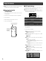
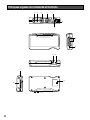
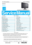
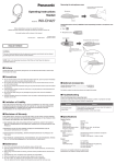
Major Operating Controls and Their Functions
y
t
r
e
w
i
u
+ VOL –
o
!0
!1 !2
EJECT
q
!3
!4
+
7
q Battery Lock [EJECT]
When removing the battery, slide out the lock.
When loading a battery, insert the battery until the lock
clicks.
Please note the direction that inserts the battery.
w Talk 1 Button [T1]
This button controls communications with the customer.
When the button is released, you can hear any customer
who is at the menu-board.
While the button is held down in the Press-To-Talk
mode, you can speak to the customer.
When the button is pressed in the Talk-Lock mode, you
can speak to the customer until you press the button a
second time.
e Talk 2 / A/B Lane Selection Button [T2, A/B]
This button can be set to two functions by the DIP switch
setting. Refer to P.14 "DIP Switch Setup".
[T2]
This button controls communications with the customer
on Lane B of double-drive-thrus.
When the button is released, you can hear any customer
who is at the menu board.
While the button is held down in the Press-To-Talk
mode, you can speak to the customer who is at the
menu board.
When the button is pressed in the Talk-Lock mode, you
can speak to the customer until you press the button a
second time.
[A/B]
This button switches from Lane A to B and vice versa.
The lane indicator i displays the selected lane in yellow
(A) or green (B).
r Page Button [P]
This button controls communications with store personnel.
When the button is released, you can hear the communications among store personnel.
While the button is held down in the Press-To-Page
mode, you can speak to store personnel.
When the button is pressed in the Page-Lock mode, you
can speak to the store personnel until you press the button a second time.
t Optional Function Button [R]
This button is intended for functional extension.
When the Order Taker is set in the manager mode and
this button is pressed, operation cannot be forwarded
for talking or paging. At that time, the Telephone
Indicator of the Center Module lights.
To recover the talk or page operation, press this button
again.
The Telephone Indicator is turned OFF and the talk and
page operation becomes possible.
8
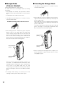
y External Device Control Button [C]
Press and hold the C button to turn on the external
device.
u Power Indicator
The indicator shows the status as follows.
Green: Power is supplied, and the unit is operating.
Green blinking: Power is supplied and Manager mode
is activated.
Red: The battery requires recharging.
Red blinking: ID is not registered, or the center module
is set to the ID Registration mode.
i Lane Indicator
Lights yellow or green to indicate which the lane is in
operation.
Yellow: Lane A is selected.
Green: Lane B is selected.
Yellow blinking: Lane A is being selected, and either
the Talk or Page mode is activated.
Green blinking: Lane B is being selected, and either
the Talk or Page mode is activated.
+ VOL –
o Volume Control Buttons [
]
Pressing the respective buttons will increase or
decrease the sound level.
!0 Power Button [POWER]
Pressing the button will turn the Order Taker on.
Pressing the button again for 2 seconds or more will turn
the Order Taker off.
!1 Earphone Output Jack
This jack is used for connection with the Panasonic WXH3027 Headset.
!2 Microphone Input Jack
This jack is used for connection with the Panasonic WXH3027 Headset.
!3 Switch Compartment
Do not open the cover of this compartment. It should be
opened only by qualified service personnel or system
installers.
!4 Battery (Optional accessory)
Refer to p. 6 "Precautions".
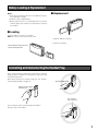
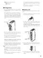
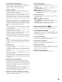
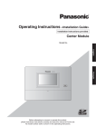
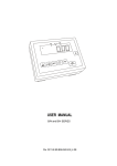
Battery Loading & Replacement
Notes:
• Refer to the operating instructions included with the battery and battery charger.
• Prepare a fully charged battery.
• Battery replacement is recommended when the power
indicator lights up in red and a constant beep is heard in
the headset.
■ Replacement
w
■ Loading
q
Insert the battery as shown in the figure.
Note: Be sure to insert it until the lock clicks.
1. Slide the battery lock down.
2. Remove the battery.
When inserting the battery, check the
positive and negative sides.
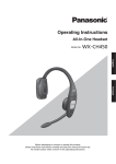
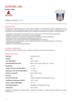
Connecting and Disconnecting the Headset Plug
When connecting the headset plug to this product, hold the
plug and push it straight into the earphone output jack and
microphone input jack.
When disconnecting the headset plug from this product,
hold the plug and pull it straight out.
Do not hold the cable.
Pull/insert the plug straight,
holding this part.
Do not pull this
part up and down.
Do not hold the cable or pull the plug up and down.
Doing so may cause trouble.
9
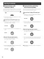
Operating Procedures
■ Communications with
Customers (TALK)
■ Communications with Other
Store Personnel (PAGE)
Any store personnel wearing the headset can communicate
bidirectionally with any customer who is at the menu board.
Store personnel wearing the headset can communicate with
each other without being heard by customers.
1. Select a proper sound level by pressing the button
or
.
+ VOL –
<When the Press-To-Page (PTP) mode is preset>
1. Hold down the P button and speak into the microphone
of the headset at a normal level.
2. You will hear a beep in the headset when a vehicle
arrives at the menu board.
Hold down
<When the Press-To-Talk (PTT) mode is preset>
1. Hold down the T1 button and speak to the customer.
A short beep is heard in the headset.
Hold down
2. Release the button. Your voice is not heard by the customer.
2. Release the button. Your voice will not be heard by the
other store personnel.
Release
<When the Page-Lock mode is preset>
1. Press the P button and speak into the microphone of
the headset at a normal level.
Release
Press
<When the Talk-Lock mode is preset>
1. Press the T1 button and speak to the customer.
A short beep is heard in the headset.
Press
2. Press the button again. The lock is released, and your
voice is not heard by the customer.
Press again
10
2. Press the P button again. The lock will be released, and
your voice will not be heard by the other store personnel.
Press again
Note: A maximum of 4 operators can have a conversation at
the same time.
■ Control of the device control terminals
The device control terminals of the center module can be
controlled through the Order Taker.
1. Hold down the C button. A short beep is heard from the
speaker of the headset and a connection will be made
toward the device control terminals of the center module.
Hold down
2. Release the C button. A short beep is heard twice from
the speaker of the headset and the connection will be
disconnected toward the device control terminals of the
center module.
Release
■ Double-Drive-Thru connections
When Double-Drive-Thru connections are made with the
center module, any Order Taker is required to select the
center module of either Lane A or Lane B.
<For Normal setup>
1. When a connection is made to Lane A, the lane indicator
is lit in yellow. Press the T2 button if you want to make a
connection changeover to Lane B. When connected to
Lane B, a voice of [Lane B] is heard from the speaker of
the headset and the lane indicator is lit in green.
Press
2. While a connection is maintained to Lane B, the lane
indicator is lit in green. Press the T2 button if you want to
make a connection changeover to Lane A. When connected to Lane A, a voice of [Lane A] is heard from the
speaker of the headset and the lane indicator is lit in yellow.
Press
<For Direct Lane Select setup>
1. While a connection is maintained to Lane A, the lane
indicator is lit in yellow. Press the T2 button if you want
to make a connection changeover to Lane B. When connected to Lane B, a voice of [Lane B] is heard from the
speaker of the headset and the lane indicator is lit in
green.
Press
2. While a connection is maintained to Lane B, the lane
indicator is lit in green. Press the T1 button if you want to
make a connection changeover to Lane A. When connected to Lane A, a voice of [Lane A] is heard from the
speaker of the headset and the lane indicator is lit in yellow.
Press
Note: When Direct Lane Select is set, TALK is available by
selecting either lane pressing T1 or T2 button.
11
■ Manager Mode
(Only one Headset)
Complete ID Registration to do this setting.
The Order Taker set to the Manager mode has following
functionality.
• The manager can interrupt store personnel's TALK or
PAGE at any time by monopolizing one channel by priority.
• The Manager hears audio from POS alone.
1. Hold down the power button for 2 seconds or more to
turn off the Order Taker.
Hold down the power button for two seconds or more to turn off.
2. While holding R and T1 simultaneously, press the power
button to turn on the Order Taker. The Order Taker
enters manager setting mode where the indicators and
buttons have different functions than in normal operation. You can hear "Connecting center module A" and
power indicator is an alternate blinking of red and green.
Also the Lane indicator A is blinking yellow.
Keep holding down.
(Lane A)
■ Canceling the Manager Mode
1. Hold down the power button for 2 seconds or more to
turn off the Order Taker.
2. When LANE A is set in the manager mode, keep pressing the R and T1 buttons simultaneously and start up the
power of Order Taker.
When LANE B is set in the manager mode, keep pressing the R and T2 buttons simultaneously and start up the
power of Order Taker.
The power indicator then blinks reciprocally in red and
green. A message of “Connecting Center Module A (or
B)” is heard from the Order Taker speaker.
Keep holding down.
(Lane A)
Keep holding down.
(Lane B)
3. When canceling of the manager mode is complete, reciprocal blinking of the power indicator turns to continuous lighting in green.
Keep holding down.
(Lane B)
When you want to register the manager in another center module in a double-drive-thru environment, while
holding R and T2 simultaneously, press the power button to turn on the Order Taker. You can hear
"Connecting center module B" and the power indicator
blinks red and green. Also the Lane indicator B blinks
green.
3. If manager mode setting is successful, you can hear
"Manager" and the power indicator blinks green.
12
■ Auto-Talk-Lock setup (for only
one Headset)
For a Order Taker where Auto-Talk-Lock is set up, it has a
function to select [Talk] automatically when the vehicle
detector has become active, and you can talk with the customer at the menu board.
1. Confirm that the dip switch 1 of the headset is ON, the
dip switch 2 is set at the objective lane, and the power
of the headset is OFF.
2. Turn on the Order Taker. The message "Hello Headset
**" (** is the number of headset) is output from the
speaker of the headset, and the power indicator blinks
green and red alternately for 3 seconds. While the indicator is blinking, press the T1 or T2 button. (LANE A: T1
button, LANE B: T2 button) Auto-Talk-Lock will be set
up, The message "Auto-Talk-Lock ON" is heard from the
speaker of the headset. When the T1 or T2 button is not
pressed, the Order Taker assumes an ordinary operation mode.
3. In the case of a failure in Auto-Talk-Lock setup, a voice
of [Failed] is heard from the speaker of the headset. In
this case, the same procedures should be followed from
Step 1 again.
Note: If the power of the Order Taker is turned OFF, all the
setting conditions for Auto-Talk-Lock will be canceled.
This setting should be carried out without fail when the
power supply is started up.
13
Setup Procedures
Caution: Setup of this product should only be performed by
qualified service personnel or system installers.
■ DIP Switch Setup
■ Opening the Switch
Compartment
An eight-bit DIP switch is provided for system setups. The
initial settings are marked with an asterisk *.
Note: Be sure to turn off the Order Taker in Step 1.
Otherwise, the DIP Switch will not be activated until you
turn the power off and on again.
1. Press the power button for 2 seconds or more to turn off
the Order Taker.
ON
OFF
3. Set the switches.
1
2
3
4
5
6
7
8
2. Unscrew the screw and open the switch compartment.
SW#
1
Initial Setting
4. After finishing the setup, replace the cover.
2
3
Function
Auto Talk Lock ON/OFF
Auto Talk Lock LANE
T2 Button Setting
5. Turn on the Order Taker.
4
5
Talk-Lock/Press-To-Talk
Page-Lock/Press-To-Page
6
Voice Prompt Language Select
7
8
Voice Prompt Language Select
RF Power
Reduce Power
Press the power button to
turn off the Order Taker.
ON
ON
B
Direct Lane Select
OFF
OFF*
A*
Normal*
Talk-Lock
Page-Lock
PTT*
PTP*
Full Power*
1. Press the power button for 2 seconds or more to turn off
the Order Taker.
Unscrew the
screw and open
the switch
compartment.
2. Set the switches as follows.
SW#1: This switch selects Auto Talk Lock ON/OFF
ON: Auto Talk Lock ON
OFF: Auto Talk Lock OFF
SW#2: This switch selects the target lane for "SW#1:
Auto Talk Lock".
ON: Lane B
OFF: Lane A
SW#3: This switch selects Direct Lane Select Mode or
Normal.
ON: Direct Lane Select Mode
When double-drive-thru, the T1 button is for lane
A, the T2 button is for lane B.
OFF: Normal
For double-drive-thru, the T2 button is A/B Lane
Selection.
SW#4: This switch selects Talk-Lock or Press-To-Talk
ON: Talk-Lock
OFF: PTT (Press-To-Talk)
SW#5: This switch selects Page-Lock or Press-To-Page.
ON: Page-Lock
OFF: PTP (Press-To-Page)
SW#6, SW#7: This switch selects language of Voice
Prompt.
SW#6
OFF*
OFF
ON
ON
14
SW#7
OFF*
ON
OFF
ON
Language
English
Spanish
French
Voice Prompt OFF
SW#8: This switch selects RF Power.
ON: Reduce Power
OFF: Full power
If you register IDs exceeding 32, the unused ID that has
been registered is automatically deleted in chronological
order.
• If ID registration is performed for 2 or more headsets,
follow the steps 2-4 individually.
■ ID Registration
1. Press the ID Registration button of the center module for
2 seconds or more. The system is changed to the ID
Registration mode.
2. While holding down the T1 and T2 buttons simultaneously, hold down the power button to turn on the Order
Taker. The Order Taker enters the ID Registration setting
mode where the indicators and buttons have different
functions than in normal operation. You will hear "ID
Registration Mode" and the power indicator will blink yellow.
■ Deletion of ID
To delete the registered ID of Order Taker follow the steps
below.
1. Hold down the POWER button for more than 2 seconds
to turn off the power of Order Taker.
Power on.
Keep holding down.
3. Press the T1 button, the Order Taker searches for the
center module. You can hear "Connecting center module A" and the lane Indicator will blink yellow.
2. To delete an ID that is registered for LANE A, keep
pressing the T1 and C buttons simultaneously and start
up the power of Order Taker.
To delete an ID that is registered for LANE B, keep
pressing the T2 and C buttons simultaneously and start
up the power of Order Taker. The power indicator then
blinks in yellow.
Keep holding down.
(Lane A)
* Press the T2 button (at double-drive-thru), for other center modules. You can hear "Connecting center module
B" and the lane indicator will blink green.
When the ID Registration succeeds, you will hear
"Registration Complete" and the headset number, and
the power indicator stops blinking and stays on.
4. When IDs are registered on all Order Takers, press the
ID Registration button of the center module, ID registration mode is completed. The power indicator of the
Order Taker will change from yellow to green.
Notes:
• If ID registration fails, a warning sounds "beep" and then
you will hear a voice prompt say "Failed". If registration
fails, the ID is not registered and the "Power" indicator
blinks red.
If this happens, turn off the power and try registering
again.
• All-in-One Headset or Order Taker that can register in
one center module is up to 32.
Keep holding down.
(Lane B)
3. Press the P button while the power indicator keeps blinking in yellow. The ID that is registered for LANE A (or
LANE B) is deleted.
4. The power indicator turns to blinking in red. A message of
“ID is not registered” is heard from the Order Taker
speaker.
15
Troubleshooting
Symptom
The power indicator blinks
red.
The headset ID is not registered in the center module of the target.
→ Register ID in the center module of the target.
The power indicator lights red
and a constant beep is heard
in the headphone.
The battery is almost exhausted.
→ Recharge the battery.
(Refer to the operating instructions of the battery charger.)
Cannot turn on the Order
Taker.
Cannot communicate with
other store personnel or the
customer at the menu board.
Cannot hear or talk to the
customer, but
communications with the store
personnel are OK.
Cannot "page" or "talk" in
certain areas.
Talk or page operation is
impossible from the Order
Taker set in the manager
mode.
16
Cause/solution
The battery is exhausted. The battery is not inserted correctly.
→ Recharge the battery. Position the battery properly.
Reference
pages
15
–
9
The center module may be turned off.
→ Turn on the power switch of the center module. (Refer to the
operating instructions of the center module.) If no remedy
exists, consult your dealer for repairs.
–
The headset ID is not registered in the center module of the target.
→ Register ID in the center module of the target.
15
The vehicle detector may be malfunctioning because the detector
is not plugged into the center module, no power is supplied, or
the detecting function is out of order.
→ Check that the vehicle detector is plugged in and has power.
(Refer to the operating instructions of the center module.)
If no remedy exists, consult your dealer for repairs.
Radio waves cannot reach the area.
→ Remove any metal obstacles blocking radio waves.
Check that the Telephone Indicator of the Center Module is not
turned ON.
If the indicator is turned ON, the Optional Function Button [R] is
turned ON.
→ Press the Optional Function Button [R] again and check that
the Telephone Indicator is turned OFF.
–
–
8
Specifications
Operating Frequency:
Required Power Supply:
Control Function:
Dimensions:
Weight (excluding battery):
Ambient operating temperature:
1 920 - 1 930 MHz
Rechargeable Li-ion Battery, 3.7 V DC
Power (On/Off)
Volume (Up/Down)
Talk (T1/T2)
Page
Lane Selection (A/B)
External Device Control (C)
DIP Switch Setup (8 bit)
121 mm (W) x 61 mm (H) x 24 mm (D)
{4-3/4" (W) x 2-13/32" (H) x 15/16" (D)}
115 g {0.25 lbs}
–10 °C to +50 °C {14 °F to 122 °F}
Dimensions and weighs indicated are approximate.
Specifications are subject to change without notice.
17
Standard Accessory
Operating Instructions (this manual) ................................ 1 pc.
Optional Accessories
Battery (Li-ion 3.7 V DC, 1 10 0 mAh) ............................... WX-B3030
Battery Charger ................................................................ WX-Z3040
Headset ............................................................................ WX-H3027
18
VERSION FRANÇAISE
(FRENCH VERSION)
AVERTISSEMENT:
FRANÇAIS
• Cet appareil doit être mis à la terre.
• Le périphérique doit être connecté à une prise de sortie secteur
munie d'une connexion de mise à la terre de sécurité.
• La prise de sortie secteur ou l'adaptateur d'alimentation du
périphérique doit toujours être prêt à être utiliser.
• Ne jamais exposer cet appareil à la pluie ni le laisser dans un lieu
humide sous peine de créer un amorçage électrique ou une
électrocution.
• L'appareil ne devrait pas être exposé à des éclaboussures ou
des projections d'eau et aucun récipient rempli de liquide tels que
des vases ne devraient être posé sur l'appareil.
• Tous les travaux d'installation de ce produit devraient être confiés
à des techniciens et dépanneurs professionnels ou des
installateurs de système.
• Pour éviter tout accident corporel, cet appareil doit être
solidement fixé au sol/au mur conformément aux directives
d'installation.
• Les connexions doivent être conformes au code électrique local.
• Le risque d'affaiblissement du système auditif dû à une
exposition à des niveaux sonores excessifs peut être limité par
une écoute à des volumes inférieurs et de plus courtes durées.
NMB-003
Cet appareil numérique de la classe A est conforme à la norme
NMB-003 du Canada.
RSS-213
L'utilisation de ce dispositif est autorisée seulement aux deux
conditions suivantes : (1) il ne doit pas produire de brouillage, et
(2) l'utilisateur du dispositif doit être prêt à accepter tout brouillage radioélectrique reçu, même si ce brouillage est susceptible
de compromettre le fonctionnement du dispositif.
ATTENTION:
• Risque d'explosion si la batterie n'est pas placée correctement.
Remplacer uniquement avec le même type ou un type
équivalent.
• Ces instructions de dépannage sont uniquement destinées au
personnel technique professionnel. Afin de limiter tout risque
d'électrocution, ne jamais exécuter de dépannage autre que
celui spécifié dans la notice d'instructions à moins que vous
possédiez des qualifications pour le faire.
Le numéro de modèle et le numéro de série de ce produit se
trouvent sur la surface de l'appareil.
Nous vous conseillons de relever le numéro de série de votre
appareil dans l'espace réservé ci-dessous et de conserver
précieusement votre notice d'instructions en tant que
justificatif d'achat aux fins d'identification en cas de vol.
No. de modèle
No. de série
19
Limitation de responsabilité
CETTE PUBLICATION EST FOURNIE "COMME TEL" SANS GARANTIE DE TOUTE SORTE, EXPRÈS OU IMPLICITE, ÉTANT
INCLUSE MAIS NON LIMITÉE AUX GARANTIES IMPLICITES DE LA VALEUR MARCHANDE, ADAPTATION POUR TOUT BUT
PARTICULIER OU NON-INFRACTION DES DROITS D'UN TIERS.
Déni de la garantie
EN AUCUN CAS MATSUSHITA ELECTRIC INDUSTRIAL
CO., LTD. NE SERA TENU POUR RESPONSABLE POUR
TOUTE PARTIE OU TOUTE PERSONNE, À L'EXCEPTION
DU
REMPLACEMENT
OU
D'UNE
MAINTENANCE
RAISONNABLE DE CE PRODUIT POUR LES CAS CITÉS,
INCLUS MAIS NON LIMITÉS À CE QUI SUIT:
(1) TOUT DÉGÂT ET PERTE, Y COMPRIS SANS
LIMITATION, DIRECT OU INDIRECT, SPÉCIAL,
IMPORTANT OU EXEMPLAIRE, SURVENANT OU
CONCERNANT LE PRODUIT;
(2) BLESSURE PERSONNELLE OU TOUT DÉGÂT CAUSÉS
PAR UN USAGE NON APPROPRIÉ OU UNE
UTILISATION NÉGLIGENTE DE L'UTILISATEUR;
(3) DÉMONTAGE, RÉPARATION OU MODIFICATION NON
AUTORISÉS
DU
PRODUIT
EFFECTUÉS
PAR
L'UTILISATEUR;
20
(4) TOUT PROBLÈME, INCOMMODITÉ IMPORTANTE OU
PERTE OU ENDOMMAGEMENT, SURVENANT DU
SYSTÈME COMBINÉ PAR LES APPAREILS DE TIERS.
Instructions de sécurité importantes
1) Veiller à lire ces instructions.
2) Conserver ces instructions.
3) Tenir compte de tous les avertissements.
4) Se conformer à toutes les instructions.
5) Ne pas utiliser cet appareil près de lieux en présence d'eau.
6) Nettoyer uniquement avec un chiffon sec.
7) N'obturer aucune des ouvertures d'aération. Installer conformément aux instructions du fabricant.
8) Ne pas utiliser à proximité de sources de chaleur telles que des radiateurs, des bouches de chauffage, des appareils de
chauffage ou tout autre appareil (y compris les amplificateurs) produisant de la chaleur.
9) Ne pas asservir l'objectif de sécurité de la prise polarisée ou de la prise de mise à la terre. Une prise polarisée possède
deux lames dont l'une est plus large que l'autre. Une prise de mise à la terre possède deux lames ainsi qu'un troisième
élément, un ergot de mise à la terre. La lame qui est large ou le troisième élément, l'ergot, sont installés pour assurer votre
sécurité. Si la prise fournie ne s'engage pas correctement dans votre prise, veuillez consulter un électricien pour qu'il
effectue le remplacement de l'ancienne prise de sortie secteur.
10) Protéger le cordon d'alimentation afin que personne ne puisse marcher dessus ni ne soit pincé, notamment près des prises,
les prises pratiques et les points de sortie de l'appareil.
11) Utiliser uniquement les fixations ou les accessoires spécifiés par le fabricant.
12) Utiliser uniquement le chariot, le support, le trépied, la platine de fixation ou la tablette spécifiée par le fabricant ou vendu
avec l'appareil. Quand un chariot est utilisé, prendre toutes les précautions nécessaires lors du déplacement de la
combinaison chariot-appareil afin que le tout ne se renverse pas.
S3125A
13) Débrancher cet appareil pendant les orages électriques ou s'il n'est pas utilisé sur de longues périodes de temps.
14) Toute réparation ou dépannage doit être confié à un personnel qualifié. Un dépannage est nécessaire lorsque l'appareil a
été endommagé d'une manière quelconque, par exemple, lorsque le cordon d'alimentation électrique ou la prise ont été
endommagés, quand du liquide s'est répandu dessus ou si des objets sont tombés dans l'appareil, lorsque l'appareil a été
exposé à la pluie ou à l'humidité, ne fonctionne pas normalement ou s'il a fait une chute.
21
TABLE DES MATIÈRES
Limitation de responsabilité ........................................................................................................................20
Déni de la garantie ......................................................................................................................................20
Instructions de sécurité importantes ...........................................................................................................21
Préface ........................................................................................................................................................23
Caractéristiques dominantes ......................................................................................................................23
Mesures de précaution ...............................................................................................................................23
Principaux organes de commande et fonctions ..........................................................................................24
Chargement et remplacement de la batterie ..............................................................................................26
■ Chargement ...........................................................................................................................................26
■ Remplacement ......................................................................................................................................26
Branchement et débranchement de la fiche de combiné microcasque d'écoute .....................................26
Modes d'utilisation .......................................................................................................................................27
■ Communications avec les clients (TALK) ..............................................................................................27
■ Communication avec d'autres membres du personnel du magasin (PAGE) .......................................27
■ Bornes de commande de périphérique extérieur .................................................................................28
■ Connexion de système double de service clientèle de passage (Double-Drive-Thru) ........................28
■ Mode de gérant (seulement un combiné microcasque d'écoute) ........................................................29
■ Annulation du mode gérant ...................................................................................................................29
■ Configuration de la fonction de verrouillage automatique pour parler
(pour seulement un combiné microcasque d'écoute) (Auto-Talk-Lock) ...............................................30
Procédures de configuration .......................................................................................................................31
■ Ouverture du logement de commutateur ..............................................................................................31
■ Configuration d'interrupteur DIP ............................................................................................................31
■ Enregistrement d'identification ..............................................................................................................32
■ Suppression d'une identification ...........................................................................................................32
Dépannage...................................................................................................................................................33
Caractéristiques techniques .......................................................................................................................34
Accessoire standard ...................................................................................................................................35
Accessoires optionnels ...............................................................................................................................35
22
Préface
Le preneur de commande WX-T3020 est exclusivement conçu pour être utilisé avec les systèmes de communication à liaison
radio Panasonic dont on se sert dans les tableaux de menu de service clientèle de passage, etc. En utilisant le combiné
microcasque d'écoute WX-H3027 optionnel, les utilisateurs peuvent communiquer avec d'autres éléments du personnel du
magasin et les clients.
Caractéristiques dominantes
• Ce preneur de commande peut être utilisé avec le module central WX-C3010.
• 1,9 GHz DECT* est employé avec le preneur de commande afin d'empêcher toute interférence par les fours à micro-ondes
ou le réseau local sans fil utilisés avec 2,4 GHz DECT.
*Télécommunications sans fil améliorées par numérique
• Mode administrateur
Il est possible de régler le mode de gérant sur un des preneurs de commande enregistrés dans le module central. Une
personne se servant du preneur de commande a la priorité de communication.
• Il est possible de sélectionner le passage direct ou le passage A/B selon les dispositions de système double de service
clientèle de passage.
• Il est possible de sélectionner le mode de verrouillage pour parler ou mode presser pour parler.
• Il est possible de sélectionner le mode de verrouillage page ou le mode presser pour page.
Mesures de précaution
•
•
•
•
Utiliser seulement la batterie WX-B3030.
Se conformer aux instructions de précaution et d'utilisation de la batterie.
En combinaison avec ce produit, se référer aux Manuel d'utilisation du chargeur de batterie WX-Z3040.
Pour prévenir tout dégât, débranchez le combiné microcasque d'écoute WX-H3027 du preneur de commande WX-T3020
lorsque les appareils sont rangés.
• Utiliser le combiné microcasque d'écoute avec le rembourrage d'écouteur fixé. Autrement, la voix risque d'être déformée ou
l'on peut éprouver des difficultés à entendre la voix.
• Arrêter le preneur de commande quand celui-ci n'est pas utilisé de manière à économiser la vie de la batterie.
• Ne pas utiliser ce produit si vous utilisez un équipement médical électrique implanté. Ceci peut provoquer un
dysfonctionnement de l'équipement.
23
Principaux organes de commande et fonctions
y
t
r
e
w
i
u
+ VOL –
o
!0
!1 !2
EJECT
q
!3
!4
24
+
q Verrouillage de la batterie [EJECT]
Faire coulisser le verrouillage pour retirer la batterie.
Lors du chargement d'une batterie, introduire la batterie
jusqu'à ce qu'elle se verrouille en place.
Veuiller noter le sens pour insérer la batterie.
w Bouton 1 Parler [T1]
Ce bouton contrôle les communications avec le client.
Lorsque le bouton est relâché, tout ce que dit le client
au tableau de menu est entendu.
Alors que le bouton est maintenu pressé en mode
presser pour parler, il est possible de parler au client.
Alors que le bouton est maintenu pressé en mode de
verrouillage pour parler, il est possible de parler au
client jusqu'à ce que le bouton soit pressé une seconde
fois.
e Bouton de sélection Parler 2 / Passage A/B [T2, A/B]
Ce bouton peut être réglé sur deux fonctions suivant le
réglage de l'interrupteur à positions multiples. Se référer
à p. 31 à "Configuration d'interrupteur DIP".
[T2]
Ce bouton contrôle les communications avec le client
sur le passage B d'un système double de service
clientèle de passage.
Lorsque le bouton est relâché, tout ce que dit le client
au tableau de menu est entendu.
Alors que le bouton est maintenu pressé en mode
presser pour parler, il est possible de parler au client se
trouvant à la hauteur du tableau de menu.
Alors que le bouton est maintenu pressé en mode de
verrouillage pour parler, il est possible de parler au
client jusqu'à ce que le bouton soit pressé une seconde
fois.
[A/B]
Ce bouton commute entre le passage A et le passage B
et vice versa. L'indicateur de passage i affiche le
passage actuellement sélectionné en jaune (A) ou en
vert (B).
r Bouton Page [P]
Ce bouton contrôle les communications avec le
personnel du magasin.
Lorsque le bouton est relâché, les communications entre
les membres du personnel du magasin peuvent être
entendues.
Alors que le bouton est maintenu pressé en mode
presser pour page, il est possible de parler au
personnel du magasin.
Alors que le bouton est maintenu pressé en mode de
verrouillage page, il est possible de parler au personnel
du magasin jusqu'à ce que le bouton soit pressé une
seconde fois.
u Indicateur d'alimentation
L'indicateur montre l'état actuel comme suit.
Vert: L'alimentation est appliquée et l'appareil est en
fonction.
Clignote en vert: L'alimentation est appliquée et le
mode de gérant est activé.
Rouge: La batterie doit être rechargée.
Rouge clignotant: L'identification n'est pas enregistrée
ou le module central est réglé en mode d'enregistrement d'identification.
i Indicateur de passage
Il s'allume en jaune ou en vert pour indiquer quel est le
passage en service.
Jaune: Le passage A est sélectionné
Vert: Le passage B est sélectionné.
Jaune clignotant: Le passage A est sélectionné et soit
le mode parler soit le mode page est activé.
Clignote en vert: Le passage B est sélectionné et soit
le mode parler soit le mode page est activé.
+ VOL –
o Boutons de réglage de volume [
]
Une pression des boutons respectifs a pour effet
d'augmenter ou de diminuer le niveau de sortie son.
!0 Bouton d'alimentation [POWER]
Le fait d'appuyer sur le bouton met le preneur de
commande en marche. Une nouvelle pression du
bouton pendant au moins 2 secondes permet d'arrêter
le preneur de commande.
!1 Prise de sortie d'écouteur
Cette prise est utilisée pour le raccordement au
combiné microcasque d'écoute WX-H3027.
!2 Prise d'entrée de microphone
Cette prise est utilisée pour le raccordement au
combiné microcasque d'écoute WX-H3027.
!3 Logement d'interrupteur
Ne pas ouvrir le couvercle de ce logement. Ne doit être
ouvert que par un technicien professionnel ou des
installateurs de système qualifiés.
!4 Batterie (accessoire optionnel)
Se référer à la page 23 à "Mesures de précaution".
t Bouton de fonction optionnelle [R]
Ce bouton est réservé à une extension fonctionnelle.
Quand le preneur de commande est réglé en mode de
gérant et que ce bouton est pressé, l'opération ne peut
pas être suivie pour parler ou faire une recherche de
personne. À ce moment-là, l'indicateur de téléphone du
module central s'allume.
Pour rétablir l'opération parler ou de recherche de
personne, appuyer encore une fois sur le bouton.
L'indicateur de téléphone est éteint et l'opération parler
et recherche de personne devient possible.
y Bouton de commande de périphérique externe [C]
Appuyer et maintenir le bouton C enfoncé pour mettre
en marche le périphérique externe.
25
Chargement et remplacement de la batterie
Remarques:
• Se référer aux manuels d'utilisation qui accompagnent
la batterie et le chargeur de batterie.
• Se munir d'une batterie complètement chargée.
• Le remplacement de la batterie est recommandé quand
le témoin d'alimentation s'allume en rouge et qu'un bip
continu est entendu régulièrement dans le combiné
microcasque.
■ Remplacement
w
■ Chargement
Introduire la batterie comme représenté sur la figure.
Remarque: Faire en sorte de l'introduire jusqu'à son
verrouillage.
q
1. Faire coulisser le verrouillage de la batterie vers le bas.
2. Retirer la batterie.
Vérifier les pôles positif et négatif au
moment de l'introduction de la batterie.
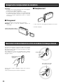
Branchement et débranchement de la fiche de combiné microcasque d'écoute
Au moment de brancher la fiche du combiné microcasque
d'écoute à ce produit, maintenir la fiche et la pousser
directement dans la prise de sortie d'écouteur et la prise
d'entrée de microphone.
Pour débrancher la fiche de raccordement du combiné
microcasque d'écoute de cet appareil, saisir la prise et la
dégager tout droit.
Ne pas saisir le câble.
Dégager la fiche tout droit
tout en saisissant
cette partie.
Ne pas dégager cette partie
vers le haut ou vers le bas.
Ne pas saisir le câble ni dégager la prise vers le haut ou
vers le bas.
Cette façon de faire peut constituer un problème.
26
Modes d'utilisation
■ Communications avec les
clients (TALK)
Tout membre du personnel portant un combiné
microcasque peut communiquer en mode bidirectionnel
avec n'importe quel client qui se trouve à la hauteur du
tableau de menu.
■ Communication avec d'autres
membres du personnel du
magasin (PAGE)
Tous les membres du personnel portant un combiné
microcasque peuvent communiquer entre eux sans être des
clients.
1. Sélectionner un niveau sonore approprié en appuyant
sur le bouton
ou
.
+ VOL –
<Lorsque le mode presser pour page (PTP) est
préréglé>
1. Presser et immobiliser le bouton P et parler dans le
microphone avec un réglage de niveau normal.
2. Une tonalité est entendue dans le combiné microcasque
quand un véhicule arrive à la hauteur du tableau de
menu.
<Lorsque le mode presser pour parler (PTT) est
préréglé>
1. Presser et immobiliser le bouton T1 et parler au client.
Un bip très court se manifeste dans le combiné
microcasque.
Presser et
immobiliser
2. Relâcher le bouton. Votre voix ne sera pas perceptible
par les autres personnes du personnel du magasin.
Libérer
Presser et
immobiliser
2. Relâcher le bouton. Votre voix ne sera pas perceptible
par le client.
<Lorsque le mode de verrouillage page est
préréglé>
1. Presser et immobiliser le bouton P et parler dans le
microphone du combiné microcasque d'écoute avec un
réglage de niveau normal.
Libérer
Presser
<Lorsque le mode de verrouillage pour parler
est préréglé>
1. Presser le bouton T1 et parler au client.
Un bip très court se manifeste dans le combiné
microcasque.
2. Appuyer encore une fois sur le bouton P. Le verrouillage
sera libéré et votre voix ne sera plus perceptible par le
client.
Presser encore
une fois
Presser
2. Appuyer encore une fois sur le bouton. Le verrouillage
sera libéré et votre voix ne sera plus perceptible par le
client.
Remarque: Un nombre maximum de quatre opérateurs
peuvent tenir une conversation en même temps.
Presser encore
une fois
27
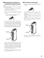
■ Bornes de commande de
périphérique extérieur
Les bornes de commande de périphérique du module
central peuvent être contrôlées par l'intermédiaire du
preneur de commande.
1. Immobiliser le bouton C en position basse. Un bip court
est entendu par le haut-parleur du combiné
microcasque d'écoute et une connexion sera établie à
destination des bornes de commande de périphérique
du module central.
<Pour une configuration de système double de
service clientèle de passage>
1. Quand une connexion est maintenue sur le passage A,
l'indicateur de passage s'allume en jaune. Appuyer sur
le bouton T2 si l'on souhaite faire un changement de
connexion vers le passage B. Une fois connecté au
passage B, une voix [Lane B] est entendue par le hautparleur du combiné microcasque d'écoute et l'indicateur
de passage s'allume en vert.
Presser
Presser et
immobiliser
2. Relâcher le bouton C. Un bip court est entendu deux
fois par le haut-parleur du combiné microcasque
d'écoute et la connexion sera coupée vers les bornes
de commande de périphérique du module central.
2. Quand une connexion est maintenue sur le passage B,
l'indicateur de passage s'allume en vert. Appuyer sur le
bouton T1 si l'on souhaite faire un changement de
connexion vers le passage A. Une fois connecté au
passage A, une voix [Lane A] est entendue par le hautparleur du combiné microcasque d'écoute et l'indicateur
de passage s'allume en jaune.
Libérer
Presser
■ Connexion de système double
de service clientèle de passage
(Double-Drive-Thru)
Quand les connexions de système double de service
clientèle de passage sont établies avec le module central,
n'importe quel preneur de commande est obligé de
sélectionner le module central du passage A ou du passage
B.
<Pour une configuration normale>
1. Quand une connexion est établie au passage A,
l'indicateur de passage s'allume en jaune. Appuyer sur
le bouton T2 si l'on souhaite faire un changement de
connexion vers le passage B. Une fois connecté au
passage B, une voix [Lane B] est entendue par le hautparleur du combiné microcasque d'écoute et l'indicateur
de passage s'allume en vert.
Presser
2. Quand une connexion est maintenue sur le passage B,
l'indicateur de passage s'allume en vert. Appuyer sur le
bouton T2 si l'on souhaite faire un changement de
connexion vers le passage A. Une fois connecté au
passage A, une voix [Lane A] est entendue par le hautparleur du combiné microcasque d'écoute et l'indicateur
de passage s'allume en jaune.
Presser
28
Remarque: Quand Sélection de passage direct est réglée,
TALK est disponible en sélectionnant l'un ou l'autre
passage en appuyant sur le bouton T1 ou le bouton T2.
■ Mode de gérant (seulement un
combiné microcasque d'écoute)
Effectuer l'enregistrement d'identification, pour faire ce
réglage.
Le combiné microcasque d'écoute réglé en mode de gérant
a la fonctionnalité suivante.
• Le gérant peut interrompre le mode TALK ou PAGE de
tout membre du personnel à tout moment en
monopolisant un canal par priorité.
• Le gérant entend le son de POS seulement.
1. Appuyer et immobiliser le bouton d'alimentation pendant
au moins 2 secondes pour arrêter le preneur de
commande.
Appuyer et immobiliser le bouton d'alimentation pendant au
moins deux secondes pour arrêter l'appareil.
2. Tout en pressant et immobilisant simultanément les
boutons R et T1, presser le bouton d'alimentation pour
mettre le preneur de commande en marche. Le preneur
de commande passe en mode de gérant quand les
témoins et les boutons ont des fonctions différentes de
celles du fonctionnement normal. Il est possible
d'entendre "Connecting center module A" et le témoin
d'alimentation clignote alternativement du rouge au vert.
En outre, l'indicateur de passage A clignote en jaune.
Maintenir pressé.
(Passage A)
■ Annulation du mode gérant
1. Appuyer et immobiliser le bouton d'alimentation pendant
au moins 2 secondes pour arrêter le preneur de
commande.
2. Quand PASSAGE A est réglé en mode de gérant,
continuer à appuyer sur les boutons R et T1
simultanément et mettre en marche le preneur de
commande.
Quand PASSAGE B est réglé en mode de gérant,
continuer à appuyer sur les boutons R et T2
simultanément et mettre en marche le preneur de
commande.
Le témoin d'alimentation clignote alternativement en
rouge et en vert. Un message "Connecting Center
Module A (or B)" est entendu par le haut-parleur du
preneur de commande.
Maintenir pressé.
(Passage A)
Maintenir pressé.
(Passage B)
3. Quand le mode de gérant est annulé, un clignotement
réciproque du témoin d'alimentation commence pour
rester allumé en vert.
Maintenir pressé.
(Passage B)
Quand on souhaite enregistrer le gérant dans un autre
module central dans un environnement de système
double de service clientèle de passage, tout en
maintenant R et T2 enfoncés simultanément, appuyer
sur le bouton d'alimentation pour mettre en marche le
preneur de commande. Il est possible d'entendre
"Connecting center module B" et le témoin d'alimentation
clignote alternativement du rouge au vert. En outre,
l'indicateur de passage B clignote au vert.
3. Si le réglage de mode de gérant se déroule avec
succès, il est possible d'entendre "Manager" et le témoin
d'alimentation clignote en vert.
29
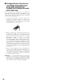
■ Configuration de la fonction de
verrouillage automatique pour
parler (pour seulement un
combiné microcasque d'écoute)
(Auto-Talk-Lock)
Pour un preneur de commande où la fonction de
verrouillage automatique pour parler est configurée, il a une
fonction pour sélectionner [Parler] automatiquement quand
le détecteur de véhicule est devenu actif, et si l'on parle
avec le client au tableau de menu.
1. Confirmer que l'interrupteur à positions multiples 1 du
combiné microcasque d'écoute est en fonction, que
l'interrupteur à positions multiples 2 est réglé sur le
passage objectif et que l'alimentation du combiné
microcasque d'écoute est coupée.
2. Mettre le preneur de commande sous tension. Le
message "Hello Headset **" (** correspond au numéro
du combiné microcasque d'écoute) est émis par le hautparleur du combiné microcasque d'écoute et le témoin
d'alimentation clignote en vert et en rouge
alternativement pendant 3 secondes. Tandis que le
témoin d'alimentation clignote, appuyer sur le bouton T1
ou T2. (PASSAGE A: Bouton T1, PASSAGE B: Bouton
T2) La fonction de verrouillage automatique pour parler
sera paramétrée, le message "Auto-Talk-Lock ON" est
entendu par le haut-parleur du combiné microcasque
d'écoute. Quand le bouton T1 ou T2 n'est pas pressé, le
preneur de commande assume un mode ordinaire de
fonctionnement.
3. Dans le cas d'une défaillance de la configuration de la
fonction de verrouillage automatique pour parler, une
voix [Failed] est entendue par le haut-parleur du
combiné microcasque d'écoute. Dans ce cas de figure,
se conformer à nouveau aux instructions des mêmes
procédures indiquées à l'étape 1.
Remarque: Si le courant d'alimentation du preneur de
commande est coupé, toutes les conditions de réglage
pour la fonction de verrouillage automatique pour parler
seront annulées. Ce réglage devrait être effectué sans
faute quand l'alimentation électrique est appliquée.
30
Procédures de configuration
Précautions: La configuration de ce produit doit être
exécutée par un personnel de dépannage qualifié ou
des installateurs professionnels.
ON
1
2
3
4
5
6
7
8
OFF
■ Ouverture du logement de
commutateur
SW# Fonction
1. Appuyer et immobiliser le bouton d'alimentation pendant
au moins 2 secondes pour arrêter le preneur de
commande.
2. Dévisser la vis et ouvrir le logement de commutateur.
3. Régler les commutateurs.
4. Après avoir
couvercle.
positionné
l'interrupteur,
remonter
le
5. Mettre le preneur de commande sous tension.
Appuyer sur le bouton d'alimentation pour
arrêter le preneur de commande.
Dévisser la vis
et ouvrir le
logement de
commutateur.
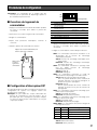
■ Configuration d'interrupteur DIP
Un interrupteur DIP à huit bits est installé pour effectuer les
configurations de système. Les réglages initiaux sont
identifiés par un astérisque *.
Remarque: Ne pas oublier de couper l'alimentation du
preneur de commande au cours de l'étape 1. En ne
procédant pas ainsi, l'interrupteur à positions multiples
ne sera pas activé tant que l'alimentation ne sera pas
coupée puis rétablie.
Paramétrage initial
ON
OFF
1
Verrouillage automatique pour
parler activée/désactivée
ON
OFF*
2
Passage de verrouillage
automatique pour parler
B
A*
3
Paramétrage de bouton T2
Sélection directe
de passage
Normal*
4
5
Verrouillage pour parler/Presser pour parler Verrouillage pour parler PTT*
6
Sélection de langue de message vocal
7
8
Sélection de langue de message vocal
Verrouillage page/Presser pour page
Alimentation RF
Verrouillage page
PTP*
Réduit l'alimentation
Pleine puissance*
1. Appuyer et immobiliser le bouton d'alimentation pendant
au moins 2 secondes pour arrêter le preneur de
commande.
2. Régler les commutateurs comme indiqué ci-dessous.
SW#1: Ce commutateur sélectionne l'activation ou la
désactivation de la fonction de verrouillage
automatique pour parler
Activé: Fonction de verrouillage automatique pour
parler activée
Désactivé: Fonction de verrouillage automatique
pour parler désactivée
SW#2: Ce commutateur sélectionne le passage ciblé
pour for "SW#1: Fonction de verrouillage
automatique pour parler".
Activé: Passage B
Désactivé: Passage A
SW#3: Ce commutateur sélectionne le mode de
sélection directe de passage ou le mode normal.
Activé: Mode de sélection directe de passage
Avec un système double de service clientèle de
passage, le bouton T1 est pour le passage A, le
bouton T2 est pour le passage B.
Désactivé: Normal
Pour le système double de service clientèle de
passage, le bouton T2 est pour la sélection de
passage A/B.
SW#4: Ce commutateur sélectionne verrouillage pour
parler ou presser pour parler
Activé: Verrouillage pour parler
Désactivé: PTT (Presser pour parler)
SW#5: Ce commutateur sélectionne verrouillage pour
page ou presser pour page
Activé: Verrouillage page
Désactivé: PTP (Presser pour page)
SW#6, SW#7: Ce commutateur sélectionne la langue de
messages de vocaux.
SW#6
OFF*
OFF
ON
ON
SW#7
OFF*
ON
OFF
ON
Langue
Anglais
Espagnol
Français
Désactivation de message vocal
SW#8: Ce commutateur sélectionne l'alimentation RF.
Activé: Réduit l'alimentation
Désactivé: Pleine puissance
31
■ Enregistrement d'identification
1. Appuyer sur le bouton d'enregistrement ID du module
central pendant au moins 2 secondes. Le système
passe en mode d'enregistrement d'identification.
2. Tout en pressant et immobilisant simultanément les
boutons T1 et T2, appuyer et maintenir le bouton
d'alimentation enfoncé pour mettre le preneur de
commande en marche. Le preneur de commande passe
en mode de paramétrage d'enregistrement d'identification quand les témoins et les boutons ont des
fonctions différentes de celles du fonctionnement
normal. On entend alors "ID Registration Mode" et le
témoin d'alimentation clignote en jaune.
• Si l'enregistrement d'identification est exécuté pour 2 ou
davantage de combinés microcasque d'écoute, se
conformer aux étapes 2-4 individuellement.
■ Suppression d'une identification
Pour supprimer une identification enregistrée d'un preneur
de commande, suivre les étapes indiquées ci-dessous.
1. Appuyer et immobiliser le bouton d'alimentation POWER
pendant au moins 2 secondes secondes pour arrêter le
preneur de commande.
Maintenir pressé.
Mise sous tension.
2. Pour supprimer une identification enregistrée pour
PASSAGE A, continuer à appuyer sur les boutons T1 et
C simultanément et mettre en marche le preneur de
commande.
Pour supprimer une identification enregistrée pour
PASSAGE B, continuer à appuyer sur les boutons T2 et
C simultanément et mettre en marche le preneur de
commande. Le témoin d'alimentation clignote en jaune.
3. Appuyer sur le bouton T1 pour que le preneur de
commande recherche le module central. On entend
alors "Connecting center module A" et l'indicateur de
passage clignote en jaune.
Maintenir pressé.
(Passage A)
* Appuyer sur le bouton T2 (pour le système double de
service clientèle de passage) pour la sélection d'autres
modules centraux. On entend alors "Connecting center
module B" et l'indicateur de passage clignote en vert.
Quand l'enregistrement d'identification a réussi avec
succès, on entend alors "Registration Complete" et le
numéro de combiné microcasque d'écoute et le témoin
d'alimentation cessent de clignoter et restent allumés.
4. Quand des identifications sont enregistrées sur tous les
preneurs de commande, appuyer sur le bouton
d'enregistrement d'identification du module central, le
mode d'enregistrement d'identification se termine. Le
témoin d'alimentation du preneur de commande
passera du jaune au vert.
Remarques:
• Si l'enregistrement d'identification échoue, des sons de
rappel "bip-bip" sont produits et l'on entend alors un
message de rappel qui dit "Failed". Si l'enregistrement
échoue, l'identification n'est pas enregistrée et le témoin
"Power" clignote en rouge.
Quand cela se produit, couper l'alimentation et refaire
une tentative d'enregistrement.
• Le combiné microcasque tout intégré ou le preneur de
commande qui peut être enregistré dans un module
central est jusqu'à 32.
Si l'on enregistre une identification dépassant un
nombre de 32, l'identification enregistrée inutilisée est
automatiquement effacée dans l'ordre chronologique.
32
Maintenir pressé.
(Passage B)
3. Appuyer sur le bouton P tandis que le témoin
d'alimentation continue à clignoter en jaune.
L'identification qui est enregistrée pour PASSAGE A (ou
PASSAGE B) est effacée.
4. Le témoin d'alimentation passe en clignotement rouge.
Un message "ID is not registered" est entendu par le
haut-parleur du preneur de commande.
Dépannage
Symptôme
Origine/Solution
Le témoin d'alimentation
clignote en rouge.
L'identification du combiné microcasque d'écoute n'est pas
enregistrée dans le module central ciblé.
→ L'identification du combiné microcasque d'écoute n'est
pas enregistrée dans le module central ciblé.
Le témoin d'alimentation
s'allume en rouge tandis
qu'un bip continu est entendu
dans le casque d'écoute.
La batterie est presque épuisée.
→ Recharger la batterie.
(Se reporter au manuel d'instructions du chargeur de
batterie.)
Impossibilité de mettre le
preneur de commande en
marche.
La batterie est épuisée. La batterie n'est pas introduite
correctement.
→ Recharger la batterie. Orienter correctement la batterie.
Impossibilité de communiquer
avec les autres membres du
personnel du magasin ou
avec le client qui se trouve à
la hauteur du tableau de
menu.
Le module central est peut être arrêté.
→ Mettre le module central sous tension avec l'interrupteur
d'alimentation. (Se reporter au manuel d'instructions du
module central.) S'il n'existe aucun moyen de rectifier,
consulter le distributeur pour qu'il effectue les réparations
nécessaires.
L'identification du combiné microcasque d'écoute n'est pas
enregistrée dans le module central ciblé.
→ L'identification n'est pas enregistrée dans le module
central ciblé.
Pages de
référence
32
–
26
–
32
Impossibilité d'entendre ni de
parler au client alors que la
communication avec les
autres membres du personnel
du magasin est normale.
Le détecteur de véhicule est peut être en dysfonctionnement
parce qu'il n'est pas branché dans le module central ou bien
parce que l'alimentation n'est pas fournie ou encore que la
fonction de détection est déréglée.
→ Vérifier que le détecteur de véhicule est branché et est
alimenté.
(Se reporter au manuel d'instructions du module central.)
S'il n'existe aucun moyen de rectifier, consulter le
distributeur pour qu'il effectue les réparations nécessaires.
–
Impossibilité de passer en
mode "page" ou en mode
"parler" dans certaines zones.
Les ondes radio ne peuvent pas atteindre la zone.
→ Retirer tout obstacle métallique risquant de bloquer les
ondes radio.
–
L'opération parler ou
recherche de personne à
partir du preneur de
commande en mode de
gérant est impossible.
Vérifier que l'indicateur de téléphone du module central n'est
pas allumé.
Si l'indicateur est allumé, le bouton de fonction optionnelle [R]
est activé.
→ Appuyer encore une fois sur le bouton de fonction
optionnelle [R] et vérifier que l'indicateur de téléphone est
éteint.
25
33
Caractéristiques techniques
Fréquence d'utilisation:
Alimentation requise:
Fonction de commande:
Dimensions:
Poids (à l'exclusion de la batterie):
Température ambiante en service:
1 920 - 1 930 MHz
Batterie rechargeable Li-ion, 3,7 V à courant continu
Alimentation (marche/arrêt)
Volume (accroissement/réduction)
Parler (T1/T2)
Page
Sélection de passage (A/B).
Commande de périphérique externe (C)
Configuration d'interrupteur à positions multiples (8 bits)
121 mm (L) x 61 mm (H) x 24 mm (P)
{4-3/4" (L) x 2-13/32" (H) x 15/16" (P)}
115 g {0,25 lbs}
–10 °C à +50 °C {14 °F à 122 °F}
Les poids et dimensions indiqués sont approximatifs.
Sous réserve de modification des renseignements techniques sans préavis.
34
Accessoire standard
Manuel d'utilisation (cette documentation) ............................................. 1 él.
Accessoires optionnels
Batterie (Li-ion 3,7 V c.c., 1 100 mAh) .................................................... WX-B3030
Chargeur de batterie .............................................................................. WX-Z3040
Combiné microcasque d'écoute ............................................................ WX-H3027
35
Panasonic System Solutions Company,
Unit Company of Panasonic Corporation of North America
www.panasonic.com/business/
For customer support, call 1.800.528.6747
Three Panasonic Way 2H-2, Secaucus, New Jersey 07094
Panasonic Sales Company
Division of Panasonic Puerto Rico Inc.
San Gabriel Industrial Park 65th Infantry Ave. KM. 9.5
Carolina
P.R. 00985(809)750-4300
Panasonic Canada Inc.
5770 Ambler Drive,Mississauga,
Ontario, L4W 2T3 Canada (905)624-5010
http://www.panasonic.ca
© 2008 Matsushita Electric Industrial Co., Ltd. All Rights Reserved.
NM0708-1088
3TR005572BAA
Printed in Japan
Imprimé au Japon