1
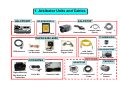
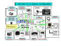
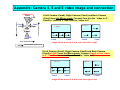
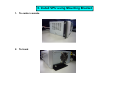
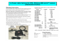
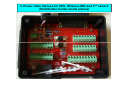
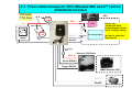
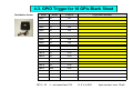
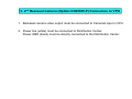
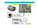
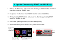
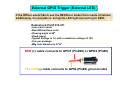
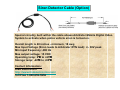
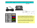
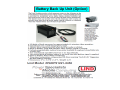
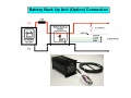
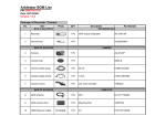
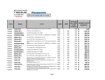
Arbitrator 360
Hardware Installation ver 2.4
(Distribution Center version)
1. Arbitrator Units and Cables
AG-CPD20P
Recorder (VPU)
AG-CK10P
RP-SDW32GP1K
32GB SDHC Card
Camera
Camera Mount
Camera Cable
(Short)
Camera Cable
(Long)
TT-ARBM56P06
PAPDC2462-2859
3rd-6th Camera
GPS Antenna
Power Cable
for Recorder
Power
Distribution Box
A360-WLSAP-BWT
External GPIO
Trigger Cable
LAN Cable
(Crossing type)
OPTIONS
CCR24PNA
AG-RCP30P
Digital Wireless
Mic Reciever &
Transmitter
In Car Mic
Receiver Cable
Control Panel
Control Panel
Cable
AP-WiFi-Modem
CN258IR-P
2nd Backseat
Camera
2. Arbitrator in-car System Configuration
Control Panel
(Option)
Camera 2
(backseat)
(Option)
Toughbook
(In car PC)
AG-RCP30P
Front End
Application
CN258IR-P
Video Out 1
for LPR/
Monitor etc
Option Camera Examples
Camera 3 (LPR)
Camera 4 (Left)
Camera 5 (Right)
Camera 6 (Back)
Ethernet
Cable for
Wired
Upload
Cable Kit
VPU
AG-CR13P
AG-CPD20P
GPS
Antenna
Use the mirror mode for Camera 4,
5 and 6.
If no mirror mode for these,
connect Camera 4 (Left) to Video 5
and Camera 5 (Right) to Video 4.
Power
Distribution Box
2nd/3rd
WMIC
RX/TX
(Option)
RX/TX
In Car Mic
Camera 1
(Front)
WMIC RX/TX
AG-CK10P
CCR24PNA
Car Battery
12V/24V
16 Triggers
(Siren/Light
Bar/Brake/
WMIC etc)
Serial (RS-232C)
for Radar Gun
From 3rd
Vendor
AP-WiFiModem
A360-WLSAP-BWT
Appendix: Camera 4, 5 and 6 video image and connection
1 (Camera 1)
Front
3
LPR
Cam4
Left
If Left Camera (Cam4), Right Camera (Cam5) and Back Camera
(Cam6) have the Mirror mode, Connect Cam 4 to the “video in 4”,
Cam5 to “video in 5” and Cam6 to “video in 6”
Cam5
Right
1, 2 or 3
1, 2 or 3
2
R-Seat
4
Cam6
Back
6
5
4
6
5
Cam4
Cam4
Cam5
Cam5
Image will be moved 4, 6, 5 in order from left to right.
Officer Walking Direction
If Left Camera (Cam4), Right Camera (Cam5) and Back Camera
(Cam6) do NOT have the Mirror mode, Connect Cam 4 to the “video
in 5”, Cam5 to “video in 4” and Cam6 to “video in 6”
1, 2 or 3
4
Cam5
6
1, 2 or 3
5
Cam4
4
Cam5
6
5
Cam4
Image will be moved 5, 6, 4 in order from right to left.
3. Install VPU using Mounting Bracket
1. To center console
2. To trunk
4. Power cable harness for VPU, Wireless MIC and 2nd camera
(Distribution Center)
4. Power cable harness for VPU, Wireless MIC and 2nd camera
(Distribution Center inside picture)
4-1. Power cable harness for VPU, Wireless MIC and 2nd camera
(Distribution Center)
10A fuse
7.5A fuse
VPU
Fuse
10A
RED
(+)
power
■
ACC switch
Car Battery
12V/24V
Fuse
7.5A
Clock
Please set
“Power Off Time”
to be minimum 10 min
in FE “Config” setting
Power sw
WHITE
BLACK
(-)
Recording engine
signal(SA)
■
in order to close the
file properly.
■
1A in-line
fuse
Receiver (RX) Cable
RED #1
Power GND #2
Trigger GND #5
WMIC Receiver (RX)
WHITE
BLACK
2nd ~6th Camera
4-2. GPIO Trigger for 16 GPIs
Distribution Center
Signal
Remark
J1 Input #
Trigger Name (Example)
GPI 1
In
J1-1
Wireless Mic
GPI 2
In
J1-2
Light Bar
GPI 3
In
J1-3
Brake Indicator
GPI 4
In
J1-4
Siren Indicator
GPI 5
In
J1-5
Gun Lock
GPI 6
In
J1-6
Wireless Mic Active indicator
(H)
GPI 7
In
J1-7
Wireless Mic Mute indicator
(H)
GPI 8
In
J1-8
Other
GPI 9
In
J1-9
Other
GPI 10
In
J1-10
Other
GPI 11
In
J1-11
Other
GPI 12
In
J1-12
Other
GPI 13
In
J1-13
Other
GPI 14
In
J1-14
Other
GPI 15
In
J1-15
Own(REC) / TGT(REC) (when connecting Radar/GPS)
GPI 16
In
J1-16
Own(REC) / TGT(REC) (when connecting Radar/GPS)
GPO 1
Out
J1-21
Open Emitter (Rec, Error, Rec+Eror: Active 5V 15mA)
GPO 2
Out
J1-22
Open Emitter (Rec, Error, Rec+Eror: Active 5V 15mA)
GPO 3
Out
J1-23
Open Collector (Rec : Active L)
GPO 4
Out
J1-24
+5V out
GPI 1~16
L : not more than1.0V
H: 4 V to 28V
Input current max. 12mA
4-3. GPIO Trigger for 16 GPIs Blank Sheet
Distribution Center
Signal
Remark
J1 Input #
GPI 1
In
J1-1
GPI 2
In
J1-2
GPI 3
In
J1-3
GPI 4
In
J1-4
GPI 5
In
J1-5
GPI 6
In
J1-6
GPI 7
In
J1-7
GPI 8
In
J1-8
GPI 9
In
J1-9
GPI 10
In
J1-10
GPI 11
In
J1-11
GPI 12
In
J1-12
GPI 13
In
J1-13
GPI 14
In
J1-14
GPI 15
In
J1-15
GPI 16
In
J1-16
GPO 1
Out
J1-21
GPO 2
Out
J1-22
GPO 3
Out
J1-23
GPO 4
Out
J1-24
GPI 1~16
L : not more than1.0V
Trigger Name (Example)
H: 4 V to 28V
Input current max. 12mA
5. Wireless Mic Receiver Connection to VPU
1. Besides power and GND lines, there are three trigger lines.
See the chart and connect each line properly to the GPI inputs.
2. Trigger GND (#5) and power GND (#2) must be directly connected
to the Distribution Center.
5-1. Wireless Mic Receiver Connection to VPU
Distribution Center
Digital Wireless Mic
Receiver & Transmitter
DC Power (RED) #1
To J3 + terminal
Power GND (Black) #2
Receiver (RX)
To J3 - terminal
Recording Trigger (Brown) #7
TX indication (Orange) #6
Mute indication (white) #8
-> Distribution Center
To
Receiver
Jack
Trigger GND (Black) #5
To Distribution Center
Receiver (RX)
Cable
To
Audio In 1
VPU (Rear)
In Car Mic
2nd / 3rd Wireless Mic
Receiver (optional)
To Audio In 2
To Audio In 3 and 4
6. 2nd Rearseat Camera (Option:CN258IR-P) Connection to VPU
1. Backseat camera video output must be connected to Camera2 input in VPU
2. Power line (white) must be connected to Distribution Center.
Power GND (black) must be directly connected to the Distribution Center.
6-1. 2nd backseat Camera (Option:CN258IR-P) Connection to VPU
2nd Camera
2nd Camera
Cable
Distribution Center
White to J3 + terminal
Black J3 - terminal
Yellow to Camera 2
VPU (Rear)
7. Control Panel (Option: AG-RCP30P) Connection to VPU
Control Panel
Control Panel and Cable
VPU (Rear)
8. Update Firmware by SDHC card/USB key
1. Put vup file (firmware) right under root directory in SDHC card or USB drive.
Don’t put any other folders / files.
2. Keep open the door and insert SDHC card or connect USB drive.
3. While pressing STOP button, turn power on, then keep pressing STOP
button for another 30 sec.
4. VPU starts updating firmware, see the LEDs (below).
5. Once it’s finished (takes about 4 min), VPU reboots itself.
Continuous
lighting
(Red LED)
Blinking
(Green LED))
Keep
open
Continuous lighting
(Red LED)
Appendix
External GPIO Trigger (External LED)
If the Officer would like to see the REC/Error status from inside of vehicle
additionally, it is possible to set up the LED light connecting to GPIO
Radioshack Part# 276-011
•Lens size is 5mm
•Red diffused lens color
•Viewing angle is 60°
°
•30mA (max)
•Typical Voltage is 12, with a maximum voltage of 12V
•One per package
•Mfg hole diameter is 5/16"
RED (+) cable connects to GPO1 (Pin#25) or GPO2 (Pin#8)
YELLOW (-) cable connects to GPIO (Pin#9) ground cable
Siren Detector Cable (Option)
Special circuitry built within the cable allows Arbitrator Mobile Digital Video
System to activate when police vehicle siren is turned on.
Overall length is 40 inches - minimum, 18 awg
Max Input Voltage (Siren leads to Arbitrator RTN lead): +/- 30V peak
Min input frequency: 400 Hz
Max output voltage: 15 VDC
Operating temp: 0℃
℃ to +65℃
℃
Storage temp: -40℃
℃ to +85℃
℃
Contact Information:
LIND Electronics
http://www.lindelectronics.com/
Toll Free 1-800-659-5956
G-Force Sensor (Option) Connection
TGS-3DP
Black (GND: - ):
Connect to the Distribution Center
Red (BATT: +):
Connect to the Distribution Center
<Power Cable>
<Trigger Cable>
Connect each cable to the
Distribution Center
External GPIO Trigger Connection to G-Force Sensor (Option)
TGS-3DP
Pin #
Description
Cable Color
1
FLIP Out
White
2
RIGHT Out
Orange
3
LEFT Out
Blue
4
REAR Out
Red
5
FRONT Out
Brown
6
REC Out
Green
7
GND
Yellow
8
GND
Black
9
GND
Gray
If you have 5 trigger inputs available on Distribution
Center, connect Pin#1-5 with the center so that VPU can
start recording by the impact from any 6 directions with
indication on screen of Arb360FE and/or Control Panel.
If you have only 1 trigger input available on Distribution
Center, connect Pin #6 to start recording by the trigger
regardless of which direction the impact comes from.
All GND(3 pins) should be connected.
Battery Back Up Unit (Option)
Battery Back Up Unit (Option) Connection