1
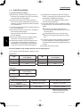
TECHNICAL DATA
&
SERVICE MANUAL
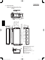
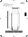
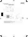
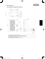
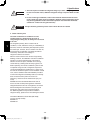
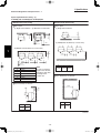
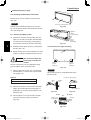
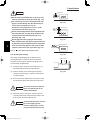
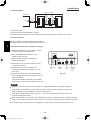
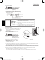
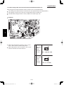
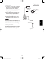
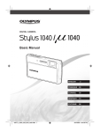
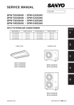
Outdoor Unit
Indoor Unit
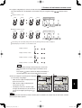
Shows S-26PU1U6
Shows U-26PE1U6
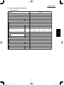
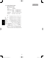
Model No.
Outdoor Units
Type
U
Outdoor Units
26
36
42
Remarks
U-26PE1U6
U-36PE1U6
U-42PE1U6
Cooling/Heating
U-26PS1U6
U-36PS1U6
U-42PS1U6
Cooling
26
36
42
S-36PU1U6
S-42PU1U6
Single
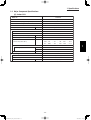
Indoor Units
Type
Indoor Units Type
U1
4-Way Cassette
S-26PU1U6
K1
Wall Mounted
S-26PK1U6
T1
Ceiling
S-26PT1U6
S-36PT1U6
F1
Low Silhouette Duct
S-26PF1U6
S-36PF1U6
85464849303001
SM830203-01_PAC-i_US-letter.indb1 1
Remarks
with Wired Remote Controller: CZ-RTC2
with Wireless Remote Controller: CZ-RWSK1U
S-42PT1U6
with Wired Remote Controller: CZ-RTC2
with Wired Remote Controller: CZ-RTC2
REFERENCE NO. SM830203-01
2012/01/20 13:46:35
IMPORTANT!
Please Read Before Starting
This air conditioning system meets strict safety and operating standards. As the installer or service person, it is an
important part of your job to install or service the system so
it operates safely and efficiently.
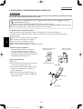
When Transporting
Be careful when picking up and moving the indoor and
outdoor units. Get a partner to help, and bend your knees
when lifting to reduce strain on your back. Sharp edges or
For safe installation and trouble-free operation, you must: thin aluminum fins on the air conditioner can cut your
fingers.
Carefully read this instruction booklet before beginning.
When Installing…
Follow each installation or repair step exactly as shown.
Observe all local, state, and national electrical codes.
Pay close attention to all warning and caution notices
given in this manual.
This symbol refers to a hazard or
unsafe practice which can result
WARNING
in severe personal injury or death.
CAUTION
Select an installation location which is rigid and strong
enough to support or hold the unit, and select a location
for easy maintenance.
…In a Room
Properly insulate any tubing run inside a room to prevent
“sweating” that can cause dripping and water damage to
walls and floors.
Keep the fire alarm and the air outlet at least
CAUTION
5 feet away from the unit.
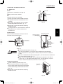
…In Moist or Uneven Locations
Use a raised concrete pad or concrete blocks to provide
a solid, level foundation for the outdoor unit. This prevents
water damage and abnormal vibration.
…In an Area with High Winds
Securely anchor the outdoor unit down with bolts and a
metal frame. Provide a suitable air baffle.
…In a Snowy Area (for Heat Pump-type Systems)
Install the outdoor unit on a raised platform that is higher
than drifting snow. Provide snow vents.
This symbol refers to a hazard or
unsafe practice which can result
in personal injury or product or
property damage.
If Necessary, Get Help
These instructions are all you need for most installation
sites and maintenance conditions. If you require help for a
special problem, contact our sales/service outlet or your
certified dealer for additional instructions.
In Case of Improper Installation
The manufacturer shall in no way be responsible for
improper installation or maintenance service, including failure to follow the instructions in this document.
When Connecting Refrigerant Tubing
• Ventilate the room well, in the event that is refrigerant
gas leaks during the installation. Be careful not to allow
contact of the refrigerant gas with a flame as this will
cause the generation of poisonous gas.
SPECIAL PRECAUTIONS
WARNING
When Wiring
• Keep all tubing runs as short as possible.
ELECTRICAL SHOCK CAN CAUSE
SEVERE PERSONAL INJURY OR DEATH.
ONLY A QUALIFIED, EXPERIENCED
ELECTRICIAN SHOULD ATTEMPT TO
WIRE THIS SYSTEM.
• Use the flare method for connecting tubing.
• Apply refrigerant lubricant to the matching surfaces of
the flare and union tubes before connecting them, then
tighten the nut with a torque wrench for a leak-free connection.
• Check carefully for leaks before starting the test run.
• Do not supply power to the unit until all wiring and tubing
are completed or reconnected and checked.
• Highly dangerous electrical voltages are used in this
system. Carefully refer to the wiring diagram and these
instructions when wiring. Improper connections and inadequate grounding can cause accidental injury or death.
WARNING
• Ground the unit following local electrical codes.
• Connect all wiring tightly. Loose wiring may cause overheating at connection points and a possible fire hazard.
• When performing piping work do not
mix air except for specifled refrigerant
(R410A) in refrigeration cycle. It
causes capacity down, and risk of
explosion and injury due to high
tension inside the refrigerant cycle.
• Refrigerant gas leakage may cause
fire.
• Do not add or replace refrigerant
other than specified type.
It may cause product damage,
burst and injury etc.
• To prevent possible hazards from insulation failure,
the unit must be grounded.
• Do not leak refrigerant while piping work for an installation
or re-installation, and while repairing refrigeration parts.
Handle liquid refrigerant carefully as it may cause frostbite.
i
SM830203-01_PAC-i_US-letter.indbII II
2012/01/20 13:46:35
When Servicing
CAUTION
• Turn the power OFF at the main power box (mains)
before opening the unit to check or repair electrical
parts and wiring.
• Keep your fingers and clothing away from any moving
parts.
• Clean up the site after you finish, remembering to check
that no metal scraps or bits of wiring have been left
inside the unit being serviced.
WARNING
NOTICE
• Do not clean inside the indoor and
outdoor units by users. Engage
authorized dealer or specialist for
cleaning.
• In case of malfunction of this
appliance, do not repair by yourself.
Contact to the sales dealer or service
dealer for a repair.
• Do not touch the air inlet or the
sharp aluminum fins of the
outdoor unit. You may get injured.
• Ventilate any enclosed areas when
installing or testing the refrigeration
system. Escaped refrigerant gas, on
contact with fire or heat, can produce
dangerously toxic gas.
• Confirm after installation that no
refrigerant gas is leaking. If the gas
comes in contact with a burning stove,
gas water heater, electric room heater
or other heat source, it can cause the
generation of poisonous gas.
Others
CAUTION
• Do not touch the air inlet or the
sharp aluminum fins of the
outdoor unit. You may get injured.
• Do not sit or step on the unit,
you may fall down accidentally.
• Do not stick any object into the
FAN CASE.
You may be injured and the
unit may be damaged.
• This device complies with part 15 of the FCC Rules.
Operation is subject to the following two conditions:
(1) This device may not cause harmful interference, and (2) this device must accept any interference
received, including interference that may cause undesired operation.
• This equipment has been tested and found to comply with the limits for a Class B digital device,
pursuant to part 15 of the FCC Rules.
These limits are designed to provide reasonable protection against harmful interference in a residential
installation. This equipment generates, uses and can radiate radio frequency energy and, if not installed
and used in accordance with the instructions, may cause harmful interference to radio communications.
However, there is no guarantee that interference will not occur in a particular installation. If this
equipment does cause harmful interference to radio or television reception, which can be determined
by turning the equipment off and on, the user is encouraged to try to correct the interference by one or
more of the following measures:
• Reorient or relocate the receiving antenna.
• Increase the separation between the equipment and receiver.
• Connect the equipment into an outlet on a circuit different from that to which the receiver is connected.
• Consult the dealer or an experienced radio/TV technician for help.
• FCC Caution: To assure continued compliance, follow the attached installation instructions.
Any changes or modifications not expressly approved by the party responsible for compliance could
void the user’s authority to operate this equipment.
Check of Density Limit
The room in which the air conditioner is to be
installed requires a design that in the event of refrigerant gas leaking out, its density will not exceed a set
limit.
The refrigerant (R410A), which is used in the air conditioner, is safe, without the toxicity or combustibility of ammonia,
and is not restricted by laws imposed to protect the ozone
layer. However, since it contains more than air, it poses the
risk of suffocation if its density should rise excessively. Suffocation from leakage of refrigerant is almost non-existent.
With the recent increase in the number of high density
buildings, however, the installation of multi air conditioner
systems is on the increase because of the need for effective use of floor space, individual control, energy conservation by curtailing heat and carrying power, etc.
Most importantly, the multi air conditioner system is able
to replenish a large amount of refrigerant compared to
conventional individual air conditioners. If a single unit of
the multi air conditioner system is to be installed in a
small room, select a suitable model and installation procedure so that if the refrigerant accidentally leaks out, its
density does not reach the limit (and in the event of an
emergency, measures can be made before injury can
occur).
ASHRAE and the International Mechanical Code of the
ICC as well as CSA provide guidance and define safeguards related to the use of refrigerants, all of which define
a Refrigerant Concentration Level (RCL) of 25 pounds
per 1,000 cubic feet for R410A refrigerant.
For additional guidance and precautions related to
refrigerant safety, please refer to the following documents:
International Mechanical Code 2009 (IMC-2009)
(or more recently revised)
ASHRAE 15
ASHRAE 34
ii
SM830203-01_PAC-i_US-letter.indbIII III
2012/01/20 13:46:35
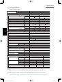
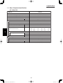
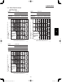
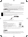
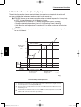
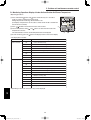
Precautions for Installation Using New Refrigerant
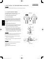
1. Care regarding tubing
1-1. Process tubing
Material: Use C1220 phosphorous deoxidized copper specified in JIS H3300 “Copper and Copper Alloy Seamless
Pipes and Tubes.”
Tubing size: Be sure to use the sizes indicated in the table below.
Use a tube cutter when cutting the tubing, and be sure to remove any flash. This also applies to distribution joints
(optional).
When bending tubing ø5/8" or smaller, use a bending radius that is 4 times the outer diameter of the tubing or larger.
CAUTION
Use sufficient care in handling the tubing. Seal the tubing ends with
caps or tape to prevent dirt, moisture, or other foreign substances
from entering. These substances can result in system malfunction.
Unit: inch
Material
Copper tube
O
Outer diameter
1/4
3/8
1/2
5/8
Wall thickness
t0.032
t0.032
t0.032
t0.04
1-2. Prevent impurities including water, dust and oxide from entering the tubing. Impurities can cause R410A
refrigerant deterioration and compressor defects. Due to the features of the refrigerant and refrigerating machine
oil, the prevention of water and other impurities becomes more important than ever.
2. Be sure to recharge the refrigerant only in liquid form.
2-1. Since R410A is a non-azeotrope, recharging the refrigerant in gas form can lower performance and cause
defects of the unit.
2-2. Since refrigerant composition changes and performance decreases when gas leaks, collect the remaining
refrigerant and recharge the required total amount of new refrigerant after fixing the leak.
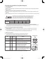
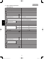
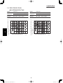
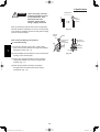
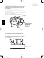
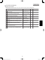
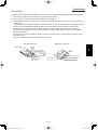
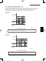
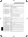
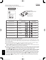
3. Different tools required
3-1. Tool specifications have been changed due to the characteristics of R410A.
Some tools for R22- and R407C-type refrigerant systems cannot be used.
Manifold gauge
Item
New
tool?
R407C tools
compatible
with R410A?
Manifold gauge
Yes
No
Types of refrigerant, refrigerating machine oil, and
pressure gauge are different.
Charge hose
Yes
No
To resist higher pressure, material must be changed.
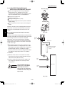
Vacuum pump
Yes
Yes
Use a conventional vacuum pump if it is equipped
with a check valve. If it has no check valve,
purchase and attach a vacuum pump adapter.
Leak detector
Yes
No
Leak detectors for CFC and HCFC that
react to chlorine do not function because
R410A contains no chlorine. Leak detector
for HFC134a can be used for R410A.
Flaring oil
Yes
No
Remarks
Vacuum pump
Outlet
Inlet
For systems that use R22, apply mineral oil (Suniso oil)
to the flare nuts on the tubing to prevent refrigerant
leakage. For machines that use R407C or R410A, apply
synthetic oil (ether oil) to the flare nuts.
* Using tools for R22 and R407C and new tools for R410A together can cause defects.
iii
SM830203-01_PAC-i_US-letter.indbIV IV
2012/01/20 13:46:35
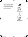
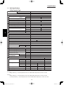
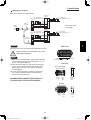
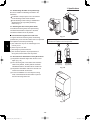
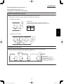
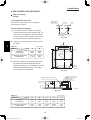
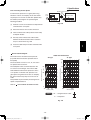
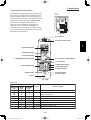
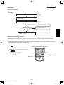
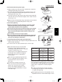
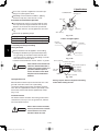
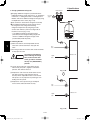
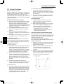
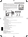
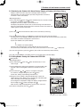
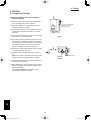
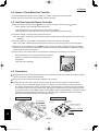
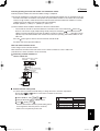
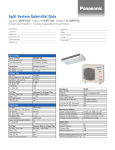
Configuration and characteristics of cylinders
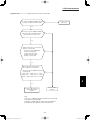
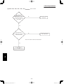
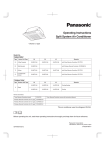
3-2. Use R410A exclusive cylinder only.
When charging with a refrigerant cylinder, use an
electronic scale for charging refrigerant. In this case,
if the volume of refrigerant in the cylinder becomes
less than 20% of the fully-charged amount, the
composition of the refrigerant starts to change. Thus,
do not use the refrigerant if the amount in the charging
cylinder is less than 20%. Also, charge the minimum
necessary amount to the charging cylinder before
using it to charge the air conditioning unit.
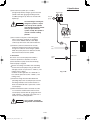
Valve
Liquid
Single valve
Charge liquid refrigerant with
cylinder in up-side-down position.
Fig. 1
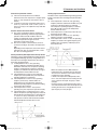
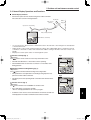
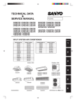
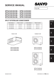
Valve
Liquid
Single valve (with siphon tube)
Charge with cylinder in normal position.
Fig. 2
iv
SM830203-01_PAC-i_US-letter.indbV V
2012/01/20 13:46:35
Contents
Section 1: SPECIFICATIONS ..................................................................................................... 1-1
1-1 Unit SpecifIcations .............................................................................................. 1-2
1-2 Major Component SpecifIcations ...................................................................... 1-20
1-3 Other Component SpecifIcations ...................................................................... 1-35
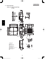
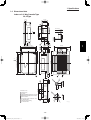
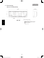
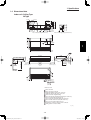
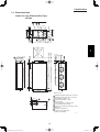
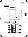
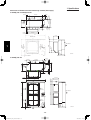
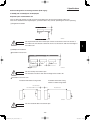
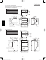
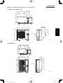
1-4 Dimensional Data.............................................................................................. 1-38
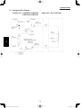
1-5 Refrigerant Flow Diagram ................................................................................. 1-48
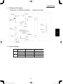
1-6 Operating Range............................................................................................... 1-49
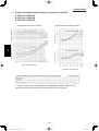
1-7 Capacity Correction Graph According to Temperature Condition ..................... 1-50
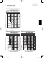
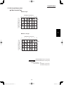
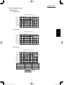
1-8 Noise Criterion Curves...................................................................................... 1-51
1-9 Increasing the Fan Speed ................................................................................. 1-56
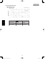
1-10 Air throw distance chart .................................................................................... 1-57
1-11 ELECTRICAL WIRING ..................................................................................... 1-60
1-12 Installation Instructions ..................................................................................... 1-63
1-13 HOW TO PROCESS TUBING......................................................................... 1-118
1-14 LEAK TEST, EVACUATION AND ADDITIONAL REFRIGERANT CHARGE .... 1-122
Section 2: PROCESSES AND FUNCTIONS.............................................................................. 2-1
2-1 Room Temperature Control ................................................................................. 2-2
2-2 Cold Draft Prevention (Heating Cycle) ................................................................ 2-4
2-3 Automatic Fan Speed (Indoor Unit)..................................................................... 2-5
2-4 Control Functions ................................................................................................ 2-6
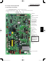
2-5 Outdoor Unit Control PCB................................................................................... 2-9
2-6 Outdoor Unit Control PCB (CR-CH4272R) ....................................................... 2-10
Section 3: ELECTRICAL DATA .................................................................................................. 3-1
3-1 Indoor Units ........................................................................................................ 3-2
3-2 Outdoor Units .................................................................................................... 3-10
Section 4: SERVICE PROCEDURES ......................................................................................... 4-1
4-1 Meaning of Alarm Messages .............................................................................. 4-2
4-2 Symptoms and Parts to Inspect .......................................................................... 4-5
4-3 Details of Alarm Messages ................................................................................. 4-8
4-4 Table of Thermistor Characteristics .................................................................. 4-14
Section 5: OUTDOOR UNIT MAINTENANCE REMOTE CONTROL ........................................ 5-1
5-1 Overview ............................................................................................................. 5-2
5-2 Functions ............................................................................................................ 5-2
5-3 Normal Display Operations and Functions ......................................................... 5-3
5-4 Monitoring Operations: Display of Indoor Unit and Outdoor Unit Sensor
Temperatures ...................................................................................................... 5-6
5-5 Monitoring the Outdoor Unit Alarm History: Display of Outdoor Unit
Alarm History ...................................................................................................... 5-7
5-6 Setting Modes: Setting the Outdoor Unit EEPROM ............................................ 5-7
Section 6: TSET RUN ................................................................................................................. 6-1
6-1 Preparing for Test Run ........................................................................................ 6-2
6-2 Caution ............................................................................................................... 6-3
6-3 Test Run Procedure ............................................................................................ 6-3
6-4 Items to Check Before the Test Run.................................................................... 6-4
6-5 Test Run Using the Remote Controller ............................................................... 6-4
6-6 Precautions ......................................................................................................... 6-4
6-7 Table of Self-Diagnostic Functions and Corrections (U1, K1, T1, F1 Type) ........ 6-5
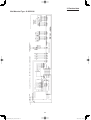
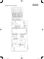
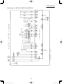
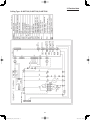
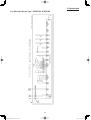
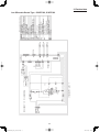
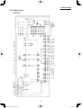
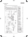
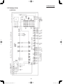
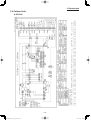
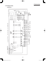
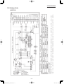
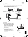
6-8 Examples of Wiring Diagrams ............................................................................. 6-6
vi
SM830203-01_PAC-i_US-letter.indbVI VI
2012/01/20 13:46:35
1. SPECIFICATIONS
1-1.
Unit Specifications.................................................................................................... 1-2
1-2.
Major Component Specifications .......................................................................... 1-20
1-3.
Other Component Specifications .......................................................................... 1-35
1-4.
Dimensional Data .................................................................................................... 1-38
1-5.
Refrigerant Flow Diagram ...................................................................................... 1-48
1-6.
Operating Range ..................................................................................................... 1-49
1-7.
Capacity Correction Graph According to Temperature Condition ..................... 1-50
1-8.
Noise Criterion Curves ........................................................................................... 1-51
1-9.
Increasing the Fan Speed ...................................................................................... 1-56
1-10. Air throw distance chart ......................................................................................... 1-57
1-11. ELECTRICAL WIRING ............................................................................................. 1-60
1-12. Installation Instructions .......................................................................................... 1-63
1
Outdoor Unit
1. Tubing Size ....................................................................................................................................... 1-63
2. Check of density limit ........................................................................................................................ 1-64
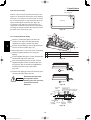
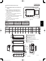
3. SELECTING THE INSTALLATION SITE ......................................................................................... 1-65
4. HOW TO INSTALL THE OUTDOOR UNIT ....................................................................................... 1-74
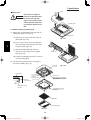
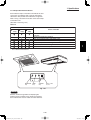
Indoor Unit
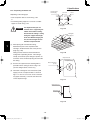
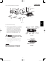
5. SELECTING THE INSTALLATION SITE ......................................................................................... 1-75
6. HOW TO INSTALL THE INDOOR UNIT ........................................................................................... 1-76
7. HOW TO INSTALL THE WIRELESS REMOTE CONTROLLER .................................................... 1-100
TENTATIVE
8. HOW TO INSTALL THE TIMER WIRED REMOTE CONTROLLER .............................................. 1-118
1-13. HOW TO PROCESS TUBING ................................................................................. 1-118
1-14. LEAK TEST, EVACUATION AND ADDITIONAL REFRIGERANT CHARGE ........1-122
1-1
SM830203-01_PAC-i_US-letter.indb1 1
2012/01/30 12:53:17
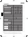
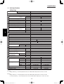
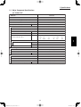
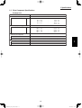
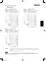
1. Specifications
1-1 Unit Specifications
4-Way Cassette Type
MODEL No.
1
Indoor Unit
S-26PU1U6
Outdoor Unit
U-26PE1U6
230 - 208 V / 1 Phase / 60 Hz
POWER SOURCE
Cooling
Heating
PERFORMANCE
Capacity * [minimum~muximum]
BTU / h 24,800 [9,500~24,800]
29,800 [8,000~29,800]
(17˚F)**
BTU / h
18,300
Moisture removal (High)
Pints / h
8.1
Air circulation (H / M / L) 230 V
CFM
710 / 530 / 450
in. WG
External Static Pressure
S.E.E.R. / H.S.P.F. (Region 4)
BTU / Wh
14.1
9.6
ELECTRICAL RATINGS
Voltage rating
V
230
208
230
208
Available voltage range
V
VAC 187 - 253
VAC 187 - 253
A
15.6
17.3
14.8
16.4
Max.Running amperes*
Power input
W
2,920
2,920
2,790
2,790
(17˚F)**
W
2,200
2,200
Back-up Heater
kW
Maximum overcurrent protection (Indoor/Outdoor)
A
15 / 30
FEATURES
Controls
Microprocessor
Low ambient control
Built-in 0˚F
Fan speeds Indoor / Outdoor
3 and Automatic control / Variable
CZ-RTC2
Wired Remote Controller
CZ-RWSU1U
Optional Wireless Remote Controller
Air deflection (Horizontal / Vertical )
/ Automatic (Vertical )
Air filter
Washable, long life (2,500 hr)
Max.head 2-33/64 in. above drain connection (25A , OD32mm)
Drain pump (Drain connection)
Compressor
Rotary
Indoor - Hi/Me/Lo
dB - A
38 / 35 / 31
Operation sound
Outdoor - Hi
dB - A
49
Refrigerant control
Electronic Expansion Valve (MOV)
REFRIGERANT TUBING
Limit of tubing length
ft. (m)
165 (50)
Limit of tubing length at shipment
ft. (m)
10~100 (3~30)
Limit of elevation difference
ft. (m)
Outdoor unit is higher than indoor unit : 100 (30)
between the two units
ft. (m)
Outdoor unit is lower than indoor unit : 50 (15)
Refrigerant tube
Narrow tube
in. (mm)
3 / 8 (6.35)
outer diameter
Wide tube
in. (mm)
5 / 8 (15.88)
Refrigerant amount at shipment
lbs. (kg)
4.2 (1.9) - R410A
Indoor unit (Include panel)
Outdoor unit
DIMENSIONS & WEIGHT
Unit dimensions
Height
in. (mm)
13-5/16 (338)
30- 23/32 (780)
Width
in. (mm)
33-55/64 (860)
37 (940)
Depth
in. (mm)
33-55/64 (860)
13- 3/8 (340)
Package dimensions
Body
Panel
Outdoor unit
Height
in. (mm) 11-9/64 (283)
4-3/32 (104)
34- 31/32 (888)
Width
in. (mm)
32-7/8 (835)
37-61/64 (964) 39- 31/32 (1,015)
Depth
in. (mm) 33-9/32 (845)
39-21/64 (999)
16- 3/32 (409)
Net weight
lbs. (kg)
49 (22)
11 (5)
128 (58)
Shipping weight
lbs. (kg)
57 (26)
18 (8)
148 (67)
Shipping volume
cu.ft. (m 3 )
7.1 (0.200)
3.6 (0.100)
13.0 (0.369)
DATA SUBJECT TO CHANGE WITHOUT NOTICE.
Cooling:
Rating conditions (*) : Room temperature 80 °F DB / 67 °F WB, Ambient temperature 95 °F DB / 75 °F WB
Heating:
Rating conditions (*) : Room temperature 70 °F DB / 60 °F WB, Ambient temperature 47 °F DB / 43 °F WB
Low temp conditions (**) : Room temperature 70 °F DB / 60 °F WB, Ambient temperature 17 °F DB / 15 °F WB
1-2
SM830203-01_PAC-i_US-letter.indb2 2
2012/01/19 22:39:16
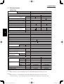
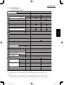
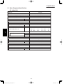
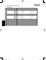
1. Specifications
1-1 Unit Specifications
4-Way Cassette Type
MODEL No.
Indoor Unit
S-36PU1U6
Outdoor Unit
U-36PE1U6
230 - 208 V / 1 Phase / 60 Hz
POWER SOURCE
Cooling
Heating
PERFORMANCE
Capacity * [minimum~muximum]
BTU / h 32,600 [9,500~32,600]
37,600 [8,000~37,600]
(17˚F)**
BTU / h
20,000
Moisture removal (High)
Pints / h
10.6
Air circulation (H / M / L) 230 V
CFM
1050 / 840 / 720
in. WG
External Static Pressure
S.E.E.R. / H.S.P.F. (Region 4)
BTU / Wh
14.6
8.4
ELECTRICAL RATINGS
Voltage rating
V
230
208
230
208
Available voltage range
V
VAC 187 - 253
VAC 187 - 253
Max. Running amperes*
A
18.7
20.7
15.9
17.6
Power input
W
3,950
3,950
3,350
3,350
(17˚F)**
W
2,450
2,450
Back-up Heater
kW
Maximum overcurrent protection (Indoor/Outdoor)
A
15 / 35
FEATURES
Controls
Microprocessor
Low ambient control
Built-in 0˚F
Fan speeds Indoor / Outdoor
3 and Automatic control / Variable
Wired Remote Controller
CZ-RTC2
Optional Wireless Remote Controller
CZ-RWSU1U
/ Automatic (Vertical )
Air deflection (Horizontal / Vertical )
Air filter
Washable, long life (2,500 hr)
Max.head 2-33/64 in. above drain connection (25A , OD32mm)
Drain pump (Drain connection)
Compressor
Rotary
Indoor - Hi/Me/Lo
dB - A
44 / 37 / 33
Operation sound
Outdoor - Hi
dB - A
52
Refrigerant control
Electronic Expansion Valve (MOV)
REFRIGERANT TUBING
Limit of tubing length
ft. (m)
165 (50)
Limit of tubing length at shipment
ft. (m)
10~100 (3~30)
Limit of elevation difference
ft. (m)
Outdoor unit is higher than indoor unit : 100 (30)
between the two units
ft. (m)
Outdoor unit is lower than indoor unit : 50 (15)
Refrigerant tube
Narrow tube
in. (mm)
3 / 8 (6.35)
outer diameter
Wide tube
in. (mm)
5 / 8 (15.88)
Refrigerant amount at shipment
lbs. (kg)
6.2 (2.8) - R410A
Indoor unit (Include panel)
Outdoor unit
DIMENSIONS & WEIGHT
Unit dimensions
Height
in. (mm)
14-31/64 (368)
30- 23/32 (780)
Width
in. (mm)
45-9/32 (1,150)
37 (940)
Depth
in. (mm)
33-55/64 (860)
13- 3/8 (340)
Package dimensions
Body
Panel
Outdoor unit
Height
in. (mm) 12-13/32 (315)
4-3/32 (104)
34- 31/32 (888)
Width
in. (mm) 44-19/64 (1,125) 49-31/64 (1,257) 39- 31/32 (1,015)
Depth
in. (mm) 33-9/32 (845)
39-21/64 (999)
16- 3/32 (409)
Net weight
lbs. (kg)
60 (27)
16 (7)
143 (65)
Shipping weight
lbs. (kg)
71 (32)
22 (10)
161 (73)
Shipping volume
cu.ft. (m 3 )
10.6 (0.299)
4.6 (0.131)
13.0 (0.369)
DATA SUBJECT TO CHANGE WITHOUT NOTICE.
1
Cooling:
Rating conditions (*) : Room temperature 80 °F DB / 67 °F WB, Ambient temperature 95 °F DB / 75 °F WB
Heating:
Rating conditions (*) : Room temperature 70 °F DB / 60 °F WB, Ambient temperature 47 °F DB / 43 °F WB
Low temp conditions (**) : Room temperature 70 °F DB / 60 °F WB, Ambient temperature 17 °F DB / 15 °F WB
1-3
SM830203-01_PAC-i_US-letter.indb3 3
2012/01/19 22:39:17
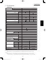
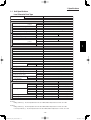
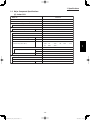
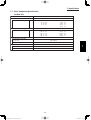
1. Specifications
1-1 Unit Specifications
4-Way Cassette Type
MODEL No.
1
Indoor Unit
S-42PU1U6
Outdoor Unit
U-42PE1U6
230 - 208 V / 1 Phase / 60 Hz
POWER SOURCE
Cooling
Heating
PERFORMANCE
Capacity * [minimum~muximum]
BTU / h 39,500 [9,500~39,500]
48,000 [8,000~48,000]
(17˚F)**
BTU / h
31,800
Moisture removal (High)
Pints / h
12.6
Air circulation (H / M / L) 230 V
CFM
1050 / 840 / 720
in. WG
External Static Pressure
S.E.E.R. / H.S.P.F. (Region 4)
BTU / Wh
14.6
9.7
ELECTRICAL RATINGS
Voltage rating
V
230
208
230
208
Available voltage range
V
VAC 187 - 253
VAC 187 - 253
Max. Running amperes*
A
23.0
25.4
22.4
24.8
Power input
W
4,520
4,520
4,360
4,360
(17˚F)**
W
3,540
3,540
Back-up Heater
kW
Maximum overcurrent protection (Indoor/Outdoor)
A
15 / 40
FEATURES
Controls
Microprocessor
Low ambient control
Built-in 0˚F
Fan speeds Indoor / Outdoor
3 and Automatic control / Variable
Wired Remote Controller
CZ-RTC2
Optional Wireless Remote Controller
CZ-RWSU1U
/ Automatic (Vertical )
Air deflection (Horizontal / Vertical )
Air filter
Washable, long life (2,500 hr)
Max.head 2-33/64 in. above drain connection (25A , OD32mm)
Drain pump (Drain connection)
Compressor
Rotary
Indoor - Hi/Me/Lo
dB - A
45 / 38 / 34
Operation sound
Outdoor - Hi
dB - A
53
Refrigerant control
Electronic Expansion Valve (MOV)
REFRIGERANT TUBING
Limit of tubing length
ft. (m)
165 (50)
Limit of tubing length at shipment
ft. (m)
10~100 (3~30)
Limit of elevation difference
ft. (m)
Outdoor unit is higher than indoor unit : 100 (30)
between the two units
ft. (m)
Outdoor unit is lower than indoor unit : 50 (15)
Refrigerant tube
Narrow tube
in. (mm)
3 / 8 (6.35)
outer diameter
Wide tube
in. (mm)
5 / 8 (15.88)
Refrigerant amount at shipment
lbs. (kg)
7.9 (3.6) - R410A
Indoor unit (Include panel)
Outdoor unit
DIMENSIONS & WEIGHT
Unit dimensions
Height
in. (mm)
14-31/64 (368)
48-7/16 (1,230 )
Width
in. (mm)
45-9/32 (1,150)
37 (940)
Depth
in. (mm)
33-55/64 (860)
13- 3/8 (340)
Package dimensions
Body
Panel
Outdoor unit
Height
in. (mm) 12-13/32 (315)
4-3/32 (104)
52-3/8 (1,330 )
Width
in. (mm) 44-19/64 (1,125) 49-31/64 (1,257) 39- 31/32 (1,015)
Depth
in. (mm) 33-9/32 (845)
39-21/64 (999)
16- 3/32 (409)
Net weight
lbs. (kg)
60 (27)
16 (7)
220 (100)
Shipping weight
lbs. (kg)
71 (32)
22 (10)
240 (109 )
Shipping volume
cu.ft. (m 3 )
10.6 (0.299)
4.6 (0.131)
19.5 (0.552 )
DATA SUBJECT TO CHANGE WITHOUT NOTICE.
Cooling:
Rating conditions (*) : Room temperature 80 °F DB / 67 °F WB, Ambient temperature 95 °F DB / 75 °F WB
Heating:
Rating conditions (*) : Room temperature 70 °F DB / 60 °F WB, Ambient temperature 47 °F DB / 43 °F WB
Low temp conditions (**) : Room temperature 70 °F DB / 60 °F WB, Ambient temperature 17 °F DB / 15 °F WB
1-4
SM830203-01_PAC-i_US-letter.indb4 4
2012/01/19 22:39:17
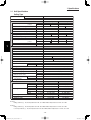
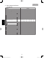
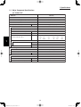
1. Specifications
1-1 Unit Specifications
4-Way Cassette Type
MODEL No.
Indoor Unit
S-26PU1U6
Outdoor Unit
U-26PS1U6
230 - 208 V / 1 Phase / 60 Hz
POWER SOURCE
Cooling
PERFORMANCE
Capacity * [minimum~muximum]
BTU / h
24,800 [9,500~24,800]
(17˚F)**
BTU / h
Moisture removal (High)
Pints / h
8.1
Air circulation (H / M / L) 230 V
CFM
710 / 530 / 450
in. WG
External Static Pressure
S.E.E.R. / H.S.P.F. (Region 4)
BTU / Wh
14.1
ELECTRICAL RATINGS
Voltage rating
V
230
208
Available voltage range
V
VAC 187 - 253
Max. Running amperes*
A
15.6
17.3
Power input
W
2,920
2,920
(17˚F)**
W
Back-up Heater
kW
Maximum overcurrent protection (Indoor/Outdoor)
A
15 / 30
FEATURES
Controls
Microprocessor
Low ambient control
Built-in 0˚F
Fan speeds Indoor / Outdoor
3 and Automatic control / Variable
Wired Remote Controller
CZ-RTC2
Optional Wireless Remote Controller
CZ-RWSU1U
Air deflection (Horizontal / Vertical )
/ Automatic (Vertical )
Air filter
Washable, long life (2,500 hr)
Max.head 2-33/64 in. above drain connection (25A , OD32mm)
Drain pump (Drain connection)
Compressor
Rotary
Indoor - Hi/Me/Lo
dB - A
38 / 35 / 31
Operation sound
Outdoor - Hi
dB - A
49
Refrigerant control
Electronic Expansion Valve (MOV)
REFRIGERANT TUBING
Limit of tubing length
ft. (m)
165 (50)
Limit of tubing length at shipment
ft. (m)
10~100 (3~30)
Limit of elevation difference
ft. (m)
Outdoor unit is higher than indoor unit : 100 (30)
between the two units
ft. (m)
Outdoor unit is lower than indoor unit : 50 (15)
Refrigerant tube
Narrow tube
in. (mm)
3 / 8 (6.35)
outer diameter
Wide tube
in. (mm)
5 / 8 (15.88)
Refrigerant amount at shipment
lbs. (kg)
4.2 (1.9) - R410A
Indoor unit (Include panel)
Outdoor unit
DIMENSIONS & WEIGHT
Unit dimensions
Height
in. (mm)
13-5/16 (338)
30- 23/32 (780)
Width
in. (mm)
33-55/64 (860)
37 (940)
Depth
in. (mm)
33-55/64 (860)
13- 3/8 (340)
Package dimensions
Body
Panel
Outdoor unit
Height
in. (mm) 11-9/64 (283)
4-3/32 (104)
34- 31/32 (888)
Width
in. (mm)
32-7/8 (835)
37-61/64 (964) 39- 31/32 (1,015)
Depth
in. (mm) 33-9/32 (845)
39-21/64 (999)
16- 3/32 (409)
Net weight
lbs. (kg)
49 (22)
11 (5)
128 (58)
Shipping weight
lbs. (kg)
57 (26)
18 (8)
148 (67)
Shipping volume
cu.ft. (m 3 )
7.1 (0.200)
3.6 (0.100)
13.0 (0.369)
DATA SUBJECT TO CHANGE WITHOUT NOTICE.
1
Cooling:
Rating conditions (*) : Room temperature 80 °F DB / 67 °F WB, Ambient temperature 95 °F DB / 75 °F WB
Heating:
Rating conditions (*) : Room temperature 70 °F DB / 60 °F WB, Ambient temperature 47 °F DB / 43 °F WB
Low temp conditions (**) : Room temperature 70 °F DB / 60 °F WB, Ambient temperature 17 °F DB / 15 °F WB
1-5
SM830203-01_PAC-i_US-letter.indb5 5
2012/01/19 22:39:17
1. Specifications
1-1 Unit Specifications
4-Way Cassette Type
MODEL No.
1
Indoor Unit
S-36PU1U6
Outdoor Unit
U-36PS1U6
230 - 208 V / 1 Phase / 60 Hz
POWER SOURCE
Cooling
PERFORMANCE
Capacity * [minimum~muximum]
BTU / h
32,600 [9,500~32,600]
(17˚F)**
BTU / h
Moisture removal (High)
Pints / h
10.6
Air circulation (H / M / L) 230 V
CFM
1050 / 840 / 720
in. WG
External Static Pressure
S.E.E.R. / H.S.P.F. (Region 4)
BTU / Wh
14.6
ELECTRICAL RATINGS
Voltage rating
V
230
208
Available voltage range
V
VAC 187 - 253
Max. Running amperes*
A
18.7
20.7
Power input
W
3,950
3,950
(17˚F)**
W
Back-up Heater
kW
Maximum overcurrent protection (Indoor/Outdoor)
A
15 / 30
FEATURES
Microprocessor
Controls
Low ambient control
Built-in 0˚F
Fan speeds Indoor / Outdoor
3 and Automatic control / Variable
Wired Remote Controller
CZ-RTC2
Optional Wireless Remote Controller
CZ-RWSU1U
Air deflection (Horizontal / Vertical )
/ Automatic (Vertical )
Air filter
Washable, long life (2,500 hr)
Max.head 2-33/64 in. above drain connection (25A , OD32mm)
Drain pump (Drain connection)
Compressor
Rotary
Indoor - Hi/Me/Lo
dB - A
44 / 37 / 33
Operation sound
Outdoor - Hi
dB - A
52
Refrigerant control
Electronic Expansion Valve (MOV)
REFRIGERANT TUBING
Limit of tubing length
ft. (m)
165 (50)
Limit of tubing length at shipment
ft. (m)
10~100 (3~30)
Limit of elevation difference
ft. (m)
Outdoor unit is higher than indoor unit : 100 (30)
between the two units
ft. (m)
Outdoor unit is lower than indoor unit : 50 (15)
Refrigerant tube
Narrow tube
in. (mm)
3 / 8 (6.35)
outer diameter
Wide tube
in. (mm)
5 / 8 (15.88)
Refrigerant amount at shipment
lbs. (kg)
6.2 (2.8) - R410A
Indoor unit (Include panel)
Outdoor unit
DIMENSIONS & WEIGHT
Unit dimensions
Height
in. (mm)
14-31/64 (368)
30- 23/32 (780)
Width
in. (mm)
45-9/32 (1,150)
37 (940)
Depth
in. (mm)
33-55/64 (860)
13- 3/8 (340)
Package dimensions
Body
Panel
Outdoor unit
Height
in. (mm) 12-13/32 (315)
4-3/32 (104)
34- 31/32 (888)
Width
in. (mm) 44-19/64 (1,125) 49-31/64 (1,257) 39- 31/32 (1,015)
Depth
in. (mm) 33-9/32 (845)
39-21/64 (999)
16- 3/32 (409)
Net weight
lbs. (kg)
60 (27)
16 (7)
143 (65)
Shipping weight
lbs. (kg)
71 (32)
22 (10)
161 (73)
Shipping volume
cu.ft. (m 3 )
10.6 (0.299)
4.6 (0.131)
13.0 (0.369)
DATA SUBJECT TO CHANGE WITHOUT NOTICE.
Cooling:
Rating conditions (*) : Room temperature 80 °F DB / 67 °F WB, Ambient temperature 95 °F DB / 75 °F WB
Heating:
Rating conditions (*) : Room temperature 70 °F DB / 60 °F WB, Ambient temperature 47 °F DB / 43 °F WB
Low temp conditions (**) : Room temperature 70 °F DB / 60 °F WB, Ambient temperature 17 °F DB / 15 °F WB
1-6
SM830203-01_PAC-i_US-letter.indb6 6
2012/01/19 22:39:17
1. Specifications
1-1 Unit Specifications
4-Way Cassette Type
MODEL No.
Indoor Unit
S-42PU1U6
Outdoor Unit
U-42PS1U6
230 - 208 V / 1 Phase / 60 Hz
POWER SOURCE
Cooling
PERFORMANCE
Capacity * [minimum~muximum]
BTU / h
39,500 [9,500~39,500]
(17˚F)**
BTU / h
Moisture removal (High)
Pints / h
12.6
Air circulation (H / M / L) 230 V
CFM
1050 / 840 / 720
in. WG
External Static Pressure
S.E.E.R. / H.S.P.F. (Region 4)
BTU / Wh
14.6
ELECTRICAL RATINGS
Voltage rating
V
230
208
Available voltage range
V
VAC 187 - 253
Max. Running amperes*
A
23.0
25.4
Power input
W
4,520
4,520
(17˚F)**
W
Back-up Heater
kW
Maximum overcurrent protection (Indoor/Outdoor)
A
15 / 35
FEATURES
Controls
Microprocessor
Low ambient control
Built-in 0˚F
Fan speeds Indoor / Outdoor
3 and Automatic control / Variable
Wired Remote Controller
CZ-RTC2
Optional Wireless Remote Controller
CZ-RWSU1U
Air deflection (Horizontal / Vertical )
/ Automatic (Vertical )
Air filter
Washable, long life (2,500 hr)
Max.head 2-33/64 in. above drain connection (25A , OD32mm)
Drain pump (Drain connection)
Compressor
Rotary
Indoor - Hi/Me/Lo
dB - A
45 / 38 / 34
Operation sound
Outdoor - Hi
dB - A
53
Refrigerant control
Electronic Expansion Valve (MOV)
REFRIGERANT TUBING
Limit of tubing length
ft. (m)
165 (50)
Limit of tubing length at shipment
ft. (m)
10~100 (3~30)
Limit of elevation difference
ft. (m)
Outdoor unit is higher than indoor unit : 100 (30)
between the two units
ft. (m)
Outdoor unit is lower than indoor unit : 50 (15)
Refrigerant tube
Narrow tube
in. (mm)
3 / 8 (6.35)
outer diameter
Wide tube
in. (mm)
5 / 8 (15.88)
Refrigerant amount at shipment
lbs. (kg)
7.9 (3.6) - R410A
Indoor unit (Include panel)
Outdoor unit
DIMENSIONS & WEIGHT
Unit dimensions
Height
in. (mm)
14-31/64 (368)
48-7/16 (1,230 )
Width
in. (mm)
45-9/32 (1,150)
37 (940)
Depth
in. (mm)
33-55/64 (860)
13- 3/8 (340)
Package dimensions
Body
Panel
Outdoor unit
Height
in. (mm) 12-13/32 (315)
4-3/32 (104)
52-3/8 (1,330 )
Width
in. (mm) 44-19/64 (1,125) 49-31/64 (1,257) 39- 31/32 (1,015)
Depth
in. (mm) 33-9/32 (845)
39-21/64 (999)
16- 3/32 (409)
Net weight
lbs. (kg)
60 (27)
16 (7)
220 (100)
Shipping weight
lbs. (kg)
71 (32)
22 (10)
240 (109 )
Shipping volume
cu.ft. (m 3 )
10.6 (0.299)
4.6 (0.131)
19.5 (0.552 )
DATA SUBJECT TO CHANGE WITHOUT NOTICE.
1
Cooling:
Rating conditions (*) : Room temperature 80 °F DB / 67 °F WB, Ambient temperature 95 °F DB / 75 °F WB
Heating:
Rating conditions (*) : Room temperature 70 °F DB / 60 °F WB, Ambient temperature 47 °F DB / 43 °F WB
Low temp conditions (**) : Room temperature 70 °F DB / 60 °F WB, Ambient temperature 17 °F DB / 15 °F WB
1-7
SM830203-01_PAC-i_US-letter.indb7 7
2012/01/19 22:39:17
1. Specifications
1-1 Unit Specifications
Wall Mounted Type
MODEL No.
1
Indoor Unit
Outdoor Unit
POWER SOURCE
PERFORMANCE
Capacity * [minimum~muximum]
BTU / h
(17˚F)**
BTU / h
Moisture removal (High)
Pints / h
Air circulation (H / M / L) 230 V
CFM
in. WG
External Static Pressure
S.E.E.R. / H.S.P.F. (Region 4)
BTU / Wh
ELECTRICAL RATINGS
Voltage rating
V
Available voltage range
V
Max. Running amperes*
A
Power input
W
(17˚F)**
W
Back-up Heater
kW
Maximum overcurrent protection (Indoor/Outdoor)
A
FEATURES
Controls
Low ambient control
Fan speeds Indoor / Outdoor
Optional Wired Remote Controller
Wireless Remote Controller
Air deflection (Horizontal / Vertical )
Air filter
Drain pump (Drain connection)
Compressor
Indoor - Hi/Me/Lo
dB - A
Operation sound
Outdoor - Hi
dB - A
Refrigerant control
REFRIGERANT TUBING
Limit of tubing length
ft. (m)
Limit of tubing length at shipment
ft. (m)
Limit of elevation difference
ft. (m)
between the two units
ft. (m)
Refrigerant tube
Narrow tube
in. (mm)
outer diameter
Wide tube
in. (mm)
Refrigerant amount at shipment
lbs. (kg)
DIMENSIONS & WEIGHT
Unit dimensions
Height
in. (mm)
Width
in. (mm)
Depth
in. (mm)
Package dimensions
Height
in. (mm)
Width
in. (mm)
Depth
in. (mm)
Net weight
lbs. (kg)
Shipping weight
lbs. (kg)
Shipping volume
cu.ft. (m 3 )
S-26PK1U6
U-26PE1U6
230 - 208 V / 1 Phase / 60 Hz
Cooling
Heating
25,200 [9,500~25,200]
29,200 [8,000~29,200]
17,200
8.1
559 / 475 / 390
14.9
10.2
230
208
VAC 187 - 253
15.3
16.9
2,840
2,840
230
208
VAC 187 - 253
14.0
15.5
2,620
2,620
2,030
2,030
15 / 30
Microprocessor
Built-in 0˚F
3 and Automatic control / Variable
CZ-RTC2
CZ-RWSK1U
/ Automatic (Vertical )
Washable
(20A , OD26mm)
Rotary
48 / 42 / 38
49
Electronic Expansion Valve (MOV)
165 (50)
10~100 (3~30)
Outdoor unit is higher than indoor unit : 100 (30)
Outdoor unit is lower than indoor unit : 50 (15)
3 / 8 (6.35)
5 / 8 (15.88)
4.2 (1.9) - R410A
Indoor unit
Outdoor unit
12- 63/64 (330)
30- 23/32 (780)
44- 7/8 (1,140)
37 (940)
8- 31/32 (228)
13- 3/8 (340)
Indoor unit
Outdoor unit
15- 11/32 (390)
34- 31/32 (888)
47- 27/32 (1,215)
39- 31/32 (1,015)
11- 17/32 (293)
16- 3/32 (409)
40 (18)
128 (58)
44 (20)
148 (67)
4.9 (0.139)
13.0 (0.369)
DATA SUBJECT TO CHANGE WITHOUT NOTICE.
Cooling:
Rating conditions (*) : Room temperature 80 °F DB / 67 °F WB, Ambient temperature 95 °F DB / 75 °F WB
Heating:
Rating conditions (*) : Room temperature 70 °F DB / 60 °F WB, Ambient temperature 47 °F DB / 43 °F WB
Low temp conditions (**) : Room temperature 70 °F DB / 60 °F WB, Ambient temperature 17 °F DB / 15 °F WB
1-8
SM830203-01_PAC-i_US-letter.indb8 8
2012/01/19 22:39:18
1. Specifications
1-1 Unit Specifications
Wall Mounted Type
MODEL No.
Indoor Unit
Outdoor Unit
POWER SOURCE
PERFORMANCE
Capacity * [minimum~muximum]
BTU / h
(17˚F)**
BTU / h
Moisture removal (High)
Pints / h
Air circulation (H / M / L) 230 V
CFM
in. WG
External Static Pressure
S.E.E.R. / H.S.P.F. (Region 4)
BTU / Wh
ELECTRICAL RATINGS
Voltage rating
V
Available voltage range
V
Max. Running amperes*
A
Power input
W
(17˚F)**
W
Back-up Heater
kW
Maximum overcurrent protection (Indoor/Outdoor)
A
FEATURES
Controls
Low ambient control
Fan speeds Indoor / Outdoor
Optional Wired Remote Controller
Wireless Remote Controller
Air deflection (Horizontal / Vertical )
Air filter
Drain pump (Drain connection)
Compressor
Indoor - Hi/Me/Lo
dB - A
Operation sound
Outdoor - Hi
dB - A
Refrigerant control
REFRIGERANT TUBING
Limit of tubing length
ft. (m)
Limit of tubing length at shipment
ft. (m)
Limit of elevation difference
ft. (m)
between the two units
ft. (m)
Refrigerant tube
Narrow tube
in. (mm)
outer diameter
Wide tube
in. (mm)
Refrigerant amount at shipment
lbs. (kg)
DIMENSIONS & WEIGHT
Unit dimensions
Height
in. (mm)
Width
in. (mm)
Depth
in. (mm)
Package dimensions
Height
in. (mm)
Width
in. (mm)
Depth
in. (mm)
Net weight
lbs. (kg)
Shipping weight
lbs. (kg)
Shipping volume
cu.ft. (m 3 )
S-26PK1U6
U-26PS1U6
230 - 208 V / 1 Phase / 60 Hz
Cooling
25,200 [9,500~25,200]
8.1
559 / 475 / 390
14.9
230
208
VAC 187 - 253
15.3
2,840
16.9
2,840
15 / 30
1
Microprocessor
Built-in 0˚F
3 and Automatic control / Variable
CZ-RTC2
CZ-RWSK1U
/ Automatic (Vertical )
Washable
(20A , OD26mm)
Rotary
48 / 42 / 38
49
Electronic Expansion Valve (MOV)
165 (50)
10~100 (3~30)
Outdoor unit is higher than indoor unit : 100 (30)
Outdoor unit is lower than indoor unit : 50 (15)
3 / 8 (6.35)
5 / 8 (15.88)
4.2 (1.9) - R410A
Indoor unit
Outdoor unit
12- 63/64 (330)
30- 23/32 (780)
44- 7/8 (1,140)
37 (940)
8- 31/32 (228)
13- 3/8 (340)
Indoor unit
Outdoor unit
15- 11/32 (390)
34- 31/32 (888)
47- 27/32 (1,215)
39- 31/32 (1,015)
11- 17/32 (293)
16- 3/32 (409)
40 (18)
128 (58)
44 (20)
148 (67)
4.9 (0.139)
13.0 (0.369)
DATA SUBJECT TO CHANGE WITHOUT NOTICE.
Cooling:
Rating conditions (*) : Room temperature 80 °F DB / 67 °F WB, Ambient temperature 95 °F DB / 75 °F WB
Heating:
Rating conditions (*) : Room temperature 70 °F DB / 60 °F WB, Ambient temperature 47 °F DB / 43 °F WB
Low temp conditions (**) : Room temperature 70 °F DB / 60 °F WB, Ambient temperature 17 °F DB / 15 °F WB
1-9
SM830203-01_PAC-i_US-letter.indb9 9
2012/01/19 22:39:18
1. Specifications
1-1 Unit Specifications
Ceiling Type
MODEL No.
1
Indoor Unit
Outdoor Unit
POWER SOURCE
PERFORMANCE
Capacity * [minimum~muximum]
BTU / h
(17˚F)**
BTU / h
Moisture removal (High)
Pints / h
Air circulation (H / M / L) 230 V
CFM
in. WG
External Static Pressure
S.E.E.R. / H.S.P.F. (Region 4)
BTU / Wh
ELECTRICAL RATINGS
Voltage rating
V
Available voltage range
V
Max. Running amperes* (Without Back-up Heater)
A
Power input
W
(17˚F)**
W
Back-up Heater
kW
Maximum overcurrent protection (Indoor/Outdoor)
A
FEATURES
Controls
Microprocessor
Low ambient control
Fan speeds Indoor / Outdoor
Wired Remote Controller
Optional Wireless Remote Controller
Air deflection (Horizontal / Vertical )
Air filter
Drain pump (Drain connection)
Compressor
Indoor - Hi/Me/Lo
dB - A
Operation sound
Outdoor - Hi
dB - A
Refrigerant control
REFRIGERANT TUBING
Limit of tubing length
ft. (m)
Limit of tubing length at shipment
ft. (m)
Limit of elevation difference
ft. (m)
between the two units
ft. (m)
Refrigerant tube
Narrow tube
in. (mm)
outer diameter
Wide tube
in. (mm)
Refrigerant amount at shipment
lbs. (kg)
DIMENSIONS & WEIGHT
Unit dimensions
Height
in. (mm)
Width
in. (mm)
Depth
in. (mm)
Package dimensions
Height
in. (mm)
Width
in. (mm)
Depth
in. (mm)
Net weight
lbs. (kg)
Shipping weight
lbs. (kg)
Shipping volume
cu.ft. (m 3 )
S-26PT1U6
U-26PE1U6
230 - 208 V / 1 Phase / 60 Hz
Cooling
Heating
24,400 [9,500~24,400]
30,800 [8,000~30,800]
17,900
7.7
550 / 490 / 460
14.5
9.4
230
208
VAC 187 - 253
15.6
17.3
2,880
2,880
230
208
VAC 187 - 253
16.4
18.1
3,000
3,000
2,190
2,190
15 / 30
Microprocessor
Built-in 0˚F
3 and Automatic control / Variable
CZ-RTC2
CZ-RWSU1U
/ Automatic (Vertical )
Washable, long life (2,500 hr)
(20A , OD26mm)
Rotary
39 / 37 / 33
49
Electronic Expansion Valve (MOV)
165 (50)
10~100 (3~30)
Outdoor unit is higher than indoor unit : 100 (30)
Outdoor unit is lower than indoor unit : 50 (15)
3 / 8 (6.35)
5 / 8 (15.88)
4.2 (1.9) - R410A
Indoor unit
Outdoor unit
7-17/32 (190)
30- 23/32 (780)
51-3/16 (1,300)
37 (940)
26-3/8 (670)
13- 3/8 (340)
Indoor unit
Outdoor unit
9-7/16 (240)
34- 31/32 (888)
54-19/32 (1,387)
39- 31/32 (1,015)
31-1/16 (789)
16- 3/32 (409)
57 (26)
128 (58)
68 (31)
148 (67)
8.9 (0.253)
13.0 (0.369)
DATA SUBJECT TO CHANGE WITHOUT NOTICE.
Cooling:
Rating conditions (*) : Room temperature 80 °F DB / 67 °F WB, Ambient temperature 95 °F DB / 75 °F WB
Heating:
Rating conditions (*) : Room temperature 70 °F DB / 60 °F WB, Ambient temperature 47 °F DB / 43 °F WB
Low temp conditions (**) : Room temperature 70 °F DB / 60 °F WB, Ambient temperature 17 °F DB / 15 °F WB
1-10
SM830203-01_PAC-i_US-letter.indb10 10
2012/01/19 22:39:18
1. Specifications
1-1 Unit Specifications
Ceiling Type
MODEL No.
Indoor Unit
Outdoor Unit
POWER SOURCE
PERFORMANCE
Capacity * [minimum~muximum]
BTU / h
(17˚F)**
BTU / h
Moisture removal (High)
Pints / h
Air circulation (H / M / L) 230 V
CFM
in. WG
External Static Pressure
S.E.E.R. / H.S.P.F. (Region 4)
BTU / Wh
ELECTRICAL RATINGS
Voltage rating
V
Available voltage range
V
Max. Running amperes*
A
Power input
W
(17˚F)**
W
Back-up Heater
kW
Maximum overcurrent protection (Indoor/Outdoor)
A
FEATURES
Controls
Low ambient control
Fan speeds Indoor / Outdoor
Wired Remote Controller
Optional Wireless Remote Controller
Air deflection (Horizontal / Vertical )
Air filter
Drain pump (Drain connection)
Compressor
Indoor - Hi/Me/Lo
dB - A
Operation sound
Outdoor - Hi
dB - A
Refrigerant control
REFRIGERANT TUBING
Limit of tubing length
ft. (m)
Limit of tubing length at shipment
ft. (m)
Limit of elevation difference
ft. (m)
between the two units
ft. (m)
Refrigerant tube
Narrow tube
in. (mm)
outer diameter
Wide tube
in. (mm)
Refrigerant amount at shipment
lbs. (kg)
DIMENSIONS & WEIGHT
Unit dimensions
Height
in. (mm)
Width
in. (mm)
Depth
in. (mm)
Package dimensions
Height
in. (mm)
Width
in. (mm)
Depth
in. (mm)
Net weight
lbs. (kg)
Shipping weight
lbs. (kg)
Shipping volume
cu.ft. (m 3 )
S-36PT1U6
U-36PE1U6
230 - 208 V / 1 Phase / 60 Hz
Cooling
Heating
31,200 [9,500~31,200]
37,400 [8,000~37,400]
21,000
10.0
1100 / 930 / 750
15.1
8.8
230
208
VAC 187 - 253
18.2
20.1
3,840
3,840
230
208
VAC 187 - 253
15.6
17.3
3,250
3,250
2,470
2,470
15 / 35
1
Microprocessor
Built-in 0˚F
3 and Automatic control / Variable
CZ-RTC2
CZ-RWSU1U
/ Automatic (Vertical )
Washable, long life (2,500 hr)
(20A , OD26mm)
Rotary
42 / 40 / 35
52
Electronic Expansion Valve (MOV)
165 (50)
10~100 (3~30)
Outdoor unit is higher than indoor unit : 100 (30)
Outdoor unit is lower than indoor unit : 50 (15)
3 / 8 (6.35)
5 / 8 (15.88)
6.2 (2.8) - R410A
Indoor unit
Outdoor unit
9-7/16 (240)
30- 23/32 (780)
62-1/32 (1,575)
37 (940)
26-3/8 (670)
13- 3/8 (340)
Indoor unit
Outdoor unit
12-15/32 (317)
34- 31/32 (888)
66-1/16 (1,678)
39- 31/32 (1,015)
31-1/16 (789)
16- 3/32 (409)
84 (38)
143 (65)
97 (44)
161 (73)
14.8 (0.420)
13.0 (0.369)
DATA SUBJECT TO CHANGE WITHOUT NOTICE.
Cooling:
Rating conditions (*) : Room temperature 80 °F DB / 67 °F WB, Ambient temperature 95 °F DB / 75 °F WB
Heating:
Rating conditions (*) : Room temperature 70 °F DB / 60 °F WB, Ambient temperature 47 °F DB / 43 °F WB
Low temp conditions (**) : Room temperature 70 °F DB / 60 °F WB, Ambient temperature 17 °F DB / 15 °F WB
1-11
SM830203-01_PAC-i_US-letter.indb11 11
2012/01/19 22:39:18
1. Specifications
1-1 Unit Specifications
Ceiling Type
MODEL No.
1
Indoor Unit
Outdoor Unit
POWER SOURCE
PERFORMANCE
Capacity * [minimum~muximum]
BTU / h
(17˚F)**
BTU / h
Moisture removal (High)
Pints / h
Air circulation (H / M / L) 230 V
CFM
in. WG
External Static Pressure
S.E.E.R. / H.S.P.F. (Region 4)
BTU / Wh
ELECTRICAL RATINGS
Voltage rating
V
Available voltage range
V
Max. Running amperes*
A
Power input
W
(17˚F)**
W
Back-up Heater
kW
Maximum overcurrent protection (Indoor/Outdoor)
A
FEATURES
Controls
Low ambient control
Fan speeds Indoor / Outdoor
Wired Remote Controller
Optional Wireless Remote Controller
Air deflection (Horizontal / Vertical )
Air filter
Drain pump (Drain connection)
Compressor
Indoor - Hi/Me/Lo
dB - A
Operation sound
Outdoor - Hi
dB - A
Refrigerant control
REFRIGERANT TUBING
Limit of tubing length
ft. (m)
Limit of tubing length at shipment
ft. (m)
Limit of elevation difference
ft. (m)
between the two units
ft. (m)
Refrigerant tube
Narrow tube
in. (mm)
outer diameter
Wide tube
in. (mm)
Refrigerant amount at shipment
lbs. (kg)
DIMENSIONS & WEIGHT
Unit dimensions
Height
in. (mm)
Width
in. (mm)
Depth
in. (mm)
Package dimensions
Height
in. (mm)
Width
in. (mm)
Depth
in. (mm)
Net weight
lbs. (kg)
Shipping weight
lbs. (kg)
Shipping volume
cu.ft. (m 3 )
S-42PT1U6
U-42PE1U6
230 - 208 V / 1 Phase / 60 Hz
Cooling
Heating
39,000 [9,500~39,000]
44,500 [8,000~44,500]
28,800
12.6
1130 / 950 / 775
15.6
9.5
230
208
VAC 187 - 253
21.1
23.3
4,140
4,140
230
208
VAC 187 - 253
18.6
2 0. 6
3,630
3,630
3,110
3,110
15 / 40
Microprocessor
Built-in 0˚F
3 and Automatic control / Variable
CZ-RTC2
CZ-RWSU1U
/ Automatic (Vertical )
Washable, long life (2,500 hr)
(20A , OD26mm)
Rotary
44 / 41 / 37
53
Electronic Expansion Valve (MOV)
165 (50)
10~100 (3~30)
Outdoor unit is higher than indoor unit : 100 (30)
Outdoor unit is lower than indoor unit : 50 (15)
3 / 8 (6.35)
5 / 8 (15.88)
7.9 (3.6) - R410A
Indoor unit
Outdoor unit
9-7/16 (240)
48-7/16 (1,230 )
62-1/32 (1,575)
37 (940)
26-3/8 (670)
13- 3/8 (340)
Indoor unit
Outdoor unit
12-15/32 (317)
52-3/8 (1,330 )
66-1/16 (1,678)
39- 31/32 (1,015)
31-1/16 (789)
16- 3/32 (409)
84 (38)
220 (100)
97 (44)
240 (109 )
14.8 (0.420)
19.5 (0.552 )
DATA SUBJECT TO CHANGE WITHOUT NOTICE.
Cooling:
Rating conditions (*) : Room temperature 80 °F DB / 67 °F WB, Ambient temperature 95 °F DB / 75 °F WB
Heating:
Rating conditions (*) : Room temperature 70 °F DB / 60 °F WB, Ambient temperature 47 °F DB / 43 °F WB
Low temp conditions (**) : Room temperature 70 °F DB / 60 °F WB, Ambient temperature 17 °F DB / 15 °F WB
1-12
SM830203-01_PAC-i_US-letter.indb12 12
2012/01/19 22:39:18
1. Specifications
1-1 Unit Specifications
Ceiling Type
MODEL No.
Indoor Unit
Outdoor Unit
POWER SOURCE
PERFORMANCE
Capacity * [minimum~muximum]
BTU / h
(17˚F)**
BTU / h
Moisture removal (High)
Pints / h
Air circulation (H / M / L) 230 V
CFM
in. WG
External Static Pressure
S.E.E.R. / H.S.P.F. (Region 4)
BTU / Wh
ELECTRICAL RATINGS
Voltage rating
V
Available voltage range
V
Max. Running amperes* (Without Back-up Heater)
A
Power input
W
(17˚F)**
W
Back-up Heater
kW
Maximum overcurrent protection (Indoor/Outdoor)
A
FEATURES
Controls
Low ambient control
Fan speeds Indoor / Outdoor
Wired Remote Controller
Optional Wireless Remote Controller
Air deflection (Horizontal / Vertical )
Air filter
Drain pump (Drain connection)
Compressor
Indoor - Hi/Me/Lo
dB - A
Operation sound
Outdoor - Hi
dB - A
Refrigerant control
REFRIGERANT TUBING
Limit of tubing length
ft. (m)
Limit of tubing length at shipment
ft. (m)
Limit of elevation difference
ft. (m)
between the two units
ft. (m)
Refrigerant tube
Narrow tube
in. (mm)
outer diameter
Wide tube
in. (mm)
Refrigerant amount at shipment
lbs. (kg)
DIMENSIONS & WEIGHT
Unit dimensions
Height
in. (mm)
Width
in. (mm)
Depth
in. (mm)
Package dimensions
Height
in. (mm)
Width
in. (mm)
Depth
in. (mm)
Net weight
lbs. (kg)
Shipping weight
lbs. (kg)
Shipping volume
cu.ft. (m 3 )
S-26PT1U6
U-26PS1U6
230 - 208 V / 1 Phase / 60 Hz
Cooling
24,400 [9,500~24,400]
7.7
550 / 490 / 460
14.5
230
208
VAC 187 - 253
15.6
2,880
17.3
2,880
15 / 30
1
Microprocessor
Built-in 0˚F
3 and Automatic control / Variable
CZ-RTC2
CZ-RWSU1U
/ Automatic (Vertical )
Washable, long life (2,500 hr)
(20A , OD26mm)
Rotary
39 / 37 / 33
49
Electronic Expansion Valve (MOV)
165 (50)
10~100 (3~30)
Outdoor unit is higher than indoor unit : 100 (30)
Outdoor unit is lower than indoor unit : 50 (15)
3 / 8 (6.35)
5 / 8 (15.88)
4.2 (1.9) - R410A
Indoor unit
Outdoor unit
7-17/32 (190)
30- 23/32 (780)
51-3/16 (1,300)
37 (940)
26-3/8 (670)
13- 3/8 (340)
Indoor unit
Outdoor unit
9-7/16 (240)
34- 31/32 (888)
54-19/32 (1,387)
39- 31/32 (1,015)
31-1/16 (789)
16- 3/32 (409)
57 (26)
128 (58)
68 (31)
148 (67)
8.9 (0.253)
13.0 (0.369)
DATA SUBJECT TO CHANGE WITHOUT NOTICE.
Cooling:
Rating conditions (*) : Room temperature 80 °F DB / 67 °F WB, Ambient temperature 95 °F DB / 75 °F WB
Heating:
Rating conditions (*) : Room temperature 70 °F DB / 60 °F WB, Ambient temperature 47 °F DB / 43 °F WB
Low temp conditions (**) : Room temperature 70 °F DB / 60 °F WB, Ambient temperature 17 °F DB / 15 °F WB
1-13
SM830203-01_PAC-i_US-letter.indb13 13
2012/01/19 22:39:19
1. Specifications
1-1 Unit Specifications
Ceiling Type
MODEL No.
1
Indoor Unit
Outdoor Unit
POWER SOURCE
PERFORMANCE
Capacity * [minimum~muximum]
BTU / h
(17˚F)**
BTU / h
Moisture removal (High)
Pints / h
Air circulation (H / M / L) 230 V
CFM
in. WG
External Static Pressure
S.E.E.R. / H.S.P.F. (Region 4)
BTU / Wh
ELECTRICAL RATINGS
Voltage rating
V
Available voltage range
V
Max. Running amperes*
A
Power input
W
(17˚F)**
W
Back-up Heater
kW
Maximum overcurrent protection (Indoor/Outdoor)
A
FEATURES
Controls
Low ambient control
Fan speeds Indoor / Outdoor
Wired Remote Controller
Optional Wireless Remote Controller
Air deflection (Horizontal / Vertical )
Air filter
Drain pump (Drain connection)
Compressor
Indoor - Hi/Me/Lo
dB - A
Operation sound
Outdoor - Hi
dB - A
Refrigerant control
REFRIGERANT TUBING
Limit of tubing length
ft. (m)
Limit of tubing length at shipment
ft. (m)
Limit of elevation difference
ft. (m)
between the two units
ft. (m)
Refrigerant tube
Narrow tube
in. (mm)
outer diameter
Wide tube
in. (mm)
Refrigerant amount at shipment
lbs. (kg)
DIMENSIONS & WEIGHT
Unit dimensions
Height
in. (mm)
Width
in. (mm)
Depth
in. (mm)
Package dimensions
Height
in. (mm)
Width
in. (mm)
Depth
in. (mm)
Net weight
lbs. (kg)
Shipping weight
lbs. (kg)
Shipping volume
cu.ft. (m 3 )
S-36PT1U6
U-36PS1U6
230 - 208 V / 1 Phase / 60 Hz
Cooling
31,200 [9,500~31,200]
10.0
1100 / 930 / 750
15.1
230
208
VAC 187 - 253
18.2
3,840
20.1
3,840
15 / 30
Microprocessor
Built-in 0˚F
3 and Automatic control / Variable
CZ-RTC2
CZ-RWSU1U
/ Automatic (Vertical )
Washable, long life (2,500 hr)
(20A , OD26mm)
Rotary
42 / 40 / 35
52
Electronic Expansion Valve (MOV)
165 (50)
10~100 (3~30)
Outdoor unit is higher than indoor unit : 100 (30)
Outdoor unit is lower than indoor unit : 50 (15)
3 / 8 (6.35)
5 / 8 (15.88)
6.2(2.8) - R410A
Indoor unit
Outdoor unit
9-7/16 (240)
30- 23/32 (780)
62-1/32 (1,575)
37 (940)
26-3/8 (670)
13- 3/8 (340)
Indoor unit
Outdoor unit
12-15/32 (317)
34- 31/32 (888)
66-1/16 (1,678)
39- 31/32 (1,015)
31-1/16 (789)
16- 3/32 (409)
84 (38)
143 (65)
97 (44)
161 (73)
14.8 (0.420)
13.0 (0.369)
DATA SUBJECT TO CHANGE WITHOUT NOTICE.
Cooling:
Rating conditions (*) : Room temperature 80 °F DB / 67 °F WB, Ambient temperature 95 °F DB / 75 °F WB
Heating:
Rating conditions (*) : Room temperature 70 °F DB / 60 °F WB, Ambient temperature 47 °F DB / 43 °F WB
Low temp conditions (**) : Room temperature 70 °F DB / 60 °F WB, Ambient temperature 17 °F DB / 15 °F WB
1-14
SM830203-01_PAC-i_US-letter.indb14 14
2012/01/19 22:39:19
1. Specifications
1-1 Unit Specifications
Ceiling Type
MODEL No.
Indoor Unit
Outdoor Unit
POWER SOURCE
PERFORMANCE
Capacity * [minimum~muximum]
BTU / h
(17˚F)**
BTU / h
Moisture removal (High)
Pints / h
Air circulation (H / M / L) 230 V
CFM
in. WG
External Static Pressure
S.E.E.R. / H.S.P.F. (Region 4)
BTU / Wh
ELECTRICAL RATINGS
Voltage rating
V
Available voltage range
V
Max. Running amperes*
A
Power input
W
(17˚F)**
W
Back-up Heater
kW
Maximum overcurrent protection (Indoor/Outdoor)
A
FEATURES
Controls
Low ambient control
Fan speeds Indoor / Outdoor
Wired Remote Controller
Optional Wireless Remote Controller
Air deflection (Horizontal / Vertical )
Air filter
Drain pump (Drain connection)
Compressor
Indoor - Hi/Me/Lo
dB - A
Operation sound
Outdoor - Hi
dB - A
Refrigerant control
REFRIGERANT TUBING
Limit of tubing length
ft. (m)
Limit of tubing length at shipment
ft. (m)
Limit of elevation difference
ft. (m)
between the two units
ft. (m)
Refrigerant tube
Narrow tube
in. (mm)
outer diameter
Wide tube
in. (mm)
Refrigerant amount at shipment
lbs. (kg)
DIMENSIONS & WEIGHT
Unit dimensions
Height
in. (mm)
Width
in. (mm)
Depth
in. (mm)
Package dimensions
Height
in. (mm)
Width
in. (mm)
Depth
in. (mm)
Net weight
lbs. (kg)
Shipping weight
lbs. (kg)
Shipping volume
cu.ft. (m 3 )
S-42PT1U6
U-42PS1U6
230 - 208 V / 1 Phase / 60 Hz
Cooling
39,000 [9,500~39,000]
12.6
1130 / 950 / 775
15.6
230
208
VAC 187 - 253
21.1
4,140
23.3
4,140
15 / 35
1
Microprocessor
Built-in 0˚F
3 and Automatic control / Variable
CZ-RTC2
CZ-RWSU1U
/ Automatic (Vertical )
Washable, long life (2,500 hr)
(20A , OD26mm)
Rotary
44 / 41 / 37
53
Electronic Expansion Valve (MOV)
165 (50)
10~100 (3~30)
Outdoor unit is higher than indoor unit : 100 (30)
Outdoor unit is lower than indoor unit : 50 (15)
3 / 8 (6.35)
5 / 8 (15.88)
7.9 (3.6) - R410A
Indoor unit
Outdoor unit
9-7/16 (240)
48-7/16 (1,230 )
62-1/32 (1,575)
37 (940)
26-3/8 (670)
13- 3/8 (340)
Indoor unit
Outdoor unit
12-15/32 (317)
52-3/8 (1,330 )
66-1/16 (1,678)
39- 31/32 (1,015)
31-1/16 (789)
16- 3/32 (409)
84 (38)
220 (100)
97 (44)
240 (109 )
14.8 (0.420)
19.5 (0.552 )
DATA SUBJECT TO CHANGE WITHOUT NOTICE.
Cooling:
Rating conditions (*) : Room temperature 80 °F DB / 67 °F WB, Ambient temperature 95 °F DB / 75 °F WB
Heating:
Rating conditions (*) : Room temperature 70 °F DB / 60 °F WB, Ambient temperature 47 °F DB / 43 °F WB
Low temp conditions (**) : Room temperature 70 °F DB / 60 °F WB, Ambient temperature 17 °F DB / 15 °F WB
1-15
SM830203-01_PAC-i_US-letter.indb15 15
2012/01/19 22:39:19
1. Specifications
1-1 Unit Specifications
Low Silhouette Duct Type
MODEL No.
1
Indoor Unit
S-26PF1U6
Outdoor Unit
U-26PE1U6
230 - 208 V / 1 Phase / 60 Hz
POWER SOURCE
Cooling
Heating
PERFORMANCE
Capacity * [minimum~muximum]
BTU / h 24,000 [9,500~24,000]
28,600 [8,000~28,600]
(17˚F)**
BTU / h
17,100
Moisture removal (High)
Pints / h
7.7
Air circulation (H / M / L) 230 V
CFM
670 / 530 / 460
in.WG
External Static Pressure
0.2:at shipment / 0.4:using jumper cable
S.E.E.R. / H.S.P.F. (Region 4)
BTU / Wh
14.0
9.0
ELECTRICAL RATINGS
Voltage rating
V
230
208
2 30
208
Available voltage range
V
VAC 187 - 253
VAC 187 - 253
Max. Running amperes*
A
13.6
15.0
12.5
13.8
Power input
W
2,600
2,600
2,400
2,400
(17˚F)**
W
1,980
1,980
Back-up Heater
kW
Maximum overcurrent protection (Indoor/Outdoor)
A
15 / 30
FEATURES
Controls
Microprocessor
Low ambient control
Built-in 0˚F
Fan speeds Indoor / Outdoor
3 and Automatic control / Variable
Wired Remote Controller
CZ-RTC2
Optional Wireless Remote Controller
CZ-RWSC1U
Air deflection (Horizontal / Vertical )
Air filter
Max.head 2-33/64 in. above drain connection (25A , OD32mm)
Drain pump (Drain connection)
Compressor
Rotary
Indoor - Hi/Me/Lo
dB - A
34 / 30 / 27
Operation sound
Outdoor - Hi
dB - A
49
Refrigerant control
Electronic Expansion Valve (MOV)
REFRIGERANT TUBING
Limit of tubing length
ft. (m)
165 (50)
Limit of tubing length at shipment
ft. (m)
10~100 (3~30)
Limit of elevation difference
ft. (m)
Outdoor unit is higher than indoor unit : 100 (30)
between the two units
ft. (m)
Outdoor unit is lower than indoor unit : 50 (15)
Refrigerant tube
Narrow tube
in. (mm)
3 / 8 (6.35)
outer diameter
Wide tube
in. (mm)
5 / 8 (15.88)
Refrigerant amount at shipment
lbs. (kg)
4.2 (1.9) - R410A
Indoor unit
Outdoor unit
DIMENSIONS & WEIGHT
Unit dimensions
Height
in. (mm)
12-7/32 (310)
30- 23/32 (780)
Width
in. (mm)
39-3/8 (1,000)
37 (940)
Depth
in. (mm)
24-13/16 (630)
13- 3/8 (340)
Package dimensions
Indoor unit
Outdoor unit
Height
in. (mm)
14-3/32 (358)
34- 31/32 (888)
Width
in. (mm)
46-7/8 (1,191)
39- 31/32 (1,015)
Depth
in. (mm)
30-13/16 (783)
16- 3/32 (409)
Net weight
lbs. (kg)
71 (32)
128 (58)
Shipping weight
lbs. (kg)
82 (37)
148 (67)
Shipping volume
cu.ft. (m 3 )
11.8 (0.334)
13.0 (0.369)
DATA SUBJECT TO CHANGE WITHOUT NOTICE.
Cooling:
Rating conditions (*) : Room temperature 80 °F DB / 67 °F WB, Ambient temperature 95 °F DB / 75 °F WB
Heating:
Rating conditions (*) : Room temperature 70 °F DB / 60 °F WB, Ambient temperature 47 °F DB / 43 °F WB
Low temp conditions (**) : Room temperature 70 °F DB / 60 °F WB, Ambient temperature 17 °F DB / 15 °F WB
1-16
SM830203-01_PAC-i_US-letter.indb16 16
2012/01/19 22:39:20
1. Specifications
1-1 Unit Specifications
Low Silhouette Duct Type
MODEL No.
Indoor Unit
S-36PF1U6
Outdoor Unit
U-36PE1U6
230 - 208 V / 1 Phase / 60 Hz
POWER SOURCE
Cooling
Heating
PERFORMANCE
Capacity * [minimum~muximum]
BTU / h 31,200 [9,500~31,200]
36,200 [8,000~36,200]
(17˚F)**
BTU / h
20,200
Moisture removal (High)
Pints / h
10.0
Air circulation (H / M / L) 230 V
CFM
1060 / 920 / 750
in. WG
External Static Pressure
0.24:at shipment / 0.4:using jumper cable
S.E.E.R. / H.S.P.F. (Region 4)
BTU / Wh
13.9
8.5
ELECTRICAL RATINGS
Voltage rating
V
230
208
230
208
Available voltage range
V
VAC 187 - 253
VAC 187 - 253
Max. Running amperes*
A
18.6
20.6
15.9
17.6
Power input
W
3,920
3,920
3,340
3,340
(17˚F)**
W
2,570
2,570
Back-up Heater
kW
Maximum overcurrent protection (Indoor/Outdoor)
A
15 / 35
FEATURES
Controls
Microprocessor
Low ambient control
Built-in 0˚F
Fan speeds Indoor / Outdoor
3 and Automatic control / Variable
Wired Remote Controller
CZ-RTC2
Optional Wireless Remote Controller
CZ-RWSC1U
Air deflection (Horizontal / Vertical )
Air filter
Max.head 2-33/64 in. above drain connection (25A , OD32mm)
Drain pump (Drain connection)
Compressor
Rotary
Indoor - Hi/Me/Lo
dB - A
38 / 33 / 31
Operation sound
Outdoor - Hi
dB - A
52
Refrigerant control
Electronic Expansion Valve (MOV)
REFRIGERANT TUBING
Limit of tubing length
ft. (m)
165 (50)
Limit of tubing length at shipment
ft. (m)
10~100 (3~30)
Limit of elevation difference
ft. (m)
Outdoor unit is higher than indoor unit : 100 (30)
between the two units
ft. (m)
Outdoor unit is lower than indoor unit : 50 (15)
Refrigerant tube
Narrow tube
in. (mm)
3 / 8 (6.35)
outer diameter
Wide tube
in. (mm)
5 / 8 (15.88)
Refrigerant amount at shipment
lbs. (kg)
6.2 (2.8) - R410A
Indoor unit
Outdoor unit
DIMENSIONS & WEIGHT
Unit dimensions
Height
in. (mm)
12-7/32 (310)
30- 23/32 (780)
Width
in. (mm)
58-9/32 (1,480)
37 (940)
Depth
in. (mm)
24-13/16 (630)
13- 3/8 (340)
Package dimensions
Indoor unit
Outdoor unit
Height
in. (mm)
14-3/32 (358)
34- 31/32 (888)
Width
in. (mm)
65-25/32 (1,671)
39- 31/32 (1,015)
Depth
in. (mm)
30-13/16 (783)
16- 3/32 (409)
Net weight
lbs. (kg)
104 (47)
143 (65)
Shipping weight
lbs. (kg)
115 (52)
161 (73)
Shipping volume
cu.ft. (m 3 )
16.5 0.468)
13.0 (0.369)
DATA SUBJECT TO CHANGE WITHOUT NOTICE.
1
Cooling:
Rating conditions (*) : Room temperature 80 °F DB / 67 °F WB, Ambient temperature 95 °F DB / 75 °F WB
Heating:
Rating conditions (*) : Room temperature 70 °F DB / 60 °F WB, Ambient temperature 47 °F DB / 43 °F WB
Low temp conditions (**) : Room temperature 70 °F DB / 60 °F WB, Ambient temperature 17 °F DB / 15 °F WB
1-17
SM830203-01_PAC-i_US-letter.indb17 17
2012/01/19 22:39:20
1. Specifications
1-1 Unit Specifications
Low Silhouette Duct Type
MODEL No.
1
Indoor Unit
S-26PF1U6
Outdoor Unit
U-26PS1U6
230 - 208 V / 1 Phase / 60 Hz
POWER SOURCE
Cooling
PERFORMANCE
Capacity * [minimum~muximum]
BTU / h
24,000 [9,500~24,000]
—
(17˚F)**
BTU / h
Moisture removal (High)
Pints / h
7.7
Air circulation (H / M / L) 230 V
CFM
670 / 530 / 460
in. WG
External Static Pressure
0.2:at shipment / 0.4:using jumper cable
S.E.E.R. / H.S.P.F. (Region 4)
BTU / Wh
14.0
ELECTRICAL RATINGS
Voltage rating
V
230
208
Available voltage range
V
VAC 187 - 253
Max. Running amperes*
A
13.6
15.0
Power input
W
2,600
2,600
—
(17˚F)**
W
—
Back-up Heater
kW
Maximum overcurrent protection (Indoor/Outdoor)
A
15 / 30
FEATURES
Controls
Microprocessor
Low ambient control
Built-in 0˚F
Fan speeds Indoor / Outdoor
3 and Automatic control / Variable
Wired Remote Controller
RCZ-RTC2
Optional Wireless Remote Controller
CZ-RWSC1U
Air deflection (Horizontal / Vertical )
—
Air filter
—
Max.head 2-33/64 in. above drain connection (25A , OD32mm)
Drain pump (Drain connection)
Compressor
Rotary
Indoor - Hi/Me/Lo
dB - A
34 / 30 / 27
Operation sound
Outdoor - Hi
dB - A
49
Refrigerant control
Electronic Expansion Valve (MOV)
REFRIGERANT TUBING
Limit of tubing length
ft. (m)
165 (50)
Limit of tubing length at shipment
ft. (m)
10~100 (3~30)
Limit of elevation difference
ft. (m)
Outdoor unit is higher than indoor unit : 100 (30)
between the two units
ft. (m)
Outdoor unit is lower than indoor unit : 50 (15)
Refrigerant tube
Narrow tube
in. (mm)
3 / 8 (6.35)
outer diameter
Wide tube
in. (mm)
5 / 8 (15.88)
Refrigerant amount at shipment
lbs. (kg)
4.2 (1.9) - R410A
Indoor unit
Outdoor unit
DIMENSIONS & WEIGHT
Unit dimensions
Height
in. (mm)
12-7/32 (310)
30- 23/32 (780)
Width
in. (mm)
39-3/8 (1,000)
37 (940)
Depth
in. (mm)
24-13/16 (630)
13- 3/8 (340)
Package dimensions
Indoor unit
Outdoor unit
Height
in. (mm)
14-3/32 (358)
34- 31/32 (888)
Width
in. (mm)
46-7/8 (1,191)
39- 31/32 (1,015)
Depth
in. (mm)
30-13/16 (783)
16- 3/32 (409)
Net weight
lbs. (kg)
71 (32)
128 (58)
Shipping weight
lbs. (kg)
82 (37)
148 (67)
Shipping volume
cu.ft. (m 3 )
11.8 (0.334)
13.0 (0.369)
DATA SUBJECT TO CHANGE WITHOUT NOTICE.
Cooling:
Rating conditions (*) : Room temperature 80 °F DB / 67 °F WB, Ambient temperature 95 °F DB / 75 °F WB
Heating:
Rating conditions (*) : Room temperature 70 °F DB / 60 °F WB, Ambient temperature 47 °F DB / 43 °F WB
Low temp conditions (**) : Room temperature 70 °F DB / 60 °F WB, Ambient temperature 17 °F DB / 15 °F WB
1-18
SM830203-01_PAC-i_US-letter.indb18 18
2012/01/19 22:39:21
1. Specifications
1-1 Unit Specifications
Low Silhouette Duct Type
MODEL No.
Indoor Unit
S-36PF1U6
Outdoor Unit
U-36PS1U6
230 - 208 V / 1 Phase / 60 Hz
POWER SOURCE
Cooling
PERFORMANCE
Capacity * [minimum~muximum]
BTU / h
31,200 [9,500~31,200]
—
(17˚F)**
BTU / h
Moisture removal (High)
Pints / h
10.0
Air circulation (H / M / L) 230 V
CFM
1060 / 920/ 750
in. WG
External Static Pressure
0.24:at shipment / 0.4:using jumper cable
S.E.E.R. / H.S.P.F. (Region 4)
BTU / Wh
13.9
ELECTRICAL RATINGS
Voltage rating
V
230
208
Available voltage range
V
VAC 187 - 253
Max. Running amperes*
A
18.6
20.6
Power input
W
3,920
3,920
—
(17˚F)**
W
—
Back-up Heater
kW
Maximum overcurrent protection (Indoor/Outdoor)
A
15 / 30
FEATURES
Controls
Microprocessor
Microprocessor
Low ambient control
Built-in 0˚F
Fan speeds Indoor / Outdoor
3 and Automatic control / Variable
Wired Remote Controller
CZ-RTC2
Optional Wireless Remote Controller
CZ-RWSC1U
Air deflection (Horizontal / Vertical )
—
Air filter
—
Max.head 2-33/64 in. above drain connection (25A , OD32mm)
Drain pump (Drain connection)
Compressor
Rotary
Indoor - Hi/Me/Lo
dB - A
38 / 33 / 31
Operation sound
Outdoor - Hi
dB - A
52
Refrigerant control
Electronic Expansion Valve (MOV)
REFRIGERANT TUBING
Limit of tubing length
ft. (m)
165 (50)
Limit of tubing length at shipment
ft. (m)
10~100 (3~30)
Limit of elevation difference
ft. (m)
Outdoor unit is higher than indoor unit : 100 (30)
between the two units
ft. (m)
Outdoor unit is lower than indoor unit : 50 (15)
Refrigerant tube
Narrow tube
in. (mm)
3 / 8 (6.35)
outer diameter
Wide tube
in. (mm)
5 / 8 (15.88)
Refrigerant amount at shipment
lbs. (kg)
6.2 (2.8) - R410A
Indoor unit
Outdoor unit
DIMENSIONS & WEIGHT
Unit dimensions
Height
in. (mm)
12-7/32 (310)
30- 23/32 (780)
Width
in. (mm)
58-9/32 (1,480)
37 (940)
Depth
in. (mm)
24-13/16 (630)
13- 3/8 (340)
Package dimensions
Indoor unit
Outdoor unit
Height
in. (mm)
14-3/32 (358)
34- 31/32 (888)
Width
in. (mm)
65-25/32 (1,671)
39- 31/32 (1,015)
Depth
in. (mm)
30-13/16 (783)
16- 3/32 (409)
Net weight
lbs. (kg)
104 (47)
143 (65)
Shipping weight
lbs. (kg)
115 (52)
161 (73)
Shipping volume
cu.ft. (m 3 )
16.5 0.468)
13.0 (0.369)
DATA SUBJECT TO CHANGE WITHOUT NOTICE.
1
Cooling:
Rating conditions (*) : Room temperature 80 °F DB / 67 °F WB, Ambient temperature 95 °F DB / 75 °F WB
Heating:
Rating conditions (*) : Room temperature 70 °F DB / 60 °F WB, Ambient temperature 47 °F DB / 43 °F WB
Low temp conditions (**) : Room temperature 70 °F DB / 60 °F WB, Ambient temperature 17 °F DB / 15 °F WB
1-19
SM830203-01_PAC-i_US-letter.indb19 19
2012/01/19 22:39:21
1. Specifications
1-2 Major Component Specifications
(A) Indoor Unit
MODEL No.
S-26PU1U6
Source
230 - 208 VAC / 1 phase / 60 Hz
Remote controller (Supplied / Optional)
Wired / Wireless (See Unit Specifications)
Controller P. C. B Ass'y
CR-26PU1U6-P
Control circuit fuse
Fan (Number … diameter)
250 VAC, 5 A
in.
(mm)
Turbo (1…17-7/16 (443))
Fan motor
Model
SFG6X - 41D6P
Source
230 - 208 V / 1 phase / 60 Hz
No. of pole … r.p.m. (230 V, High)
rpm
Nominal output
W
Coil resistance
Ω
(Ambient temperature 68 °F)
1
6 … 464
40
BRW - WHT
: 170.3
,
ORG - YEL
:
43.2
WHT - VLT
:
18.1
,
WHT - PNK
:
83.5
VLT
:
43.2
,
YEL - BLK
:
60.2
- ORG
Safety device
Operating temperature
Run capacitor
Open
°F
266
Close
°F
174.2 ± 27
± 14.4
VAC,
µF
440 V , 4.5 µF
Heat exchanger
Coil
Aluminum plate fin / Copper tube
Rows … Fins per inch
Face area
2 … 14.9
2
ft.
2
(m )
3.69 (0.343)
Panel
Model No.
CZ-24KPU1U
Auto louver motor
Auto louver motor … Rated
Coil resistance (Ambient temperature 77 °F)
MT8 - 3C
V, W,
rpm
240 VAC , 3 W , 3 rpm
Ω
16.430 Ω ± 8 %
DATA SUBJECT TO CHANGE WITHOUT NOTICE
1-20
SM830203-01_PAC-i_US-letter.indb20 20
2012/01/19 22:39:21
1. Specifications
1-2 Major Component Specifications
(A) Indoor Unit
MODEL No.
S-36PU1U6
Source
230 - 208 VAC / 1 phase / 60 Hz
Remote controller ( Supplied / Optional )
Wired / Wireless (See Unit Specifications)
Controller P. C. B Ass'y
CR-26PU1U6-P
Control circuit fuse
Fan (Number … diameter)
250 VAC, 5 A
in.
(mm)
Turbo (1…17-7/16 (443))
Fan motor
Model
SFG6X - 81A6P
Source
230 - 208 V / 1 phase / 60 Hz
No. of pole … r.p.m. (230 V, High)
rpm
Nominal output
W
Coil resistance
Ω
(Ambient temperature 68 °F)
6 … 467
60
BRW - WHT
:
WHT - VLT
VLT
- ORG
75.1
,
ORG - YEL
:
27.4
:
6.7
,
VLT
- PNK
:
42.7
:
20.6
,
YEL - BLK
:
58.0
Safety device
Operating temperature
Run capacitor
Open
°F
266
± 14.4
Close
°F
174.2 ± 27
VAC,
µF
1
440 V , 6 µF
Heat exchanger
Coil
Aluminum plate fin / Copper tube
Rows … Fins per inch
Face area
2 … 14.9
2
ft.
2
(m )
8.20 (0.762)
Panel
Model No.
CZ-36KPU1U
Auto louver motor
Auto louver motor … Rated
Coil resistance (Ambient temperature 77 °F)
MT8 - 3C
V, W,
rpm
240 VAC , 3 W , 3 rpm
Ω
16.430 Ω ± 8 %
DATA SUBJECT TO CHANGE WITHOUT NOTICE
1-21
SM830203-01_PAC-i_US-letter.indb21 21
2012/01/19 22:39:21
1. Specifications
1-2 Major Component Specifications
(A) Indoor Unit
MODEL No.
S-42PU1U6
Source
230 - 208 VAC / 1 phase / 60 Hz
Remote controller (Supplied / Optional)
Wired / Wireless (See Unit Specifications)
Controller P. C. B Ass'y
CR-26PU1U6-P
Control circuit fuse
Fan (Number … diameter)
250 VAC, 5 A
in.
(mm)
Turbo (1…17-7/16 (443))
Fan motor
Model
SFG6X - 81A6P
Source
230 - 208 V / 1 phase / 60 Hz
No. of pole … r.p.m. (230 V, High)
rpm
Nominal output
W
Coil resistance
Ω
(Ambient temperature 68 °F)
1
6 … 506
60
BRW - WHT
:
WHT - VLT
VLT
- ORG
75.1
,
ORG - YEL
:
27.4
:
6.7
,
VLT
- PNK
:
42.7
:
20.6
,
YEL - BLK
:
58.0
Safety device
Operating temperature
Run capacitor
Open
°F
26 6
Close
°F
174.2 ± 27
± 14.4
VAC,
µF
440 V , 6 µF
Heat exchanger
Coil
Aluminum plate fin / Copper tube
Rows … Fins per inch
Face area
2 … 14.9
2
ft.
2
(m )
8.20 (0.762)
Panel
Model No.
CZ-36KPU1U
Auto louver motor
Auto louver motor … Rated
Coil resistance (Ambient temperature 77 °F)
MT8 - 3C
V, W,
rpm
240 VAC , 3 W , 3 rpm
Ω
16.430 Ω ± 8 %
DATA SUBJECT TO CHANGE WITHOUT NOTICE
1-22
SM830203-01_PAC-i_US-letter.indb22 22
2012/01/19 22:39:21
1. Specifications
1-2 Major Component Specifications
(A) Indoor Unit
MODEL No.
S-26PK1U6
Source
230 - 208 V / 1 phase / 60 Hz
Remote controller (Optional / Supplied )
Wired / Wireless (See Unit Specifications)
Controller P. C. B Ass'y
CB-KR254GXH56A
Control circuit fuse
250 V, 5 A
Fan
Cross-flow
Number ... Dia. and length
in.
(mm)
1 ... O.D. 4-1/3 (110), L39 (990)
Fan motor
Model
KFT4Q - 31A6P - C
Source
230 - 208 V / 1 phase / 60 Hz
No. of pole ... r.p.m. (230 V, High)
rpm
Nominal output
W
Coil resistance
Ω
(Ambient temperature 68 °F)
4 ... 1,224
28.8
BRW - WHT
:
260.7
,
ORG - YEL
:
23.76
WHT - VLT
:
42.62
,
YEL - PNK
:
115.9
VLT
:
30.36
,
- ORG
1
Safety device
Operating temperature
Run capacitor
Open
°F
266
±
Close
°F
174.2 ± 26
VAC,
µF
14.4
440 V , 1.8 µF
Heat exchanger
Coil
Aluminum plate fin / Copper tube
Rows ... Fins per inch
Face area
2 ... 24.1
ft.2
(m2)
2.57 (0.24)
DATA SUBJECT TO CHANGE WITHOUT NOTICE
1-23
SM830203-01_PAC-i_US-letter.indb23 23
2012/01/19 22:39:22
1. Specifications
1-2 Major Component Specifications
(A) Indoor Unit
MODEL No.
S-26PT1U6
Source
230 - 208 V / 1 phase / 60 Hz
Remote controller (Supplied / Optional )
Wired / Wireless (See Unit Specification)
Controller P. C. B Ass'y
CR - TH2672
Control circuit fuse
Fan (Number … diameter)
250 V, 5 A
in.
(mm)
Centrifugal (4 ... 5-1/8(130))
Fan motor
Model
SR4X - 51A6P
Source
230 - 208 V / 1 phase / 60 Hz
No. of pole … r.p.m. (230 V, High)
rpm
Nominal output
W
Coil resistance
Ω
(Ambient temperature 68 °F)
1
1,179
31
BRW - WHT
: 111.0
,
ORG - YEL
:
16.7
WHT - VLT
:
35.4
,
BLK - PNK
:
23.9
VLT
:
13.4
,
YEL - BLK
: 136.6
- ORG
Safety device
Operating temperature
Run capacitor
Open
°F
26 6
Close
°F
174.2 ± 27
± 14.4
VAC,
µF
440 V , 1.5 µF
Heat exchanger
Coil
Aluminum plate fin / Copper tube
Rows … Fins per inch
Face area
3 … 14.9
2
ft.
2
(m )
1.81 (0.168)
Auto louver motor
Model No.
Auto louver motor … Rated
Coil resistance (Ambient temperature 77 °F)
MT8 - 3C
V, W, rpm
240 VAC , 3 W , 3 rpm
Ω
16,430 Ω ± 8 %
DATA SUBJECT TO CHANGE WITHOUT NOTICE
1-24
SM830203-01_PAC-i_US-letter.indb24 24
2012/01/19 22:39:22
1. Specifications
1-2 Major Component Specifications
(A) Indoor Unit
MODEL No.
S-36PT1U6
Source
230 - 208 V / 1 phase / 60 Hz
Remote controller (Supplied / Optional )
Wired / Wireless (See Unit Specification)
Controller P. C. B Ass'y
CR - TH2672
Control circuit fuse
Fan (Number … diameter)
250 V, 5 A
in.
(mm)
Centrifugal (4 ... 5-29/32(150))
Fan motor
Model
KFG4X - 101C6P
Source
230 - 208 V / 1 phase / 60 Hz
No. of pole … r.p.m. (230 V, High)
rpm
Nominal output
W
Coil resistance
Ω
(Ambient temperature 68 °F)
4 ... 1,040
100
BRW - WHT
:
WHT - VLT
VLT
- ORG
61.05
,
ORG - YEL
:
13.23
:
9.955 ,
YEL - BLK
:
19.25
:
9.576 ,
BLK - PNK
:
10.81
Safety device
Operating temperature
Run capacitor
Open
°F
266
± 14.4
Close
°F
174.2 ± 27
VAC,
µF
440 V , 5 µF
1
Heat exchanger
Coil
Aluminum plate fin / Copper tube
Rows … Fins per inch
Face area
3 … 14.9
2
ft.
2
(m )
3.51 (0.326)
Auto louver motor
Model No.
Auto louver motor … Rated
Coil resistance (Ambient temperature 77 °F)
MT8 - 3C
V, W, rpm
240 VAC , 3 W , 3 rpm
Ω
16,430 Ω ± 8 %
DATA SUBJECT TO CHANGE WITHOUT NOTICE
1-25
SM830203-01_PAC-i_US-letter.indb25 25
2012/01/19 22:39:22
1. Specifications
1-2 Major Component Specifications
(A) Indoor Unit
MODEL No.
S-42PT1U6
Source
230 - 208 V / 1 phase / 60 Hz
Remote controller (Supplied / Optional )
Wired / Wireless (See Unit Specification)
Controller P. C. B Ass'y
CR - TH2672
Control circuit fuse
Fan (Number … diameter)
250 V, 5 A
in.
(mm)
Centrifugal (4 ... 5-29/32(150))
Fan motor
Model
KFG4X - 101C6P
Source
230 - 208 V / 1 phase / 60 Hz
No. of pole … r.p.m. (230 V, High)
rpm
Nominal output
W
Coil resistance
Ω
(Ambient temperature 68 °F)
1
4 ... 1,099
100
BRW - WHT
:
WHT - VLT
VLT
- ORG
61.05
,
ORG - YEL
:
13.23
:
9.955 ,
YEL - BLK
:
19.25
:
9.576 ,
BLK - PNK
:
10.81
Safety device
Operating temperature
Run capacitor
Open
°F
26 6
Close
°F
174.2 ± 27
± 14.4
VAC,
µF
440 V , 5 µF
Heat exchanger
Coil
Aluminum plate fin / Copper tube
Rows … Fins per inch
Face area
3 … 14.9
ft.2
(m2)
3.51 (0.326)
Auto louver motor
Model No.
Auto louver motor … Rated
Coil resistance (Ambient temperature 77 °F)
MT8 - 3C
V, W, rpm
240 VAC , 3 W , 3 rpm
Ω
16,430 Ω ± 8 %
DATA SUBJECT TO CHANGE WITHOUT NOTICE
1-26
SM830203-01_PAC-i_US-letter.indb26 26
2012/01/19 22:39:22
1. Specifications
1-2 Major Component Specifications
(A) Indoor Unit
MODEL No.
S-26PF1U6
Source
230 - 208 V / 1 phase / 60 Hz
Remote controller (Supplied / Optional )
Wired / Wireless (See Unit Specification)
Controller P. C. B Ass'y
CR - TH2672
Control circuit fuse
Fan (Number … diameter)
250 V, 5 A
in.
(mm)
Centrifugal (4 ... 5-29/32(150))
Fan motor
Model
KFG4X - 71B6P
Source
230 - 208 V / 1 phase / 60 Hz
No. of pole … r.p.m. (230 V, High)
rpm
Nominal output
W
Coil resistance
Ω
(Ambient temperature 68 °F)
4 ... 920
100
BRW - WHT
:
74.7
,
ORG - YEL
:
9.59
WHT - VLT
:
19.1
,
YEL - BLK
:
10.52
VLT
:
10.5
,
BLK - PNK
:
21.72
- ORG
Safety device
Operating temperature
Run capacitor
Open
°F
26 6
± 14.4
Close
°F
174.2 ± 27
VAC,
µF
440 V , 5 µF
1
Heat exchanger
Coil
Aluminum plate fin / Copper tube
Rows … Fins per inch
Face area
3 … 14.9
2
ft.
2
(m )
2.03 (0.189)
DATA SUBJECT TO CHANGE WITHOUT NOTICE
1-27
SM830203-01_PAC-i_US-letter.indb27 27
2012/01/19 22:39:22
1. Specifications
1-2 Major Component Specifications
(A) Indoor Unit
MODEL No.
S-36PF1U6
Source
230 - 208 V / 1 phase / 60 Hz
Remote controller (Supplied / Optional )
Wired / Wireless (See Unit Specification)
Controller P. C. B Ass'y
CR - TH2672
Control circuit fuse
Fan (Number … diameter)
250 V, 5 A
in.
(mm)
Centrifugal (4 ... 5-29/32(150))
Fan motor
Model
KFC4X-141A6P
Source
230 - 208 V / 1 phase / 60 Hz
No. of pole ... r.p.m. (230 V, High)
rpm
Nominal output
W
Coil resistance
Ω
(Ambient temperature 68 °F)
1
4 ... 940
100
BRW - WHT
:
WHT - VLT
:
VLT
:
- ORG
39.9
6.91
11.4
,
ORG - YEL
:
9.37
,
YEL - BLK
:
8.86
,
BLK - PNK
:
14.3
Safety device
Operating temperature
Run capacitor
Open
°F
Close
°F
174.2 ± 27
VAC,
µF
440 V , 5 µF
266
± 14.4
Heat exchanger
Coil
Aluminum plate fin / Copper tube
Rows ... Fins per inch
Face area
3 ... 12.7
2
ft .
2
(m )
3.32 (0.308)
DATA SUBJECT TO CHANGE WITHOUT NOTICE
1-28
SM830203-01_PAC-i_US-letter.indb28 28
2012/01/19 22:39:22
1. Specifications
1-2 Major Component Specifications
(B) Outdoor Unit
U-26PE1U6
MODEL No.
208 - 230 V / 1 phase / 60 Hz
Source
CR-CH4872R (Microprocessor)
Controller P.C.B. Ass'y
280 V, 25 A
Control circuit fuse (on the P.C.B.“FIL-CH4872R”)
Compressor
Model....number
C-7RVN153H0U
Nominal output
W
1,500
Compressor oil
cc
650
Coil resistance
Ω
C – R : 0.665
(Ambient temperature 25 °C)
R – S : 0.665
C – S : 0.665
Safety control
Microprocessor safety devices
Overload protector
(Operating temperature)
Compressor Discharge Gas temperature control
Comressor current detection circuit
Open
°F (°C)
230 (110)
Close
°F (°C)
203 (95)
Refrigerant amount at shipment
R410A - 4.2 (1.9)
lbs. (kg)
–
High pressure switch
Set pressure
1
–
Crank case heater
OFF
PSi
600
ON
PSi
456
Propeller
Fan
Number.. diameter
Air circulation (Hi)
mm
1.... ø460
3
3,000
m /h
~800 rpm (Inverter drive control)
Fan speeds (Max.)
Fan motor
DAJ12-95B61A-CR
Model No.
DC340 V / 3 phase
Source
No. of pole
8
Nominal output
W
Coil resistance
Ω
90
(Ambient temperature 20 °C)
RED – WHT
: 30.5
BLK – RED
: 30.5
WHT – BLK
: 30.5
Safety device
Operating temperature
Run capacitor
Open
°F (°C)
284 (140)
Close
°F (°C)
–
VAC,
µF
–
Heat exchanger
Aluminium plate fin / Copper tube
Coil
Rows.. ..fin pitch
Face area
mm
1....1.6
0.675
2
m
1-29
SM830203-01_PAC-i_US-letter.indb29 29
2012/01/19 22:39:22
1. Specifications
1-2 Major Component Specifications
(B) Outdoor Unit
MODEL No.
U-36PE1U6
208 - 230 V / 1 phase / 60 Hz
Source
CR-CH4872R (Microprocessor)
Controller P.C.B. Ass'y
280 V, 25 A
Control circuit fuse (on the P.C.B.“FIL-CH4872R”)
Compressor
Model....number
C-7RVN153H0U
Nominal output
W
1,500
Compressor oil
cc
650
Coil resistance
Ω
C – R : 0.665
(Ambient temperature 25 °C)
R – S : 0.665
C – S : 0.665
Safety control
Microprocessor safety devices
Overload protector
(Operating temperature)
1
Compressor Discharge Gas temperature control
Comressor current detection circuit
Open
°F (°C)
230 (110)
Close
°F (°C)
203 (95)
–
Crank case heater
Refrigerant amount at shipment
lbs. (kg)
R410A - 6.2 (2.8)
–
High pressure switch
Set pressure
OFF
PSi
600
ON
PSi
456
Propeller
Fan
Number.. diameter
Air circulation (Hi)
mm
1.... ø460
3
3,300
m /h
~830 rpm (Inverter drive control)
Fan speeds (Max.)
Fan motor
DAJ12-95B61A-CR
Model No.
DC340 V / 3 phase
Source
8
No. of pole
Nominal output
W
Coil resistance
Ω
90
(Ambient temperature 20 °C)
RED – WHT
: 30.5
BLK – RED
: 30.5
WHT – BLK
: 30.5
Safety device
Operating temperature
Run capacitor
Open
°F (°C)
284 (140)
Close
°F (°C)
–
VAC,
µF
230V, 40 µF
Heat exchanger
Aluminium plate fin / Copper tube
Coil
Rows.. ..fin pitch
Face area
2....1.8
mm
0.675
2
m
1-30
SM830203-01_PAC-i_US-letter.indb30 30
2012/01/19 22:39:23
1. Specifications
1-2 Major Component Specifications
(B) Outdoor Unit
MODEL No.
P-42PE1U6
208 - 230 V / 1 phase / 60 Hz
Source
CR-CH4872R (Microprocessor)
Controller P.C.B. Ass'y
280 V, 25 A
Control circuit fuse (on the P.C.B.“FIL-CH4872R”)
Compressor
Model....number
C-9RVN273H0W
Nominal output
W
2,700
Compressor oil
cc
1,900
Coil resistance
Ω
C – R : 0.169
(Ambient temperature 25 °C)
R – S :0.169
C – S :0.169
Safety control
Microprocessor safety devices
Overload protector
(Operating temperature)
Compressor Discharge Gas temperature control
Comressor current detection circuit
Open
°F (°C)
230 (110)
Close
°F (°C)
203 (95)
Refrigerant amount at shipment
R410A - 7.9 (3.6)
lbs. (kg)
–
High pressure switch
Set pressure
1
–
Crank case heater
OFF
PSi
600
ON
PSi
456
Propeller
Fan
Number.. diameter
Air circulation (Hi)
mm
2.... ø460
3
6,000
m /h
~830 rpm (Inverter drive control)
Fan speeds (Max.)
Fan motor
Model No.
DAJ12-95B61B-CR
DC340 V / 3 phase
Source
8
No. of pole
Nominal output
W
Coil resistance
Ω
90
(Ambient temperature 20 °C)
RED – WHT
: 30.5
BLK – RED
: 30.5
WHT – BLK
: 30.5
Safety device
Operating temperature
Run capacitor
Open
°F (°C)
284 (140)
Close
°F (°C)
–
VAC,
µF
230V, 60µF
Heat exchanger
Aluminium plate fin / Copper tube
Coil
Rows.. ..fin pitch
Face area
2....2.0
mm
1.080
2
m
1-31
SM830203-01_PAC-i_US-letter.indb31 31
2012/01/19 22:39:23
1. Specifications
1-2 Major Component Specifications
(B) Outdoor Unit
MODEL No.
U-26PS1U6
208 - 230 V / 1 phase / 60 Hz
Source
CR-CH4872R (Microprocessor)
Controller P.C.B. Ass'y
280 V, 25 A
Control circuit fuse (on the P.C.B.“FIL-CH4872R”)
Compressor
Model....number
C-7RVN153H0U
Nominal output
W
1,500
Compressor oil
cc
650
Coil resistance
Ω
C – R : 0.665
(Ambient temperature 25 °C)
R – S : 0.665
C – S : 0.665
Safety control
Microprocessor safety devices
Overload protector
(Operating temperature)
1
Compressor Discharge Gas temperature control
Comressor current detection circuit
Open
°F (°C)
230 (110)
Close
°F (°C)
203 (95)
–
Crank case heater
Refrigerant amount at shipment
R410A - 4.2 (1.9)
lbs. (kg)
–
High pressure switch
Set pressure
OFF
PSi
600
ON
PSi
456
Propeller
Fan
Number.. diameter
Air circulation (Hi)
mm
1.... ø460
3
3,000
m /h
~800 rpm (Inverter drive control)
Fan speeds (Max.)
Fan motor
DAJ12-95B61A-CR
Model No.
DC340 V / 3 phase
Source
8
No. of pole
Nominal output
W
Coil resistance
Ω
90
(Ambient temperature 20 °C)
RED – WHT
: 30.5
BLK – RED
: 30.5
WHT – BLK
: 30.5
Safety device
Operating temperature
Run capacitor
Open
°F (°C)
284 (140)
Close
°F (°C)
–
VAC,
µF
–
Heat exchanger
Aluminium plate fin / Copper tube
Coil
Rows.. ..fin pitch
Face area
mm
1....1.6
0.675
2
m
1-32
SM830203-01_PAC-i_US-letter.indb32 32
2012/01/19 22:39:23
1. Specifications
1-2 Major Component Specifications
(B) Outdoor Unit
MODEL No.
U-36PS1U6
208 - 230 V / 1 phase / 60 Hz
Source
CR-CH4872R (Microprocessor)
Controller P.C.B. Ass'y
280 V, 25 A
Control circuit fuse (on the P.C.B.“FIL-CH4872R”)
Compressor
Model....number
C-7RVN153H0U
Nominal output
W
1,500
Compressor oil
cc
650
Coil resistance
Ω
C – R : 0.665
(Ambient temperature 25 °C)
R – S : 0.665
C – S : 0.665
Safety control
Microprocessor safety devices
Overload protector
(Operating temperature)
Compressor Discharge Gas temperature control
Comressor current detection circuit
Open
°F (°C)
230 (110)
Close
°F (°C)
203 (95)
Refrigerant amount at shipment
R410A - 6.2 (2.8)
lbs. (kg)
–
High pressure switch
Set pressure
1
–
Crank case heater
OFF
PSi
600
ON
PSi
456
Propeller
Fan
Number.. diameter
mm
1.... ø460
Air circulation (Hi)
m3/h
3,300
~830 rpm (Inverter drive control)
Fan speeds (Max.)
Fan motor
DAJ12-95B61A-CR
Model No.
DC340 V / 3 phase
Source
8
No. of pole
Nominal output
W
Coil resistance
Ω
90
(Ambient temperature 20 °C)
RED – WHT
: 30.5
BLK – RED
: 30.5
WHT – BLK
: 30.5
Safety device
Operating temperature
Run capacitor
Open
°F (°C)
284 (140)
Close
°F (°C)
–
VAC,
µF
230V, 40µF
Heat exchanger
Aluminium plate fin / Copper tube
Coil
Rows.. ..fin pitch
Face area
mm
2....1.8
0.675
2
m
1-33
SM830203-01_PAC-i_US-letter.indb33 33
2012/01/19 22:39:23
1. Specifications
1-2 Major Component Specifications
(B) Outdoor Unit
MODEL No.
U-42PS1U6
208 - 230 V / 1 phase / 60 Hz
Source
CR-CH4872R (Microprocessor)
Controller P.C.B. Ass'y
280 V, 25 A
Control circuit fuse (on the P.C.B.“FIL-CH4872R”)
Compressor
Model....number
C-9RVN273H0W
Nominal output
W
2,700
Compressor oil
cc
1,900
Coil resistance
Ω
C – R : 0.169
(Ambient temperature 25 °C)
R – S :0.169
C – S :0.169
Safety control
Microprocessor safety devices
Overload protector
(Operating temperature)
1
Compressor Discharge Gas temperature control
Comressor current detection circuit
Open
°F (°C)
230 (110)
Close
°F (°C)
203 (95)
–
Crank case heater
R410A - 7.9 (3.6)
lbs. (kg)
Refrigerant amount at shipment
–
High pressure switch
Set pressure
OFF
PSi
600
ON
PSi
456
Propeller
Fan
Number.. diameter
Air circulation (Hi)
mm
2.... ø460
3
6,000
m /h
~830 rpm (Inverter drive control)
Fan speeds (Max.)
Fan motor
Model No.
DAJ12-95B61A-CR
Source
DC340 V / 3 phase
8
No. of pole
Nominal output
W
Coil resistance
Ω
90
(Ambient temperature 20 °C)
RED – WHT
: 30.5
BLK – RED
: 30.5
WHT – BLK
: 30.5
Safety device
Operating temperature
Run capacitor
Open
°F (°C)
284 (140)
Close
°F (°C)
–
VAC,
µF
230V, 60µF
Heat exchanger
Aluminium plate fin / Copper tube
Coil
Rows.. ..fin pitch
Face area
2....2.0
mm
1.080
2
m
1-34
SM830203-01_PAC-i_US-letter.indb34 34
2012/01/19 22:39:23
1. Specifications
1-3 Other Component Specifications
Outdoor Unit
MODEL No.
U-26PE1U6, U-26PS1U6
Thermistor (Coil sensor) : TH2 to 5
Coil resistance
kΩ
14 °F
23 °F
32 °F
41 °F
:
:
:
:
23.7
18.8
15.0
12.1
,
,
,
,
50 °F
68 °F
86 °F
104 °F
113 °F
:
:
:
:
:
9.7
6.5
4.4
3.1
2.6
140 °F
158 °F
167 °F
176 °F
185 °F
:
:
:
:
:
13.8
9.7
8.2
7.0
5.9
,
,
,
,
,
194 °F
212 °F
230 °F
248 °F
266 °F
:
:
:
:
:
5.1
3.8
2.8
2.2
1.7
Thermistor (Comp. discharge gas sensor) : TH6
Coil resistance
kΩ
Solenoid coil or 4 way valve
4 way valve
STF-02U2G
Solenoid coil
STF - 01AQ503UA1 (Heat pump model only)
Electric expansion valve (MOV)
Valve
UKV - 18D13
Coil
UKV - U013E
1
DATA SUBJECT TO CHANGE WITHOUT NOTICE
1-35
SM830203-01_PAC-i_US-letter.indb35 35
2012/01/19 22:39:23
1. Specifications
1-3 Other Component Specifications
Outdoor Unit
MODEL No.
U-36PE1U6, U-36PS1U6
Thermistor (Coil sensor) : TH2 to 5
Coil resistance
kΩ
14 °F
23 °F
32 °F
41 °F
:
:
:
:
23.7
18.8
15.0
12.1
,
,
,
,
50 °F
68 °F
86 °F
104 °F
113 °F
:
:
:
:
:
9.7
6.5
4.4
3.1
2.6
140 °F
158 °F
167 °F
176 °F
185 °F
:
:
:
:
:
13.8
9.7
8.2
7.0
5.9
,
,
,
,
,
194 °F
212 °F
230 °F
248 °F
266 °F
:
:
:
:
:
5.1
3.8
2.8
2.2
1.7
Thermistor (Comp. discharge gas sensor) : TH6
Coil resistance
kΩ
Solenoid coil or 4 way valve
1
4 way valve
STF - 02U2G
Solenoid coil
STF - 01AQ503UA1 (Heat pump models only)
Electric expansion valve (MOV)
Valve
UKV - 18D13
Coil
UKV - U013E
DATA SUBJECT TO CHANGE WITHOUT NOTICE
1-36
SM830203-01_PAC-i_US-letter.indb36 36
2012/01/19 22:39:23
1. Specifications
1-3 Other Component Specifications
Outdoor Unit
MODEL No.
U-42PE1U6, U-42PS1U6
Thermistor (Coil sensor) : TH2 to 5
Coil resistance
kΩ
14 °F
23 °F
32 °F
41 °F
:
:
:
:
23.7
18.8
15.0
12.1
,
,
,
,
50 °F
68 °F
86 °F
104 °F
113 °F
:
:
:
:
:
9.7
6.5
4.4
3.1
2.6
140 °F
158 °F
167 °F
176 °F
185 °F
:
:
:
:
:
13.8
9.7
8.2
7.0
5.9
,
,
,
,
,
194 °F
212 °F
230 °F
248 °F
266 °F
:
:
:
:
:
5.1
3.8
2.8
2.2
1.7
Thermistor (Comp. discharge gas sensor) : TH6
Coil resistance
kΩ
Solenoid coil or 4 way valve
4 way valve
STF - 04U1G
Solenoid coil
STF - 01AQ503UA1 (Heat pump model only)
Electric expansion valve (MOV)
Valve
UKV - 25D
Coil
1
UKV - U013E
DATA SUBJECT TO CHANGE WITHOUT NOTICE
1-37
SM830203-01_PAC-i_US-letter.indb37 37
2012/01/19 22:39:23
1. Specifications
1-4 Dimensional data
Indoor unit : 4-Way Cassette Type
26 Type
10-9/32
8-11/16
4-7/8
Min. 2-15/32
3
11-1/2
9-1/8
X-view
13-11/32
3-15/16
Min. 19/32
4-7/8
2-5/16
6-3/16
1
7-5/32
12-1/8
4-7/8
32-9/32 (Ceiling opening)
29-13/16 (Suspention bolt pitch)
1-3/16
3-15/16
15/32
30-9/16
33-27/32
19-11/16
1
15/32
1-7/8
14-1/2
Grille center
32-9/32 (Ceiling opening)
22-9/32
(Suspention bolt pitch)
14-27/32
X
33-27/32
19-11/16
ho
le
2-3/8
Detail of 9
2-5/32
8
1/
4ø
15/32
ø4
-1
3/
32
4-7/8
8-11/16
le
8
ø6
15/32
9
8-27/32
Detail of
2
9/3
-2
ø5
ho
-3/
8
4ø1
/
Air intake grille
Air outlet
Refrigerant liquid line
(3/8") Flare connection
Refrigerant gas line
(5/8") Flare connection
Drain connection
Power supply entry (conduit size : 1/2")
For discharge duct
Suspention bolt mounting
For fresh air intake
30-9/16
Dimension : inch
1917_X_S
1-38
SM830203-01_PAC-i_US-letter.indb38 38
2012/01/19 22:39:24
1. Specifications
1-4 Dimensional data
Indoor unit : 4-Way Cassette Type
36, 42Type
11-15/32
9-19/32
13-11/32
3-15/16
4-7/8
Min. 2-15/32
X-view
Min. 19/32
11-1/2
9-1/8
3
2-5/16
6-3/16
7-5/32
4-7/8
32-9/32 (Ceiling opening)
13-5/16
4-7/8
1-7/8
19-11/16
1
31-3/32
15/32
45-9/32
41-31/32
20-3/16
Grille center
43-11/16 (Ceiling opening)
33-11/16
(Suspention bolt pitch)
20-9/16
X
1
33-27/32
1-3/16
15/32
29-13/16 (Suspention bolt pitch)
ho
le
Detail of
2
9/3
-2
ø5
/8
ø6
-3
9-13/16
15/32
9
ho
le
Air intake grille
Air outlet
Refrigerant liquid line (3/8") Flare connection
Refrigerant gas line (5/8") Flare connection
Drain connection
Power supply entry (conduit size : 1/2")
For discharge duct
Suspention bolt mounting
For fresh air intake
4ø1
/8
Dimension : inch
30-9/16
7-3/32
2-3/8
Detail of 9
2-5/32
ø4
-1
3/
3
4ø1
/8
15/32
2
4-7/8
9-19/32
1918_X_S
1-39
SM830203-01_PAC-i_US-letter.indb39 39
2012/01/19 22:39:24
1. Specifications
1-4 Dimensional data
Indoor unit : Wall Mounted Type
Drain and wiring port (3-5/32)
Refrigerant liquid line (3/8") Flare connection
Refrigerant gas line (5/8") Flare connection
Drain hose OD 45/64
1
Dimension : inch
1-40
SM830203-01_PAC-i_US-letter.indb40 40
2012/01/19 22:39:24
1. Specifications
1-4 Dimensional data
Indoor unit : Ceiling Type
26 Type
3-15/16
5-25/32
5-3/4
4-9/16
5-9/16
3-9/32
Holes in the rear side (View from front)
4-23/32
11-1/32
3-15/16
3-3/8
11-1/32
2-17/32
5-9/32
12-7/32
1-3/8
5-25/32
3-3/32
6-3/32
6-5/16
(Suspension bolt hole pitch)
5-3/16
2-25/32
1
48-7/16 (Suspension bolt hole pitch)
1-3/8
Air intake
(Service space)
7-15/32
10
Air outlet or more
26-3/8
51-3/16
10
or more
8-7/16
Front
(Service space)
9-7/8
3-1/2
3-3/4
9-7/8
2 ft. or more
50-13/32
5-25/32
12-19/32
6-5/16
1-3/32
Hole for wall-through piping (View from front)
4-1/16
5-25/32
7-7/32
Dimension : inch
Drain connection
Drain connection for left side
Refrigerant liquid line (3/8") Flare connection
Refrigerant gas line (5/8") Flare connection
Hole for rear side refrigerant tubing
Hole for through-the-wall refrigerant tubing (ø3-15/16" hole)
Hole for fresh air intake (Knockout hole)
Hole for right side refrigerant tubing (Knockout hole)
Hole for left side drain connection (Knockout hole)
Hole for power supply (Conduit size 1/2")
Infrared rays receiver for wireless remote controller
Cutting position for fresh air intake
1919_THS_I
1-41
SM830203-01_PAC-i_US-letter.indb41 41
2012/01/19 22:39:24
1. Specifications
1-4 Dimensional data
Indoor unit : Ceiling Type
36, 42 Type
7-31/32
7-3/4
5-3/4
4-3/4
5-9/16
3-5/32
Holes in the rear side (View from front)
6-11/16
11-1/32
3-15/16
3-3/8
11-1/32
4-1/2
7-1/4
12-7/32
1-31/32
7-3/4
5-15/16
6-3/32
1
6-5/16
(Suspension bolt hole pitch)
12-19/32
6-5/16
1-3/32
Hole for wall-through piping (View from front)
5-3/16
2-25/32
59-1/4 (Suspension bolt hole pitch)
1-3/8
26-3/8
Air intake
(Service space)
62
10
or more
8-7/16
Front
(Service space)
9-7/8
3-1/2
7-3/4
10
Air outlet or more
5-1/2
9-7/8
2 ft. or more
9-7/16
61-7/32
4-1/16
5-25/32
7-7/32
Dimension : inch
Drain connection
Drain connection for left side
Refrigerant liquid line (3/8") Flare connection
Refrigerant gas line (5/8") Flare connection
Hole for rear side refrigerant tubing
Hole for through-the-wall refrigerant tubing (ø3-15/16" hole)
Hole for fresh air intake (Knockout hole)
Hole for right side refrigerant tubing (Knockout hole)
Hole for left side drain connection (Knockout hole)
Hole for power supply (Conduit size 1/2")
Infrared rays receiver for wireless remote controller
Cutting position for fresh air intake
1920_TS_I
1-42
SM830203-01_PAC-i_US-letter.indb42 42
2012/01/19 22:39:24
1. Specifications
1-4 Dimensional data
Indoor unit : Low Silhouette Duct Type
26 Type
10
5-1/8
11-7/32
2-3/4
3-11/32
2-15/16
2-9/16
(5-29/32)
42-17/32 (Suspension bolt pitch)
4-17/32
10-23/32
1-9/16
1
39-3/8
16-ø1/8
(Hole)
Inspection access
(17-23/32 × 17-23/32)
(Field supply)
2-3/4
22-27/32
(Suspension bolt pitch)
11-12/32
11-13/32
35-7/16
1-7/32
37-7/8 (Air outlet duct flange)
7-3/32
1-7/32
15/16
3/4
10-1/4
(Air outlet
duct flange)
31/32
6-5/16
1-3/16
24-13/16
13/32
31/32
11
1-3/8
8-9/32
31/32
12-7/32
31/32
6-7/8
7-15/32
31/32
3-17/32
Dimension : inch
7-9/32
9
10
11
Refrigerant liquid line (3/8") Flare connection
Refrigerant gas line (5/8") Flare connection
Upper drain port (O.D. 1-1/4)
Bottom drain port (O.D. 1-1/32)
Suspension lug
Power supply inlet (conduit size 1/2")
Fresh air intake port (ø5-29/32)
Flange for the flexible air outlet duct (ø7-7/8)
Tube cover
Electrical component box
Flange for the air intake duct
(option or field supply)
1914_U_I
1-43
SM830203-01_PAC-i_US-letter.indb43 43
2012/01/19 22:39:24
1. Specifications
1-4 Dimensional data
Indoor unit : Low Silhouette Duct Type
36 Type
10
5-1/8
11-7/32
2-3/4
2-15/16
2-9/16
(5-29/32)
61-13/32 (Suspension bolt pitch)
4-17/32
12-7/32
1-9/16
Inspection access
(17-23/32 × 17-23/32)
(Field supply)
3-11/32
58-9/32
1-7/32
9-1/16 P × 6 = 54-11/32
2-3/4
1-7/32
3-17/32
22-27/32
(Suspension bolt pitch)
31/32
13-3/16
13-3/16
13-3/16
9-1/16
3/4
56-25/32 (Air outlet duct flange)
15/16
18-ø1/8
(Hole)
1
10-1/4
(Air outlet
duct flange)
31/32
6-5/16
1-3/16
24-13/16
13/32
31/32
11
1-3/8
8-9/32
31/32
12-7/32
31/32
6-7/8
7-15/32
Dimension : inch
7-9/32
9
10
11
Refrigerant liquid line (3/8") Flare connection
Refrigerant gas line (5/8") Flare connection
Upper drain port (O.D. 1-1/4)
Bottom drain port (O.D. 1-1/32)
Suspension lug
Power supply inlet (conduit size 1/2")
Fresh air intake port (ø5-29/32)
Flange for the flexible air outlet duct (ø7-7/8)
Tube cover
Electrical component box
Flange for the air intake duct
(option or field supply)
1915_U_I
1-44
SM830203-01_PAC-i_US-letter.indb44 44
2012/01/19 22:39:24
1. Specifications
1-4 Dimensional data
Indoor unit : Low Silhouette Duct Type
13/32
Thickness more than T1/16 inch
8-9/32
31/32
2-ø1/8
(Hole)
Flange for the air intake duct (Field supply)
: For Concealed Duct Type
31/32
12-1/32
31/32
10-1/4 (O.D.)
29/32
23/32
1
A
11/32
F
G
E
H
B (O.D.)
G
C-ø1/8
(Hole)
D
F
1-7/32
1/4
(Hole)
13/32
5/16
1-25/32
7-7/8
1-25/32
2118_U_I
A
B
C*
D
E
26 type
39-9/32
37-7/8
5
7-3/32
5 × 7-3/32 = 35-7/16
F
G
36 type
58-3/16 56-25/32
6
9-1/16
6 × 9-1/16 = 54-11/32 4-23/32 19-9/32 (9-21/32 × 2)
(inch)
H
4-23/32 9-21/32 (9-21/32 × 1) 9-27/32
9-7/16
I
5/8
25/32
* ø 1/8 Number of holes
1-45
SM830203-01_PAC-i_US-letter.indb45 45
2012/01/19 22:39:24
1. Specifications
1-4 Dimensional Data
(B) Outdoor Unit: U-26PE1U6, U-26PS1U6
U-36PE1U6, U-36PS1U6
1
1-46
SM830203-01_PAC-i_US-letter.indb46 46
2012/01/19 22:39:25
1. Specifications
1-4 Dimensional Data
(B) Outdoor Unit: U-42PE1U6, U-42PS1U6
1
1-47
SM830203-01_PAC-i_US-letter.indb47 47
2012/01/19 22:39:25
1. Specifications
1-5
Refrigerant Flow Diagram
Outdoor Unit : U-26PE1U6, U-26PS1U6
U-36PE1U6, U-36PS1U6
Indoor Unit : 26, 30, 36 Types
1
1-48
SM830203-00_PAC-i_US-letter.indb48 48
SM830203-01_PAC-i_US-letter.indb48 48
2011/11/09 20:22:21
2012/01/19 22:39:25
1. Specifications
1-5 Refrigerant Flow Diagram
Outdoor Unit: U-42PE1U6, U-42PS1U6
Indoor Unit: 42 Type
1
1-6 Operating Range
Cooling
Heating
Temperature
Indoor Air Intake
Outdoor Air Intake
Maximum
90 °F DB / 77 °F WB
115 °F DB
Minimum
64 °F DB / 57 °F WB
14 °F DB
Maximum
86 °F DB
64 °F WB / 75 °F DB
Minimum
61 °F DB
-4 °F WB / -4 °F DB
1-49
SM830203-01_PAC-i_US-letter.indb49 49
SM830203-00_PAC-i_US-letter.indb49 49
2012/01/19 22:39:25
2011/11/09 20:22:21
1. Specifications
1-7 Capacity Correction Graph According to Temperature Condition
U-26PE1U6, U-26PS1U6
U-36PE1U6, U-36PS1U6
U-42PE1U6, U-42PS1U6
1
1-50
SM830203-01_PAC-i_US-letter.indb50 50
2012/01/19 22:39:26
1. Specifications
1-8 Noise Criterion Curves
4-Way Cassette Type
MODEL
: S-26PU1U6
SOUND LEVEL : HIGH 38 dB(A), NC 31
LOW
31 dB(A), NC 23
CONDITION
: Center,
Under the unit 4.9 ft.
SOURCE
: 208 - 230 V, 1 Phase, 60 Hz
OCTAVE BAND SOUND PRESSURE LEVEL, dB
(0 dB = 0.0002 bar)
60
50
NC-50
40
NC-40
30
NC-30
APPROXIMATE
THRESHOLD OF
20 HEARING FOR
CONTINUOUS
NOISE
NC-20
1
10
63
125
250
500
1000 2000 4000 8000
BAND CENTER FREQUENCIES, Hz
2108_X_I
MODEL
: S-36PU1U6
MODEL
SOUND LEVEL : HIGH 44 dB(A), NC 37
LOW
: S-42PU1U6
SOUND LEVEL : HIGH 45 dB(A), NC 38
33 dB(A), NC 25
LOW
34 dB(A), NC 27
CONDITION
: Center, Under the unit 4.9 ft.
CONDITION
: Center, Under the unit 4.9 ft.
SOURCE
: 208 - 230 V, 1 Phase, 60 Hz
SOURCE
: 208 - 230 V, 1 Phase, 60 Hz
60
50
NC-50
40
NC-40
30
NC-30
APPROXIMATE
THRESHOLD OF
20 HEARING FOR
CONTINUOUS
NOISE
NC-20
10
63
125
250
500
OCTAVE BAND SOUND PRESSURE LEVEL, dB
(0 dB = 0.0002 bar)
OCTAVE BAND SOUND PRESSURE LEVEL, dB
(0 dB = 0.0002 bar)
60
50
NC-50
40
NC-40
30
NC-30
APPROXIMATE
THRESHOLD OF
20 HEARING FOR
CONTINUOUS
NOISE
10
63
1000 2000 4000 8000
NC-20
125
250
500
1000 2000 4000 8000
BAND CENTER FREQUENCIES, Hz
BAND CENTER FREQUENCIES, Hz
2110_X_I
2109_X_I
1-51
SM830203-01_PAC-i_US-letter.indb51 51
2012/01/19 22:39:26
1. Specifications
1-8 Noise Criterion Curves
Wall Mounted Type
S-26PK1U6
CONDITION
: Distance 3.3 ft., Under the unit 3.3 ft.
SOURCE
: 208 - 230 V,
1 Phase, 60 Hz
1
1-52
SM830203-01_PAC-i_US-letter.indb52 52
2012/01/19 22:39:26
1. Specifications
1-8 Noise Criterion Curves
Ceiling Type
MODEL
: S-26PT1U6
MODEL
SOUND LEVEL : HIGH 40 dB(A), NC 34
LOW
: S-36PT1U6
SOUND LEVEL : HIGH 46 dB(A), NC 39
36 dB(A), NC 26
LOW
37 dB(A), NC 31
CONDITION
: Distance 3.3 ft., Under the unit 3.3 ft.
CONDITION
: Distance 3.3 ft., Under the unit 3.3 ft.
SOURCE
: 208 - 230 V, 1 Phase, 60 Hz
SOURCE
: 208 - 230 V, 1 Phase, 60 Hz
60
50
NC-50
40
NC-40
30
NC-30
APPROXIMATE
THRESHOLD OF
20 HEARING FOR
CONTINUOUS
NOISE
NC-20
10
63
125
250
500
OCTAVE BAND SOUND PRESSURE LEVEL, dB
(0 dB = 0.0002 bar)
OCTAVE BAND SOUND PRESSURE LEVEL, dB
(0 dB = 0.0002 bar)
60
1000 2000 4000 8000
NC-50
40
NC-40
30
NC-30
APPROXIMATE
THRESHOLD OF
20 HEARING FOR
CONTINUOUS
NOISE
NC-20
1
10
63
BAND CENTER FREQUENCIES, Hz
125
250
500
1000 2000 4000 8000
BAND CENTER FREQUENCIES, Hz
1221_X_I
MODEL
50
2113_X_I
: S-42PT1U6
SOUND LEVEL : HIGH 47 dB(A), NC 40
LOW
38 dB(A), NC 32
CONDITION
: Distance 3.3 ft., Under the unit 3.3 ft.
SOURCE
: 208 - 230 V, 1 Phase, 60 Hz
OCTAVE BAND SOUND PRESSURE LEVEL, dB
(0 dB = 0.0002 bar)
60
50
NC-50
40
NC-40
30
NC-30
APPROXIMATE
THRESHOLD OF
20 HEARING FOR
CONTINUOUS
NOISE
NC-20
10
63
125
250
500
1000 2000 4000 8000
BAND CENTER FREQUENCIES, Hz
2114_X_I
1-53
SM830203-01_PAC-i_US-letter.indb53 53
2012/01/19 22:39:26
1. Specifications
1-8 Noise Criterion Curves
Low Silhouette Duct Type
MODEL
: S-36PF1U6
SOUND LEVEL : HIGH 38 dB(A), NC 30 / LOW 31 dB(A), NC 21
CONDITION
: Under the unit 4.9 ft.
CONDITION
: Under the unit 4.9 ft.
SOURCE
: 208 - 230 V, 1 Phase, 60 Hz
SOURCE
: 208 - 230 V, 1 Phase, 60 Hz
60
50
NC-50
40
NC-40
30
NC-30
20
10
APPROXIMATE
THRESHOLD OF
HEARING FOR
CONTINUOUS
NOISE
NC-20
63 125 250 500 1000 2000 4000 8000
BAND CENTER FREQUENCIES, Hz
OCTAVE BAND SOUND PRESSURE LEVEL, dB
(0 dB = 0.0002 bar)
SOUND LEVEL : HIGH 34 dB(A), NC 22 / LOW 27 dB(A), NC 18
OCTAVE BAND SOUND PRESSURE LEVEL, dB
(0 dB = 0.0002 bar)
1
MODEL
: S-26PF1U6
1761_U_I
60
50
NC-50
40
NC-40
30
NC-30
20
10
APPROXIMATE
THRESHOLD OF
HEARING FOR
CONTINUOUS
NOISE
NC-20
63 125 250 500 1000 2000 4000 8000
BAND CENTER FREQUENCIES, Hz
1762_U_I
1-54
SM830203-01_PAC-i_US-letter.indb54 54
2012/01/19 22:39:26
1. Specifications
1-8 Noise Criterion Curves
Outdoor Units
U-26PE1U6, U-26PS1U6
U-36PE1U6, U-36PS1U6
1
U-42PE1U6, U-42PS1U6
REMARKS:
1. Value obtained in the actual place where the unit is installed may be slightly higher than the values shown
in this graph because of the conditions of operation, the structure of the building, the background noise and
other factors.
2. The test results were obtained from an nechoic room.
NOTE
To evaluate “Noise level” the maximum number of the measured OCTAVE BAND SOUND PRESSURE LEVEL is used.
Read the number on each BAND CENTER FREQUENCIES (horizontal axis) ranging from 63 Hz to 8000 Hz and select the
maximum value (vertical axis) among them.
1-55
SM830203-01_PAC-i_US-letter.indb55 55
2012/01/19 22:39:26
1. Specifications
1-9 Increasing the Fan Speed
Electrical component box
If external static pressure is too great (due to long extension
of ducts, for example), the air flow volume may drop too low
at each air outlet. This problem may be solved by increasing
the fan speed using the following procedure:
Jumper cable
Fan
motor
Jumper cable
Fan motor socket
(At shipment)
(1) Remove 4 screws on the electrical component box and
remove the cover plate.
(Jumper cable installed)
2159_M_I
(2) Disconnect the fan motor sockets in the box.
(3) Take out the jumper cable (sockets at both ends) clamped
in the box.
(4) Securely connect the jumper cable sockets
between the disconnected fan motor sockets in step 2.
(5) Place the cable neatly in the box and reinstall the cover
plate.
1
Indoor Fan Performance
26 Type
36 Type
0.2
50
(inAq)
t line
Limi
0.6
ne
0.5
100
it li
it lin
Lim
0.3
HT
0.8
0.4
Lim
0.4
e
100
0.5
150
External Static Pressure
line
Limit
(Pa)
External Static Pressure
150
(inAq)
(Pa)
200
0.3
HT
50
HH
HH
0.1
H
H
500
700
0
900
0
500
0
1000
Air Flow (CFM)
Air Flow (CFM)
1983_U_I
1982_U_I
NOTE
0.1
L
L
0
300
0.2
HT : Using the booster cable
H : At shipment
How to read the diagram
The vertical axis is the external static pressure (Pa) while the horizontal axis represents the AIR FLOW (CFM).
The characteristic curves for “HT”, “H”, “M” and “L” fan speed control are shown.
The nameplate values are shown based on the “H” air flow. For the 26 type, the air flow is 636 CFM, while the
external static pressure is 49 Pa at “H” position. If external static pressure is too great (due to long extension of
duct, for example), the air flow volume may drop too low at each air outlet.
This problem may be solved by increasing the fan speed as explained above.
1-56
SM830203-01_PAC-i_US-letter.indb56 56
2012/01/19 22:39:26
1. Specifications
1-10 Air throw distance chart
4-Way Cassette Type
Model: 26 Type
HORIZONTAL DISTANCE (ft.)
0
3
7
10
13
17
20
AXIS AIR VELOCITY (ft./sec)
VERTICAL DISTANCE (ft.)
0
AXIS AIR VELOCITY
3
7
10
13
2111_X_I
1
Model: 36, 42 Type
HORIZONTAL DISTANCE (ft.)
0
3
7
10
13
17
20
AXIS AIR VELOCITY (ft./sec)
VERTICAL DISTANCE (ft.)
0
3
AXIS AIR VELOCITY
7
10
13
2112_X_I
: LOUVER ANGLE 20˚ in Cooling mode
: LOUVER ANGLE 60˚ in Heating mode
Condition Fan Speed : Hi
Room air temp. : 80˚F DB in cooling mode
68˚F DB in heating mode
1-57
SM830203-01_PAC-i_US-letter.indb57 57
2012/01/19 22:39:27
1. Specifications
1-10 Air throw distance chart
Wall Mounted Type
Horizontal distance (ft.)
Model: 26 Type
Axis air velocity (ft./sec.)
Vertical distance (ft.)
0
5
10
13
COOLING - - - - - HEATING
1
FAN SPEED
HIGH
HIGH
ROOM AIR TEMP.
80°F
70°F
FLAP ANGLE
0°, 22.5°, 45°
45°, 67.5°
1-58
SM830203-01_PAC-i_US-letter.indb58 58
2012/01/19 22:39:27
1. Specifications
1-10 Air throw distance chart
Ceiling Type
Model: 26 Type
HORIZONTAL DISTANCE (ft.)
AXIS AIR VELOCITY (ft./sec)
VERTICAL DISTANCE (ft.)
0
3
7
10
13
17
20
23
26
29
33
0
3
AXIS AIR VELOCITY
7
10
13
17
2115_T_I
Model: 36 Type
HORIZONTAL DISTANCE (ft.)
AXIS AIR VELOCITY (ft./sec)
VERTICAL DISTANCE (ft.)
0
3
7
10
13
17
20
23
26
29
1
33
0
3
AXIS AIR VELOCITY
7
10
13
17
2116_T_I
Model: 42 Type
HORIZONTAL DISTANCE (ft.)
AXIS AIR VELOCITY (ft./sec)
VERTICAL DISTANCE (ft.)
0
3
7
10
13
17
20
23
26
29
33
0
3
AXIS AIR VELOCITY
7
10
13
17
COOLING
HEATING
FAN SPEED
HIGH
HIGH
ROOM AIR TEMP.
80°F
68° F
LOUVER ANGLE
– 7°
54°
: COOLING
: HEATING
2117_T_I
1-59
SM830203-01_PAC-i_US-letter.indb59 59
2012/01/19 22:39:27
1. Specifications
1-11. ELECTRICAL WIRING
General Precautions on Wiring
1
(1) Before wiring, confirm the rated voltage of the unit
as shown on its nameplate, then carry out the wiring
closely following the wiring diagram.
(2) Provide a power outlet to be used exclusively for
each unit, and a power supply disconnect and circuit
breaker for overcurrent protection should be provided
in the exclusive line.
(3) To prevent possible hazards from insulation failure, the
unit must be grounded.
(4) Each wiring connection must be done in accordance
with the wiring system diagram.
Wrong wiring may cause the unit to misoperate or
become damaged.
(5) Do not allow wiring to touch the refrigerant tubing,
compressor, or any moving parts of the fan.
(6) Unauthorized changes in the internal wiring can be
very dangerous. The manufacturer will accept no
responsibility for any damage or misoperation that
occurs as a result of such unauthorized changes.
(7) Regulations on wire diameters differ from locality to
locality. For field wiring rules, must follow your LOCAL
ELECTRICAL CODES before beginning.
You must ensure that installation complies with all
relevant rules and regulations.
(8) To prevent malfunction of the air conditioner caused
by electrical noise, care must be taken when wiring as
follows:
The remote control wiring and the inter-unit
control wiring should be wired apart from the interunit power wiring.
Use shielded wires for inter-unit control wiring
between units and ground the shield on one side
only.
(9) If the power supply cord of this appliance is damaged,
it must be replaced by a repair shop appointed by
the manufacturer, because special-purpose tools are
required.
(10) All wiring used must be Class 1.
Recommended Wire Length and Wire Diameter for Power Supply System
You must follow LOCAL ELECTRICAL CODES for wiring.
Outdoor Unit
Type
Time delay fuse or
circuit capacity
Type
Time delay fuse or
circuit capacity
U-26PE1U6
30 A
U-26PS1U6
25 A
U-36PE1U6
35 A
U-36PS1U6
30 A
U-42PE1U6
40 A
U-42PS1U6
35 A
Indoor Unit
Type
Time delay fuse or
circuit capacity
U1, K1, T1, F1
15 A
Control Wiring
(A) Inter-Unit Control Wiring
(B) Remote Control Wiring
(C) Control Wiring For Group Control
AWG #18
Use high voltage wire (300 V)*1
AWG #18* 2 (0.75 mm2)
AWG #18 * 2 - (0.75 mm2)
Max. 3,300 ft.
Max. 1,650 ft.
Max. 650 - ft. (Total)
AWG=American Wire Gauge
*1 With ring-type wire terminal
*2 Wire joint connection
1-60
SM830203-01_PAC-i_US-letter.indb60 60
2012/01/19 22:39:27
1. Specifications
Wiring System Diagrams
Basic wiring diagram for standard control
Outdoor unit
INV unit
Inter-unit power line
Indoor 208 / 230 V, 60 Hz, 1-PH
unit
*
1
2
L1
L2
Remote
Controller
WHT 1
BLK 2
Wire joint
connection
Grounding line
Power supply
208 / 230 V, 60Hz, 1-PH
Grounding line
G
A
U1
U1
U2
U2
B
L1
L2
L1
L2
1
2
* Disconnect switch
Field supply
Outdoor unit
INV unit
Inter-unit power line
Indoor 208 / 230 V, 60 Hz, 1-PH
unit
*
1
2
L1
C
L2
Wire joint
connection
Grounding line
L1
L2
L1
L2
Power supply
208 / 230 V, 60Hz, 1-PH
Grounding line
G
A
U1
U1
U2
U2
NOTE
1
Outdoor Unit
Disconnect switch may be needed by the National/Local code.
8P terminal board
ALWAYS COMPLY WITH NATIONAL AND LOCAL
CODE REQUIREMENTS.
U1 U2 1 2 G L1 L2
NOTE
(1) Refer to Recommended Wire Length and Wire Diameter
for Power Supply System for the explanation of “A”, “B”
and “C” in the above diagrams.
(2) Inter-Unit Control Wiring (A) and remote control wiring
(B), (C) have no polarity. But for other wiring, respect
polarity. Be sure to connect as shown in the Wiring
System Diagram.
(3) In case of separate supply connection to indoor unit,
over current protection must be provided between
power source and indoor unit.
MAXIMUM OVER CURRENT PROTECTION 15 A
(FUSE OR HACR TYPE CIRCUIT BREAKER)
Inter-unit
control wiring
Inter-unit
Power wiring
power wiring
Indoor Unit
U1, T1, F1 Types
5P terminal board
L1 L2
U1 U2
Power
supply
Unit
control
Line
Remote
control
Line
K1 Type
5P terminal board
L1 L2
U1 U2
Power
supply
Unit
control
Line
Remote
control
Line
1-61
SM830203-01_PAC-i_US-letter.indb61 61
2012/01/19 22:39:27
1. Specifications
Stranded wire
Loose wiring may cause the
terminal to overheat or result
in unit malfunction. A fire
hazard may also exist.
Therefore, ensure that all
wiring is tightly connected.
Strip 3/8 in.
WARNING
Ring
pressure
terminal
When connecting each power wire to the corresponding
terminal, follow the instructions on “How to connect wiring
to the terminal” and fasten the wire securely with the fixing
screw of the terminal plate.
Fig. 1-1
Special
washer
How to Connect Wiring to the Terminal
For stranded wiring
1
Wire
Screw
Ring pressure
terminal
Terminal plate
Screw and
Special washer
Ring
pressure
terminal
(1) Cut the wire end with a wire cutter or wire-cutting
pliers, then strip the insulation to expose the stranded
wiring about 3/8 in. (Fig. 1-1)
Wire
(2) Using a Phillips head screwdriver, remove the terminal
screw(s) on the terminal plate.
Fig. 1-2
(3) Using a ring connector fastener or pliers, securely
clamp each stripped wire end with a ring pressure
terminal. (Fig. 1-1)
(4) Place the ring pressure terminal, and replace
and tighten the removed terminal screw using a
screwdriver. (Fig. 1-2)
1-62
SM830203-01_PAC-i_US-letter.indb62 62
2012/01/19 22:39:27
1. Specifications
1-12. Installation Instructions
Outdoor Unit
1. Tubing Size
Main tubing L
H1
Single
Single type
Refrigerant tubing between the indoor and outdoor units
should be kept as short as possible.
The length of the refrigerant tubes between the indoor
and outdoor units are limited by the elevation difference
between the 2 units. During tubing work, try to make both
the tubing length (L) and the difference in elevation (H1)
as short as possible. Refer to Table 1-2.
Table 1-1
Indoor unit type
26, 36 types
42 type
Maximum length
165 ft.
165 ft.
Charge-less tubing length (actual length)
10 – 100 ft.
15 – 100 ft.
Additional charge per 1 ft.
Maximum indoor-outdoor
height difference
1
0.43 oz.
If outdoor unit is higher
H1
100
If outdoor unit is lower
H1
50
Table 1-2 Tubing Data for Models
Models
U-26PE1U6
U-26PS1U6
U-36PE1U6
U-36PS1U6
U-42PE1U6
U-42PS1U6
Liquid tube
in. (mm)
3/8 (9.52)
3/8 (9.52)
3/8 (9.52)
Gas tube
in. (mm)
5/8 (15.88)
5/8 (15.88)
5/8 (15.88)
165
165
165
100
100
100
50
50
50
10 – 100
10 – 100
10 – 100
a) 0.43
b) 0.43
b) 0.43
4.2
6.2
7.9
Tubing Data
Tubing size
outer diameter
(ft.)
Limit of tubing length
Outdoor unit is placed
Limit of elevation
difference between
the 2 units
(ft.)
higher.
Outdoor unit is placed
lower.
(ft.)
Max. allowable tubing length at shipment
Required additional refrigerant *
(ft.)
1
(oz./ft.)
Refrigerant charged at shipment
(lbs.)
No additional charge of compressor oil is necessary.
* 1 If total tubing length becomes 100 to 165 ft., charge additional refrigerant by 0.43 oz./ft.
Table 1-3 List of Connection Tube Sizes
Main tubing (L)
Type capacity of indoor units
26 – 42
Gas tube
ø5/8"
Liquid tube
ø3/8"
Amount of additional charge per 1 ft.
0.43 oz.
1-63
SM830203-01_PAC-i_US-letter.indb63 63
2012/01/19 22:39:28
1. Specifications
CAUTION
1. This unit requires no additional refrigerant charge up to 100 ft. tubing length.
In case of more than 100 ft., additional refrigerant charge is required. Refer to Table
1-3.
2. In case of multi type installation, indoor units should be installed within the same
room. If multi type indoor units are installed in different rooms, temperature control
may develop problems because thermostat operation must follow the thermostat
condition of 1 indoor unit only (the main unit).
WARNING
Always check the gas density for the room in which the unit is installed.
2. Check of density limit
The room in which the air conditioner is to be
installed requires a design that in the event of
refrigerant gas leaking out, its density will not exceed
a set limit.
1
The refrigerant (R410A), which is used in the air
conditioner, is safe, without the toxicity or combustibility of
ammonia, and is not restricted by laws imposed to protect
the ozone layer. However, since it contains more than air,
it poses the risk of suffocation if its density should rise
excessively. Suffocation from leakage of
refrigerant is almost non-existent.
With the recent increase in the number of high density
buildings, however, the installation of multi air conditioner
systems is on the increase because of the need for
effective use of floor space, individual control, energy
conservation by curtailing heat and carrying power, etc.
Most importantly, the multi air conditioner system is able
to replenish a large amount of refrigerant compared to
conventional individual air conditioners. If a single unit of
the multi air conditioner system is to be installed in a small
room, select a suitable model and installation procedure
so that if the refrigerant accidentally leaks out, its density
does not reach the limit (and in the event of an
emergency, measures can be made before injury can
occur).
ASHRAE and the International Mechanical Code of
the ICC as well as CSA provide guidance and define
safeguards related to the use of refrigerants, all of which
define a Refrigerant Concentration Level (RCL) of 25
pounds per 1,000 cubic feet for R410A refrigerant.
For additional guidance and precautions related to
refrigerant safety, please refer to the following documents:
International Mechanical Code 2009 (IMC-2009)
(or more recently revised)
ASHRAE 15
ASHRAE 34
1-64
SM830203-01_PAC-i_US-letter.indb64 64
2012/01/19 22:39:28
1. Specifications
3. SELECTING THE INSTALLATION SITE
3-1. Outdoor Unit
AVOID:
heat sources, exhaust fans, etc. (Fig. 1-3)
damp, humid or uneven locations
Exhaust fan
Hot air
Heat source
Outdoor
unit
DO:
choose a place as cool as possible.
choose a place that is well ventilated and outside
air temperature does not exceed maximum 115°F
constantly.
allow enough room around the unit for air intake/
exhaust and possible maintenance. (Fig. 1-4)
use lug bolts or equal to bolt down unit, reducing
vibration and noise.
if cooling operation is to be used when the outdoor air
temperature is 23°F or below, install a duct on
the outdoor unit.
Fig. 1-3
1
Installation space
Distance between obstructions and the unit air inlet
and outlet must be as shown below.
(Obstruction above unit)
Air direction chamber
(field supply)
*3
B
A
Inlet side C
More than 1/2"
More than 1/2"
*2
Inlet side
More than 8"
*1
*4
Outlet side
More than
3.3 ft.
(Obstruction on
inlet side)
*1
(Ground)
Fig. 1-5
Fig. 1-4
CAUTION
Concerning inlet-side distance “C” (Fig. 1-4)
The minimum for distance “C” is 6" if there are no obstructions on the outlet side
(wall *1 side) and *2 or *4 is not present. In all other cases, the minimum for distance
“C” is 8".
If the unit is installed with the outlet side facing wall *1, then there must be no obstructions
on 2 of the remaining 3 sides: *2, *3, *4.
If wall *1 is on the outlet side (Fig. 1-4), or if obstructions are present on all 3 sides *2,
*3, and *4 (Fig. 1-4), then the minimum distance for “A” and “B” is 80" (Fig. 1-5). Even
if there is no wall on the outlet side, a minimum of 3.3 ft. is required.
Installation requirements
provide a solid base (concrete block, 4"×16"
beams or equal), a minimum of 6" above ground
level to reduce humidity and protect the unit against
possible water damage and decreased service life.
(Fig. 1-6)
use lug bolts or equal to bolt down unit, reducing
vibration and noise.
Anchor bolts
(4 pieces)
Fig. 1-6
1-65
SM830203-01_PAC-i_US-letter.indb65 65
2012/01/19 22:39:28
1. Specifications
3-2. Air-Discharge Chamber for Top Discharge
Be sure to install an air discharge chamber in the
field when:
Air discharge
it is difficult to keep a space of min. 20" between
the air discharge outlet and an obstacle.
the air discharge outlet is facing a sidewalk and
discharged hot air may bother passers-by.
Refer to Fig. 1-7.
Air discharge
3-3. Installing the Unit in Heavy Snow Areas
In locations with strong wind, snow-proof ducting
should be fitted and direct exposure to the wind
should be avoided as much as possible.
Countermeasures against snow and wind
Fig. 1-7
In regions with snow and strong wind, the following
problems may occur when the outdoor unit is not provided
with a platform and snow-proof ducting:
1
In regions with significant snowfall, the outdoor unit should
be provided with a platform and snow-proof duct.
a) The outdoor fan may not run and damage to the
unit may occur.
b) There may be no air flow.
c) The tubing may freeze and burst.
d) The condenser pressure may drop because of
strong wind, and the indoor unit may freeze.
3-4. Precautions for Installation in Heavy Snow Areas
(1) The platform should be higher than the max. snow
depth. (Fig. 1-8)
(2) The 2 anchoring feet of the outdoor unit should be
used for the platform, and the platform should be
installed beneath the air intake side of outdoor unit.
(3) The platform foundation must be firm and the unit
must be secured with anchor bolts.
(4) In case of installation on a roof subject to strong
wind, countermeasures must be taken to prevent
the unit from being blown over.
Without snowproof ducting
(Low platform)
With snowproof ducting
(High platform)
Fig. 1-8
Outdoor
Unit
Duct
Air
Intake
Fig. 1-9
1-66
SM830203-01_PAC-i_US-letter.indb66 66
2012/01/19 22:39:28
1. Specifications
3-5. Dimensions of Wind Ducting
Reference diagram for air-discharge chamber (field supply)
For U-26PE(S)1U6 / U-36PE(S)1U6 unit
ole
① Air discharge chamber
② Air discharge chamber (base)
2h
/3
ø5
9-7/8
3-
2
21-13/16
4
5/6
-ø1
le
ho
(25/32) (25/32)
(25/32)
6
22-7/16
23-15/32
21-39/64
1
Rectangular hole
(both sides)
1
5-3/16
(25/32)
2
5-5/32
9-27/32
9-27/32
21-13/16
1-1/16
15/16 17/32
Unit: inch
Note: In snowy regions, if there is concern that snow may enter the air discharge
chamber, remove the base of the chamber (10 screws) before using.
Unit front, air discharge chamber
Unit left side, air discharge chamber
Unit right side, air discharge chamber
Reinforcement brackets, 4 locations
9-7/16
22-13/32
21-13/32
1
21-5/32
42-29/32
39-1/4
1
1-1/8
12-15/32
Rectangular
hole
9-27/32
9-27/32
Rectangular
hole
12-15/32
12-7/32
2-3/4
Rectangular
hole
21-5/32
9-27/32
9-7/16
1-3/8
3
4
1
1-3/8
1-1/8
2
2-3/4
①
②
③
④
11-13/16
For U-42PE(S)1U6 unit
Rectangular
hole
Unit: inch
1-67
SM830203-01_PAC-i_US-letter.indb67 67
2012/01/19 22:39:28
1. Specifications
Dimensions of Outdoor Unit with air-discharge chamber (field supply)
U-26PE(S)1U6 / U-36PE(S)1U6 unit
13/32
n
1/2
2-17/32
15-15/16
14-31/32
19/32
13-3/8
1/2
25/32
Wind direction
1/2
Win
d
dire
ctio
4-5/16
25-31/32
25/32
6-11/16
21-13/16
37
4-1/16
9-7/8
Wind direction
21-5/8
23/32
30-23/32
Wind direction
Wind direction
1
5-3/16
Wind direction
Unit: inch
13/32
14-31/32
19/32
1/2
25/32
4-5/16
Win
dire d
ctio
n
1/2
11-13/16
13-3/8
1/2
25-31/32
Wind direction
25/32
6-11/16
21-13/32
11-13/16
4-1/4
2-11/36
37
Wind
direction
15-15/16
U-42PE(S)1U6 unit
Wind direction
Wind
direction
48-7/16
39-1/4
Wind direction
Wind
direction
23/32
Wind
direction
Unit: inch
1-68
SM830203-01_PAC-i_US-letter.indb68 68
2012/01/19 22:39:28
1. Specifications
Reference diagram for air-discharge chamber (field supply)
U-26PE(S)1U6 / U-36PE(S)1U6 / U-42PE(S)1U6
Required space around outdoor unit
If the air discharge chamber is used, the space shown below must be secured around the outdoor unit.
If the unit is used without the required space, a protective device may activate, preventing the unit from operating.
Min. 39-3/8
Min. 7-7/8
(1) Single-unit installation
Unit: inch
CAUTION
The top and both sides must remain open. If there are obstacles to the front and rear of
the outdoor unit, the obstacle at either the front or rear must be no taller than the height of
the outdoor unit.
1
(2) Multiple-unit installation
More than 11-13/16
More than 11-13/16
More than 7-7/8
More than 15-3/4
Installation in lateral rows
Unit: inch
CAUTION
The front and top must remain open.
The obstacles must be no taller than the height of the outdoor unit.
Installation in front-rear rows
Installation with intakes facing outlets
Installation with intakes facing
intakes or outlets facing outlets
More than 15-3/4
More than 78-3/4
More than 59-1/16
Unit: inch
CAUTION
The front and both sides must remain open.
1-69
SM830203-01_PAC-i_US-letter.indb69 69
2012/01/19 22:39:28
1. Specifications
3-6. Dimensions of Snow Ducting
Reference diagram for snow-proof vents (field supply)
For U-26PE(S)1U6 / U-36PE(S)1U6 unit
①
②
③
④
⑤
⑥
30-3/32
Unit top, snow-proof vent
Unit left side
Unit right side
Unit reverse side
4
Unit reverse side
Unit sides, reinforcement brackets for snow-proof vent
1
Fastened by screws at 13 locations
11-29/32
Fastened by screws at 3 locations
(also on reverse side)
Unit anchor hole
(6 – ø7 hole)
1-21/32
Fastened by screw at 1
location (also on reverse side)
6
5
27-29/32
16-25/32
9-3/8
9-3/16
3-31/32
13-25/32
1
3-3/4
19-11/16
19-11/16
27-29/32
16-25/32
9-3/16
17-15/32
25/32
5-3/32
25-13/32
2
5/8
28-3/4
30-11/16
Unit: inch
For U-42PE(S)1U6 unit
①
②
③
④
⑤
⑥
Fastened by screws at 13 locations
30-3/32
Unit top, snow-proof vent
Unit left side
Unit right side
Unit reverse side
Unit reverse side
4
Unit sides, reinforcement brackets for snow-proof vent
1
25-13/32
3-3/4
2
19-11/16
15-9/32
28-13/16
47-19/32
19-11/16
17-23/32
28-13/16
13-5/16
9-3/16
3-31/32
47-19/32
Fastened by screws at
3 locations (also on reverse side)
Fastened by screw at
1 location (also on reverse side)
11-7/8
19-11/16
25-32
5-29/32
17-15/32
9-3/16
3
e
hol
hor
anc hole)
t
i
Un ø7
–
(7
1-5/8
28-3/4
30-5/8
5/8
1-13/16
Unit: inch
1-70
SM830203-01_PAC-i_US-letter.indb70 70
2012/01/19 22:39:28
1. Specifications
Dimensions of outdoor unit with snow-proof vents (field supply)
U-26PE(S)1U6 / U-36PE(S)1U6 unit
25/64
15-15/16
14-61/64
19/32
11-57/64
37-1/64
16-47/64
Wind direction
25/32
Wind direction
7-3/64
3/4
30-5/64
Wind direction
25-25/64
Wind direction
Wind direction
30-45/64
Wind direction
1
Unit: inch
U-42PE(S)1U6 unit
Wind direction
Wind direction
15-15/16
25/32
25/64
14-61/64
25/32
19/32
25-25/64
30-5/64
7-3/64
Wind direction Wind direction
37-1/64
47-19/32
48-27/64
Wind direction
28-13/16
11-57/64
24-7/8
Wind direction
Unit: inch
1-71
SM830203-01_PAC-i_US-letter.indb71 71
2012/01/19 22:39:29
1. Specifications
Reference diagram for snow-proof vents – 1
Space requirements for setting – (1)
U-26PE(S)1U6 / U-36PE(S)1U6 / U-42PE(S)1U6
[Obstacle to the rear of unit]
[Obstacle to the front of unit]
Top is open:
(1) Single-unit installation
Min. D
Min. A
Min. H
Top is open:
(1) Single-unit installation (2) Obstacles on both sides
Min. B
(2) Multiple-unit installation (2 or more units)
Min. C
(3) Multiple-unit installation (2 or more units)
Min. I
Min. G
Min. I
Min. J
1
Min. E
Min. E
Min. E
Min. F
H
5-29/32
B
5-29/32
C
11-13/16
D
7-7/8
E
11-13/16
F
5-29/32
G
7-7/8
I
J
19-11/16 11-13/16
39-3/8
Top is blocked by an obstacle:
Top is blocked by an obstacle:
Min. M
Min. N
A
Note:
In cases 2 and 3 the
height of the obstacle
must be no taller than
the height of the
outdoor unit.
Min. K
Min. L
L
K
19-11/16
5-29/32
M
N
39-3/8
39-3/8
Unit: inch
1-72
SM830203-01_PAC-i_US-letter.indb72 72
2012/01/19 22:39:29
1. Specifications
Reference diagram for snow-proof vents – 2
Space requirements for setting – (2)
U-26PE(S)1U6 / U-36PE(S)1U6 / U-42PE(S)1U6
[Obstacles to the front and rear of unit]
The top and both sides must remain open. Either the obstacle to the front or
the obstacle to the rear must be no taller than the height of the outdoor unit.
Q
Dimension Q
If a snow protection duct is attached after the unit is
installed, verify that dimension Q is 19-11/16 in. or more.
Min. O
Min. P
(1) Single-unit installation
O
P
39-3/8
5-29/32
1
Min. 11-13/16
Q
Min. 7-7/8
Min. 11-13/36
Min. 39-3/8
(2) Obstacles on both sides
[Installation in front-rear rows]
The top and both sides must remain open. Either the obstacle to the front or the obstacle
to the rear must be no taller than the height of the outdoor unit.
Q
Min. 11-13/16
Min. 39-3/8
Min. 59-1/16
Min. 78-3/4
Min. 7-7/8
Dimension Q
If a snow protection duct is
attached after the unit is
installed, verify that dimension
Q is 19-11/16 in. or more.
Unit: inch
1-73
SM830203-01_PAC-i_US-letter.indb73 73
2012/01/19 22:39:29
1. Specifications
4. HOW TO INSTALL THE OUTDOOR UNIT
4-1. Installing the Outdoor Unit
Use concrete or a similar material to create the base,
and ensure good drainage.
Ordinarily, ensure a base height of 2". or more. If a
drain pipe is used, or for use in cold-weather regions,
ensure a height of 6". or more at the feet on both sides
of the unit. (In this case, leave clearance below the unit
for the drain pipe, and to prevent freezing of drainage
water in cold-weather regions.)
Drain port (2 locations)
33/64
33/64
37-1/64
25/32
19/32
14-61/64
15-15/16
25/32
33/64
13-25/64
11-21/32
33/64
Refer to the Fig. 1-10 for the anchor bolt dimensions.
Be sure to anchor the feet with the anchor bolts (M10).
In addition, use anchoring washers on the top side. (Use
large square 32×32 SUS washers with diameters of
10.) (Field supply)
1
4-21/64
25-63/64
8-5/8 5-29/32
25/64
6-11/16
4-2. Drainage Work
Follow the procedure below to ensure adequate draining
for the outdoor unit.
For the drain port dimensions, refer to the figure at
right.
Ensure a base height of 6 in. or more at the feet on
both sides of the unit.
Anchor bolt (M10)
Drain port
Unit: inch
4-3. Routing the Tubing and Wiring
Fig. 1-10
The tubing and wiring can be extended out in 4
directions: front, rear, right, and down.
The service valves are housed inside the unit. To
access them, remove the inspection panel. (To remove
the inspection panel, remove the 3 screws, then slide
the panel downward and pull it toward you.)
(1) If the routing direction is through the front, rear,
or right, use a nipper or similar tool to cut out the
knockout holes for the inter-unit control wiring outlet,
power wiring outlet, and tubing outlet from the
appropriate covers A and B.
(2) If the routing direction is down, use a nipper or similar
tool to cut out the lower flange from cover A.
CAUTION
Inter-unit control wiring outlet
Inspection panel
Rear
Cover B
Cover A
Front
Right
Power wiring outlet
Down
Tubing outlet
Route the tubing so that it does
not contact the compressor,
panel, or other parts inside the
unit. Increased noise will result if
the tubing contacts these parts.
When routing the tubing, use a
tube bender to bend the tubes.
Fig. 1-11
1-74
SM830203-01_PAC-i_US-letter.indb74 74
2012/01/19 22:39:29
1. Specifications
Indoor Unit
Ceiling Type
5. SELECTING THE INSTALLATION SITE
Ceiling
5-1. Indoor Unit
AVOID:
Wall
areas where leakage of flammable gas may be
expected.
Min. 10 inch
places where large amounts of oil mist exist.
direct sunlight.
Min. 10 inch
Front view
NOTE
locations near inverter lamps which may affect the
performance of the unit.
The rear of the indoor unit can be installed flush
against the wall.
Ceiling
Air
discharge
locations near heat sources which may affect the
performance of the unit.
locations where external air may enter the room
directly. This may cause “sweating” on the air discharge ports, causing them to spray or drip.
Air intake
Min. 2 ft.
locations where the remote controller will be splashed
with water or affected by dampness or humidity.
1
Side view
Max 25 cm
installing the remote controller behind curtains or
furniture.
Low Silhouette Ducted Type
4-Way Cassette Type
locations where the receiver in the indoor unit is
exposed to the inverter lamp light. Faulty operation
of the unit occurs.
DO:
10 in.
select an appropriate position from which every
corner of the room can be uniformly cooled.
10 in.
3 ft.
3 ft.
3 ft.
3 ft.
3 ft.
10 in.
select a location where the ceiling is strong enough
to support the weight of the unit.
select a location where tubing and drain pipe have
the shortest run to the outdoor unit.
allow room for operation and maintenance as well as
unrestricted air flow around the unit.
Min.8 ft.
Shows Low Silhouette Ducted Type only
install the unit within the maximum elevation
difference above or below the outdoor unit and within
a total tubing length (L) from the outdoor unit as
detailed in the installation instructions packed with
the outdoor unit.
Wall Mounted Type
allow room for mounting the remote controller about
3 ft. off the floor, in an area that is not in direct
sunlight nor in the flow of cool air from the indoor
unit.
Min.
6 inch
Min.
6 inch
Min.
12 inch
NOTE
Air delivery will be degraded if the distance from the
floor to the ceiling is greater than 10 ft.
1-75
SM830203-01_PAC-i_US-letter.indb75 75
2012/01/19 22:39:29
1. Specifications
6. HOW TO INSTALL THE INDOOR UNIT
4-Way Cassette Type
(U1 Type)
6-1. Suspending the Indoor Unit
Hole-in-anchor
Hole-in-plug
This unit uses a drain pump. Use a level gauge to
check that the unit is level.
Concrete
Insert
6-2. Preparation for Suspending
(1) Fix the suspension bolts securely in the ceiling
using the method shown in the diagrams (Figs. 1-12
and 1-13), by attaching them to the ceiling support
structure, or by any other method that ensures that
the unit will be securely and safely suspended.
Suspension bolt (M10 or 3/8")
(field supply)
Fig. 1-12
(2) Follow Fig. 1-13 and Table 1-4 to make the holes in
the ceiling.
Table 1-4
A
B
S-26PU1U6
(CZ-24KPU1U)
32-9/32
(820)
22-9/32
(566)
S-36PU1U6, S-42PU1U6
(CZ-36KPU1U)
43-11/16
(1,110)
33-11/16
(856)
Drain hose
side
32-9/32 (Ceiling opening)
Length
Type
A (Ceiling opening)
B
(Suspension bolt pitch)
Unit: inch (mm)
(3) Determine the pitch of the suspension bolts using
the supplied full-scale installation diagram. The
diagram and table (Fig. 1-14 and Table 1-5) show the
relationship between the positions of the suspension fitting, the unit, and the panel.
29-13/16 (Suspension bolt pitch)
1
X
Grille center
Refrigerant
tubing side
Unit: inch
Fig. 1-13
Drain connection (other side)
(VP25)
Refrigerant tubing joint (gas tube side)
Refrigerant tubing joint
(liquid tube side)
C
D
1-3/16
E
A
B
Suspension lug
Unit: inch
Fig. 1-14
Table 1-5
Unit: inch (mm)
Length
A
B
C
D
E
S-26PU1U6
(CZ-24KPU1U)
6-3/16
(157)
7-5/32
(182)
10-9/32
(261)
12-1/8
(308)
4-7/8
(124)
S-36PU1U6, S-42PU1U6
(CZ-36KPU1U)
6-3/16
(157)
7-5/32
(182)
11-15/32
(291)
13-1/16
(338)
4-7/8
(124)
Type
1-76
SM830203-01_PAC-i_US-letter.indb76 76
2012/01/19 22:39:30
1. Specifications
(2) The length of each suspension bolt must be
appropriate for a distance between the bottom of
the bolt and the bottom of the ceiling of 5/8" or
more as shown in Fig. 1-15.
(3) Thread the 2 hexagonal nuts (field supply) and
washers onto the 4 suspension bolts as shown in
Fig. 1-16.
Use 2 sets of nuts and washers (upper and lower),
so that the unit will not fall off the suspension lugs.
5/8" or more
(1) When placing the unit inside the ceiling, determine
the pitch of the suspension bolts using the
supplied full-scale installation diagram. (Fig. 1-15)
The size of the opening for the indoor unit can be
confirmed by attaching the full-scale installation
diagram beneath the unit. (Fig. 1-15)
Tubing and wiring must be laid inside the ceiling
when suspending the unit. If the ceiling is already
constructed, lay the tubing and wiring into position
for connection to the unit before placing the unit
inside the ceiling.
Full-scale installation diagram
(printed on a cardboard packing)
1-7/8"
6-3. Placing the Unit Inside the Ceiling
Full-scale installation
diagram
Fig. 1-15
Suspension bolt
Suspension lug
Nuts and washers
(Use above and below)
Upper
1
Lower
Notch
Double nuts
(4) Remove the protective cardboard used to protect
the fan parts during transport.
1-7/8"
(5) Adjust the distance between the unit and surface
of the ceiling. (1-7/8") (Fig. 1-15)
Fig. 1-16
1-77
SM830203-01_PAC-i_US-letter.indb77 77
2012/01/19 22:39:30
1. Specifications
6-4. Installing the Drain Piping
Transparent part for
checking drainage
(1) Prepare standard hard PVC pipe for the drain and
use the supplied drain hose and hose band to prevent water leaks.
The PVC pipe must be purchased separately. The
transparent part allows you to check drainage.
(Fig. 1-17)
CAUTION
Packing
(supplied)
Tighten the hose clamps so
their locking nuts face upward.
(Fig. 1-17)
Hose band
(supplied)
Drain hose
adapter
(supplied)
Drain hose
(supplied)
Adhere with
PVC adhesive.
Hard PVC pipe
(not supplied)
Fig. 1-17
Drain insulator (supplied)
(2) After checking the drainage, wrap the supplied
packing and drain pipe insulator around the pipe.
(Fig. 1-18)
NOTE
1
Fig. 1-18
Ensure the drain pipe has a downward gradient (1/100
or more) and that there are no water traps.
Air bleeder
CAUTION
Do not install an air bleeder tube, as this may
cause water to spray from the drain tube outlet.
(Fig. 1-19)
Fig. 1-19
11" or less (as short as possible)
If it is necessary to increase the height of the
drain pipe, the section directly after the connection port can be raised a maximum of 19-1/2".
Do not raise it any higher than 19-1/2", as this
could result in water leaks. (Fig. 1-20)
19-1/2" or less
Do not install the pipe with an upward gradient
from the connection port. This will cause drain
water to flow backwards and leak when the unit is
stopped. (Fig. 1-21)
Fig. 1-20
Upward gradient prohibited
Do not apply force to the piping on the unit side
when connecting the drain pipe. The pipe should
not be allowed to hang unsupported from its
connection to the unit. Fasten the pipe to a wall,
frame, or other support as close to the unit as
possible. (Fig. 1-22)
Fig. 1-21
Provide insulation for any drain pipe that is run
indoors.
Refer to “
Support
pieces
SUPPLEMENT ON DRAIN PIPING”.
Fig. 1-22
1-78
SM830203-01_PAC-i_US-letter.indb78 78
2012/01/19 22:39:30
1. Specifications
6-5. Checking the Drainage
After wiring and piping are completed, use the following procedure to check that the water will drain smoothly. For this, prepare a bucket and wiping cloth to catch
and wipe up spilled water.
WARNING
Do not supply power to the
unit until the tubing and wiring to the outdoor unit are
completed.
(1) Take off the tube cover and through the opening,
slowly pour about 0.3 gal of water into the drain
pan to check drainage.
(2) Do Test Run to check the drainage after completing installation. When performing Test Run, refer to
the installation instructions attached to the outdoor
unit.
CAUTION
1
Be careful since the fan will
start turning when checking
the drainage.
5/16"(4 × 8 mm)
tapping screw
(3) After drain checking is finished, return the Operation Selector switch to the RUN position (ON position ) and remount the tube cover.
Tube cover
Siphon
WARNING
To mount the tube cover,
use 5/16" (4 × 8 mm) tapping screws. Do not use long
screws as they may puncture
the drain pan and cause water
leakage.
Fig. 1-23
1-79
SM830203-01_PAC-i_US-letter.indb79 79
2012/01/19 22:39:30
1. Specifications
Ceiling Panel
CAUTION
Latch
Screw
Never touch or attempt to
move the air direction louver
by hand or you may damage the unit. Instead, use the
remote controller if you want
to change the direction or air
flow.
Air-intake grille
6-6. Before Installing the Ceiling Panel
(1) Remove the air-intake grille and air filter from the
ceiling panel. (Figs. 1-24 and 1-25)
Ceiling panel
(a) Remove the 2 screws on the latch of the airintake grille. (Fig. 1-24)
1
Fig. 1-24
(b) Press on the 2 latches of the air-intake grille
with your thumbs in the direction of the arrow
to open the grille. (Fig. 1-24)
Air filter
45°
(c) With the air-intake grille open about 45°,
remove the safety cord (hook on the grille
side). (Fig. 1-25)
Safety cord
(d) Pull the air-intake grille towards you to remove
it from the ceiling panel.
(2) Pull down the two panel catches on the body of
the indoor unit body. (Fig. 1-26)
Unit body
Fig. 1-25
Ceiling panel
Panel catch
Panel catch
(arrange facing downwards)
(2 locations)
Electrical
component box
Electrical
component box
Clamp
Ceiling panel wiring
connector
Screws M5 with washer
(supplied)
Air filter
Air-intake grille
Fig. 1-26
1-80
SM830203-01_PAC-i_US-letter.indb80 80
2012/01/19 22:39:30
1. Specifications
6-7. Installing the Ceiling Panel
(1) Lift the ceiling panel and position it to align the
panel hook with the panel catch of the indoor unit.
NOTE
The ceiling panel must be mounted in the correct
direction. Note that the 2 catches of the panel differ in
size. Confirm that the catches are correctly matched
between the ceiling panel and the indoor unit body.
(2) Next, check to see that the ceiling panel is properly aligned with the seamline of the ceiling. If it is
not, remove the ceiling panel and slightly readjust
the indoor unit body to the proper suspension
point.
(3) When the ceiling panel has been properly aligned,
use the supplied 4 mounting screws (M5) with
washers to permanently fasten the ceiling panel.
1
(4) Install the wiring connector from the ceiling panel
to the connector in the electrical component box of
the indoor unit. After installing the connector, use
the clamp on the body of the indoor unit to secure
the wiring.
(5) Install the air filter and air-intake grille by performing the steps in section 6-6 in reverse.
NOTE
Hook again the safety cord in its original position before
closing the air-intake grille.
6-8. When Removing the Ceiling Panel for Servicing
When removing the ceiling panel for servicing, remove
the air-intake grille and air filter, disconnect the wiring
connector inside the electrical component box, and then
remove the 4 mounting screws.
1-81
SM830203-01_PAC-i_US-letter.indb81 81
2012/01/19 22:39:30
1. Specifications
6-9. Duct for Fresh Air
For fresh air intake
There is a duct connection part on side of the indoor
unit. (Fig. 1-27)
CZ-26BCU1U
CZ-42BCU1U
ho
/8
ø1
4-
Type
2-3/8
Air-intake plenum
le
Air-intake plenum (including Duct connection box and
flange) are attached to the indoor unit when used to
take fresh outdoor air.
CZ-24KPU1U
(S-26PU1U6)
CZ-36KPU1U
(S-36PU1U6, S-42PU1U6)
-1
1
Q’ ty
4
8
1
1
3/3
2
2-5/32
Detail of fresh air intake
(1) Accessories
Check that the following parts are in the box when
unpacking.
NAME
Screw (M5xL4-7/8”)
Screw (M4xL4-1/2”)
Duct connection box
Duct connection flange
ø4
Unit: inch
Fig. 1-27
REMARKS
Air-intake plenum (for fastening)
Duct connection flange/box (for fastening)
(for fresh air)
(for connecting fresh air duct)
(2) Installation
Installation steps (a) to (d) are the same for both the
CZ-26BCU1U and the CZ-42BCU1U. The drawing
illustrates installation of air-intake plenum to the
CZ-26BCU1U
(a) Installing the air-intake plenum
Installation screws
(M5 × L4-7/8", 4 pcs)
Set the air-intake plenum to the indoor unit taking care
not to set to the incorrect direction.
Socket
cover
Panel lead wire (3P, 2P)
Fasten the air-intake plenum with the supplied screws.
(M5 × L4-7/8", 4 pcs)
(b) Installing the duct connection box
Fasten the duct connection flange to the duct connection
box with the accessory screws. (M4 × L1/2", 4 pcs)
Fit the duct connection box into the rectangular hole of
the air-intake plenum and fasten it to the side of the
air-intake plenum with the accessory screws.
(M4 × L1/2", 4 pcs)
Clamper
Air-intake
plenum
3P socket (White)
2P socket (Green)
(switch box side)
3P socket (White)
2P socket (Green)
(ceiling panel side)
(c) Installing the indoor unit
Install the indoor unit to the ceiling.
(Install the indoor unit according to instructions enclosed
with the outdoor unit.)
CAUTION
Indoor
unit
When installing in a preexisting location, install the
indoor unit before installing
the duct connection box.
Fig. 1-28
1-82
SM830203-01_PAC-i_US-letter.indb82 82
2012/01/19 22:39:30
1. Specifications
(d) Installing the ceiling panel
Duct connection flange
Attach the ceiling panel to the air-intake plenum.
Drawing the panel downwards sets the panel in position
temporarily with the panel catch (at 2 locations).
Duct connection box
Installation screws
Remove the socket cover of the air-intake plenum and pass
the 8P sockets through it.
(Fix the panel lead wire to air-intake plenum side clamper.)
(M4xL1/2”, 4pcs.)
Connect the 3P socket (white) and 2P socket (green) to the
other side of the 3P socket (white) and 2P socket (green)
respectively.
Reattach the socket cover.
Panel catch
Please fix the socket cover located on the switch box
after closing the lid for the switch box.
CAUTION
Ceiling panel
Take adequate precautions
when installing onto the
ceiling.
The air-intake plenum is
especially prone to rupture
if struck on it's side.
1
Fig. 1-29
1-83
SM830203-01_PAC-i_US-letter.indb83 83
2012/01/19 22:39:30
1. Specifications
Wall Mounted Type (K1 Type)
6-10. Removing the Wall Fixture from the Unit
Remove the set screws and take off the rear panel.
(Fig. 1-30)
NOTE
Set screws for transportation only
Fig. 1-30
Tubing can be extended in 3 directions as shown in
Fig. 1-31. Select the direction that provides the shortest
run to the outside unit.
Right-rear
tubing
(recommended)
Left-rear tubling
6-11. Selecting and Making a Hole
(1) Remove the rear panel from the indoor unit and
place it on the wall at the location selected. Make
sure the unit is horizontal using a level gauge or
tape measure to measure down from the ceiling.
1
Right tubing
Fig. 1-31
(2) Determine which side of the unit you should make
the hole. (Fig. 1-32)
In case of left-rear or right-rear tubing
(3) Before making a hole, check carefully that no studs
or pipes are directly run behind the spot to be cut.
CAUTION
Also avoid areas where electrical wiring or conduits are
located.
Center of
left-rear
tubing hole
The above precautions are also applicable if tubing
goes through the wall in any other location.
Center of
right-rear
tubing hole
Fig. 1-32
NOTE
(4) Using a sabre saw, key hole saw or hole-cutting
drill attachment, cut a hole in the wall. See Table
1-6 and Fig. 1-33.
Hole should be made at a slight downward slant to
the outdoor side.
Table 1-6
PVC pipe (locally purchased)
Hole Dia. (inch)
3-3/16"
Indoor
side
(5) Measure the thickness of the wall from the inside
edge to the outside edge and cut PVC pipe at a
slight angle 1/4" shorter than the thickness of the
wall. (Fig. 1-34)
Outdoor
side
Cut at slight angle
Fig. 1-34
Fig. 1-33
OUTSIDE
INSIDE
(6) Place the plastic cover over the end of the pipe
(for indoor side only) and insert in the wall.
(Fig. 1-35)
Wall
Plastic cover
(Field supply)
PVC pipe
Slight
angle
Fig. 1-35
1-84
SM830203-01_PAC-i_US-letter.indb84 84
2012/01/19 22:39:30
1. Specifications
6-12. Installing the Rear Panel on the Wall
Be sure to confirm that the wall is strong enough to suspend
the unit.
See either Item a) or b) below depending on the wall type.
a) If Wooden Wall
(1) Attach the rear panel to the wall with the 10 screws provided. (Fig. 1-36)
If you are not able to line up the holes in the rear panel
with the beam locations marked on the wall, use toggle
bolts to go through the holes on the panel or drill 3/16"
dia. holes in the panel over the stud locations and then
mount the rear panel.
Fig. 1-36
Fig. 1-37
(2) Double-check with a ruler or level gauge that the panel is
level. This is important to install the unit properly.
(Fig. 1-37)
1-3/16" or more
(3) Make sure the panel is flush against the wall. Any space
between the wall and unit will cause noise and vibration.
1
3/16"
dia. hole
b) If Block, Brick, Concrete or Similar Type Wall
Make 3/16" dia. holes in the wall. Insert rawl plugs for appropriate mounting screws. (Fig. 1-38)
Rawl plug
(Field supply)
Fig. 1-38
1-85
SM830203-01_PAC-i_US-letter.indb85 85
2012/01/19 22:39:30
1. Specifications
6-13. Removing the Grille to Install the Indoor Unit
Grille
Air-intake grille
Basically, these models can be installed and wired
without removing the grille. If access to any internal
part is needed, follow the steps given below:
How to remove the grille
(1) Set the 2 flaps in the horizontal position.
Fig. 1-39a
(2) Unscrew the 3 screws. (Fig. 1-39a)
Air-intake grille
(3) Remove the grille.
(a) Hold both corners of the air-intake grille, then
pull out and up to open. (Fig. 1-39b)
(b) Use a flathead screwdriver to push up the 3
tabs to remove the grille. (Fig. 1-39b)
1
(c) Pull the lower part of the grille toward you to
remove. (Fig. 1-39a)
Fig. 1-39b
How to replace the grille
(1) Close the flaps.
(2) Reinstall the grille into the lower part while aligning its tabs on the upper part. (Fig. 1-40a) Insert
the tabs in the slots and push the lower part of the
grille back into position.
Fig. 1-40a
(3) Press at each of the 5 tabs to completely close the
grille. Make sure that the grille and frame are firmly
fitted together. (Fig. 1-40b)
6-14. Preparing the Indoor Side Tubing
Fig. 1-40b
Arrangement of tubing by directions
Frame
(a) Right tubing
The corner of the right frame needs to be cut by a
hacksaw or the like. (Fig. 1-41)
Right tubing
outlet
(b) Right-rear or left-rear tubing
In this case, the corner of the frame needs not be
cut.
Fig. 1-41
To mount the indoor unit on the rear panel:
Mounting slot
Tab
(a) Hang the 3 mounting slots of the unit on the upper
tabs of the rear panel. (Fig. 1-42)
Fig. 1-42
1-86
SM830203-01_PAC-i_US-letter.indb86 86
2012/01/19 22:39:31
1. Specifications
6-15.
Wiring Instructions
General Precautions on Wiring
(1) Before wiring, confirm the rated voltage of the unit as shown on its nameplate, then carry out the wiring closely
following the wiring diagram.
(2) Provide a power outlet to be used exclusively for each unit. A power supply disconnect and circuit breaker for
overcurrent protection should be provided in the exclusive line.
(3) To prevent possible hazards from insulation failure, the unit must be grounded.
(4) All wiring must be connected tightly.
(5) Do not allow wiring to touch refrigerant tubing, compressor, or any moving parts of the fan.
Unauthorized changes in the internal wiring can be very dangerous. The manufacturer will
accept no responsibility for any damage or misoperation that occurs as a result of such
unauthorized changes.
6-16. Wiring Instructions for Inter-Unit Connections
Rear
panel
(1) Insert the inter-unit wiring (according to local
electrical codes) into the through-the-wall PVC
pipe. Run the wiring toward the indoor side allowing
approx. 10 inches to extend from the wall face.
(Fig. 1-43)
Wall
Plastic
cover
1
Wiring
(2) Route the inter-unit wiring from the back of the
indoor unit and pull it toward the front for
connection. (Figs. 1-44a and 1-44b)
10 in.
Fig. 1-43
(3) Connect the inter-unit wiring to the corresponding
terminals on the terminal plate (Figs. 1-44a and
1-44b) while referring to the wiring diagram.
Terminal
plate
(4) Be sure to secure the wiring with the provided
clamp.
How to remove the cover plate
To access the terminal plate inside the indoor unit,
follow these steps.
Cover plate
(1) Using a Phillips head screwdriver, remove the
screw on the cover plate. (Figs. 1-44a and 1-44b)
Fig. 1-44a
Connection for Solenoid
Vale Kit (for 3WAY)
Clamping
strap
(2) Remove the cover plate.
Power wiring
(field supplied)
Earth screw
Conduit
(field supplied)
Remote control wiring
and Inter-unit control
wiring (field supplied)
Fig. 1-44b
1-87
SM830203-01_PAC-i_US-letter.indb87 87
2012/01/19 22:39:31
1. Specifications
Cover
6-17. Shaping the Tubing
Refrigerant
tubing
(1) Shape the refrigerant tubing so that it can easily go
into the hole. (Fig. 1-45)
(2) Push the wiring, refrigerant tubing and drain hose
through the hole in the wall. Adjust the indoor unit
so it is securely seated on the wall fixture.
Inter-unit
wiring
Drain hose
(3) Carefully bend the tubing (if necessary) to run along
the wall in the direction of the outdoor unit and then
insulate to the end of the fittings. The drain hose
should come straight down the wall to a point where
water runoff will not stain the wall.
Fig. 1-45
Insulating
tape
(4) Connect the refrigerant tubing to the outdoor
unit.(After performing a leak test on the connection,
insulate it with insulating tape. (Fig. 1-46))
1
Fig. 1-46
(5) Assemble the refrigerant tubing, drain hose and
inter-unit wiring as shown in Fig. 1-47.
Refrigerant tubing
Inter-unit wiring
6-18. Installing the Drain Hose
Drain hose
Fig. 1-47
(1) The drain hose should be slanted downward on the
outdoor side. (Fig. 1-48)
(2) Never form a trap in the course of the hose.
Slant
(3) If the drain hose will run in the room, insulate* the
hose so that chilled condensation will not damage
furniture or floors. (Fig. 1-49)
Indoor
unit
* Foamed polyethylene or its equivalent is
recommended.
WARNING
Drain
hose
Fig. 1-48
Do not supply power to the unit
or operate it until all tubing and
wiring to the outdoor unit are
completed.
Condensation
Insulation material
(field supply)
must be used.
Fig. 1-49
1-88
SM830203-01_PAC-i_US-letter.indb88 88
2012/01/19 22:39:31
1. Specifications
Front face
Ceiling Type (T1 Type)
6-19. Suspending the Indoor Unit
(1) Place the full-scale diagram (supplied) on the
ceiling at the spot where you want to install the
indoor unit. Use a pencil to mark the drill holes.
(Fig. 1-50).
Rear
Full-scale diagram
Fig. 1-50
NOTE
Hole-in-anchor
Hole-in-plug
Since the diagram is made of paper, it may shrink or
stretch slightly because of high temperature or
humidity. For this reason, before drilling the holes
maintain the correct dimensions between the markings.
(2) Drill holes at the 4 points indicated on the full-scale
diagram.
Concrete
Insert
Suspension bolt (M10 or 3/8")
(field supply)
(3) Depending on the ceiling type:
1
Fig. 1-51
(a) Insert suspension bolts as shown in Fig. 1-51.
Ceiling tiles
or
Ceiling support
(b) Use existing ceiling supports or construct a
suitable support as shown in Fig. 1-52.
It is important that you use
extreme care in supporting the
indoor unit from the ceiling.
Ensure that the ceiling is
sufficiently strong enough to
support the weight of the unit.
Before hanging the ceiling
unit, test the strength of each
attached suspension bolt.
A
A
Fig. 1-52
(4) Screw in the suspension bolts, allowing them to
protrude from the ceiling as shown in Fig. 1-52.
The distance of each exposed bolt must be of
equal length within 2 inches. (Fig. 1-53)
unit
Ceiling
surface
Within 2 in.
WARNING
Fixture
Fig. 1-53
1-89
SM830203-01_PAC-i_US-letter.indb89 89
2012/01/19 22:39:31
1. Specifications
(5) Before suspending the indoor unit, remove the 2
screws on the latch of the air-intake grilles, open
the grilles, and remove them by pushing the claws
of the hinges as shown in Fig. 1-54. Then remove
both side panels sliding them along the unit toward
the front after removing the two screws which fix
them. (Fig. 1-55)
Pull out the
air-Intake grille
pushing claws
of the hinges
Screw
Hinge
Latch
de
Sli
(6) Preparation for suspending the indoor unit. The
suspension method varies depending on whether
the unit is next to the ceiling or not.
(Figs. 1-56 and 1-57)
Air-intake grille
Fig. 1-54
Slide toward
front side
1
Side panel
Fig. 1-55
Suspension bolt
(field supply)
unit
Ceiling surface
Washer (supplied)
Fixture
Double nut
(field supply)
Fig. 1-56
Suspension bolt
(field supply)
Washer (field supply)
unit
Washer (supplied)
Double nut
(field supply)
Fig. 1-57
1-90
SM830203-01_PAC-i_US-letter.indb90 90
2012/01/19 22:39:31
Approx.
1 inch
1. Specifications
(7) Suspend the indoor unit as follows.
(a) Mount a washer and two hexagonal nuts on
each suspension bolt as shown in Fig. 1-58.
Ceiling
surface
(b) Lift the indoor unit with a lifting machine to the
ceiling surface, and place it on the washers
through the notches, to fix it in place.
(Fig. 1-59)
Washer
(supplied)
Nut
(field supply)
Suspension bolt
Fig. 1-58
(c) Tighten the two hexagonal nuts on each
suspension bolt to suspend the indoor unit as
shown in Fig. 1-60.
NOTE
A ceiling surface is not always level. Please confirm
that the indoor unit is evenly suspended. For the installation to be correct, leave a clearance of about 3/8"
between the ceiling panel and the ceiling surface and
fill the gap with an appropriate insulation or filler
material.
1
(8) If the tubing and wiring are to go towards the rear
of the unit, make holes in the wall. (Fig. 1-61)
Fig. 1-59
(9) Measure the thickness of the wall from the inside
to the outside and cut PVC pipe at a slight angle to
fit. Insert the PVC pipe in the wall. (Fig. 1-62)
Fig. 1-60
Indoor
side
Outdoor
side
Fig. 1-61
PVC pipe (field supply)
INSIDE
Wall
OUTSIDE
PVC pipe
Slight
angle
Cut at slight angle
Fig. 1-62
1-91
SM830203-01_PAC-i_US-letter.indb91 91
2012/01/19 22:39:32
1. Specifications
6-20. Duct for Fresh Air
Duct connection port
(Knock-out hole)
There is a duct connection port (knock-out hole) at the
right-rear on the panel top of the indoor unit for drawing
in fresh air. If it is necessary to draw in fresh air, remove
the cover by knocking it out and connect the duct to the
indoor unit through the connection port. (Fig. 1-63)
If connection at the right-rear on the panel top is not
appropriate, another duct connection port can be made
by cutting an opening on the left side of the rear panel of
the indoor unit as shown in Fig. 1-64.
Panel Top
Fig. 1-63
Right side
6-21. Installing the Drain Piping
Rear side
Prepare a standard PVC pipe for the drain and
connect it to the indoor unit drain pipe with the
supplied hose clamps to prevent water leaks.
1
A
4-11/32"
B
Connect the drain piping so that it slopes downward
from the unit to the outside. (Fig. 1-65)
3-15/16"
Never allow traps to occur in the course of the piping.
Insulate any piping inside the room to prevent
dripping.
Use the supplied drain pipe to connect the drain pipe
with the drain outlet of the indoor unit.
Cut this portion
S-26PT1U6
S-36PT1U6, S-42PT1U6
A
3-15/16"
7-3/32"
B
1-3/8"
1-31/32"
Fig. 1-64
After connecting the drain pipe securely, wrap the
supplied drain pipe insulator around the pipe, seal
the gap at the drain socket with the supplied black
insulation tape, then secure it with clamps.
(Fig. 1-66)
Min. 1/100
Good
After the drain piping, pour water into the drain pan to
check that the water drains smoothly.
CAUTION
Check local electrical codes
and regulations before
obtaining wire. Also, check any
specified instruction or
limitations.
Not good
Fig. 1-65
Drain pipe
clamp
(supplied)
Adhere with
PVC adhesive. Hard PVC pipe
(not supplied)
Indoor
unit
Side
Packing softened Drain hose
(supplied)
(supplied)
Drain hose
adapter
(supplied)
Fig. 1-66
1-92
SM830203-01_PAC-i_US-letter.indb92 92
2012/01/19 22:39:32
1. Specifications
6-22. Required Minimum Space for Installation and
Service
min.
9-27/32
Electrical
component box
Inspection
access
17-23/32
×
17-23/32
Indoor Unit
Refrigerant
tubing
min. 25-19/32
min.
15-3/4
This air conditioner is usually installed above the
ceiling so that the indoor unit and ducts are not
visible. Only the air intake and air outlet ports are
visible from below.
The minimum space for installation and service is
shown in Fig. 1-67 and Table 1-7.
It is recommended that space be provided (17-23/32"
× 17-23/32") for checking and servicing the
electrical system.
Fig. 1-68 and Table 1-8 show the detailed
dimensions of the indoor unit.
22-27/32
A (Suspension bolt pitch)
min.
9-27/32
Low Silhouette Ducted Type (F1 Type)
Air outlet duct flange
Unit: inch
Fig. 1-67
Table 1-7
Unit: inch (mm)
Type
A (Length)
26
36
42-17/32 (1,080)
61-13/32 (1,560)
3
4
Number of duct flanges
1
Table 1-8
Unit: inch (mm)
Dimension
A
Type
B
C
D
E
F
G
H
I
J
K
No. of
holes
L M
L-ø1/4
(Hole)
J
J
11
I
3/4
H (Duct suspension bolt pitch)
G (Ceiling opening dimension)
4-ø15/32
(Hole)
9
10
11
(9-21/32×2)
9-7/16 16 18
Refrigerant tubing joint (liquid tube)
Refrigerant tubing joint (gas tube)
Upper drain port (O.D. 1-1/4 in.)
Bottom drain port (O.D. 1-1/32 in.)
Suspension lug
Power supply outlet (2-ø1-3/16 hole)
Fresh air intake port (ø5-29/32 hole)
Flange for the flexible air outlet duct (ø7-7/8 hole)
Tube cover
Electrical component box
Flange for the air intake duct
(Option or field supply)
12-7/32
1-7/32
1-7/32 M-ø1/8
(Hole)
B
(Suspension bolt pitch)
31/32
22-27/32
7-9/32
3-17/32
K
A (O.D.)
19-9/32
9-27/32 12 16
31/32
8-9/32
31/32
6-7/8
10
Inspection access
(17-23/32
×
17-23/32)
(Field supply)
E
C
D
(Suspension bolt pitch)
E
E
1-9/16
(5-29/32)
F
2-15/16
2-9/16
9
7-15/32
I
3/4
4-17/32
10-1/4
(O.D.)
7-7/8
2-5/32
13/32
13/32
(Ceiling opening dimension)
10-13/16
3-15/32
3-15/16
31/32
13/32
9-21/32
(9-21/32×1)
31/32
(9-1/16×6)
58-9/32 61-13/32 13-3/16 12-7/32 57-15/32 58-27/32 5-1/8
31/32
13/32
54-11/32
42-17/32 11-13/32 2-23/32 38-19/32 39-31/32 5-1/8
2-5/32
13/32
S-36PF1U6 56-25/32
39-3/8
24-13/16
(7-3/32×5)
2-3/4 1-3/16
6-5/16
35-7/16
37-7/8
3-11/32
S-26PF1U6
2-3/4
1-3/8
5-1/8
11-7/32
Inspection access panel
Ceiling
Unit: inch
Fig. 1-68
1-93
SM830203-01_PAC-i_US-letter.indb93 93
2012/01/19 22:39:32
1. Specifications
6-23. Suspending the Indoor Unit
Hole-in-anchor
Hole-in-plug
Concrete
Insert
Depending on the ceiling type:
• Insert suspension bolts as shown in Fig. 1-69
or
• Use existing ceiling supports or construct a suitable
support as shown in Fig. 1-70.
Suspension bolt (M10 or 3/8")
(field supply)
WARNING
1
It is important that you use
extreme care in supporting the
indoor unit inside the ceiling.
Ensure that the ceiling is strong
enough to support the weight
of the unit. Before hanging the
unit, test the strength of each
attached suspension bolt.
Fig. 1-69
Ceiling tiles
Ceiling support
(1) When placing the unit inside the ceiling,
determine the pitch of the suspension bolts
referring to the dimensional data on the previous
page. (Fig. 1-68)
Tubing must be laid and connected inside the
ceiling when suspending the unit. If the ceiling is
already constructed, lay the tubing into position for
connection to the unit before placing the unit inside
the ceiling.
Fig. 1-70
Suspension bolt
Suspension lug
Nuts and washers
(2 sets)
(2) Screw in the suspension bolts allowing them to
protrude from the ceiling as shown in Fig. 1-69.
(Cut the ceiling material, if necessary.)
Upper
Lower
(3) Thread the 2 hexagonal nuts and washers (field
supply) onto the 4 suspension bolts as shown in
Figs. 1-71 and 1-72. Use 2 sets of nuts and washers (upper and lower), so that the unit will not fall
off the suspension lugs.
Fig. 1-71
Suspension bolt
Hexagonal nut
Fig. 1-72
1-94
SM830203-01_PAC-i_US-letter.indb94 94
2012/01/19 22:39:32
1. Specifications
Fig. 1-73 shows an example of installation.
Bolt anchor
Air outlet duct
Suspension bolt
Air-intake duct
Air-outlet grille
Ceiling material
Indoor unit
Air-intake grille
Fig. 1-73
1
6-24. Installing the Drain Piping
(1) Prepare standard hard PVC pipe for the drain and
use the supplied hose band to prevent water leaks.
The PVC pipe must be purchased separately.
When doing this, leave a gap between the drain
socket of the unit and the PVC pipe to allow the
drainage to be checked. The transparent drain
pipe allows you to check drainage. (Fig. 1-74)
Transparent part for
checking drainage
Packing
(supplied)
CAUTION
Tighten the hose clamps so
their locking nuts face upward.
(Fig. 1-74)
Hose band
(supplied)
Drain hose
(supplied)
Drain hose
adapter
(supplied)
Adhere with
PVC adhesive.
Hard PVC pipe
(not supplied)
Fig. 1-74
Clamps (supplied)
(2) After connecting the drain piping securely, wrap
the supplied packing and drain pipe insulator
around the pipe, then secure it with the supplied
clamps. (Fig. 1-75)
Drain insulator (supplied)
NOTE
Fig. 1-75
Make sure the drain pipe has a downward gradient
(1/100 or more) and that there are no water traps.
1-95
SM830203-01_PAC-i_US-letter.indb95 95
2012/01/19 22:39:32
1. Specifications
Air bleeder
CAUTION
Do not install an air bleeder tube as this may cause
water to spray from the drain pipe outlet. (Fig. 1-76)
Not good
If it is necessary to increase the height of the drain
pipe, the section directly after the connection port
can be raised a maximum of 19-11/16".
Do not raise it any higher than 19-11/16", as this
could result in water leaks. (Fig. 1-77)
Fig. 1-76
11-13/16" or less
Do not install the pipe with an upward gradient from
the connection port. This will cause the drain water
to flow backward and leak when the unit is not
operating. (Fig. 1-78)
1
Do not apply force to the piping on the unit side
when connecting the drain pipe. The pipe should not
be allowed to hang unsupported from its connection
to the unit. Fasten the pipe to a wall, frame, or other
support as close to the unit as possible. (Fig. 1-79)
Refer to “
Good
19-11/16" or less
Fig. 1-77
Upward gradient
No good
SUPPLEMENT ON DRAIN PIPING”.
6-25. Checking the Drainage
Fig. 1-78
After wiring and drain piping are completed, use the
following procedure to check that the water will drain
smoothly. For this, prepare a bucket and wiping cloth to
catch and wipe up spilled water.
Support pieces
Good
(1) Connect power to the power terminal board (L1, L2
terminal) inside the electrical component box.
(2) Remove the tube cover and through the opening,
slowly pour about 0.3 gal. of water into the drain pan
to check drainage.
Fig. 1-79
(3) Short the check pin (CN5 white) on the indoor control
board and operate the drain pump. Check the water
CAUTION
Be careful since the fan will start
when you short the pin on the
indoor control board.
(4) When the check of drainage is complete, open the
check pin (CN5 white) and remount the insulator and
drain cap onto the drain inspection port.
CAUTION
To mount the tube cover, use 5/16"
(4 × 8 mm) tapping screws.
Do not use long screws as they
may puncture the drain pan and
1-96
SM830203-01_PAC-i_US-letter.indb96 96
2012/01/19 22:39:32
1. Specifications
6-26. Increasing the Fan Speed
Electrical component box
If external static pressure is too great (due to long
extension of ducts, for example), the air flow volume
may drop too low at each air outlet. This problem may
be solved by increasing the fan speed using the
following procedure:
Booster cable
Fan
motor
Booster cable
Fan motor socket
(At shipment)
(Booster cable installed)
Fig. 1-80
(1) Remove 4 screws on the electrical component box
and remove the cover plate.
(2) Disconnect the fan motor sockets in the box.
(3) Take out the booster cable (sockets at both ends)
clamped in the box.
(4) Securely connect the booster cable sockets
between the disconnected fan motor sockets in
step 2 as shown in the Fig. 1-80.
(5) Place the cable neatly in the box and reinstall the
cover plate.
1
How to read the diagram
Indoor Fan Performance
26 Type
36 Type
200
0.2
50
(inAq)
t line
Limi
0.6
ne
0.5
100
Lim
it li
it lin
Lim
0.3
HT
150
External Static Pressure
0.4
e
100
0.5
0.4
0.3
HT
50
SUPPLEMENT ON DRAIN PIPING”.
0.1
M
500
0
900
700
0
500
Air Flow (CFM)
NOTE
0.1
L
L
0
300
0.2
H
H
M
Refer to “
0.8
(Pa)
(inAq)
line
Limit
(Pa)
150
External Static Pressure
The vertical axis is the external static pressure
(Pa) while the horizontal axis represents the air
flow (CFM).
The characteristic curves for “HT”, “H”, “M” and “L”
fan speed control are shown.
The nameplate values are shown based on the
“H” air flow. For the 26 type, the air flow is 636
CFM, while the external static pressure is 49 Pa
at “H” position. If external static pressure is too
great (due to long extension of duct, for example),
the air flow volume may drop too low at each air
outlet.
This problem may be solved by increasing the fan
speed as explained above.
0
1000
Air Flow (CFM)
HT : Using the booster cable
H : At shipment
Fig. 1-81
1-97
SM830203-01_PAC-i_US-letter.indb97 97
2012/01/19 22:39:32
1. Specifications
6-27. When Installing the Indoor Unit
Confirm that the indoor unit should be installed in a horizontal position.
Use the level gauge or vinyl tube and check every four corner of the
unit is in horizontal.
If the air outlet duct flange is positioned with downward gradient,
there is in danger of water splash or drainage.
Also, dust may sometimes be contaminated inside the drain pan caused
by the residual drain water.
Install the air outlet duct flange side in horizontal or upward and within the
range of 3/8" in the upward direction.
Never install it with a downward gradient against horizontal.
Level gauge
1
Air outlet duct flange
Make sure to confirm
that the unit is in horizontal
at the position of the
ceiling-mount hanger by
using a level gauge
or vinyl tubing.
(Prohibited)
(Prohibited)
Fig. 1-82
6-28. Required Minimum Space for Installation and Service
If the ceiling tiles cannot be removed, provide the opening holes on the
lower side of the indoor unit for removing the unit in order to maintain
and clean the drain pan and heat exchanger or provide a minimum of
1.0 ft. or more space.
Min. 1.0 ft. or more space
Fig. 1-83
1-98
SM830203-01_PAC-i_US-letter.indb98 98
2012/01/19 22:39:32
1. Specifications
SUPPLEMENT ON DRAIN PIPING
Checkpoint after installation
After installation of indoor and outdoor units, panels and electrical wiring, check the following items.
Checkpoint
1
Symptom
Make sure whether indoor and outdoor units are
correctly installed.
Remark
Fall, vibration, noise
2 Make sure whether gas leakage is tested.
3
Check
No cooling, no heating
Make sure whether insulation is completed.
(Refrigerant piping and drain piping)
Water leakage
4 Make sure whether drain water is running smoothly.
Water leakage
5
Make sure whether the power voltage matches the
nameplate.
Inoperative, burnout
6
Make sure whether there is miswiring or incorrect
connection.
Inoperative, burnout
7
Make sure whether the ground construction is
completed.
Ground leakage
8
Make sure whether the wire gauge is followed by the
recommended specifications.
Inoperative, burnout
9
Make sure whether the air intake and air outlet of the
indoor and outdoor units are sealed by obstacles.
No cooling, no heating
1
1-99
SM830203-01_PAC-i_US-letter.indb99 99
2012/01/19 22:39:32
1. Specifications
7. HOW TO INSTALL THE WIRELESS REMOTE CONTROLLER
IMPORTANT
When using this air conditioner with the wireless remote controller it may sometimes be impossible to change
the operation modes while other indoor unit is running.
When this happens, a double beep tone sounds, the (operation lamp) lights up, and the (Timer lamp) and
(Standby lamp) blink alternately.
Operation is the same even during (AUTO mode) automatic cooling or heating.
A beep tone sounds 5 times and no changes can be made when any of the ON/OFF, MODE, Temperature setting
buttons were pressed while set under central control by the system controller.
7-1. Wireless Remote Controller Installation
The remote controller can be operated from either a non-fixed position or a wall-mounted position.
To ensure that the air conditioner operates correctly, do not install the remote controller in the following places:
1
In direct sunlight.
Behind a curtain or other place where it is covered.
More than 26 ft. away from the air conditioner.
In the path of the air conditioner’s airstream.
Where it may become extremely hot or cold.
Where it may be subject to electrical or magnetic interference.
(1) If Wall-mounted Fixed Position
Install the remote controller at a convenient
location on a nearby wall. However, before
attaching the remote controller mounting cradle,
check that the remote controller can operate from
the desired wall position. (Fig. 1-84)
Fasten the remote control
mount with screws.
Fitting the remote
control in the mount.
2 Press
How to Install Batteries
1 Put in
See Fig. 1-85.
(1) Press and slide the lid on the back of the remote
controller in the direction of the arrow.
Remote control mount
Fig. 1-84
(2) Install two AAA alkaline batteries. Make sure the
batteries point in the direction marked in the
battery compartment.
(3) Press the reset hole, then replace the lid. If you
press it, the current time, ON time, and OFF time
are all reset to 0:00.
Reset hole
Cover
Fig. 1-85
1-100
SM830203-01_PAC-i_US-letter.indb100 100
2012/01/19 22:39:32
1. Specifications
7-2. Room Temperature Sensor Setting
The room temperature sensors are built into the indoor unit and the wireless remote controller. Either of these room
temperature sensors can operate.
The system is shipped from the factory set to the indoor unit sensor. To switch to the remote control sensor, press the
sensor switching button located inside the remote control cover and check that A/C SENSOR on the LCD display panel
goes out.
NOTE
If the sensor switch is set to the remote controller side,
but no room temperature data is sent to the main unit
for 10 minutes, the sensor is automatically switched to
the indoor unit side. As much as possible, install the
remote controller facing the unit.
Sensor button
Fig. 1-86
7-3. Address Switches
If you are installing more than 1 indoor unit (up to 6) in the same room, it is necessary for you to assign each unit its
own address so they each can be operated by their remote controller.
Up to 6 indoor units can be controlled separately through the address switches. The operating control has the reception
address switch and the remote controller has the transmission address switch. This function is utilized by matching the
transmission and reception address switches.
Remote control
address display
ADR
ADR
Address switch
positions
* Any address
switch position
available
ADR
ADR
123
123
123
456
456
456
1
7-4. Setting the Model Code
Flap display selector switch
Make the slide switch settings in the battery compartment box of the remote controller depending on the type of
indoor unit in which the wireless receiving unit is used.
Operation mode switch
In this Single Split System Air Conditioner set the switch to “A”.
* The switch is factory set to “S” / “A”.
* Always press the reset button after switching the setting.
S
K
N
A
H
C
2
Operation
mode switch
1
Flap display
selector switch
2
S
N
U1, T1 types
A
1
K
H
C
Heat pump with
Auto mode
S
K
N
K1 type
A
H
C
Heat pump without
Auto mode
S
K
N
F1 type
A
H
C
Cooling only
Fig. 1-87
1-101
SM830203-01_PAC-i_US-letter.indb101 101
2012/01/19 22:39:33
1. Specifications
<CZ-RWSU1U>
4-Way Cassette Type (U1 Type)
Air intake grille
7-5. Indicator Section Installation
Mark section
(indicator section)
Remove the ceiling panel and indicator cover and
install the indicator section.
(1) Remove the ceiling panel.
(2) Remove the corner cover behind the mark section.
(3 screws)
(3) Remove the mark section inside the ceiling panel.
(2 screws)
(4) Install the indicator section in the location where the
mark section was attached. (2 screws)
(5) Form the wire to match the panel ribs as shown in
Fig. 1-89.
(6) Install the corner cover. (Restrain the wire with the
corner cover.)
1
Ceiling panel
Corner cover
3 screws
Fig. 1-88
7-6. Operating Controller Installation
CAUTION
Pass the wiring through under the shaft.
Do not twist the operating
controller wires together
with the power supply
wires. Doing so can result
in malfunction.
If electrical noise is induced
in the unit power supply,
take appropriate measures,
for example installing a
noise filter.
Wiring
Install the operating controller at the indoor unit intake
port section.
2 screws
Indicator section
(1) Fasten the operating controller to the indoor unit
intake port section (electrical component box
opposite side) with the 2 accessory screws
(4×L13/32").
Fig. 1-89
(2) Connect the operating controller 2 wires (WHT,
BLK) to the remote control wire (WHT) in the
electrical component box. (For details on
wiring, see the section “7-9. Electrical wiring” .)
Operating
controller
(3) Install the ceiling panel.
(4) Connect the indicator section and the operating
controller with the 6P connector (white).
Electrical
component box
Screws
Fig. 1-90
(5) Form the wires with vinyl clamps and fasten.
(6) Connect the ceiling panel wiring connector (2P,
3P) to the body connector in the electrical component
box.
(7) For details on test operation, see “Test Run.”
1-102
SM830203-01_PAC-i_US-letter.indb102 102
2012/01/19 22:39:33
1. Specifications
Ceiling Type (T1 Type)
7-7. Indicator Section Installation
Remove the side panel to install the indicator section.
(Fig. 1-91)
Indicator section
Indicator section
Cover B
(Not used when
the indicator section
is installed.)
(1) Remove the side panel.
Open the air intake grille, remove the screw at
one place and then remove the side panel by
sliding it toward the front (arrow direction).
(2) Remove cover A and cover B.
Insert a flathead screwdriver into the grooves
of cover A to remove cover A and cover B.
(When removing the cover, take care not to
scratch the panel.)
(3) Remove cover B from cover A.
(4) Install the indicator section at cover A.
(5) After passing through the lead wires, install cover
A and the indicator section at the panel hole.
(The protrusion part of cover A is fixed with the
panel hole.)
(6) Bundle the lead wires along with the wiring of the
louver motor.
(7) Install the side panel.
Panel
Side panel
Cover A
Grooves
Air intake grille
Cover A
Grooves
Fig. 1-91
1
7-8. Operating Controller Installation
CAUTION
Do not twist the operating
controller wires together
with the power supply
wires. Doing so can result
in malfunction.
If electrical noise is
induced in the unit power
supply, take appropriate
measures, for example
installing a noise filter.
Install the operating controller on the top face of the air
intake section (space between the fan motor and the
electrical component box). (Fig. 1-92)
(1) Fasten the operating controller to the ceiling
panel of the air intake section with the 2 supplied
screws (4×L13/32").
(2) Draw the lead wires into the electrical component
box and connect the operating controller 2 wires
(WHT, BLK) to the remote control wires in the
electrical component box.
(3) Connect the indicator section and the operating
controller using the 6P connector in the electrical
component box.
Operating controller
Electrical component box
Fig. 1-92
1-103
SM830203-01_PAC-i_US-letter.indb103 103
2012/01/19 22:39:33
1. Specifications
7-9. Electrical Wiring
Signal receiving unit
Indoor PCB
1
WL 2
Operating controller W2
CN2 (0.7 ft.)
CN1
BLU
W1 (4.3 ft.)
YEL
PNK
WHT
RED
BLK
GRY
BLK
W3 Indicator section
(4.3 ft.) CN1
BLU
YEL
PNK
RED
GRY
BLK
Relay connector
Fig. 1-93
Connection method
(1) Connect W1 to the indoor PCB WL connector.
(2) Connect W3 from the indicator section with W2 from the operating controller using the relay connector.
7-10. Test Run Switch
The test run switch is located in the operating control unit.
See the Installation Instractions attached to the outdoor unit.
1
7-10-1. How to use the test run setting (U1, T1 Types)
(1) Set DIP switch [DS] No. 1 on the wireless receiver
unit PCB from OFF to the ON position.
All OFF( ) for
initial settings.
(2) Press the ON/OFF operation button on the
wireless remote controller.
(3) Make a test run using the air conditioner in
COOL or HEAT mode.
1234
1.TEST RUN
2.PCB CHK.
3.RCU: MAIN
RCU: SUB
4.NORMAL
ALL •
(4) During the test run, each of the 3 indicator lamps
on the indoor unit flash.
DIP switch
No. 1
(5) During the test run, the air conditioner runs
continuously and the thermostat does not control
the system.
ADR
123
456
Address
switch
Flap
button
ON/OFF
operation
button
Fig. 1-94
(6) After the test run, be sure to reset DIP switch No. 1
back to the OFF position and check that no indicator
lamps are blinking.
(This receiver includes a 60-minute automatic OFF
timer function in order to prevent continuous test run.)
NOTE
In case of 4-way Cassette type, test run operation is not possible without the ceiling panel installation.
To protect the air conditioner from overloading, the outdoor unit will not start running for 3 minutes after
power is applied or the air conditioner is turned off and then back on.
When the air conditioner fails to start the test run, 1 or more of the 3 alarm indicator lamps on the indoor
unit will flash (See next section).
When the DIP switch is set to “TEST – ON,” temperature control from the wireless remote controller is disabled.
Do not use this setting at any time other than for the test run. Doing so will place an excessive load on the system.
To avoid placing an excessive load on the equipment, use this function only when conducting the test run.
1-104
SM830203-01_PAC-i_US-letter.indb104 104
2012/01/19 22:39:33
1. Specifications
7-11. Misoperation Alarm Indicators
Alarm indicator lamps on the indoor unit indicate the error
cause if the air conditioner fails to operate upon being
switched on. The possible alarm indications are given in
Table 1-9. Fig. 1-95 shows the location of the alarm lamps
on the indoor unit.
(See Table 1-9 and Fig. 1-95.)
Table 1-9
Alarm
(OPERATION
lamp)
(TIMER
lamp)
Cause of Trouble
(STANDBY
lamp)
S.C. errors* between the indoor unit’s controller (PCB) and the remote
controller.
Compressor protector is working.
S.C. errors between indoor and outdoor units.
Indoor or outdoor thermistor is malfunctioning.
Outdoor unit protector is working.
Indoor unit protector is working.
TEST RUN switch on the operation controller is in ON state.
*
1
S.C.: Serial communications
OPERATION
lamp
TIMER
lamp
STANDBY
lamp
Remote control
receiver
Fig. 1-95
NOTE
Stick the alarm message label accompanying the
wireless remote controller on the electrical component
box to indicate the cause of trouble for future reference.
1-105
SM830203-01_PAC-i_US-letter.indb105 105
2012/01/19 22:39:33
1. Specifications
<CZ-RWSC1U>
CAUTION
If the signal receiving unit is installed near a rapid-start or inverter type fluorescent
lamp (neither one uses glow lamps), it may be impossible to receive signals from the
wireless remote controller. To avoid signal interference from fluorescent lamps, install
the receiving unit at least 6.6 ft. away from the lamps and install at a location where
wireless remote controller signals can be received when the fluorescent lamps are on.
7-12. Separate Type Signal Receiving Unit Installation
CAUTION
Do not twist the operating
controller wires together
with the power supply
wires. Doing so can result
in malfunction.
M4 × L1"
Screws (2)
Spacer
ALL•
R CU :
SU
PCB C B
H
TEST R K.
UN
If electrical noise is induced
in the unit power supply,
take appropriate measures,
for example installing a
noise filter.
1
Signal receiving unit
R CU :
M
NORM AIN
AL
ADR
123
456
Notch
If local electrical codes allow, this signal receving
unit can be mounted using a conventional wall box
for flush mounting.
Switch box (no cover)
Cover plate
Fig. 1-96
Fasten the remote control
mount with screws.
(1) If Wall mounted Fixed Position
Install the remote controller at a convenient
location on a nearby wall. However, before
attaching the remote controller mounting cradle,
check that the remote controller can operate from
the desired wall position. (Fig. 1-97)
Fitting the remote
control in the mount.
2 Press
1 Put in
How to Install Batteries
See Fig. 1-98.
Remote control mount
Fig. 1-97
(1) Press and slide the lid on the back of the remote
controller in the direction of the arrow.
(2) Install two AAA alkaline batteries. Make sure the
batteries point in the direction marked in the
battery compartment.
(3) Press the reset hole, then replace the lid. If you
press it, the current time, ON time, and OFF time
are all reset to 0:00.
Reset hole
Cover
Fig. 1-98
1-106
SM830203-01_PAC-i_US-letter.indb106 106
2012/01/19 22:39:34
1. Specifications
When using the signal receiving unit on a wall with
the front exposed, choose a wall surface that the
signal receiving unit can be mounted on.
Run the remote con
cable through a notch
in the upper case.
(1) Insert a flathead screwdriver into the slot on the lower
side of the signal receiving unit and pry off the back
case.
(2) The wire routing at the signal receiving unit comes out
of the upper case (thin portion at upper center) so use
nippers or a similar tool to cut out a notch beforehand
large enough for the remote control cable (option) to
pass through as shown in Fig. 1-99.
(3) Remove the wire, which is connected prior to shipping,
from the connector.
Fig. 1-99
Clamp (Supplied)
About 3/32"-1/8"
Connector
Remote control cord
(Option)
Fig. 1-100
Remote control cord (Option)
Signal receiving unit
Clamp
(4) Connect the remote control cable (option) to the signal
receiving unit connector as shown in Fig. 1-100 after the
clamp (supplied) with the unit is installed.
ALL•
R CU :
SUB
PCB C
H
TEST R K.
UN
(5) After arranging the wiring on the printed circuit board
as shown in Fig. 1-101 so that it is contained within the
signal receiving unit, attach the back case. At this time,
arrange so that the head of the clamp faces the side.
(6) Remove the cover plate and install the signal receiving
unit using the 2 wood screws.
R CU :
M
NORM AIN
AL
ADR
123
456
1
Fig. 1-101
Wood screws (2)
(7) Fasten to the wall using the cord clip (supplied).
Fig. 1-102
(8) Reinstall the cover plate.
To use the signal receiving unit while mounted on the
ceiling, install by using the carrier for ceiling installation
supplied with the unit.
A
(1) Remove the cover plate by inserting a flathead
screwdriver into the notch in the lower section and
prying it off.
(2) Cut out a section (3-3/4"×2-1/32") on the ceiling using
the paper pattern (supplied) as a guide.
(3) Run the wire through the mounting carrier and insert
into the installation hole as shown in Fig. 1-103.
B
Fig. 1-103
(4) Fit securely into the ceiling material at sections (A)
and (B) as shown in Fig. 1-104.
(5) Connect the wire (2-wire core) from the signal
receiving unit with the wire from the indoor unit. (See
section on how to wire the receiving unit.) as shown in
Fig. 1-104.
Fig. 1-104
(6) Use the supplied spacers to adjust for a thickness
several inches more than the ceiling material and
lightly fasten the receiving unit in place with the small
screws (M4×1-9/16", 2 pcs.) supplied with the unit.
(7) Tighten the machine screws after fitting sections (A)
and (B) into the openings, in the gap between the
signal receiving unit and ceiling surface as in Fig. 1-105.
Do not apply strong force when tightening the screws.
Excessive force might warp or damage the cover.
When finished, the signal receiving unit should still be
able to move slightly when pressed as shown in Fig.
1-105.
Fig. 1-105
(8) Reinstall the cover plate.
1-107
SM830203-01_PAC-i_US-letter.indb107 107
2012/01/19 22:39:34
1. Specifications
7-13. Electrical Wiring
CAUTION
Be sure to do the wiring
correctly (incorrect
wiring will damage the
equipment).
Recommended wire diameter and allowable length
for signal receiving unit wiring and its branch wiring:
AWG #18, MAX 1,300 ft.
Terminal board
for indoor unit
remote control
wiring
1
2
WHT
1
BLK
2
Signal receiving
unit
Wire from signal receiving unit
Connection
Signal receiving unit wiring (field supply)
Wire joint (2 pcs.
white, supplied)
1
Signal receiving
unit wiring
Signal receiving
unit wiring
Wire joint CE-1
(supplied)
(1) Strip the insulation to approximately 9/16" from the ends
of the wires that will be connected.
(2) Twist together the 2 wires and create a crimp connection
at the wire joint.
(3) If a special crimping tool is not used, or if the connection
is soldered, insulate the wires using insulation tape.
7-14. Test Run Switch
(1) Remove the cover plate of the signal receiving unit.
Set the “TEST RUN” switch of the dip switches to
the ON position.
(2) Press the ON/OFF operation button on the
wireless remote controller.
CAUTION
ALL•
RCU : SUB
PCB CHK.
TEST RUN
RCU : MAIN
NORMAL
123
ALL•
RCU : SUB
PCB CHK.
TEST RUN
To avoid placing an
excessive load on the
equipment, use this
function only when
conducting the test run.
(3) Make a test run using the air conditioner in
COOL or HEAT mode.
(4) During the test run, the “OPER.,” “TIMER,”
and “STDBY” LED all blink.
ADR
456
Fig. 1-106
To protect the air conditioner from overloading, the outdoor unit will not start running for approximately 3 minutes
after power is applied or the air conditioner is turned off and then back on.
When the DIP switch is set to “TEST – ON,” temperature control from the wireless remote controller is disabled.
Do not use this setting at any time other than for the test run. Doing so will place an excessive load on the system.
(5) After the test run, press the ON/OFF operation button on the wireless remote controller. Then, set the
TEST RUN switch back to the OFF position to cancel the test run mode.
(This receiver includes a 60-minute automatic OFF timer function in order to prevent continuous test run.)
1-108
SM830203-01_PAC-i_US-letter.indb108 108
2012/01/19 22:39:34
1. Specifications
7-15. Misoperation Alarm Indicators
A blinking lamp for other than the signal receiving unit
filter shows that a problem has occurred in the unit, so
make an inspection. (Refer to servicing information in
the service manual, etc.) Also, if wired remote controller
and dedicated service check lines (CV6380230938:
service use) are available, then detailed error
information can be obtained by connecting to the
service connector as shown in the drawing. For
information on how to connect to the signal receiving
unit, refer to the instruction manual that came with the
dedicated service check lines.
Service
connector
ALL•
RCU : SUB
PCB CHK.
TEST RUN
RCU : MAIN
NORMAL
Fig. 1-107
8. Transmitter
9. Remote control sensor
1
1. Operation Display
2. Start/Stop button
3. Fan speed button
10. Temperature setting buttons
4. Swing/Wind Direction button
11. Filter button
12. Mode Select button
13. Ventilation button
5. Timer setting button
14. Address button
15. Sensor button
16. Clock button
6. Reset button
7. Cover
Fig. 1-108
Table 1-10
Lamp
OPERATION
lamp
TIMER
lamp
STANDBY
lamp
Bright
Cause of Trouble
No power supply or mis-wiring of signal receiving unit.
S.C.* errors between the indoor unit’s controller (PCB) and
signal receiving unit.
S.C. errors between indoor and outdoor units.
Alternately Indoor unit protector is activated.
Alternately Outdoor unit protector is activated.
Compressor protector is activated.
Concurrent Mis-setting of indoor unit.
Concurrent Mis-setting of outdoor unit.
*
S.C.: Serial communications
1-109
SM830203-01_PAC-i_US-letter.indb109 109
2012/01/19 22:39:34
1. Specifications
7-16. Basic Wiring Diagram
In case of using shielded wires for inter-unit control
wiring, ground the shield on one side. (Fig. 1-109)
Otherwise misoperation because of electrical noise
may occur.
Be sure to do the wiring
correctly (incorrect wiring
will damage the equipment).
CAUTION
Remote
Controller
Shielded wire
1 2
Ground
Wire joint
1 2
Fig. 1-109
Indoor unit
No. 1
U1 U2
Inter-unit
control
wiring
U1 U2
Outdoor unit
1
: Ground (earth)
Wiring procedure
Carry out the wiring according to the above wiring
diagram.
Address setting is automatically executed
after turning on the system.
An indoor unit address is assigned to each
indoor unit.
Operation takes place successively at
intervals of 1 second, by using combinations
of the address setting of each unit.
1-110
SM830203-01_PAC-i_US-letter.indb110 110
2012/01/19 22:39:34
1. Specifications
7-17. Wiring System Diagram for Group Control
This diagram shows when several units (maximum of
8) are controlled by a signal receiving unit (main
unit). In this case, a signal receiving unit can be
connected at any indoor unit.
Wiring procedure
Wire according to the diagram at left:
Address setting is executed automatically when the
outdoor unit is turned on.
Each successive unit will respond at one-second
intervals following the order of the group address
when the remote controller is operated.
Group control using 2 signal receiving units
It does not matter which of the 2 signal receiving units
you set as the main controller.
Remote
Controller
(main)
1 2
When using multiple signal receiving units (up to 2
can be used), one is the main signal receiving
unit and the other is the sub-signal receiving unit.
1
(sub)
Connection wiring
for group control
To set up a sub-signal receiving unit, change its
remote control address connector (RCU. ADR)
located on its PCB from main to sub position
(main: when shipped from factory).
1 2
Wire joint
1 2
1 2
1 2
1 2
Indoor unit
No. 1
Indoor unit
No. 2
Indoor unit
No. 3
Indoor unit
No. 8
U1 U2
U1 U2
U1 U2
U1 U2
U1 U2
Outdoor unit
U1 U2
Outdoor unit
U1 U2
Outdoor unit
U1 U2
Outdoor unit
: Ground (earth)
1-111
SM830203-01_PAC-i_US-letter.indb111 111
2012/01/19 22:39:34
1. Specifications
7-18. Wiring System Diagram for Multiple Remote Controllers
When installing multiple remote controllers
This multiple system is used for operating the unit(s) at
different positions. (A maximum of 2 signal receiving
units can be installed.)
Setting method
To execute this control, make the setting according
to the following procedure.
(1) Of the two installed signal receiving units, make
one the main signal receiving unit (factory-shipped
state).
(2) On the other signal receiving unit, change the
address connector on the PCB from main to sub
position.
In this state, it functions as a sub-signal receiving
unit.
1
Basic wiring diagram
CAUTION
Carry out the wiring correctly
(incorrect wiring will damage
the equipment).
Signal receiving unit
(main)
(sub)
(Option)
1 2
1 2
To operate 1 indoor unit with 2 signal receiving units
set at different locations.
Remote control
cable terminal
board
Connection wiring
1 2
Indoor unit
Earth
1-112
SM830203-01_PAC-i_US-letter.indb112 112
2012/01/19 22:39:34
1. Specifications
<CZ-RWSK1U>
7-19. Test Run Procedure
Wall mounted Type
(K1 Type)
Check the “Check Items Before the Test Run.”
(Item 7-20)
Verify the combination (wiring) of indoor and
outdoor units.
Set the indoor unit controller to “TEST.”
Is operation
possible?
NO
(Item 7-21-3)
Check using the Diagnosis
function table. (Refer to 7-24)
Note: Check the indoor-side drainage.
YES
1
Return the indoor unit controller to
“NORM.” (Item 7-21-3)
7-20. Check Items Before the Test Run
(1) Turn ON the remote power switch at least 12 hours before the test run in order to charge the crankcase heater.
(2) Fully open the service valves on the gas-tube and liquid-tube sides.
(3) Set the sliding switches on the inside of the wireless remote controller cover to the correct settings for that model.
After changing the settings, press the RESET hole.
Verify that sliding switch 1 is in the “S” position.
Wireless remote controller transmitter
SKN
Set sliding switch 2 to the correct setting for these models.
AHC
AHC
A: Heat pump model
(H: Heat pump, no auto heating/cooling)
C: Cooling-only model
RESET hole
SENSOR button
Sliding switch
1-113
SM830203-01_PAC-i_US-letter.indb113 113
2012/01/19 22:39:34
1. Specifications
7-21. Preparing for the Test Run
7-21-1. Changing the room temperature sensor
Room temperature sensors are installed inside the indoor unit and the wireless remote controller.
Either room temperature sensor can be used.
When “Unit Sensor” is indicated on the wireless remote controller’s LCD, the indoor unit sensor is operating as the
room temperature sensor.
To change to the remote control sensor, open the remote control cover and press the SENSOR button once. The
“Unit Sensor” display disappears, and the remote control sensor becomes the room temperature sensor.
CAUTION
1
If the temperature data from the remote controller is not communicated to the indoor
unit for a period of 10 minutes when the remote control sensor is selected, the unit
automatically switches back to the indoor unit sensor.
Install the remote controller in a location where the signal can reliably be received by
the indoor unit.
7-21-2. Using the remote controller
Face the remote controller toward the receiver (indoor unit).
The maximum distance where the remote controller signal can be received is approximately 26 ft., however this
distance is only a guide. The actual distance may vary somewhat depending on battery capacity and other
conditions.
Make sure there are no obstructions which can block the signal between the remote controller and the receiver.
When the remote controller signal is received correctly, the indoor unit beeps.
(It beeps twice only when operation is started.)
Receiver
Wireless Remote Controller
Do not drop, throw, or wash the remote controller.
Do not place the remote controller in a location exposed to direct sunlight, or near a stove or similar appliance.
7-21-3. Test run
For S-26PK1U6
Using the controller
Controller
(1) Slide the main unit controller switch from “ON” to “TEST”.
ON
(The outdoor unit will not operate for approximately 3 minutes after
OFF
the power is turned ON, or after operation is stopped.)
TEST
(2) All indicator lamps on the display blink while test run is in progress.
Indicator
(3) Temperature control is not possible during the test run.
(4) If normal operation is not possible, the lamps on the display will indicate
the problem. Refer to “7-24. Diagnosis Table”.
(5) After the test run is completed, move the controller switch from “TEST” to “ON” and verify that the indicator lamps
stop blinking.
(A 60-minute automatic OFF timer function is included in order to prevent continuous test run.)
CAUTION
Do not use this setting at any time other than for the test run. Doing so will place an excessive load on
the system.
Test run is not possible if the power was turned ON when the controller switch was in the “TEST” position.
Leave the power ON and move the switch to “OFF,” then move the switch back to “TEST.”
1-114
SM830203-01_PAC-i_US-letter.indb114 114
2012/01/19 22:39:35
1. Specifications
7-22. Precautions
Request that the customer be present at the time the test run is performed. Explain the Operating Instructions to
the customer, and then have the customer actually operate the system.
Be sure to pass the manual and warranty certificate to the customer.
Verify that the AC 208 / 230 V wiring is not connected to the terminal plate which is used to connect the inter-unit
control wiring.
* If AC 208 / 230 V is accidentally applied to this terminal plate, the fuse (0.5A for both indoor and outdoor units) on
the inter-unit control PCB will be tripped in order to protect the PCB. Correct the wiring connections, then
disconnect the 2P connectors (indoor unit: blue, OC, CN40; outdoor unit: blue, OC) which are connected
to the PCB and connect the other 2P connectors (indoor unit: brown, EMG, CN44; outdoor unit: brown, EMG).
(See the figure below.)
If operation is still not possible with the brown connectors connected, cut the varistor (black) (for both the indoor
and outdoor units).
(Be sure to turn OFF the power before performing this work.)
Indoor unit control PCB
<For K1 Type>
Outdoor unit control PCB
Fuse
0.5A
2P connector (blue)
2P connector (brown)
Fuse
0.5A
SW103 TEST
OFF
Varistor (black) ON
VA002
CHK (2P plug)
1
Serial 1 connector (blue)
Varistor (black)
Serial 2 connector (brown)
1-115
SM830203-01_PAC-i_US-letter.indb115 115
2012/01/19 22:39:35
1. Specifications
7-23. When Setting Indoor Unit Control PCB Switch for Wall Mounted Indoor Unit
When using both the wired and wireless remote controller, refer to the procedure below.
If this setting is not made correctly an alarm will occur. (The operation lamp on the display blinks.)
This setting is not necessary for the case of using wireless remote controller only.
The slide switch setting at the time of factory shipment for model K1 type is “B.”
S-26PK1U6
1
When using wired remote controller as “sub”, to set its
data to “sub” in remote controller setting mode.
When using wireless remote controller as “sub”, set the
switch on the indoor unit control PCS to A.
When using
wireless
A remote
controller
Nos. 1, 2 OFF, No. 3 ON.
as “sub”
When using
wireless
B remote
controller
as “main”
Nos. 1, 2, 3 all OFF
1-116
SM830203-01_PAC-i_US-letter.indb116 116
2012/01/19 22:39:35
SM830203-01_PAC-i_US-letter.indb117 117
Operating lamp
Nothing is
displayed
P 0 9 displayed
L 0 7 displayed
L 0 2 displayed
L 1 3 displayed
P 0 5 displayed
E 2 0 displayed
E 1 6 displayed
E 1 5 displayed
E 0 6 displayed
E 0 4 displayed
E 1 4 displayed
E 0 9 displayed
Timer lamp and
Standby lamp are
blinking alternately.
Both the Operation
lamp and Standby
lamp are blinking
together.
Operation lamp and
Standby lamp are
blinking alternately.
Standby lamp
is blinking.
E 0 2 displayed is blinking.
E 0 1 displayed
Nothing is
displayed
Wired remote
Indoor unit
spcontroller dilay receiver lamp
7-24. Diagnosis Table
The indoor unit ceiling panel connector is not
connected correctly.
Indoor-outdoor unit type mismatch
Inter-unit circuit or open phase in the outdoor
unit power
Insufficient gas
No serial signal is being received at all from
the indoor units.
Indoor unit capacity is too high.
Indoor unit capacity is too low.
Indoor-outdoor inter-unit wiring is not
connected correctly.
Same as at left
Same as at left
Same as at left
Same as at left
Same as at left
Reversed phase or open phase in the
outdoor unit 3-phase power
Ceiling panel connector at one of the
indoor units in the group is not
connected correctly.
Same as at left
Reversed phase or open phase in the
3-phase power at one of the outdoor
units in the group
Same as at left
Same as at left
Control wiring for group control is connected
to the indoor unit, however it is set for individual
operation.
Indoor unit ceiling panel connector is not
connected correctly.
Same as at left
Same as at left
Same as at left
Indoor-outdoor inter-unit wiring is cut or
is not connected correctly.
Same as at left
Same as at left
Same as at left
Same as at left
Control wiring for group control is cut or
is not connected correctly.
Same as at left
Same as at left
Automatic address setting has not been
completed.
Inter-unit control wiring is cut or is not
connected correctly.
Remote controller is not connected with
indoor unit correctly
Remote controller is not connected with
indoor unit correctly
Automatic address setting has not been
completed.
Inter-unit control wiring is cut or is not
connected correctly.
Remote controller is not connected correctly
(remote controller receiving failure).
Remote controller is not connected correctly
(failure in transmission from remote controller
to indoor unit).
2 remote controllers are
set as the main remote
controller.
Same as at left
Same as at left
Same as at left
Remote controller is not connected with
indoor unit correctly
Indoor unit power is not ON.
Control by main-sub
remote controllers
Remote controller is not connected correctly.
Indoor unit power is not ON.
Simultaneous-operation multi system
(flexible combination)
Group connection
1:1 connection (single type)
Cause
1. Specifications
1
1-117
2012/01/19 22:39:35
1. Specifications
8. HOW TO INSTALL THE TIMER WIRED REMOTE CONTROLLER
NOTE
Refer to the Instraction Manual attaehed to the Timer Remote Controller.
1-13. HOW TO PROCESS TUBING
Deburring
The liquid tubing side is connected by a flare nut, and
the gas tubing side is connected by brazing.
After
Before
1. Connecting the Refrigerant Tubing
Use of the Flaring Method
1
Many conventional split system air conditioners employ
the flaring method to connect refrigerant tubes which run
between indoor and outdoor units. In this method, the
copper tubes are flared at each end and connected with
flare nuts.
Flaring Procedure with a Flare Tool
Fig. 1-110
(1) Cut the copper tube to the required length with a tube
cutter. It is recommended to cut approx. 12 – 20 in.
longer than the tubing length you estimate.
Copper
tubing
(2) Remove burrs at each end of the copper tubing with
a tube reamer or file. This process is important and
should be done carefully to make a good flare. Be sure
to keep any contaminants (moisture, dirt, metal filings,
etc.) from entering the tubing. (Figs. 1-110 and 1-111)
Reamer
NOTE
When reaming, hold the tube end downward and be sure
that no copper scraps fall into the tube. (Fig. 1-111)
Fig. 1-111
(3) Remove the flare nut from the unit and be sure to
mount it on the copper tube.
Flare nut
(4) Make a flare at the end of the copper tube with a flare
tool. (Fig. 1-112)
Copper
tubing
NOTE
A good flare should have the following characteristics:
Flare tool
inside surface is glossy and smooth
edge is smooth
tapered sides are of uniform length
Fig. 1-112
1-118
SM830203-01_PAC-i_US-letter.indb118 118
2012/01/19 22:39:35
1. Specifications
Caution Before Connecting Tubes Tightly
(1) Apply a sealing cap or water-proof tape to prevent dust or water from
entering the tubes before they are used.
(2) Be sure to apply refrigerant lubricant to the matching surfaces of the
flare and union before connecting them together. This is effective for
reducing gas leaks. (Fig. 1-113)
(3) For proper connection, align the union tube and flare tube straight with
each other, then screw on the flare nut lightly at first to obtain a smooth
match. (Fig. 1-114)
Apply refrigerant
lubricant
Fig. 1-113
Adjust the shape of the liquid tube using a tube bender at the installation
site and connect it to the liquid tubing side valve using a flare.
Union
Flare nut
Fig. 1-114
Cautions During Brazing
Replace air inside the tube with nitrogen gas to prevent copper
oxide film from forming during the brazing process. (Oxygen,
carbon dioxide and Freon are not acceptable.)
Do not allow the tubing to get too hot during brazing. The nitrogen
gas inside the tubing may overheat, causing refrigerant system
valves to become damaged. Therefore allow the tubing to cool
when brazing.
Use a reducing valve for the nitrogen cylinder.
Do not use agents intended to prevent the formation of oxide film.
These agents adversely affect the refrigerant and refrigerant oil,
and may cause damage or malfunctions.
Torque wrench
Spanner
Indoor unit
1
Outdoor unit
Fig. 1-115
2. Connecting Tubing between Indoor and Outdoor Units
(1) Tightly connect the indoor-side refrigerant tubing extended from the wall
with the outdoor-side tubing.
(2) To fasten the flare nuts, apply specified torque as shown at right.
A
Fig. 1-116
When removing the flare nuts from the tubing
connections, or when tightening them after
connecting the tubing, be sure to use 2 adjustable
wrenches or spanners. (Fig. 1-115)
If the flare nuts are over-tightened, the flare may
be damaged, which could result in refrigerant
leakage and cause injury or asphyxiation to
room occupants.
When removing or tightening the gas tube flare
nut, use 2 adjustable wrenches together: one at
the gas tube flare nut, and one at part A.
(Fig. 1-116)
For the flare nuts at tubing connections, be
sure to use the flare nuts that were supplied
with the unit, or else flare nuts for R410A
(type 2). The refrigerant tubing that is used
must be of the correct wall thickness as shown
in the table at right.
Tube diameter
Tightening torque
(approximate)
Tube thickness
(in.)
ø1/4" (6.35 mm)
120 – 160 in.lbs
(140 – 180 kgf · cm)
t0.032
ø3/8" (9.52 mm)
300 – 360 in.lbs
(340 – 420 kgf · cm)
t0.032
ø1/2" (12.7 mm)
430 – 480 in.lbs
(490 – 550 kgf · cm)
t0.032
ø5/8" (15.88 mm)
590 – 710 in.lbs
(680 – 820 kgf · cm)
t0.04
Because the pressure is approximately 1.6 times higher
than conventional refrigerant pressure, the use of ordinary
flare nuts (type 1) or thin-walled tubes may result in tube
rupture, injury, or asphyxiation caused by refrigerant
leakage.
In order to prevent damage to the flare caused by
over-tightening of the flare nuts, use the table above
as a guide when tightening.
When tightening the flare nut on the liquid tube, use an
adjustable wrench with a nominal handle length of 7-7/8 in.
1-119
SM830203-01_PAC-i_US-letter.indb119 119
2012/01/19 22:39:35
1. Specifications
Do not use a spanner to tighten the valve stem caps.
Doing so may damage the valves.
Depending on the installation conditions, applying
excessive torque may cause the nuts to crack.
Packed valve
Charging port
Valve stem
Precautions for Packed Valve Operation
If the packed valve is left for a long time with the valve
stem cap removed, refrigerant will leak from the valve.
Therefore, do not leave the valve stem cap removed.
Use a torque wrench to securely tighten the valve stem
cap.
Valve stem cap tightening torque:
Main valve
Valve stem cap
Fig. 1-117
Charging port
70 – 85 in.lbs (80 – 100 kgf • cm)
ø3/8" (Liquid side)
160 – 180 in.lbs (190 – 210 kgf • cm)
ø5/8" (Gas side)
240 – 270 in.lbs (280 – 320 kgf • cm)
2 tubes arranged together
Inter-unit
control wiring
Gas tube
Liquid tube
3. Insulating the Refrigerant Tubing
Tubing Insulation
1
Thermal insulation must be applied to all unit tubing,
including the distribution joint (purchased separately).
* For gas tubing, the insulation material must be heat
resistant to 248°F or above. For other tubing, it must be
heat resistant to 176°F or above.
Insulation material thickness must be 13/32 in. or greater.
CAUTION
If the exterior of the outdoor unit
valves has been finished with a
square duct covering, make sure
you allow sufficient space to
access the valves and to allow
the panels to be attached and
removed.
Armoring tape
Insulation
Fig. 1-118
Sealer (supplied)
Insulation tape (white)
(supplied)
Flare insulator (supplied)
Tube insulator
(not supplied)
Heat resistant
248°F or above
Unit side
insulator
Flare nut
Vinyl clamps (supplied)
Fig. 1-119
Taping the flare nuts
Wind the white insulation tape around the flare nuts at the
gas tube connections. Then cover up the tubing
connections with the flare insulator, and fill the gap at the
union with the supplied black insulation tape. Finally, fasten
the insulator at both ends with the supplied vinyl clamps.
(Fig. 1-119)
Never grasp the drain or refrigerant connecting
outlets when moving the unit.
Insulation material
The material used for insulation must have good insulation
characteristics, be easy to use, be age resistant, and must
not easily absorb moisture.
CAUTION
After a tube has been insulated,
never try to bend it into a narrow
curve because it can cause
the tube to break or crack.
1-120
SM830203-01_PAC-i_US-letter.indb120 120
2012/01/19 22:39:36
1. Specifications
4. Taping the Tubes
(1) At this time, the refrigerant tubes (and electrical
wiring if local codes permit) should be taped
together with armoring tape in 1 bundle. To
prevent condensation from overflowing the drain
pan, keep the drain hose separate from the
refrigerant tubing.
Inter-unit
control wiring
(2) Wrap the armoring tape from the bottom of the
outdoor unit to the top of the tubing where it
enters the wall. As you wrap the tubing, overlap
half of each previous tape turn.
Gas tube
Liquid tube
Armoring tape
Insulation
(3) Clamp the tubing bundle to the wall, using 1
clamp approx. each meter (3 feet). (Fig. 1-120)
NOTE
Do not wind the armoring tape too tightly since this
will decrease the heat insulation effect. Also ensure
that the condensation drain hose splits away from the
bundle and drips clear of the unit and the tubing.
Fig. 1-120
1
Apply putty here
5. Finishing the Installation
After finishing insulating and taping over the tubing,
use sealing putty to seal off the hole in the wall to
prevent rain and draft from entering. (Fig. 1-121)
Tubing
Fig. 1-121
1-121
SM830203-01_PAC-i_US-letter.indb121 121
2012/01/19 22:39:36
1. Specifications
1-14. LEAK TEST, EVACUATION AND
ADDITIONAL REFRIGERANT CHARGE
Manifold gauge
Perform an air-tightness test for this package A/C.
Check that there is no leakage from any of the
connections. Air and moisture in the refrigerant system
may have undesirable effects as indicated below.
pressure in the system rises
operating current rises
cooling (or heating) efficiency drops
moisture in the refrigerant circuit may freeze and block
capillary tubing
water may lead to corrosion of parts in the refrigerant
system
Fig. 1-122
Vacuum pump
Outlet
Inlet
Therefore, the indoor unit and tubing between the indoor
and outdoor unit must be leak tested and evacuated to
remove any noncondensables and moisture from the
system.
1
Fig. 1-123
Air Purging with a Vacuum Pump (for Test Run)
Preparation
Manifold valve
Check that each tube (both liquid and gas tubes) between
the indoor and outdoor units has been properly connected
and all wiring for the test run has been completed.
Remove the valve caps from both the gas and liquid
service valves on the outdoor unit. Note that both liquid
and gas tube service valves on the outdoor unit are kept
closed at this stage.
Pressure
gauge
Lo
Hi
Charge hose
Cylinder
valve
The refrigerant charge at the time of shipment is only
guaranteed sufficient for a tubing length of up to 100 ft.
The tubing may exceed this length, up to the maximum
permitted length; however, an additional charge is
necessary for the amount that the tubing exceeds 100 ft.
(No additional refrigerating machine oil is needed.)
Nitrogen gas cylinder
(In vertical standing
position)
1. Leak Test
(1) With the service valves on the outdoor unit closed,
remove the 1/4 in. flare nut and its bonnet on the gas
tube service valve. (Save for reuse.)
Open
Gas
tube
(2) Attach a manifold valve (with pressure gauges) and
dry nitrogen gas cylinder to this service port with
charge hoses.
CAUTION
Close
Use a manifold valve for air
purging. If it is not available,
use a stop valve for this
purpose. The “Hi” knob of the
manifold valve must always be
kept closed.
Outdoor unit
Liquid
tube
Close
Fig. 1-124
1-122
SM830203-01_PAC-i_US-letter.indb122 122
2012/01/19 22:39:36
1. Specifications
(3) Pressurize the system up to 4.15 MPa
(42 kgf/cm2G) with dry nitrogen gas and close the
cylinder valve when the gauge reading reaches
4.15 MPa (42 kgf/cm2G). Then, test for leaks with
liquid soap.
CAUTION
Manifold valve
Pressure
gauge
Lo
Hi
To avoid nitrogen entering the
refrigerant system in a liquid
state, the top of the cylinder
must be higher than the bottom
when you pressurize the
system. Usually, the cylinder is
used in a vertical standing
position.
(4) Do a leak test of all joints of the tubing (both
indoor and outdoor) and both gas and liquid
service valves. Bubbles indicate a leak. Wipe
off the soap with a clean cloth after the leak test.
Vacuum pump
Open
(5) After the system is found to be free of leaks,
relieve the nitrogen pressure by loosening the
charge hose connector at the nitrogen cylinder.
When the system pressure is reduced to normal,
disconnect the hose from the cylinder.
1
Gas
tube
Close
Outdoor unit
2. Evacuation
Liquid
tube
Be sure to use a vacuum pump that includes a
function for prevention of back-flow, in order to
prevent back-flow of pump oil into the unit tubing
when the pump is stopped.
Close
Perform vacuuming of the indoor unit and tubing.
Connect the vacuum pump to the gas tube valve
and apply vacuum at a pressure of –101kPa ( –755
mmHg, 5 Torr) or below.
Continue vacuum application for a minimum of 1
hour after the pressure reaches –101kPa ( –755
mmHg, 5 Torr).
Fig. 1-125
(1) Attach the charge hose end described in the
preceding steps to the vacuum pump to evacuate
the tubing and indoor unit. Confirm that the “Lo”
knob of the manifold valve is open. Then, run the
vacuum pump.
(2) When the desired vacuum is reached, close the
“Lo” knob of the manifold valve and turn off the
vacuum pump. Confirm that the gauge pressure is
under –101kPa ( –755 mmHg, 5 Torr) after 4 to 5
minutes of vacuum pump operation.
CAUTION
Use a cylinder specifically
designed for use with R410A.
1-123
SM830203-01_PAC-i_US-letter.indb123 123
2012/01/19 22:39:36
1. Specifications
Manifold valve
3. Charging Additional Refrigerant
Charging additional refrigerant (calculated from the
liquid tube length as shown in Section "1-12. Installation
Instructions, 1. Tubing Size, Table 1-2 Tubing Data for
Models", Amount of additional refrigerant charge) using
the liquid tube service valve. (Fig. 1-126)
Pressure
gauge
Lo
Hi
Valve
Use a balance to measure the refrigerant accurately.
If the additional refrigerant charge amount cannot
be charged at once, charge the remaining
refrigerant in liquid form by using the gas tube
service valve with the system in Cooling mode at
the time of test run. (Fig. 1-127)
* If an additional refrigerant charge has been
performed, list the refrigerant tubing length and
amount of additional refrigerant charge on the
product label (inside the panel).
Liquid
R410A
4. Finishing the Job
1
(1) With a hex wrench, turn the liquid tube service
valve stem counter-clockwise to fully open the
valve.
(2) Turn the gas tube service valve stem counter-clockwise
to fully open the valve.
CAUTION
To avoid gas from leaking
when removing the charge
hose, make sure the stem
of the gas tube is turned all
the way out (“BACK SEAT”)
position.
Close
Gas
tube
Close
Outdoor unit
Liquid
tube
Close
(3) Loosen the charge hose connected to the gas
tube service port (5/16".) slightly to release the
pressure, then remove the hose.
Fig. 1-126
(4) Replace the 5/16". flare nut and its bonnet on the
gas tube service port and fasten the flare nut
securely with an adjustable wrench or box wrench.
This process is very important to prevent gas from
leaking from the system.
Open
(5) Replace the valve caps at both gas and liquid
service valves and fasten them securely.
Gas
tube
Open
Outdoor unit
Liquid
tube
Open
Fig. 1-127
1-124
SM830203-01_PAC-i_US-letter.indb124 124
2012/01/19 22:39:36
2. PROCESSES AND FUNCTIONS
2-1
2-2
2-3
2-4
2-5
2-6
Room Temperature Control .......................................................................................... 2-2
Cold Draft Prevention (Heating Cycle) ........................................................................ 2-4
Automatic Fan Speed (Indoor Unit) ............................................................................. 2-5
Control Functions ......................................................................................................... 2-6
Outdoor Unit Control PCB ........................................................................................... 2-9
Outdoor Unit Control PCB (CR-CH4272R) ................................................................ 2-10
2
2-1
SM830203-01_PAC-i_US-letter.indb1 1
2012/01/26 14:25:03
2. Processes and functions
2-1 Room Temperature Control
The unit adjusts room temperature by turning the outdoor unit’s compressor ON and OFF.
This process is controlled by the thermostat located in the remote control unit.
The figures on this and the next pages show how each part of the system performs when the
room temperature changes and the thermostat activates the compressor to start (thermo ON) or
stop (thermo OFF). Fig. 1 shows about the cooling cycle, and Fig. 2 shows about the heating
cycle.
(A) Cooling
(THERMO. OFF)
THERMO. OFF
ROOM TEMP.
(THERMO. ON)
THERMO. ON
BODY SENSOR
T+2 °F
SET TEMP. T °F
T–2 °F
MORE THAN
5 MINUTES 3 MINUTES
2
MORE THAN
3 MINUTES
5 MINUTES
MORE THAN
5 MINUTES
COMPRESSOR
ON
OFF
ON
OFF
ON
1
OUTDOOR FAN
(H OR M)
ON
OFF
ON
OFF
ON
INDOOR FAN
SET SPEED
1. Refer to 2-4 Outdoor Fan Speed Control
1133_THS_I
Fig. 1
Chart Summary and Explanations
Once the compressor starts, it keeps running for 5 minutes.
Once the compressor stops, it will not start running again for 3 minutes.
If you change the operation mode (HEAT, COOL or FAN) during the heating cycle, the
control circuit stops the compressor for 3 minutes.
For 5 minutes after the compressor is first turned on, and for 3 minutes after it is turned off,
the compressor is not controlled by the room sensor.
Thermo ON: When room temperature rises 2 F (4˚F when set on body sensor) above
the set temperature T˚, (T˚+2˚F or T˚+4˚F when set on body sensor):
Compressor
ON
Thermo OFF: When the room temperature is –2˚F below the set temperature T˚:
Compressor
OFF
2-2
SM830203-01_PAC-i_US-letter.indb2 2
2012/01/26 14:25:03
2. Processes and functions
(B) Heating
THERMO. ON
REMOTE CONTROL
SENSOR
(Only for wireless
remote controller)
SET. +2 °F
SETTING TEMP.
SET. –2 °F
THERMO. ON
THERMO. OFF
THERMO. OFF
THERMO. ON
THERMO. OFF
BODY SENSOR
THERMO. ON
THERMO. OFF
THERMO. ON
THERMO. ON
+2°F
SET TEMP.+7 °F SHIFT
–2°F
SET TEMP.
5 MINUTES
3 MINUTES
MORE THAN
5 MINUTES
MORE THAN
3 MINUTES
COMPRESSOR
OFF
ON
OFF
ON
OFF
ON
1
OUTDOOR FAN
(H OR M)
OFF
ON
OFF
ON
OFF
ON
2
INDOOR FAN
OFF
2
STANDBY
OFF
3 SECONDS
(88°F)
INDOOR HEAT
EXCH.
COIL
81°F
TEMP.
77°F
E2
SOLENOID
COIL (4-WAY)
TEMP.
OPERATION
OFF
BUTTON
L LL L
ON
SET SPEED
OFF
LL
SET SPEED
LL
ON
OFF
ON
SET SPEED
2
OFF
ON (REVERSING CYCLE)
ON
1. Refer to 2-4 Outdoor Fan Speed Control
2. Refer to 2-2 Cold Draft Prevention (Heating)
1134_THS_I
Chart Summary and Explanations
Fig. 2
Once the compressor starts, it keeps running for 5 minutes.
Once the compressor stops, it will not start running again for 3 minutes.
If you change the operation mode (HEAT, COOL or FAN) during the heating cycle, the
control circuit stops the compressor for 3 minutes.
For 5 minutes after the compressor is first turned on, and for 3 minutes after it is turned off,
the compressor is not controlled by the room sensor.
When set on remote control sensor
Thermo ON: When room temperature is –2˚F below the set temperature T˚.
ON
Compressor
Thermo OFF: When the room temperature is 2˚F above the set temperature T˚, (T˚+2 ˚F)
Compressor
OFF
When set on body sensor
NOTE: In case of Body sensor, operating temperature is shifted to setting temperature +7˚F.
2-3
SM830203-01_PAC-i_US-letter.indb3 3
2012/01/26 14:25:04
2. Processes and functions
2-2 Cold Draft Prevention (Heating Cycle)
The cold draft prevention function controls indoor fan speed so a strong draft of cold air will
not blow out before the indoor heat exchange coils have warmed up.
STANDBY shows on the remote controller when the indoor fan speed is LL (very low)
or OFF. This condition occurs in the following 3 cases:
• During Thermo OFF (refer to 2-1 B. Room Temperature Control, Heating)
• During the defrosting operation (refer to 2-10 Defrosting Control, Heating)
• Until either the coil temperature E2 reaches 81°F or when a maximum of 6 minutes
has past.
The indoor fan motor operates in L instead of LL for 3 seconds as it starts to give the
fan an initial boost.
92
MAX. 6 MINUTES
88
INDOOR UNIT
COIL TEMP.
E2 (°F)
2
81
77
50
SET
FAN
SPEED
AUTO OR H
LL
LL/OFF
LL
L
M
H
M
LL
LL/OFF
LL
L
M
M
L
LL
LL/OFF
LL
L
L
L
“STANDBY”
INDICATOR
“STANDBY” APPEARS
LL= Very low speed
L= Low speed
M= Medium speed
H= High speed
1135_THS_I
Fig. 3
Chart Summary and Explanations
The main idea of this chart is to show that the indoor fan speed increases and gets closer to
the set fan speed as the coil temperature E2 rises.
The indoor unit fs coil temperature is taken from sensor E2 located in the middle of the indoor
heat exchange coil.
The dotted line shows that the indoor fan motor is OFF. When the temperature at sensor E2
falls below 50 ˚F, the indoor fan motor stops running.
2-4
SM830203-01_PAC-i_US-letter.indb4 4
2012/01/26 14:25:04
2. Processes and functions
2-3 Automatic Fan Speed (Indoor Unit)
By pressing the FAN SPEED button on the remote controller, the fan speed can be set at one of
four steps: AUTO., HI., MED., or LO. When set at AUTO. the indoor unit fan speed will be
automatically adjusted to the room temperature as the two charts shown below.
(A) Cooling
ROOM TEMP.
(deg) +3
+2
+1
SET TEMP.
INDOOR FAN
SPEED
H
M
L
M
H
H : High
L : Low
M : Middle
1923_M_S
Fig. 4
Chart Explanations and notes
When the fan speed changes, it keeps the speed step for at least 3 minutes, even if the
temperature changes to another speed step during the time.
2
(B) Heating
ROOM TEMP.
(deg)
SET TEMP.
–2
–4
INDOOR FAN
SPEED
H
M
L
M
H
H : High
L : Low
M : Middle
1924_M_S
Fig. 5
Chart Explanations and notes
When the fan speed changes, it keeps the speed step for at least 1 minute, even if the
temperature changes to another speed step during the time.
2-5
SM830203-01_PAC-i_US-letter.indb5 5
2012/01/26 14:25:04
2. Processes and functions
2-4 Control Functions
Electronic control valve control
Opening of the electronic control valve is controlled so
that the appropriate operating conditions are maintained,
based on the signal from each sensor (discharge
temperature [TD], intake temperature [TS], outdoor heat
exchanger temperature [C1], and indoor heat exchanger
temperature [E1, E2]).
Discharge temperature release control
(1) This control lowers the operating frequency of the
compressor when electronic control valve control is
unable to maintain the appropriate operating
conditions because the discharge temperature fails
to decline or because there is a sudden increase in
the discharge temperature.
(2) If the discharge temperature exceeds 232°F, the
compressor is stopped and then restarted. (Error
count = 1)
(3) The error count is cleared when operation has
continued for 10 minutes after the compressor was
restarted.
(4) If (2) repeats 4 times without the error count being
cleared (error count = 4), alarm "P03" occurs.
2
Current release control
The compressor operating frequency is controlled so
that the current that is input to the inverter compressor
does not exceed the designated value (control value).
Outdoor unit fan control
1. Cooling fan control
(1) The outdoor unit fan minimum speed and maximum
speed are determined according to the outdoor air
temperature and the operating frequency. The
speed is controlled in stages between the minimum
speed and maximum speed, based on the outdoor
heat exchanger temperature (C2) at that time.
(2) For 60 seconds after start, the outdoor unit fan
operates at maximum speed, as determined by the
outdoor air temperature and operating frequency at
that time. Subsequently, the fan operates at low
speed until the outdoor heat exchanger temperature
(C2) rises.
(2) If the outdoor heat exchanger temperature (C1) is
75°F or higher continuously for 5 minutes, fan
operation may stop (same conditions as when the
thermostat is OFF). In this case, the fan will restart
after 3 minutes.
(3) This control is not performed during the 3 minutes
after start, for 1 minute after defrost ends, and
while defrost is in progress.
Coil heating control
(1) This control applies current to the coil of the
stopped compressor to heat the compressor in
place of the crank case heater.
(2) When the discharge temperature (TD) is less than
77°F, the current application judgment is made
based on the outdoor air temperature (TO).
• Current application starts when the outdoor air
temperature drops to 59°F or below.
• Current application stops when the outdoor air
temperature rises above 64°F.
Control for prevention of short intermittent operation
In order to protect the compressor, this control does not
allow the compressor to be stopped for 10 minutes after
operation starts, even if the thermostat OFF signal is
received from the indoor unit.
Control for prevention of high cooling loads
This control reduces abnormal high-pressure increases
during cooling operation.
(1) If MAX (C1, C2) (C1 & C2: outdoor heat exchanger
temperature) is less than 124°F, the compressor
performs normal operation.
(2) If MAX (C1, C2) is 124°F or higher and less than
142°F, the revolution of the compressor is
controlled to prevent the high pressure being
increased.
(3) If MAX (C1, C2) is 142°F or higher, the compressor
stops once. The compressor restarts three times,
and if the temperature dose not decrease to less
than 142°F, the alert "P20" is displayed.
142
(3) If the discharge temperature (TD) sensor is
abnormal or has become disconnected, the fan will
not operate and a protective device is activated.
2. Heating fan control
(1) The outdoor unit fan minimum speed and maximum
speed are determined according to the outdoor air
temperature and operating frequency. The speed is
controlled in stages between the minimum speed
and maximum speed, based on the outdoor heat
exchanger temperature (C1) at that time.
124
2-6
SM830203-01_PAC-i_US-letter.indb6 6
2012/01/26 14:25:04
2. Processes and functions
Overcurrent protection control
(1) If the overcurrent protection circuit detects
abnormal current, the compressor is stopped. (Error
count = 1.) The compressor then restarts after 3
minutes.
(2) If compressor start/stop is repeated 4 times (error
count = 4), alarm "P26", "P29" or "H01" (count = 2
in this case only) occurs. Operation stops and does
not restart.
Current release value shift control
(1) This control is intended to improve compressor
reliability by preventing continuous high-frequency
operation under overload conditions when the
outdoor air temperature is high, and by preventing
intermittent operation through "control for
prevention of high cooling loads".
(2) The control value for "current release control" is
corrected according to the outdoor air temperature
(TO).
Depending on the temperature, the control value is
lowered to 50 – 90% for cooling operation, and to
60 – 98% for heating operation.
Heating high-load control
The below control is performed during heating operation,
based on the indoor heat exchanger temperature MAX
(E1,E2).
(1) If the temperature is in the "M" area (operating
frequency reduction and thermostat OFF area), the
compressor operating frequency is reduced.
The compressor operating frequency is reduced
every 30 seconds as long as the temperature
remains within this area.
(2) If the temperature is continuously in the "M" area,
the thermostat turns OFF.
(3) If the temperature is in the "N" area, operating
frequency increases are prohibited.
(4) If the temperature is in the "L" area, the operating
frequency is raised to the original frequency (the
frequency prior to frequency reduction) by 6 Hz
every 60 seconds.
(36, 48 types)
Freeze prevention (low-temperature release) control
The below control is performed during cooling operation
(including dehumidifying operation), using whichever of
the indoor heat exchanger temperatures (E1 or E2) is
lower. (See the figure below.)
(1) If a temperature in the "J" area (operating
frequency reduction and thermostat OFF area) is
detected for 6 minutes, the compressor operating
frequency is reduced. The compressor operating
frequency is reduced every 30 seconds as long as
the temperature remains within this area.
(2) If the temperature is in the "K" area (operating
frequency increase-prohibit area), the compressor
operating frequency is maintained.
(3) If the temperature is in the "H" area (operating
frequency control area), and the outdoor air
temperature is less than 90°F, the compressor
maximum operating frequency is limited according
to the indoor unit fan speed.
(4) If the temperature is in the "I" area (normal
operating area), the compressors operate normally.
(5) If the temperature is continuously in the "J" area
and the compressor operating frequency reaches 0,
then temperature A (temperature for changing from
"J" area to "H" area) is raised from 41°F to 46°F,
and operation continues with the thermostat OFF
until the temperature reaches the "H" area.
2
* When the compressor turns ON and the E2
temperature rises, the temperature at which the
"M" area is first entered is 124°F (36, 42 types)
or higher than 129°F (26 type).
If the E1, E2 temperature subsequently falls to
the "L" area, the temperature for entering the "M"
area is raised to 126°F (36, 42 types) or 133°F
(26 type).
However if the E1, E2 temperature falls to the "L"
area and falls below 86°F, then the temperature for
entering the "M" area is changed back to 124°F
(36, 42 types) or 129°F (26 type).
36
2-7
SM830203-01_PAC-i_US-letter.indb7 7
2012/01/26 14:25:04
2. Processes and functions
Defrost control
Defrost control
Defrost sequence
Heating operation
(25-minute mask)
1 Frost detection
Defrost start
(reverse cycle defrost)
•
Defrost in progress •
•
•
•
2 Defrost cancel
Operating frequency: 61.8 Hz
Outdoor unit fan: OFF
Electronic control valve: step 300
4-way valve: OFF
Indoor unit fan: OFF
3 Start-up operation
(1) Frost detection
1. Outdoor heat exchanger temperature (C1) method (15-minute mask after operation start)
2
2. Outdoor air temperature is 7°F or above and outdoor heat exchanger temperature (C1) of 0°F or below is
detected continuously for 20 seconds.
3. Outdoor air temperature is below 7°F and outdoor heat exchanger temperature (C1) of below (outdoor air
temperature -10)°F is detected continuously for 20 seconds.
(2) Defrost cancel
• Defrost end conditions
1. Outdoor heat exchanger temperature (C1) rises to 54°F or higher.
2. Outdoor heat exchanger temperature is 45°F or higher continuously for 1 minute.
3. Defrost time of 10 minutes has elapsed.
(3) Startup operation
After defrost ends, the compressors and outdoor unit fan stop for approximately 40 seconds, then operation begins
in heating mode.
2-8
SM830203-01_PAC-i_US-letter.indb8 8
2012/01/26 14:25:04
2. Processes and functions
2-5 Outdoor Unit Control PCB
(1) Layout Diagram (CR-CH4872R)
Suction temperature (TS) sensor
Heat exchanger temperature (C1) sensor
Heat exchanger temperature (C2) sensor
Outdoor air temperature (TO) sensor
Compressor discharge temperature (TD) sensor
MDC
EEPROM IC
Refrigerant recovery switch
(S005)
Quiet mode plug (CN028)
Refrigerant System
address switch (S002)
EXCT plug (CN026)
Automatic address
setting switch (S001)
Snowfall sensor
Refrigerant System
address switch (S003)
Cooling test
Test pin (CN036)
Operation circuit fuse
(F002)
2
Serial 1 plug
Power LED (D115)
LED 1, 2
Terminal plug (CN015)
Serial 2 plug
If the operation circuit fuse
(F002) has blown,
determine and correct the
cause for the blown fuse,
then change the socket
from the serial 1 plug to
the serial 2 plug.
Position detection plug
(CN003)
Fan motor plug (CN004)
2-9
SM830203-01_PAC-i_US-letter.indb9 9
2012/01/26 14:25:04
2. Processes and functions
2-6 Outdoor Unit Control PCB (CR-CH4272R)
(1) Explanation of Functions
S001
Push-button switch (black): Automatic address setting switch
• If the system address switch (S002: set to 0 at time of shipment) setting is other than
"0" (central control), press this switch once to automatically set the addresses at all
indoor units which are in the same system, and are connected to that outdoor unit.
During automatic address setting, the 2 LEDs (red) on the outdoor unit control PCB
blink alternately.
(Pressing this switch again stops automatic address setting.)
• If automatic address setting is currently in progress at another system that is subject
to central control, only LED 1 on the outdoor unit control PCB blinks to indicate that
automatic address setting is in progress at another unit. If automatic address setting is
in progress at another unit, automatic address setting cannot be started at this unit,
even if S001 is pressed.
S002
Rotary switch (10 positions, black): System address setting switch
• This switch is set to 0 (1 system control) at the time of shipment. However the address
for each system must be set when multiple systems are controlled or when central
control is used. (Figure 1)
• If the system address is set to 0, automatic address setting is started when the power is
turned ON. Therefore it is not necessary to use switch SW01 and perform automatic
address setting in the case of single or simultaneous-operation multi control of a single
system.
• When using central control for multiple systems, a maximum of 30 systems (maximum
64 units) can be connected. In the case of group control or central control, set the system address to a setting other than 0 (1 or above).
• If the number of systems is greater than 9, this switch can be used in combination with
DIP switch S003 to set up to 30 systems. The setting can be made as high as 39,
however all settings above 30 are handled as 30 for control. (For details, refer to Table 1.)
• If system addresses are duplicated (the same address exists more than once), LED 1 on
the outdoor unit control PCB lights up, and alarm "L04" is displayed on the remote controller.
S003
DIP switch (2P, blue): System address 10s-digit and 20s-digit place setting switch
• When setting 10 systems or more, set this switch in combination with S002.
• For 10 – 19 systems, set 1P (10s-digit place) to ON.
• For 20 – 29 systems, set 2P (20s-digit place) to ON, and set 1P (10s-digit place) to OFF.
• For 30 systems, set both 1P (10s-digit place) and 2P (20s-digit place) to ON. (For details,
refer to Table 1.)
S005
Refrigerant recovery switch (red button switch)
• Press this switch to perform refrigerant recovery control using cooling operation. The
indoor unit fan will operate at HIGH and 55 Hz for a maximum of 10 minutes. When
refrigerant recovery is completed, close the valves and press this switch to stop the
operation.
Test (CN036)
2P plug (red): Pin used for PCB inspection at the factory
EXCT (CN026)
3P plug (red): Can be used for demand control
• The operating ranges are shown in the table.
2
Short-circuited
2P and 3P 1P and 3P
0
0
0
1
1
1
0
1
Operating
range
normal (at shipment
from factory)
rated capacity
70%
0%
2-10
SM830203-01_PAC-i_US-letter.indb10 10
2012/01/26 14:25:10
2. Processes and functions
Terminal plug
(CN015)
3P plug (black): Terminal plug for the communications line
• At the time of shipment from the factory, the short-circuiting socket (2P, black) is
installed between pins 1 and 2 on the terminal plug (terminal = yes).
• When central control is used for multiple systems, leave the short-circuiting socket in
place only on the outdoor unit with a system address of 1. At all other outdoor units
(other than unit No. 1), move the short-circuiting socket to between 2 and 3 (terminal =
no). If multiple short-circuiting sockets remain in place during central control, a communications failure will occur.
• In the case of a single system only (system address = 0), do not remove the shortcircuiting socket. (Alarm "E04" will occur.)
Quiet mode
(CN028)
2P plug (white): Enables operation in quiet mode.
• The outdoor unit fan and compressor frequencies are subject to limits during operation.
• Low-noise operation is enabled when the relay is turned ON.
Example of wiring
Relay (field supply)
Quiet mode
CN028
1
1
2
2
Power
External contact
(timer input, etc.: field supply)
Outdoor unit control PCB
Note 1: The maximum length of the wiring between the outdoor unit PCB and the relay is
2 m.
• Lead wire with 2P plug (special-order part: WIRE K/ CV6231612098)
• Relay, field supply, contact input specifications: DC 5 V, 0.5 mA (Recommended relay:
Fuji Electric HH62SW, compatible with micro contacts)
• Use a commercially available timer (such as the Omron H5 daily time switch).
2
Table 1. Method of System Address Setting
[S002 (rotary, black), S003 (2P DIP switch, green or blue)]
S003 setting
Outdoor system
S002 setting
address No. (system address switch) 1P (10s-digit place) 2P (20s-digit place)
1 system only
Central
control
1
1
2
3
4
5
6
7
8
9
10
11
12
13
14
15
16
17
18
19
20
21
22
23
24
25
26
27
28
29
30
0
1
2
3
4
5
6
7
8
9
0
1
2
3
4
5
6
7
8
9
0
1
2
3
4
5
6
7
8
9
0
OFF
OFF
OFF
OFF
OFF
OFF
OFF
OFF
OFF
OFF
ON
ON
ON
ON
ON
ON
ON
ON
ON
ON
OFF
OFF
OFF
OFF
OFF
OFF
OFF
OFF
OFF
OFF
ON
OFF
OFF
OFF
OFF
OFF
OFF
OFF
OFF
OFF
OFF
OFF
OFF
OFF
OFF
OFF
OFF
OFF
OFF
OFF
OFF
ON
ON
ON
ON
ON
ON
ON
ON
ON
ON
ON
Outdoor
Outdoor
Outdoor
Outdoor
Indoor
Indoor
Indoor
Indoor
System
controller
Fig. 6
2-11
SM830203-01_PAC-i_US-letter.indb11 11
2012/01/26 14:25:10
SM830203-01_PAC-i_US-letter.indb12 12
2012/01/26 14:25:11
3. ELECTRICAL DATA
3-1 Indoor Units................................................................................................................... 3-2
3-2 Outdoor Units.............................................................................................................. 3 -10
3-1
SM830203-00_PAC-i_US-letter.indb1 1
2011/11/09 20:22:52
3. Electrical data
3-1 Indoor Units
4-Way Cassette Type : S-26PU1U6, S-36PU1U6, S-42PU1U6
3-2
SM830203-00_PAC-i_US-letter.indb2 2
2011/11/09 20:22:52
3. Electrical data
4-Way Cassette Type : S-26PU1U6, S-36PU1U6, S-42PU1U6
3-3
SM830203-00_PAC-i_US-letter.indb3 3
2011/11/09 20:22:53
3. Electrical data
Wall Mounted Type : S-26PK1U6
3-4
SM830203-00_PAC-i_US-letter.indb4 4
2011/11/09 20:22:53
3. Electrical data
Wall Mounted Type : S-26PK1U6
3-5
SM830203-00_PAC-i_US-letter.indb5 5
2011/11/09 20:22:54
3. Electrical data
Ceiling Type : S-26PT1U6, S-36PT1U6, S-42PT1U6
3-6
SM830203-00_PAC-i_US-letter.indb6 6
2011/11/09 20:22:54
3. Electrical data
Ceiling Type : S-26PT1U6, S-36PT1U6, S-42PT1U6
3-7
SM830203-00_PAC-i_US-letter.indb7 7
2011/11/09 20:22:54
3. Electrical data
Low Silhouette Ducted Type : S-26PF1U6, S-36PF1U6
3-8
SM830203-00_PAC-i_US-letter.indb8 8
2011/11/09 20:22:55
3. Electrical data
Low Silhouette Ducted Type : S-26PF1U6, S-36PF1U6
3-9
SM830203-00_PAC-i_US-letter.indb9 9
2011/11/09 20:22:55
3. Electrical data
3-2 Outdoor Units
U-26PE1U6
3-10
SM830203-00_PAC-i_US-letter.indb10 10
2011/11/09 20:22:55
3. Electrical data
3-2 Outdoor Units
U-26PE1U6
3-11
SM830203-00_PAC-i_US-letter.indb11 11
2011/11/09 20:22:55
3. Electrical data
3-2 Outdoor Units
U-26PS1U6
3-12
SM830203-00_PAC-i_US-letter.indb12 12
2011/11/09 20:22:56
3. Electrical data
3-2 Outdoor Units
U-26PS1U6
3-13
SM830203-00_PAC-i_US-letter.indb13 13
2011/11/09 20:22:56
3. Electrical data
3-2 Outdoor Units
U-36PE1U6
3-14
SM830203-00_PAC-i_US-letter.indb14 14
2011/11/09 20:22:56
3. Electrical data
3-2 Outdoor Units
U-36PE1U6
3-15
SM830203-00_PAC-i_US-letter.indb15 15
2011/11/09 20:22:56
3. Electrical data
3-2 Outdoor Units
U-36PS1U6
3-16
SM830203-00_PAC-i_US-letter.indb16 16
2011/11/09 20:22:57
3. Electrical data
3-2 Outdoor Units
U-36PS1U6
3-17
SM830203-00_PAC-i_US-letter.indb17 17
2011/11/09 20:22:57
3. Electrical data
3-2 Outdoor Units
U-42PE1U6
3-18
SM830203-00_PAC-i_US-letter.indb18 18
2011/11/09 20:22:58
3. Electrical data
3-2 Outdoor Units
U-42PE1U6
3-19
SM830203-00_PAC-i_US-letter.indb19 19
2011/11/09 20:22:58
3. Electrical data
3-2 Outdoor Units
U-42PS1U6
3-20
SM830203-00_PAC-i_US-letter.indb20 20
2011/11/09 20:22:59
3. Electrical data
3-2 Outdoor Units
U-42PS1U6
3-21
SM830203-00_PAC-i_US-letter.indb21 21
2011/11/09 20:22:59
SM830203-00_PAC-i_US-letter.indb22 22
2011/11/09 20:22:59
4. SERVICE PROCEDURES
4-1. Meaning of Alarm Messages......................................................................................... 4-2
4-2. Symptoms and Parts to Inspect ................................................................................... 4-5
4-3. Details of Alarm Messages ...........................................................................................4-8
4-4. Table of Thermistor Characteristics ............................................................................4-14
4
4-1
SM830203-01_PAC-i_US-letter.indb1 1
2012/01/26 10:32:02
4. Service procedures
4-1. Meaning of Alarm Messages
(1) Contents of remote controller switch alarm display
Blinking:
Serial commu- Remote controller is
nication errors detecting error signal from
indoor unit
Mis-setting
Error in receiving serial communication signal
(Signal from main indoor unit in case of group control)
Outdoor system address, indoor system address, or indoor unit
individual/main/sub setting is not set
(Automatic address setting is not completed)
Auto address is not completed
Error in transmitting serial communication signal
Indoor unit is detecting error signal from remote controller (and system controller)
E02
E03
E08
Remote controller setting is duplicated
E09
Error in transmitting serial communications signal
E10
Error in receiving serial communications signal
E11
Starting auto address setting is prohibited
This alarm message shows that the auto address connector
CN100 is shorted while other RC line is executing auto address
operation.
E12
Indoor unit capacity too low
E15
Indoor unit capacity too high
E16
No indoor units connected
E20
Setting error
Main unit duplication in simultaneous-operation multi control
(detected by outdoor unit)
E14
Indoor unit is detecting error
signaled from outdoor unit
Error in receiving serial communications signal
E04
Error in transmitting serial communications signal
E05
Error in receiving serial communications signal (including unit
quantity verification failure)
E06
Error in transmitting serial communications signal
E07
Error in transmitting serial communications signal
E17
Error in receiving serial communications signal
E18
Communications trouble
between units
Communications failure with MDC
E31
Setting error
Indoor unit group settings error
L01
Indoor/outdoor unit type mismatch
L02
Main unit duplication in group control (detected by indoor unit)
L03
Outdoor unit address duplication (system address)
L04
Group wiring connected for independent indoor unit
L07
Address not set or group not set
L08
Indoor unit capacity not set
L09
Outdoor unit capacity not set or setting error
L10
Miswiring in group control wiring
L11
Indoor unit type setting error (capacity)
L13
Indoor unit is detecting error
signaled from signal option
Automatic address setting
failed
Outdoor unit is detecting
error signaled from indoor
unit
An indoor unit detected
trouble in the signal from
another indoor unit
Mis-setting
E01
Indoor unit address setting is duplicated
Improper setting of indoor
unit or remote controller
4
Operation
Possible cause of malfunction
Wireless
remote controller
receiver display
Standby
Wired
remote
control
display
OFF:
Timer
ON:
Simultaneously
Simultaneously
Simultaneously
Simultaneously
Continued
4-2
SM830203-01_PAC-i_US-letter.indb2 2
2012/01/26 10:32:03
4. Service procedures
Ceiling panel connection failure
Activation of
protective
device
Indoor protection
Outdoor protection
Thermistor
fault
Thermistor open circuit
• Short circuit (indoor)
Thermistor open circuit
• Short circuit (outdoor)
Timer
Operation
Possible cause of malfunction
Wireless
remote controller
receiver display
Standby
Wired
remote
control
display
P09
Fan protective thermostat
P01
Float switch
P10
Discharge temperature trouble
P03
High pressure switch or compressor motor thermal protector is activated.
P04
Open phase detected, AC power trouble
P05
No gas
P15
4-way valve locked
P19
High cooling load
P20
Outdoor fan trouble
P22
Inverter compressor trouble (HIC PCB)
P26
Inverter compressor trouble (MDC)
P29
Simultaneous-operation multi control trouble
P31
Compressor current failure (overload)
H01
Indoor heat exchanger temperature sensor (E1)
F01
Indoor heat exchanger temperature sensor (E2)
F02
Indoor temperature sensor
F10
Discharge temperature (TD)
F04
Outdoor heat exchanger temperature (C1)
F06
Outdoor heat exchanger temperature (C2)
F07
Outdoor air temperature (TO)
F08
Intake temperature (TS)
F12
Indoor EEPROM error
F29
Alternately
Alternately
Alter.
Alter.
Simul.
Outdoor EEPROM error
F31
Simul.
4
4-3
SM830203-01_PAC-i_US-letter.indb3 3
2012/01/26 10:32:03
4. Service procedures
(2) LED Indicator Messages on Outdoor Control PCB
LED 1
LED 2
Power ON sequence
1. No communication from indoor units in system
Remarks
If it is not possible to
advance to 3, repeats 1 → 2.
At 3, changes to normal
control.
2. Communication received from 1 or more indoor units in system
3. Regular communication OK (Capacity and unit quantity match)
Normal operation
Displayed during automatic
address setting 1 and initial
communication. After these are
completed, alarm F31 is displayed.
EEPROM error (F31)
Pre-trip (insufficient gas)
(0.25/0.75)
Pre-trip (P20)
(0.75/0.25)
P03
Pre-trip (other)
Alternate blinking during alarms
Alarm
LED 1 blinks M times, then LED 2 blinks N times.
The cycle then repeats.
M = 2: P alarm 3: H alarm 4: E alarm 5: F alarm 6: L alarm
N = Alarm No.
* Refer to “1. Examples of alarm display ” below.
Insufficient gas indicator
Refrigerant recovery mode
Automatic address setting
Automatic address setting in progress
Blinking alternately
Automatic address setting alarm (E15)
(0.25/0.75)
(0.25/0.75)
Blinking simultaneously
Automatic address setting alarm (E20)
(0.75/0.25)
(0.75/0.25)
Blinking simultaneously
Automatic address setting alarm (Other than E15 and E20)
Blinking simultaneously
: ON
: Blinking (0.25/0.75) indicates that the lamp illuminates for 0.25 seconds, and then is OFF for 0.75 seconds.
Unless otherwise indicated, the blinking is (0.5/0.5).
: OFF
(3) Examples of alarm display (other than E15, E16, and E20)
Alarm / Display
LED 1
→
4
Alternately
→
LED 2
P03
( Blinks 2 times )
(Blinks 3 times)
P04
(")
(Blinks 4 times)
P05
(")
(Blinks 5 times)
P31
(")
(Blinks 31 times)
H01
(Blinks 3 times)
(Blinks 1 times)
•
•
E04
(Blinks 4 times)
•
•
F07
(Blinks 5 times)
•
•
L13
(Blinks 6 times)
•
•
(Blinks 4 times)
(Blinks 7 times)
(Blinks 13 times)
Note:
This table shows example alarms. Other alarms
may also be displayed.
4-4
SM830203-01_PAC-i_US-letter.indb4 4
2012/01/26 10:32:03
4. Service procedures
4-2. Symptoms and Parts to Inspect
Remote
controller
alarm display
Alarm
contents
Judgment condition
Clear condition
Judgment and
correction
Abnormal discharge
temperature
• Discharge temp.
detected at or
above the specified
value.
High pressure
switch is activated.
Compressor motor
thermal protector is
activated.
Stops when temp. exceeds
232 ˚F.
Recovery at restart
Stops when pressure
exceeds 600 psi.
Stops when temp. exceeds
230 ˚F.
Recovery at restart 1. Check the high pressure
switch connector is
securely connected.
2. Check the ourdoor unit heat
exchanger is not clogged
(cooling operation).
3. Check the indoor unit air
filter has not become
clogged (heating operation)
P05
Missing phase
detected. (CT
disconnected or AC
power trouble)
Current value sent from MDC
on outdoor unit control PCB is
low.
No AC power input for 3
minutes or longer: pre-trip - 5
Recovery at restart
1. Check R/S/T power.
2. Check inverter control PCB.
3. Check outdoor unit control
PCB.
P15
Insufficient gas level The following conditions
detected.
continue for 1 minute.
• Discharge temp. is 203 ˚F or
higher.
• Electronic control valve is at
step 480.
• Current value from MDC is
2.0 A or less.
Recovery at restart
Check refrigerant cycle
(gas leak).
P19
4-way valve locked
• Judgment occurs
after compressor
has been ON for 5
minutes.
Indoor heat exchanger temp.
drops although compressors
are ON in heating mode:
[min(E1, E2)] ≤ 50 ˚F.
Indoor heat exchanger temp.
rises although compressors are
ON in cooling mode:
E2 ≥ 104 ˚F.
Recovery at restart
1. Check 4-way valve.
2. Check 4-way valve wiring.
3. Check outdoor unit control
PCB.
P20
High-pressure
protection trouble
If MAX (C1,C2) is 142°F or
higher, the compressor stops
one. The compressor restarts
three time, and if the
temperature does not
decrease to less than 142°F,
the alert “P20” is displayed.
Recovery at restart
1. Refrigerant cycle
overload operation
2. Outdoor coil temperature
sensor C1 or C2
P03
P04
1. Check refrigerant cycle
(gas leak).
2. Electronic control valve
trouble
3. Check tubing sensor (TD).
P22
Outdoor unit fan
motor trouble
• Inverter protection
circuit was
activated, or lock
was detected, at
outdoor unit fan
motor.
Inverter stops after alarm is
detected
Recovery at restart
1. Position detection trouble
2. Overcurrent protection
circuit at outdoor unit fan
motor was activated.
• Check outdoor unit control
PCB.
• Refer to outdoor unit fan
judgment methods.
P26
Inverter protection
circuit was
activated, or G-Tr
short-circuit (short
time: 0.8 s or less)
in inverter control
Inverter stops after alarm is
detected. Alarm is output
when inverter stops (pre-trip)
consecutively 4 times.
Recovery at restart
1. Stops immediately when
restarted.
• Layer short in the
compressor
2. Check inverter control
PCB.
• Wiring trouble
4
4-5
SM830203-01_PAC-i_US-letter.indb5 5
2012/01/26 10:32:03
4. Service procedures
Remote
controller
alarm display
Alarm
contents
P29
Current detection
circuit trouble
• AC current value is
high even when
compressor is
stopped.
Compressor motor
output trouble,
Inverter compressor
trouble,
MDC trouble
Clear condition
Judgment and correction
Inverter stops after alarm is
detected. Alarm is output
when inverter stops (pre-trip)
consecutively 4 times.
Recovery at restart
1. Stops immediately when
restarted.
• Layer short in the
compressor
2. Check inverter control PCB.
• Wiring trouble
Inverter stops after alarm is
detected.
Recovery at restart
1. Refrigerant cycle trouble,
overload operation
2. Loose screws and contact
failure between HIC control
PCB and radiating plate
3. Cooling failure of radiating
plate
4. Check outdoor unit PCB
wiring.
Inverter stops after alarm is
Compressor does not
detected.
run. (Overcurrent
protection circuit
activates after a certain
period of time following
compressor start.)
Recovery at restart
1. Compressor trouble (locked,
etc.)
• Replace the compressor.
2. Compressor wiring trouble
(missing phase)
Compressor
breakdown
• Starts to operate but
operating frequency
drops and
compressor stops.
Inverter stops after alarm is
detected.
Recovery at restart
1. Check power voltage: AC
203 V ± 20 V or 230 V ± 23 V.
2. Refrigerant cycle overload
operation
3. Check AC current detection
circuit.
Inverter control PCB
position detection
circuit trouble
Inverter stops after alarm is
detected.
Recovery at restart
Position detection circuit is
activated even when the
compressor 3P connector is
disconnected and the
compressor operated.
• Replace the inverter control
PCB.
F04
Disconnection, open
circuit, or short circuit
in discharge temp.
sensor (TD)
26, 36 MODEL:
Sensor detection trouble
(194°F or higher when 15
minutes have elapsed after
compressor stopped).
(Open circuit)
42 MODEL:
Sensor defection trouble
(194°F or higher when 60
minutes have elapsed after
compressor stopped).
(Open circuit)
Automatic recovery
1. Check discharge temp.
sensor (TD).
2. Check outdoor unit control
PCB.
F06
Disconnection, open
circuit, or short circuit
in outdoor heat
exchanger temp.
sensor (C1)
Disconnection, open
circuit, or short circuit
in outdoor heat
exchanger temp.
sensor (C2)
Disconnection, open
circuit, or short circuit
in outdoor air temp.
sensor (TO)
Open circuit or short circuit
Automatic recovery
1. Check outdoor heat
exchanger temp. sensor (C1).
2. Check outdoor unit control
PCB.
Open circuit or short circuit
Automatic recovery
1. Check outdoor heat
exchanger temp. sensor (C2).
2. Check outdoor unit control
PCB.
Open circuit or short circuit
Automatic recovery
Open circuit or short circuit
Automatic recovery
1. Check outdoor air temp.
sensor (TO).
2. Check outdoor unit control
PCB.
1. Check intake temp. sensor
(TS).
2. Check outdoor unit control
PCB.
4
F07
F08
F12
Disconnection, open
circuit, or short circuit
in intake temp. sensor
(TS)
Judgment condition
4-6
SM830203-01_PAC-i_US-letter.indb6 6
2012/01/26 10:32:03
4. Service procedures
Remote
controller
alarm display
Alarm
contents
Judgment condition
Clear condition
Judgment and correction
Recovery at power
reset
1. Check EEPROM (IC007).
2. Check outdoor unit control
PCB.
F31
EEPROM trouble
L02
Indoor unit judges that type
Mismatch of indoor
and outdoor unit types does not match outdoor unit
type.
(Espacio, Multi )
Recovery at power
reset
1. Check indoor unit EEPROM.
2. Check indoor unit control
PCB.
L04
Settings failure
Duplicated outdoor unit
address (system address)
Automatic recovery
1. Check outdoor unit
system address.
2. Check inter-unit control
wiring.
L07
Settings failure
Group control wiring is
connected to an
independent-control indoor
Recovery at power
reset
1. Check inter-unit control
wiring.
2. Check indoor unit
EEPROM.
L10
Settings failure
Outdoor unit capacity not set.
Recovery at power
reset
Check outdoor unit EEPROM.
L13
Indoor-outdoor unit
types
Outdoor unit judges that type
does not match indoor unit
type.
Recovery at power
reset
1. Check indoor unit
EEPROM.
2. Check outdoor unit control
PCB.
E06
Outdoor unit detected
abnormal signal from
indoor unit.
Serial signal receiving failure
(including failure to verify No.
of units)
Automatic
recovery
1. Check inter-unit control
wiring.
2. Check outdoor unit
E07
Outdoor unit sending
failure to indoor unit
Serial signal sending failure
Automatic
recovery
E14
Settings failure
Duplicated master unit in
simultaneous-operation multi
control
(Detected by outdoor unit)
Recovery at power
reset
1. Check inter-unit control
wiring.
2. Check outdoor unit control
PCB.
1. Check inter-unit control
wiring.
2. Check indoor unit
combination.
E15
Automatic address
setting failure
Indoor unit capacity too low.
Recovery at power
reset
1. Check inter-unit control
wiring.
2. Check outdoor unit control
PCB.
E16
Automatic address
setting failure
Indoor unit capacity too high.
Recovery at power
reset
1. Check inter-unit control
wiring.
2. Check outdoor unit control
PCB.
E20
Automatic address
setting failure
Outdoor unit cannot receive
any serial signals from indoor
units.
Recovery at power
reset
1. Check inter-unit control
wiring.
2. Check outdoor unit control
PCB.
E31
Communications
trouble within unit
No communication possible
with MDC for 3 minutes or
longer.
Automatic recovery Check outdoor unit control
PCB.
H01
Overcurrent
Inverter stops after alarm is
detected.
Recovery at restart 1. Refrigerant cycle trouble,
overload operation
2. Loose screws between HIC
control PCB and radiating
plate
3. Cooling failure of radiating
plate
4. Check outdoor unit PCB
wiring.
Reading/writing failure
4
4-7
SM830203-01_PAC-i_US-letter.indb7 7
2012/01/26 10:32:03
4. Service procedures
4-3. Details of Alarm Messages
(1) [Alarm “P29”]
(MDC trouble)
Input power detection circuit trouble
Compressor does not run.
Breakdown
Motor current detection circuit trouble
Is power OK?
No
Correct power line.
Yes
Is
current
detection
circuit wiring
OK?
Are
wiring and
connector
connections
OK?
No
Check and correct
wiring.
No
Check and correct
wiring.
Yes
Is
compressor
OK?
No
Yes
Ground
fault?
Yes
Coil
resistor
short circuit?
Coil open
circuit?
Replace
compressor.
Yes
Yes
No
4
Is there
abnormal refrigerant
accumulation?
No
Replace
compressor.
Yes
Is
operation of
electronic
control valve
OK?
No
Yes
Is there overload?
Are
C1 and TS
sensors
OK?
No
Replace C1 and
TS sensors.
Replace electronic
control valve.
No
Remove
the cause.
Yes
Replace outdoor
unit control PCB.
4-8
SM830203-01_PAC-i_US-letter.indb8 8
2012/01/26 10:32:04
4. Service procedures
(2) [Alarm “P26”]
HIC PCB trouble)
IGBT short-circuit protection on inverter control (IPDU) PCB
Is power OK?
No
Correct power line.
Yes
Are
circuit wiring,
connector
connections, and
reactor
connections
OK?
No
Correct.
Yes
Has filter PCB
RY001 or RY002
relay activated?
No
Yes
Disconnect
U.V.W. output
terminal on HIC PCB and
start operation.
Does alarm
“P26”
occur?
Has filter PCB
AC fuse blown?
Yes
Replace filter PCB.
No
No
Replace HIC PCB.
Yes
Is
compressor OK?
(Check for layer
short circuit.)
4
No
Replace compressor.
Yes
Is
resistance
between
each terminal on
HIC PCB OK?
(See following
page.)
No
Check HIC PCB.
Replace if PCB
has failed.
Yes
Replace outdoor unit
control PCB.
4-9
SM830203-01_PAC-i_US-letter.indb9 9
2012/01/26 10:32:04
4. Service procedures
HIC-CH2672R
(26, 36 Type)
HIC-CH4872R
(42 Type)
Resistance
Between terminals
4
(3) [Alarm “E31”]
(communications
trouble within unit)
Resistance
HIC +
HIC –
200 kΩ or more
HIC +
U
300 kΩ or more
HIC +
V
300 kΩ or more
HIC +
W
300 kΩ or more
HIC –
U
200 kΩ or more
HIC –
V
200 kΩ or more
HIC –
W
200 kΩ or more
IGBT short-circuit protection
Is “E31”
displayed even after
the power voltage
is reset?
No
Normal
Yes
Replace outdoor unit
control PCB.
4-10
SM830203-01_PAC-i_US-letter.indb10 10
2012/01/26 10:32:04
4. Service procedures
(4) [Alarm "P22"]
Outdoor unit fan motor drive circuit trouble
Are connectors CN003 and CN004 connected
correctly to the outdoor unit control PCB?
No
Correct the connector
connections.
Yes
Disconnect connectors CN003 and CN004
from outdoor unit control PCB, and rotate
fan by hand. Does it rotate easily?
No
Yes
Outdoor unit fan motor coil resistance is
OK if it is as shown below.
* Disconnect connector CN004 and
measure on the plug side.
No
(1) Red – white: 30 – 40 Ω
(2) White – black: 30 – 40 Ω
(3) Black – red: 30 – 40 Ω
Yes
Motor position detection circuit resistance is OK if it is as shown below.
* Disconnect connector CN003 and measure
on the plug side.
No
(1) Grey – yellow: 100 kΩ or more, or ∞ (open)
(2) Grey – blue: 100 kΩ or more, or ∞ (open)
(3) Grey – orange: 100 kΩ or more, or ∞ (open)
4
Yes
Fan motor trouble
→ Replace.
Fan motor is OK; outdoor unit
control PCB has failed.
→ Replace.
Note:
In the case of a GND circuit failure inside the motor, the results
of the above check may be OK.
If operation is not OK after the outdoor unit control PCB has
been replaced, then replace the outdoor unit fan motor.
4-11
SM830203-01_PAC-i_US-letter.indb11 11
2012/01/26 10:32:04
4. Service procedures
Sensor trouble
(5) [Alarms “F04,” “F06,” “F07,” “F08,” “F12”]
Are connectors
CN020, 021, 022, 023,
and 024 (TD, TO, C1, C2, and
TS sensors) connected
correctly to the outdoor unit
control PCB?
No
Correct the connector
connections.
Yes
Are the TD, TO, C1,
C2, and TS sensor resistance*
characteristics OK?
No
Replace the TD, TO, C1,
C2, or TS sensor.
* Refer to “4-4. Table of Thermistor Characteristics.”
Yes
Check the outdoor unit
control PCB.
Replace if PCB has failed.
4
4-12
SM830203-01_PAC-i_US-letter.indb12 12
2012/01/26 10:32:04
4. Service procedures
Sensor Temperature Display Function (Displayed both when operating and stopped)
The below check procedure can be used to display
all remote controller, indoor unit, and outdoor unit
sensor temperatures.
<Check procedure>
(1) Press and hold the button and button simultaneously
for 4 seconds or longer.
(2) Unit No. X-X (main unit No.), item code XX (sensor
address), and service monitor 00XX (sensor temperature) appear on the remote controller LCD. (See
figure.)
(3) Press the temperature setting and buttons and
change the item code to the sensor address of the
sensor that you want to monitor.
(For the relationship between the sensor address and
the sensor type, refer to the below Sensor Temperature Correlation Table.)
(4) During group control and simultaneous operation
multi control, press the button and change to the unit
that you want to monitor.
(5) Press the button to return to normal remote controller
operation.
Figure: Sample display when discharge
temperature at unit No. 1-1 is 185˚F
NOTE
The temperature display reads “- - - - ” for units that are
not connected.
If monitor mode is selected during normal operation,
the only parts of the LCD that change are those
shown in the figure.
All other displays do not change, and remain as they
were during normal operation.
Sensor Temperature Correlation Table
Sensor installation
location
Indoor unit
Outdoor unit
Sensor
address
Sensor type
Sensor
address
Sensor type
00
Room temp.
(temp. used for control)*
05
–
01
Remote controller temp.
06
Discharge temp.
02
Indoor intake temp.
07
–
03
Indoor heat exchanger temp. (E1 )
08
–
04
Indoor heat exchanger temp. (E2 )
09
–
0A
Discharge temp. (TD)
12
–
0b
–
13
–
0C
–
14
Current
(AC current)
0d
Intake temp. (TS )
15
Outdoor electronic control
valve position
0E
Outdoor heat exchanger temp. (C1 )
16
–
0F
Outdoor heat exchanger temp. (C2 )
17
–
10
–
18
–
11
Outdoor air temp.
19
–
4
* Main unit only when group control is enabled
4-13
SM830203-01_PAC-i_US-letter.indb13 13
2012/01/26 10:32:04
4. Service procedures
Check Pin
Short-circuit the cooling check pin (or heating check pin) on the outdoor unit control PCB to perform the control
described below.
1. Thermistor checks
The checks listed below are performed for 1 second each, in order from the top down. The results are displayed
by LED 1 and 2.
Check results
Thermistor
Normal
Discharge temp. (TD)
LED 1 lit
Outdoor air temp. (TO)
LED 2 lit
Heat exchanger temp. (C1)
LED 1 lit
Abnormal
LED 1 and 2 OFF
Heat exchanger temp. (C2)
Intake temp. (TS)
LED 1 lit
2. 4-way valve turns ON for 1 second.
3. Forced cooling (or heating) operation
4-4. Table of Thermistor Characteristics
(2) Discharge Temp. (TD) Sensors
Resistance (kΩ)
Resistance (kΩ)
(1) Outdoor Air Temp. (TO), Intake Temp. (TS), Heat
Exchanger Temp. (C1) Sensor, Heat Exchanger
Temp. (C2) Sensor
4
Temperature (˚F)
Temperature (°F)
4-14
SM830203-01_PAC-i_US-letter.indb14 14
2012/01/26 10:32:04
5. OUTDOOR UNIT MAINTENANCE REMOTE CONTROL
5-1. Overview ......................................................................................................................... 5-2
5-2. Functions ....................................................................................................................... 5-2
5-3. Normal Display Operations and Functions ................................................................. 5-3
5-4. Monitoring Operations: Display of Indoor Unit and Outdoor Unit Sensor
Temperatures ............................................................................................................. 5-6
5-5. Monitoring the Outdoor Unit Alarm History: Display of Outdoor Unit
Alarm History ............................................................................................................. 5-7
5-6. Setting Modes: Setting the Outdoor Unit EEPROM..................................................... 5-7
5
5-1
SM830203-01_PAC-i_US-letter.indb1 1
2012/01/26 10:34:48
5. Outdoor unit maintenance remote control
5-1. Overview
What is the outdoor unit maintenance remote controller?
Beginning with the DC-INV series of outdoor units, nonvolatile memory (EEPROM) is
used in the outdoor unit PCB. In this way, the setting switches that were located on
earlier PCBs have been converted to EEPROM data. This remote controller is an
outdoor unit maintenance tool that is used to make and change the EEPROM settings.
This remote controller can be used for checking the outdoor unit EEPROM settings
and contents, and also can be used to monitor the outdoor unit alarm history and
indoor/outdoor unit temperatures, and to check the status of the indoor unit connections (No. of units, operating status, etc.).
Note: Because this tool does not function as a remote controller, it is used only
during test runs and servicing.
CZ-RTC2
System diagram
Outdoor unit maintenance
remote controller
Outdoor unit
Inter-unit control wiring (main bus)
Special service checker wiring
(Optional, Servicing No:CV6231785082)
Remote controller
*
*
Outdoor unit
control PCB
Indoor
unit
Indoor
unit
Remote
controller
Remote
controller
The special service checker wiring is required in order to connect the outdoor unit maintenance remote controller to the outdoor unit PCB.
Even when the outdoor unit maintenance remote controller is connected, a separate remote controller or other
control device must be connected to the indoor unit.
5-2. Functions
Normal display functions
(1) Functions: Button operations can be used to perform the following functions.
• Start/stop of all indoor units
• Switching between cooling and heating
• Test run of all indoor units
• High-speed operation of indoor units (Do not use with actual units. This may damage the devices.)
5
(2) Display: The following can be displayed.
• Alarm details display
• No. of indoor/outdoor units
• Unit Nos. of connected indoor/outdoor units
• Indoor/outdoor unit operating status (blinks when an alarm occurs)
• Indoor unit thermostat ON
• Individual display of outdoor unit alarms
• Outdoor unit compressor total operating time
• Outdoor unit oil sensor oil level
• Outdoor unit total power ON time
• Outdoor unit microcomputer version
• Other
Temperature monitor
• Displays the indoor/outdoor unit sensor temperatures.
Outdoor unit alarm history monitor
• Displays the outdoor unit alarm history.
Setting modes
• Setting mode 1 and setting mode 2 are used to make the outdoor EEPROM setting.
5-2
SM830203-01_PAC-i_US-letter.indb2 2
2012/01/26 10:34:48
5. Outdoor unit maintenance remote control
5-3. Normal Display Operations and Functions
Normal display functions
•
Connect the special service checker wiring to the outdoor unit PCB.
The connection is shown in the figure below.
RC (3P, blue)
PCB connector
(3P, blue)
Outdoor
unit PCB
Special service checker wiring
Relay connector (2P, white)
Remote controller Assy
*
*
*
It is not necessary to disconnect the communications line in the inter-unit control wiring if it has already been
connected at this time.
Setting modes 1 and 2 can be used even when the outdoor unit is independent (when 1 maintenance remote
controller is connected to 1 outdoor unit and automatic address setting for the indoor units has not been completed).
Displays the overall system status for that refrigerant system.
All units start/stop (Fig. 1)
<Operation>
The
button can be used to start and stop all the indoor units.
•
The LED turns ON when 1 or more indoor units is operating.
•
The LED blinks when an alarm has occurred at 1 or more indoor units
during operation.
Fig. 1
Switching between cooling/heating (Fig. 1)
<Operation>
button switches between heating and cooling modes.
The
•
The specifications are equivalent to the heating/cooling input that was
present on earlier outdoor unit PCBs.
•
The display shows the operating mode of the indoor unit with the lowest
number.
Fig.2
All units test run (Fig. 2)
<Operation>
The button switches test run ON/OFF for all indoor units.
•
Press and hold for 4 seconds to turn ON.
“Test run” is displayed while the test run is in progress.
•
Conditions of test runs that are started from the unit remote controller are
not displayed on the outdoor unit maintenance remote controller.
5
5-3
SM830203-01_PAC-i_US-letter.indb3 3
2012/01/26 10:34:48
5. Outdoor unit maintenance remote control
•
Display (functions)
Use the temperature setting
and
Item code
buttons to change the item code.
Display contents
Remarks
00 (1)
Outdoor unit alarm contents (code): OFF when normal
Blinking 8-alarm code display at pre-trip, LED (2)
At initial status
01
No. of indoor units connected in that refrigerant system
02
Unit. Nos. of connected indoor units in that refrigerant system *2
03
Operating status of indoor units in that refrigerant system (blinks when alarms occur) *2
04
Unit Nos. of indoor units in that refrigerant system where the thermostats are ON *2
05
No. of outdoor units connected in that refrigerant system
06
Unit Nos. of connected outdoor units in that refrigerant system *2
07
Operating status of outdoor units in that refrigerant system (blinks when alarms occur) *2
No. of connected
units: 1
08
09
0A
0b
0C
0d
0E
0F
10
Total compressor operating time (in 1-hr. units) *3
11
12
13
14
15
16
Total power ON time of outdoor unit (in 1-hr. units)
17
Compressor start count
18
19
FE
Outdoor unit microcomputer firmware version
FF
Outdoor unit microcomputer software version
(3) XX-YY R.C.
Displays the outdoor unit address of the selected outdoor sub-bus.
XX = Main bus line outdoor system address (1 – 30)
YY = Outdoor unit address in outdoor sub-bus (1 – 4). This is “1” when
there is only 1 outdoor unit.
<Sample displays>
* See following page for *2 and *3.
Locations where (1), (2), and (3) are displayed
are shown below.
(2)
(1)
5
01: <No. of connected indoor units>
4 units connected
02: <Unit Nos. 1, 2, 3, and 4 are connected>
(3)
LED
5-4
SM830203-01_PAC-i_US-letter.indb4 4
2012/01/26 10:34:48
5. Outdoor unit maintenance remote control
*2: 7-segment, 4-digit display for remote controller timer display
The connected unit Nos. are displayed as shown below, using the 7-segment 4-digit (
colon.
) display and the
Display for unit Nos. 1 – 20
Not lit
Not lit
1
Not lit
6
3
8
4
2
18
14
12
5
19
17
10
15
Lit
Meaning of display colon
16
13
9
7
Lit
Not lit
11
20
Lit
—
Lit
—
—
—
is not displayed.
Display for unit Nos. 21 – 40
Not lit
Not lit
21
Not lit
26
23
28
24
22
39
37
30
Lit
38
34
32
25
Meaning of display colon
36
33
29
27
Lit
Not lit
31
35
Lit
40
Lit
—
—
—
—
The meaning of the colon display changes in the same way, allowing unit Nos. up to 80 to be displayed.
Sample displays of the unit Nos. of connected indoor units
• Display of unit No. 1
• Display of unit Nos. 1 and 2
• Display of unit Nos. 1, 2, and 3
• Display of unit Nos. 1, 2, 3, and 4
NOTE
The colon display changes automatically every 10 seconds.
(The display does not change if higher unit numbers do not
exist.)
Pressing the
button switches the display immediately to
the next higher level, even if 10 seconds have not passed.
A
B
*3: The total compressor operating time is displayed
(in 1-hour units) using 8 digits.
•
When the first 4 digits are displayed, the top
point of the colon is lit.
•
When the last 4 digits are displayed, the
colon points are not lit.
•
The display of the first 4 and last 4 digits
changes automatically every 10 seconds. It
can also be changed by pressing the
button.
5
10: <Total compressor operating time>
(A) and (B) are displayed alternately.
NOTE
With the outdoor unit maintenance remote controller (when connected to the outdoor unit), the unit remote controller
check functions will not operate.
5-5
SM830203-01_PAC-i_US-letter.indb5 5
2012/01/26 10:34:48
5. Outdoor unit maintenance remote control
5-4. Monitoring Operations: Display of Indoor Unit and Outdoor Unit Sensor Temperatures
<Operating procedure>
(1) Press and hold the button and button simultaneously for 4 seconds or
longer to switch to temperature monitor mode.
During temperature monitoring, “Service Monitor” is lit.
(The display and operations are the same as when monitor mode is started from
the unit remote controller.)
(2) Press
the button and select the indoor unit to monitor.
(4)
(3) Use the temperature setting
and
buttons to select the item code of the
temperature to monitor.
The selected indoor unit No. and the temperature data are displayed.
(4) To end monitoring, press the
(3)
(1)
(2)
button. The display returns to the normal display.
* The display does not blink.
Item code
Indoor unit data
Meaning of Code
02
Indoor unit intake temp.
03
Indoor unit heat exchanger temp. (E1)
04
Indoor unit heat exchanger temp. (E2)
05
–
06
Indoor unit discharge temp.
07
–
08
–
09
Outdoor unit data
0A
Discharge temp. (TD)
0b
–
0C
–
0d
Intake temp. (TS)
0E
Outdoor unit heat exchanger temp. (C1)
0F
Outdoor unit heat exchanger temp. (C2)
10
–
11
Outdoor air temp. (TO)
12
–
13
–
14
Current value
15
Outdoor MV value
19
Frequency
* Depending on the model, some items may not be displayed.
5
5-6
SM830203-01_PAC-i_US-letter.indb6 6
2012/01/26 10:34:48
5. Outdoor unit maintenance remote control
5-5. Monitoring the Outdoor Unit Alarm History: Display of Outdoor Unit Alarm History
*
*
Displays outdoor unit alarms only. Does not display indoor unit alarms.
Check the indoor unit alarm histories separately using the indoor unit remote
controllers or other control device.
<Operating procedure>
(1) Press and hold the button and button simultaneously for 4 seconds or longer
to change to outdoor unit alarm history mode.
During the alarm history display, “Service Check” is lit.
The display and operations are the same as the monitoring of the alarm device
history that is performed using the unit remote controller. However, the outdoor unit
address appears instead of the unit No.
(2) Press the
(3)
(5) (1)
(4)
(2)
button and select the outdoor unit for alarm history monitoring.
(3) Use the temperature setting
and
buttons to select the item code for the alarm history.
The display shows the address of the selected outdoor unit, the item code, and the alarm history (alarm data).
The outdoor unit address is displayed as system XX-YY.
System XX = Outdoor unit system address
YY = Outdoor unit sub-bus address
The item code is displayed as 01– 08. 01 indicates the most recent alarm.
The alarm history is indicated by the alarm code. (If there have been no alarm codes, “
(4) To clear the alarm history, press the
(5) To end, press the
button. (The outdoor unit alarm history will be cleared.)
button. The display returns to the normal remote controller display.
5-6. Setting Modes: Setting the Outdoor Unit EEPROM
A Display of first 3 digits
Setting mode 1
<Operating procedure>
(1) Press and hold the
onds or longer.
” is displayed.)
button and
button simultaneously for 4 sec-
(2) Use the temperature setting and buttons to change the item code.
The item codes and setting data are shown in the table on the next
page.
buttons to change the setting data.
(3) Use the timer time and
To confirm the changed setting data, press the button.
(At this time, “Setting” stops blinking and remains lit.)
(4) During this mode, “Setting” is displayed, blinking. The outdoor unit
address display section displays “ALL,” the item code and number (DN
value in the table), and the setting data (6 digits).
(The setting data is displayed in 6 digits. The display changes between
the first 3 digits (Fig. A ) and the last 3 digits (Fig. B ).
When the first 3 digits are displayed, the top point of the colon is lit.)
(5) To end the setting mode, press the
(5)
(2)
(1)
(3)
B Display of last 3 digits
5
button.
A and B are displayed alternately.
(Example shows display of 000 001.)
5-7
SM830203-01_PAC-i_US-letter.indb7 7
2012/01/26 10:34:49
5. Outdoor unit maintenance remote control
List of Item Codes
Item code
5
Parameter
01
Control system schedule
Do not set
02
Control system schedule
Do not set
03
Control system schedule
Do not set
04
Snowfall sensor operation
0 = No sensor, control performed
1 = No sensor, control not performed
2 = Sensor present, control performed
3 = Sensor present, control not performed
05
Outdoor fan quiet mode
Do not set
06
Defrost fan speed selection
Do not set
07
Ignore capacity
0 = Disabled
08
Control system schedule
Do not set
09
Control system schedule
Do not set
0A
Control system schedule
Do not set
0b
Control system schedule
Do not set
0C
Forced operation of
indoor unit drain pump
0 = Disabled
1 = During cooling only, 2 hours stopped + 20 minutes operating
(regardless of whether the unit is running or stopped)
2 = During cooling only, 4 hours stopped + 20 minutes operating
(regardless of whether the unit is running or stopped)
3 = At all times, 4 hours stopped + 20 minutes operating
4 = At all times, 2 hours stopped + 20 minutes operating
0d
Odor countermeasure when
indoor cooling thermostat is OFF
Do not set
0E
Cool only
0 = Heat pump
0F
Control system schedule
Do not set
10
Control system schedule
Do not set
11
Multi-floor installation
Do not set
12
External Electronic Expansion Valve Kit
0 = No
13
Control system schedule
Do not set
4E
Test mode 1
Do not set
4F
Test mode 2
Do not set
50
Demand 1
40%, 45% ... 100% ... 160%
51
Demand 2
40%, 45% ... 100% ... 160%
52
Current control level
40%, 45% ... 100% ... 160%, –1 (normal: at shipment from factory)
53
Control system schedule
Do not set
54
Control system schedule
Do not set
55
Control system schedule
Do not set
56
Control system schedule
Do not set
57
Control system schedule
Do not set
58
Control system schedule
Do not set
59
Control system schedule
Do not set
5A
Control system schedule
Do not set
5B
Control system schedule
Do not set
1 = Ignores capacity ratio
1 = Cool only
1 = Yes
* Figures in parentheses indicate the data at the time of shipment from the factory.
5-8
SM830203-01_PAC-i_US-letter.indb8 8
2012/01/26 10:34:49
5. Outdoor unit maintenance remote control
Setting mode 2
<Operating procedure>
(1) Press and hold the
seconds or longer.
button,
button, and
button simultaneously for 4
(2) Use the temperature setting and
buttons to change the item code. The
item codes and setting data are shown in the table below.
(3) Use the timer time
and
buttons to change the setting data.
To confirm the changed setting data, press the button.
(At this time, “Setting” stops blinking and remains lit.)
(5)
(2)
(4) During this mode, “Setting” is displayed, blinking. The display shows the set
outdoor unit address “System XX-YY” (System XX = System address, YY =
(1)
(3)
Address at outdoor unit sub-bus), item code number (DN value in the table
below), and the setting data (6 digits).
(The setting data is displayed in 6 digits. The display changes between the first 3 digits (Fig. A ) and the last 3
digits (Fig. B ). When the first 3 digits are displayed, the top point of the colon is lit.)
(5) To end the setting mode, press the
button. The display returns to the normal display mode.
A Display of first 3 digits
B Display of last 3 digits
(5)
(2)
(1)
(3)
80: <Refrigerant type> A and B are displayed alternately. (Example shows 000 410 (R410A).)
5
5-9
SM830203-01_PAC-i_US-letter.indb9 9
2012/01/26 10:34:49
5. Outdoor unit maintenance remote control
List of Item Codes
Item code
Parameter
80
Refrigerant type
407 = R407C 22 = R22 410 = R410A
81
Outdoor unit capacity*
0 = Disabled
112 : 36 typ
82
Control system schedule
Do not set
83
Control system schedule
Do not set
84
3-phase or single-phase
0 = 3-phase 1 = single-phase
85
Power frequency
Do not set
86
Control system schedule
Do not set
87
Control system schedule
Do not set
88
Control system schedule
Do not set
89
Crank case heater control
0 = No 1 = Yes
8A
Control system schedule
Do not set
8b
Control system schedule
Do not set
8E
Control system schedule
Do not set
80 : 26 type
140 : 42 type
(*) Figures represent the capacity data for each model.
5
5-10
SM830203-01_PAC-i_US-letter.indb10 10
2012/01/26 10:34:49
6. TEST RUN
6-1. Preparing for Test Run ............................................................................................... 6-2
6-2. Caution........................................................................................................................ 6-3
6-3. Test Run Procedure .................................................................................................... 6-3
6-4. Items to Check Before the Test Run .......................................................................... 6-4
6-5. Test Run Using the Remote Controller ...................................................................... 6-4
6-6. Precautions ................................................................................................................ 6-4
6-7. Table of Self-Diagnostic Functions and Corrections (U1, K1, T1, F1 Type)............... 6-5
6-8. Examples of Wiring Diagrams.................................................................................... 6-6
6
6-1
SM830203-01_PAC-i_US-letter.indb1 1
2012/01/27 13:49:34
6. Test run
6. TEST RUN
6-1. Preparing for Test Run
Before attempting to start the air conditioner,
check the following:
(1) All loose matter is removed from the cabinet especially steel filings, bits of wire, and clips.
ON
(Power must be turned ON
at least 5 hours before
attempting test run)
(2) The control wiring is correctly connected and all
electrical connections are tight.
(3) The protective spacers for the compressor used for
transportation have been removed. If not, remove
them now.
Power mains switch
(4) The transportation pads for the indoor fan have been
removed. If not, remove them now.
Fig. 6-1
(5) The power has been supplied to the unit for at least
5 hours before starting the compressor. The bottom
of the compressor should be warm to the touch and
the crankcase heater around the feet of the compressor should be hot to the touch. (Fig. 6-1)
(6) Both the gas and liquid tube service valves are open.
If not, open them now. (Fig. 6-2)
(7) Request that the customer be present for the trial
run.
Explain the contents of the instruction manual, then
have the customer actually operate the system.
Liquid tube
Gas tube
Fig. 6-2
(8) Be sure to give the instruction manual and warranty
certificate to the customer.
(9) When replacing the control PCB, be sure to make all
the same settings on the new PCB as were in use
before replacement.
The existing EEPROM is not changed, and is
connected to the new control PCB.
6
6-2
SM830203-01_PAC-i_US-letter.indb2 2
2012/01/27 13:49:34
6. Test run
U1, K1, T1, F1 Type
6-2. Caution
This unit may be used in a single-type refrigerant system where 1 outdoor unit is connected to 1 indoor unit.
The indoor and outdoor unit control PCBs utilize a semiconductor memory element (EEPROM). The settings
required for operation were made at the time of shipment.
Only the correct combination of indoor and outdoor units can be used.
This test run manual describes primarily the procedure when using the wired remote controller.
6-3. Test Run Procedure
Recheck the items (see IV-4) to check before the test run.
Check the combination (wiring) of indoor and
outdoor units.
(See I-98)
Turn ON the indoor and outdoor power.
Automatic
address?
NO
Check the warning code.
YES
Set the remote controller to “test run.”
Has the
test run been
completed?
NO
(See 6-4)
Refer to “Table of Self-Diagnostic
Functions and Corrections” to
check the system.
Note: Check the indoor-side drainage.
YES
Return the remote controller to normal
control.
Fig. 6-3
6
6-3
SM830203-01_PAC-i_US-letter.indb3 3
2012/01/27 13:49:34
6. Test run
6-4. Items to Check Before the Test Run
(1) Turn the breaker ON at least 12 hours in advance in order to energize the crank case heater.
(2) Fully open the closed valves on the liquid tube and gas tube sides.
6-5. Test Run Using the Remote Controller
(1) Press and hold the remote controller
button for 4 seconds or longer. Then press the
button.
• “TEST” appears in the LCD display during the test run.
• Temperature control is not possible when test run mode is engaged.
(This mode places a large load on the devices. Use it only when performing the test run.)
(2) Use either Heating or Cooling mode to perform the test run.
Note: The outdoor unit will not operate for approximately 3 minutes after the power is turned ON or after it stops
operating.
(3) If normal operation is not possible, a code appears on the remote controller LCD display.
Refer to the “Table of Self-Diagnostic Functions and Corrections” on the next page, and correct the problem.
(4) After the test run is completed, press the button again. Check that “TEST” disappears from the LCD display.
(This remote controller includes a function that cancels test run mode after 60 minutes have elapsed, in order to
prevent continuous test run operation.)
(5) For the test run of an inverter outdoor unit, operate the compressors for a minimum of 10 minutes.
* When performing a test run using a wired remote controller,
operation is possible without attaching the cassette-type
ceiling panel.
(“P09” will not be displayed.)
6-6. Precautions
CZ-RTC2
Request that the customer be present when the test run is performed. At this time, explain the operation manual
and have the customer perform the actual steps.
Be sure to pass the manuals and warranty certificate to the customer.
Check that the AC 230 / 208 V power is not connected to the inter-unit control wiring connector terminal.
* If AC 230 / 208 V is accidentally applied, the indoor or outdoor unit control PCB fuse (0.5A for both indoor
and outdoor units) will blow in order to protect the PCB. Correct the wiring connections, then disconnect the
2P connectors (indoor: blue, OC) (outdoor: blue, OC) that are connected to the PCB, and replace them with
2P connectors (indoor: brown, EMG) (outdoor: brown, EMG). (Refer to the figure below.) If operation is still not
possible after changing the brown connectors, try cutting the varistor (VA002) (both indoor and outdoor).
(Be sure to turn the power OFF before performing this work.)
Indoorunit control PCB
Outdoorunit control PCB
VA002 (Varistor)
3 – 5 HP
CN44 EMG
Varistor (black)
VA002
Terminal plug (black)
CN40 OC
Fuse
0.5A
6
EMG (brown) connector
OC (blue)
connector
Fuse
0.5A
IC8
Fig. 6-4
6-4
SM830203-01_PAC-i_US-letter.indb4 4
2012/01/27 13:49:34
SM830203-01_PAC-i_US-letter.indb5 5
Operating lamp
Nothing is
displayed
Indoor unit
receiver lamp
P 0 9 displayed
L 0 7 displayed
L 0 2 displayed
L 1 3 displayed
P 0 5 displayed
E 2 0 displayed
E 1 6 displayed
E 1 5 displayed
E 0 6 displayed
E 0 4 displayed
E 1 4 displayed
E 0 9 displayed
Timer lamp and
Standby lamp are
blinking alternately.
Both the Operation
lamp and Standby
lamp are blinking
together.
Operation lamp and
Standby lamp are
blinking alternately.
Standby lamp
is blinking.
E 0 2 displayed is blinking.
E 0 1 displayed
Nothing is
displayed
Wired remote
controller display
Automatic address setting has not been
completed.
Inter-unit control wiring is cut or is not
connected correctly.
Remote controller is not connected with
indoor unit correctly
Remote controller is not connected with
indoor unit correctly
Automatic address setting has not been
completed.
Inter-unit control wiring is cut or is not
connected correctly.
Remote controller is not connected correctly
(remote controller receiving failure).
Remote controller is not connected correctly
(failure in transmission from remote controller
to indoor unit).
The indoor unit ceiling panel connector is not
connected correctly.
Indoor-outdoor unit type mismatch
Inter-unit circuit or open phase in the outdoor
unit power
Insufficient gas
No serial signal is being received at all from
the indoor units.
Indoor unit capacity is too high.
Indoor unit capacity is too low.
Ceiling panel connector at one of the
indoor units in the group is not
connected correctly.
Same as at left
Reversed phase or open phase in the
3-phase power at one of the outdoor
units in the group
Same as at left
Indoor-outdoor inter-unit wiring is cut or
is not connected correctly.
Same as at left
Remote controller is not connected with
indoor unit correctly
Indoor unit power is not ON.
Remote controller is not connected correctly.
Indoor unit power is not ON.
Indoor-outdoor inter-unit wiring is not
connected correctly.
Group connection
1:1 connection (single type)
Simultaneous-operation multi system
(flexible combination)
Connect the remote controller correctly.
Same as at left
Indoor unit ceiling panel connector is not
connected correctly.
Same as at left
Connect the indoor unit ceiling panel
connector correctly.
Perform automatic address setting.
Remote controller crossover wiring is connected
to the indoor unit, however it is set for individual
operation.
Reverse 2 phases of the outdoor unit 3-phase
power and connect them correctly.
Check that the indoor unit power is ON, and that
the inter-unit control wiring is connected correctly.
Check that the total capacities of the indoor
and outdoor units are appropriate.
Refer to 11-8 System Control, and make the
correct settings.
Connect the wiring correctly.
Check that the indoor and outdoor unit types
are correct.
Same as at left
Same as at left
Same as at left
Same as at left
Same as at left
2 remote controllers are Refer to 11-8-6 Main-sub remote control, and
set as the main remote make the correct settings.
controller.
Same as at left
Check the remote controller crossover wiring.
Perform automatic address setting again.
Check the remote controller and inter-unit
control wiring.
Perform automatic address setting.
Turn ON the indoor unit power.
Connect the remote controller correctly.
Correction
Same as at left
Same as at left
Control by main-sub
remote controllers
Same as at left
Reversed phase or open phase in the
outdoor unit 3-phase power
Same as at left
Same as at left
Same as at left
Remote controller crossover wiring is cut or
is not connected correctly.
Same as at left
Same as at left
Same as at left
Cause
6-7.
Table
Functions
and Corrections
K1, T1, F1 Type)
6-7.
TableofofSelf-Diagnostic
Self-Diagnostic Functions
and Corrections
(X, T, U,(U1,
K Type)
6. Test run
6
6-5
2012/01/27 13:49:35
6. Test run
6-8. Examples of Wiring Diagrams
Basic wiring diagram 1
Single-type system
Be careful to avoid miswiring when connecting the wires. (Miswiring will damage the units.)
System address rotary switch
(Set to “0” at the time of shipment.)
0
Outdoor unit
L1 L2
2 G U1 U2
Inter-unit power line
230 / 208 V, 60 Hz
1
Ground
Power supply
Single-phase
230 / 208 V
1
Indoor
unit
2
U1
U2
RC
WHT
Remote controller wiring
(Field supply)
BLK
12
(Optional)
Wired remote
controller
Fig. 6-5
6
6-6
SM830203-01_PAC-i_US-letter.indb6 6
2012/01/27 13:49:35
6. Test run
Basic wiring diagram 2
Group control (when a central control device is not used)
Simultaneous-operation multi system
A maximum of 8 indoor units can be connected to 1 remote controller.
Set the system address (refrigerant tubing system address) before turning on the remote power switch.
(Refer to “Setting the system addresses” on next page.)
(Set using the system address rotary switch on the outdoor unit control PCB.)
Outdoor unit
Ground
Power supply
Single-phase
230 / 208 V
1
Outdoor unit
2 G U1 U2
L1 L2
Ground
Power supply
Single-phase
230 / 208 V
1
Indoor
unit
1
2 G U1 U2
Inter-unit power line
230 / 208 V, 60 Hz
Inter-unit power line
230 / 208 V, 60 Hz
L1 L2
System address rotary switch
(Set to “0” at the time of shipment.)
2
1
System address rotary switch
(Set to “0” at the time of shipment.)
1
2
2
Indoor
unit
U1
U2
RC
U1
U2
RC
WHT
BLK
Remote controller crossover wiring
for group control
Remote controller wiring
(Field supply)
12
(Optional)
Wired remote
controller
Fig. 6-6a
(Wiring procedure)
(1) Connect the remote controller to the indoor unit remote
controller wiring.
Use the remote controller connection wire coming from
the indoor unit, and field-supply wire and a wire joint to
complete the connection as shown in Fig. 6-6b. The
remote controller connection wire coming from the
indoor unit includes a connector, therefore cut off the
connector and use the wire joint to connect the wire
from the remote controller.
Indoor
unit 1
Indoor
unit 2
RC
(2) Connect the indoor units (U1, U2) and the outdoor units
(1, 2).
Connect the other outdoor units and indoor units (with
different refrigerant systems) in the same way.
Connect the inter-unit control wiring to the indoor units
(U1, U2) for each refrigerant system.
(Inter-unit control wiring)
RC
WHT
Indoor
unit 3
RC
BLK
12
(Optional)
Wired remote
controller
Fig. 6-6b
6
6-7
SM830203-01_PAC-i_US-letter.indb7 7
2012/01/27 13:49:35
6. Test run
Setting the outdoor unit system addresses
For basic wiring diagram 2 (Set the system addresses: 1, 2, 3...)
Outdoorunit control PCB
3 – 5HP
System address rotary switch
(Set to “0” at time of shipment)
System address rotary switch
System address 10s digit and 20s digit
DIP switch
System address rotary switch
0
Automatic address
button (black)
System address
10s 20s
DIPswitch
ON
ON
1
2
Terminal plug (black)
OFF
Fig. 6-7
System address No.
0
ON
ON
Automatic address
(Setting at shipment = “0”)
0
Both OFF
1
2
OFF
ON
2
OFF
ON
2
OFF
ON
2
OFF
ON
ON
2
(If outdoor unit is No. 2)
Both OFF
1
ON
11
(If outdoor unit is No. 11)
10s digit ON
1
ON
21
(If outdoor unit is No. 21)
20s digit ON
1
ON
30
(If outdoor unit is No. 30)
“1” setting
“2” setting
“1” setting
1
1
1
(If outdoor unit is No. 1)
Both OFF
“0” setting
2
OFF
ON
1
2
ON
1
System address 1s place
(Rotary switch)
System address 10s digit
(2P DIP switch)
“1” setting
0
10s digit and 20s digit ON
1
2
“0” setting
OFF
Automatic address setting using the remote controller
When the outdoor unit shown in “Basic wiring diagram 2” is used for group control of multiple outdoor units , use the
remote controller to perform automatic address setting. (During automatic address setting, “SETTING” blinks on the
remote controller display.)
Press the remote controller timer time button and
button simultaneously. (Hold for 4 seconds or longer.)
Then press the button. (Item code “AA” appears: All systems automatic address setting.)
(Automatic address setting is performed in sequence for all outdoor units from No. 1 to No. 30. When automatic
address setting is completed, the units return to normal stopped status.)
6
To select each refrigerant system individually and perform automatic address setting, press the remote controller
timer time button and button simultaneously. (Hold for 4 seconds or longer.) Then press either the temperature setting or button. (Item code “A1” appears: Individual system automatic address setting)
or
Use either the
button to select the outdoor unit to perform automatic address setting. (For example,
when selected R.C.1 “R.C.1” is displayed.) Then press the button. (Automatic address setting is performed for
refrigerant circuit 1.) When automatic address setting for circuit 1 is completed, the system returns to normal
stopped status. When automatic address setting for circuit 1 is completed, the system returns to normal stopped
status. In the same way, press the remote controller timer time
button and button simultaneously to perform automatic address setting for a different R.C. (refrigerant circuit) if necessary. Then in the same way as
above (use the
button to display “R.C.2,” for example), select the next circuit and perform automatic address setting.
6-8
SM830203-01_PAC-i_US-letter.indb8 8
2012/01/27 13:49:35
6. Test run
Indicating (marking) the indoor and outdoor unit combination number
Indicate (mark) the number after automatic address setting is completed.
(1) So that the combination of each indoor unit can be easily checked when multiple units are installed, ensure that
the indoor and outdoor unit numbers correspond to the system address number on the outdoor unit control PCB,
and use a magic marker or similar means which cannot be easily erased to indicate the numbers in an easily
visible location on the indoor units (near the indoor unit nameplates).
Example: (Outdoor) 1 - (Indoor) 1-1...(Outdoor) 2 - (Indoor) 2-2...
(2) These numbers will be needed for maintenance. Be sure to indicate them.
*
Use the remote controller to check the addresses of the indoor units. Press and hold the button and
button for 4 seconds or longer (simple settings mode). Then press the button
and select the indoor
address. (Each time the button is pressed, the address changes as follows: 1-1, 2-1, ....) The indoor unit fan
operates only at the selected indoor unit. Confirm that correct fan is operating, and indicate address on the
indoor unit.
Press the
button again to return to the normal remote controller mode.
For details, refer to the separate handbook.
Main-sub remote controller control
Control using 2 remote controller switches
Main-sub remote controller control refers to the use of 2 remote controllers to control 1 indoor unit.
(A maximum of 2 remote controllers can be connected.)
Connecting 2 remote controllers to
control 1 indoor unit
Remote controller Remote controller
switch (main)
switch (sub)
Optional Optional
1 2
1 2
Remote controller wiring
1 2
Terminal plate
for remote
controller wiring
Indoor unit
U1U2
Ground
1 2
Outdoor unit
Ground
Remote controller setting mode
To set the remote controller main/sub setting or change the sensor, follow the steps below.
Press both
and
4 seconds together.
Select CODE No. with
Change DATA with
/
buttons on the remote controller for more than
buttons.
(TIMER) buttons.
CODE
.
. Finally, press
Press
* DATA is memorized in the RCU. (DATA setting will not
be changed even when the power is turned off.)
ITEM
DATA
RCU. Main/Sub
Sub
Main
24 hours 12 hours (AM/PM)
Clock display
RCU. CK
RCU. CK
Normal
Room temperature sensor Main unit
RCU
* Make sure to set [Normal] for RCU. CK.
6
6-9
SM830203-01_PAC-i_US-letter.indb9 9
2012/01/27 13:49:35
201201
SM830203-01_PAC-i_US-letter.indb1 1
2012/01/27 13:49:35