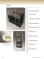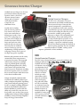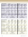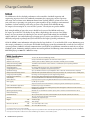
1
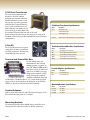
Product Guide
Powering the Planet, One System at a Time
History
Welcome
2001 OutBack Power started by a passionate group of
engineers whom wanted to bring power conversion
electronics technology into the 21st century.
This small startup quickly grew by offering innovative and
well designed solutions to renewable energy problems.
OutBack listened to their customers and made many of the
changes that were suggested, creating a truly customer focused company in the power conversion electronics industry.
2002 OutBack introduces its first sealed sinewave inverter/charger - the FX2024, with resounding success.
Welcome to the fifth year of OutBack Power designing
and manufacturing great products with you, our customers, in mind. OutBack’s ability to continuously innovate
and lead the industry as well as listen to our customers
has been a major influence in our success.
Since our last catalog, OutBack has spent countless hours
in research and development to engineer products at an
elevated level of technological innovation. Our efforts
have resulted in new products and improved reliability.
Some of these new products include: our vented higher
power versions of our inverter/chargers, the world’s most
efficient grid-interactive inverter/charger, a fully integrated
grid-interactive system and mobile inverter/chargers for
when you are on the move.
Despite our accomplishments we will not become
complacent. In 2005 we expect to maintain a steady
growth and pioneer solutions to challenging problems
and developing even more cutting edge power electronics.
We will continue to collaborate with our customers in
order to develop our products and improve our industry
leading technical support.
We are confident that OutBack is a company that is
built to last, and we would like to thank you for your
continued support in powering the planet, one system
at a time...
This single model changed the way people looked at system
design by offering unprecedented flexibility in system design
and expansion while the sealed construction allowed for uses
which previously would have been considered too “extreme”
for other inverter/chargers.
OutBack releases the MX60 solar MPPT charge controller
redefining performance and value.
This revolutionary product changed the way solar systems
were being installed and quickly gained a reputation for getting the most power possible from a PV array - often making
it more expensive to not use one.
2003 OutBack launches the first of the vented versions of
the FX series inverter/chargers.
These VFX models were introduced in direct response to our
customer’s requests providing higher power at a similar price
as the sealed counterpart.
OutBack launches the PS2 value - priced system integration
accessories.
This line of accessories addressed the needs of our customers
for competitively priced system integration accessories for
smaller systems.
2004 OutBack releases the world’s most efficient
grid-interactive inverter/charger.
These models raise the bar for performance and value for
battery-connected grid-interactive inverter/charger systems.
OutBack introduces the PS1 fully integrated grid-interactive
power system.
This unique system sets a new standard for system
integration, performance and ease of installation in
grid-interactive applications.
2005 What’s new at OutBack? Read these pages to find out...
Printed on Recycled Paper • Copyright 2005®
Index
3
Sinewave Inverter/Charger
6
Charge Controller
7
System Display and Controller
8
Communications Manager
Sinewave Inverter/Chargers
MATE
7
3
9
Remote Temperature Sensor
10
Auto Transformer
11
OutBack System Stacking
12
Grid-Interactive System
14
Design by Karen O’Bryan
System Accessories
Photography by Erik Stuhaug
Charge Controllers
2005
6
18
System Components
l
1
OutBack Power Systems Inc. 28
Off-Grid
Solar. Wind. Hydro. Generator. No matter what your energy source OutBack’s products
are engineered to provide your home or business with reliable electricity day-in and dayout. The OutBack modular system architecture allows your system to grow along with
your power needs up to 36,000 watts. Power hungry appliances like washing machines, air
conditioning and power tools are easily started by our inverter’s substantial surge power
capability. When not being used, the inverter enters a power save mode, which consumes
as little as 3 watts, saving your battery power for when you need it the most. OutBack’s
innovative Maximum Power Point Tracking (MPPT) technology gets the most from your
solar array or can also control hydro or wind turbine charging sources. Complete system
status and control is easily monitored by a single control, instead of requiring the user to
keep an eye on multiple displays and status indicators.
Grid-Interactive
Grid-Interactive renewable energy systems enable you to demonstrate your personal
commitment to a renewable energy future. With the OutBack grid-interactive system,
backup AC power is made available 24 hours a day in the event of a utility outage, providing reliable power and peace-of-mind. At night, the inverter’s automatic power save mode
ensures that energy is not wasted by needlessly charging your batteries from the utility
grid. An average conversion efficiency of 91% using the California Energy Commission
(CEC) test protocol provides greater savings and a shorter time period for system payback.
OutBack’s grid-interactive technology provides you more than a typical solar inverter, we
also have an unmatched ability to utilize solar, wind and hydropower sources.
Mobile and Marine
OutBack’s Mobile and Marine inverter/charger models provide the high performance and
reliability you need no matter where your travels take you. Our die-cast metal construction
allows mounting in any position, even upside down. The required AC input neutral/ground
switching is taken care of by a fully integrated 30 amp AC transfer switch for shore chord
or generator hook-up. Three circuit boards and a simple design make field servicing the
unit easy no matter where you are. Rigorous testing at the factory ensures that each
inverter/charger works the first time as well as for many years to come.
European and Exports
Wherever you are in the world, OutBack’s European and Export off-grid inverter/chargers
are engineered to provide your home or business with reliable 50 Hz AC power. Our
high surge power capability starts the most demanding of 230 volt appliances and
the modular system architecture makes expanding a system’s power capacity or
switching to three-phase output power simple and trouble free. Both sealed (FX) and
vented (VFX) models are available with 50 Hz output to match your installation’s environmental conditions. The inverter/chargers low weight (as low as 27 kilograms) and
compact dimensions allow easy transport and installation in less than ideal locations.
Our field serviceable design eliminates the need to ship inverters if repair or upgrades
are required. Superior technical support is available from our European office, allowing questions to be promptly answered and any problems to be quickly resolved.
l
2
28
OutBack Power Systems Inc.
2005
Sinewave Inverter/Charger
OutBack inverter/chargers are the next
generation in advanced power management. Each is a DC to AC
sinewave inverter, battery
charger and AC transfer
switch housed within
a tough die-cast
aluminum chassis.
Just like the local utility
grid, the inverter produces
true sinewave AC electricity for your stand-alone or
backup power needs. Computers, TVs and pumps are
just some of the examples of
modern electronics that last
longer and run better when
powered with true sinewave
electricity from an OutBack
inverter. Starting up your air
conditioning, washing machine or
well pump is worry-free because of
our high surge power capability.
Batteries and generators are the costly
consumables when using inverters
to generate electricity. The integrated
smart battery charger uses multiple
stages to perform quick recharging
while prolonging battery life, saving
your batteries and generator from
unnecessary wear. Automatic switching
between AC power sources is seamless
due to an AC transfer switch that reacts
in less than 16 milliseconds.
Unique networked communication
is built into all OutBack products providing complete integration. Expanding
your system with your growing power
needs is as simple as adding additional
inverters with modular architecture.
Further flexibility is provided with the
ability to be connected at any time in either parallel, series or three-phase power
configurations. Industry leading OutBack
reliability is achieved through simplified
design and rugged construction.
2005
FX
Sealed Inverter/Chargers
The FX series is designed to survive in
environments that would normally destroy
other inverter/chargers. Protection for
internal components is provided by our
die-cast aluminum chassis with a powder
coated finish to prevent corrosion. Internal
and external cooling fins allow for passive
heat transfer, enabling peak operating
efficiencies as high as 93% and looking cool
while doing it. Water and small particles
are kept out through the generous use of
gaskets and 0-ring seals on all seams and
openings. A protective conformal coating
on all circuit boards provides the final line of
defense against corrosion. The now standard
externally mounted “TURBO” cooling system
improves performance in hot conditions.
VFX
Vented Inverter/Chargers
The VFX series is designed for more protected installations. By
utilizing an efficient active cooling design, the VFX models are
available with AC output up to
3.6 kilowatts. Our tough diecast aluminum chassis
physically protects the
internal components
while the air intake
includes an easily
cleaned filter, which
allows for ventilation
while also keeping
bugs and other debris
out. All circuit boards
are conformal coated to
prevent corrosion from
airborne moisture in
humid conditions. The now
standard DC wiring cover
(DCC) protects the DC
terminals and battery cables
from damage.
l
3
OutBack Power Systems Inc. 28
Off-Grid Specifications
Sealed Models
Nominal DC Input Voltage
Continuous Power Rating at 25° C
AC Voltage/Frequency
Continuous AC RMS Output at 25° C
Idle Power
Full
Search
Typical Efficiency
Total Harmonic Distortion
Typical
Maximum
Output Voltage Regulation
Maximum Output Current
Peak
RMS
AC Overload Capability
Surge
5 Second
30 Minutes
AC Input Current Maximum
AC Input Voltage Range (MATE Adjustable)
AC Input Frequency Range
DC Input Voltage Range
Continuous Battery Charge Output
Minimum Recommended DC Breaker
Warranty
Weight
Unit
Shipping
Dimensions (H x W x L)
Unit
Shipping
12 VDC
24 VDC
48 VDC
2000 VA
2500 VA
3000 VA
120 VAC 60 Hz
120 VAC 60 Hz
120 VAC 60 Hz
17.0 amps AC
20.8 amps AC
25.0 amps AC
~ 20 Watts
~ 20 Watts
~ 23 Watts
~ 6 Watts
~ 6 Watts
~ 6 Watts
90%
92%
93%
2%
2%
2%
5%
5%
5%
± 2%
± 2%
± 2%
56 amps AC
70 amps AC
70 amps AC
40 amps AC
50 amps AC
50 amps AC
4800 VA
6000 VA
6000 VA
4000 VA
4800 VA
4800 VA
2500 VA
3200 VA
3200 VA
60 amps AC
60 amps AC
60 amps AC
80 to 150 VAC
80 to 150 VAC
80 to 150 VAC
54 to 66 Hz
54 to 66 Hz
54 to 66 Hz
10.5 to 17.5 VDC
21.0 to 34.0 VDC
42.0 to 68.0 VDC
80 amps DC
55 amps DC
35 amps DC
OBDC-250
OBDC-175
OBDC-100
Standard 2 year / Optional 5 year
62.6 lbs (28.4 kg)
67 lbs (30 kg)
13 x 8.25 x 16.25” (33 x 21 x 41 cm)
21.75 x 13 x 22” (55 x 33 x 56 cm)
FX2012T
FX2524T
FX3048T
Grid-Interactive Specifications
Sealed Models
Nominal DC Input Voltage
Continuous Power Rating at 25° C
AC Voltage/Frequency
Continuous AC RMS Output at 25° C
Idle Power
Full
Search
Typical Efficiency
Total Harmonic Distortion
Inverting
Selling
Output Voltage Regulation
Maximum Output Current
Peak
RMS
AC Overload Capability
Surge
5 Second
30 Minutes
AC Input Current Maximum
AC Input Voltage Range (MATE Adjustable)
AC Input Frequency Range
DC Input Range
Continuous Battery Charge Output
Minimum Recommended DC Breaker
Warranty
Weight
Unit
Shipping
Dimensions (H x W x L)
Unit
Shipping
24 VDC
48 VDC
2500 VA
3000 VA
120 VAC 60 Hz
120 VAC 60 Hz
20.8 amps AC
25.0 amps AC
~ 20 Watts
~ 20 Watts
~ 6 Watts
~ 6 Watts
92%
93%
2%
2%
< 5%
< 5%
± 2%
± 2%
70 amps AC
70 amps AC
50 amps AC
50 amps AC
6000 VA
6000 VA
4800 VA
4800 VA
3200 VA
3200 VA
60 amps AC
60 amps AC
80 to 150 VAC
80 to 150 VAC
58 to 62 Hz
58 to 62 Hz
21.0 to 34.0 VDC
42.0 to 68.0 VDC
55 amps DC
35 amps DC
OBDC-175
OBDC-100
Standard 2 year / Optional 5 year
62.6 lbs (28.4 kg)
67 lbs (30 kg)
13 x 8.25 x 16.25” (33 x 21 x 41 cm)
21.75 x 13 x 22” (55 x 33 x 56 cm)
l
4
28
OutBack Power Systems Inc.
GTFX2524
GTFX3048
Vented Models
VFX2812
VFX3524
VFX3648
12 VDC
24 VDC
48 VDC
2800 VA
3500 VA
3600 VA
120 VAC 60 Hz
120 VAC 60 Hz
120 VAC 60 Hz
23.3 amps AC
29.2 amps AC
30.0 amps AC
~ 20 Watts
~ 20 Watts
~ 23 Watts
~ 6 Watts
~ 6 Watts
~ 6 Watts
90%
92%
93%
2%
2%
2%
5%
5%
5%
± 2%
± 2%
± 2%
56 amps AC
70 amps AC
70 amps AC
40 amps AC
50 amps AC
50 amps AC
4800 VA
6000 VA
6000 VA
4000 VA
5000 VA
5000 VA
3200 VA
4000 VA
4000 VA
60 amps AC
60 amps AC
60 amps AC
80 to 150 VAC
80 to 150 VAC
80 to 150 VAC
54 to 66 Hz
54 to 66 Hz
54 to 66 Hz
10.5 to 17.0 VDC
21.0 to 34.0 VDC
42.0 to 68.0 VDC
125 amps DC
85 amps DC
45 amps DC
OBDC-250
OBDC-250
OBDC-175
Standard 2 year / Optional 5 year
61 lbs (27.7 kg)
64 lbs (29 kg)
12 x 8.25 x 16.25” (30 x 21 x 41 cm)
21.75 x 13 x 22" (55 x 33 x 56 cm)
Vented Models
GVFX3524
GVFX3648
24 VDC
48 VDC
3500 VA
3600 VA
120 VAC 60 Hz
120 VAC 60 Hz
29.2 amps AC
30.0 amps AC
~ 20 Watts
~ 20 Watts
~ 6 Watts
~ 6 Watts
92%
93%
2%
2%
< 5%
< 5%
± 2%
± 2%
70 amps AC
70 amps AC
50 amps AC
50 amps AC
6000 VA
6000 VA
5000 VA
5000 VA
4000 VA
4000 VA
60 amps AC
60 amps AC
80 to 150 VAC
80 to 150 VAC
58 to 62 Hz
58 to 62 Hz
21.0 to 34.0 VDC
42.0 to 68.0 VDC
85 amps DC
45 amps DC
OBDC-250
OBDC-175
Standard 2 year / Optional 5 year
61 lbs (27.7 kg)
64 lbs (29 kg)
12 x 8.25 x 16.25” (30 x 21 x 41 cm)
21.75 x 13 x 22" (55 x 33 x 56 cm)
2005
Mobile Specifications
Sealed Models
Nominal DC Input Voltage
Continuous Power Rating at 25° C
AC Voltage/Frequency
Continuous AC RMS Output at 25° C
Idle Power
Full
Search
Typical Efficiency
Total Harmonic Distortion
Typical
Maximum
Output Voltage Regulation
Maximum Output Current
Peak
RMS
AC Overload Capability
Surge
5 Second
30 Minutes
AC Input Current Maximum
AC Input Voltage Range (MATE Adjustable)
AC Input Frequency Range
DC Input Range
Continuous Battery Charge Output
Minimum Recommended DC Breaker
Warranty
Weight
Unit
Shipping
Dimensions (H x W x L)
Unit
Shipping
12 VDC
24 VDC
32 VDC
2000 VA
2500 VA
2500 VA
120 VAC 60 Hz
120 VAC 60 Hz
120 VAC 60 Hz
17.0 amps AC
20.8 amps AC
20.8 amps AC
~ 20 Watts
~ 20 Watts
~ 21 Watts
~ 6 Watts
~ 6 Watts
~ 6 Watts
90%
92%
92%
2%
2%
2%
5%
5%
5%
± 2%
± 2%
± 2%
56 amps AC
70 amps AC
56 amps AC
40 amps AC
50 amps AC
40 amps AC
4800 VA
6000 VA
4800 VA
4000 VA
4800 VA
4000 VA
2500 VA
3200 VA
2500 VA
30 amps AC
30 amps AC
30 amps AC
80 to 150 VAC
80 to 150 VAC
80 to 150 VAC
54.0 to 66.0 Hz
54.0 to 66.0 Hz
54.0 to 66.0 Hz
10.5 to 17.0 VDC
21.0 to 34.0 VDC
28.0 to 45.3 VDC
80 amps DC
55 amps DC
35 amps DC
OBDC-250
OBDC-175
OBDC-125
Standard 2 year / Optional 5 year
62.6 lbs (28.4 kg)
67 lbs (30 kg)
13 x 8.25 x 16.25” (33 x 21 x 41 cm)
21.75 x 13 x 22” (55 x 33 x 56 cm)
European Specifications
Nominal DC Input Voltage
Continuous Power Rating at 25° C
AC Voltage/Frequency
Continuous AC RMS Output at 25° C
Idle Power
Full
Search
Typical Efficiency
Total Harmonic Distortion
Typical
Maximum
Output Voltage Regulation
Maximum Output Current
Peak
RMS
AC Overload Capability
Surge
5 Second
30 Minutes
AC Input Current Maximum
AC Input Voltage Range (MATE Adjustable)
AC Input Frequency Range
DC Input Voltage Range
Continuous Battery Charge Output
Minimum Recommended DC Breaker
Warranty
Weight
Unit
Shipping
Dimensions (H x W x L)
Unit
Shipping
2005
FX2012MT
FX2012ET
FX2524MT
Sealed Models
FX2024ET
FX2532MT
FX2348ET
12 VDC
24 VDC
48 VDC
2000 VA
2000 VA
2300 VA
230 VAC 50 Hz
230 VAC 50 Hz
230 VAC 50 Hz
8.7 amps AC
8.7 amps AC
10.0 amps AC
~ 20 Watts
~ 20 Watts
~ 23 Watts
~ 6 Watts
~ 6 Watts
~ 6 Watts
90%
92%
93%
2%
2%
2%
5%
5%
5%
± 2%
± 2%
± 2%
28 amps AC
35 amps AC
35 amps AC
20 amps AC
25 amps AC
25 amps AC
4600 VA
5750 VA
5750 VA
4000 VA
4800 VA
4800 VA
2500 VA
3100 VA
3100 VA
30 amps AC
30 amps AC
30 amps AC
160 to 300 VAC
160 to 300 VAC
160 to 300 VAC
44 to 56 Hz
44 to 56 Hz
44 to 56 Hz
10.5 to 17.0 VDC
21.0 to 34.0 VDC
42.0 to 68.0 VDC
100 amps DC
55 amps DC
35 amps DC
OBDC-250
OBDC-175
OBDC-100
Standard 2 year / Optional 5 year
62.6 lbs (28.4 kg)
67 lbs (30 kg)
13 x 8.25 x 16.25” (33 x 21 x 41 cm)
21.75 x 13 x 22” (55 x 33 x 56 cm)
Vented Models
VFX2812M
VFX3524M
VFX3232M
12 VDC
24 VDC
32 VDC
2800 VA
3500 VA
3200 VA
120 VAC 60 Hz
120 VAC 60 Hz
120 VAC 60 Hz
23.3 amps AC
29.2 amps AC
26.6 amps AC
~ 20 Watts
~ 20 Watts
~ 21 Watts
~ 6 Watts
~ 6 Watts
~ 6 Watts
90%
92%
92%
2%
2%
2%
5%
5%
5%
± 2%
± 2%
± 2%
56 amps AC
70 amps AC
56 amps AC
40 amps AC
50 amps AC
40 amps AC
4800 VA
6000 VA
4800 VA
4000 VA
5000 VA
4000 VA
3200 VA
4000 VA
4000 VA
30 amps AC
30 amps AC
30 amps AC
80 to 150 VAC
80 to 150 VAC
80 to 150 VAC
54.0 to 66.0 Hz
54.0 to 66.0 Hz
54.0 to 66.0 Hz
10.5 to 17.0 VDC
21.0 to 34.0 VDC
28.0 to 45.3 VDC
125 amps DC
85 amps DC
45 amps DC
OBDC-250
OBDC-250
OBDC-175
Standard 2 year / Optional 5 year
61 lbs (27.7 kg)
64 lbs (29 kg)
12 x 8.25 x 16.25” (30 x 21 x 41 cm)
21.75 x 13 x 22" (55 x 33 x 56 cm)
VFX2612E
Vented Models
VFX3024E
VFX3048E
12 VDC
24 VDC
48 VDC
2600 VA
3000 VA
3000 VA
230 VAC 50 Hz
230 VAC 50 Hz
230 VAC 50 Hz
11.3 amps AC
13.0 amps AC
13.0 amps AC
~ 20 Watts
~ 20 Watts
~ 23 Watts
~ 6 Watts
~ 6 Watts
~ 6 Watts
90%
92%
93%
2%
2%
2%
5%
5%
5%
± 2%
± 2%
± 2%
28 amps AC
35 amps AC
35 amps AC
20 amps AC
25 amps AC
25 amps AC
4600 VA
5750 VA
5750 VA
4000 VA
4800 VA
4800 VA
3100 VA
3300 VA
3300 VA
30 amps AC
30 amps AC
30 amps AC
160 to 300 VAC
160 to 300 VAC
160 to 300 VAC
44 to 56 Hz
44 to 56 Hz
44 to 56 Hz
10.5 to 17.0 VDC
21.0 to 34.0 VDC
42.0 to 68.0 VDC
120 amps DC
85 amps DC
42 amps DC
OBDC-250
OBDC-250
OBDC175
Standard 2 year / Optional 5 year
61 lbs (27.7 kg)
64 lbs (29 kg)
12 x 8.25 x 16.25” (30 x 21 x 41 cm)
21.75 x 13 x 22" (55 x 33 x 56 cm)
l
5
OutBack Power Systems Inc. 28
Charge Controller
MX60
The MX60 raises the bar for high performance solar controllers. OutBack’s ingenuity and
engineering experience has been combined to maximize the output power of your expensive
solar array. Our real time active Maximum Power Point Tracking (MPPT) system ensures that
your solar array is operating at its peak power point regardless of age, shading or environmental
conditions. Systems with large solar arrays are now a snap thanks to the MX60’s 60 amp
DC output current rating for 12, 24 or 48 VDC systems - all with just one product model!
Real wiring flexibility of your solar array is finally here because of the MX60’s wide range
DC input, up to 150 VOC. The ability to step-down a high voltage solar array to a low voltage
battery can save you money by reducing the size of wire required and making the installation
simpler and faster. Our smart multistage recharging process ensures your batteries are recharged
efficiently and gently to prolong battery life and achieves the highest possible performance.
All of the MX60’s status information is displayed on the large built-in 3.1" (8 cm) backlit LCD screen. Monitoring your
solar array’s performance is easy because of included data logging system that automatically records the last 64 days of
system operation. OutBack’s network communication system allows your MX60 to communicate with the rest of your
OutBack system, eliminating multiple product interaction problems and allowing remote monitoring via the OutBack
MATE display up to 1000 feet / 300 meters away.
MX60 Specifications
Nominal Battery Voltage
Output Current
Maximum Solar Array Size
PV Open Circuit Voltage (VOC)
Standby Power Consumption
Charging Regulation
Voltage Regulation Set points
Equalization Voltage
Battery Temperature Compensation
Voltage Step-Down Capability
Power Conversion Efficiency
Typical
Status Display
Remote Interface
Data Logging
Hydro / Wind Turbine Applications
Positive Ground Applications
Operating Temperature Range
Environmental Rating
Conduit Knockouts
Warranty
Weight
Dimensions (H x W x L)
Unit
Shipping
Unit
Shipping
12, 24, 32, 36, 48, 54 or 60 VDC (Single model)
60 amps maximum with adjustable current limit for smaller systems
12 VDC systems 800 Watts / 24 VDC systems 1600 Watts / 48 VDC systems 3200 Watts
150 VDC absolute maximum coldest conditions / 135 VDC start-up and operating maximum
1 Watt or less
Five Stages: Bulk, Absorption, Float, Silent and Equalization
13 to 80 VDC User adjustable with password protection
Up to 5.0 VDC above Absorb Set point Adjustable Timer - Automatic Termination when completed
Automatic with optional RTS installed / 5.0 mV per °C per battery cell / 30 mV per °C for a 12 VDC system
Can charge a lower voltage battery from a higher voltage PV array
98% at 60 amps with a 48 V battery and nominal 48 V solar array
3.1” (8 cm) backlit LCD screen with 4 lines with 80 alphanumeric characters total
Proprietary network system using RJ 45 Modular Connectors with CAT 5e Cable (8 wires)
Last 64 days of operation
amp hours, watt hours and time in float for each day along with total lifetime power production
Consult factory for approved turbines
Requires two pole breakers for switching both positive and negative conductors on both solar array
and battery connections
Minimum -40° to maximum 60° C (Power capacity of the controller is derated when above 25° C)
Indoor Type 1
Two .5” (13 mm) and .75” (19 mm) on the back; One .75” (19 mm) and 1” (25 mm) on each side;
Two .75” (19 mm) and 1” (25 mm) on the bottom
Standard 2 year / Optional 5 year
11.6 lbs (5.3 kg)
14 lbs (6.4 kg)
13.5 x 5.75 x 4” (40 x 14 x 10 cm)
18 x 11 x 8” (46 x 30 x 20 cm)
Use appropriate wire size in accordance with NEC.
Note * Add 1% to the solar arrays open circuit voltage for every 2.5° C expected below the 25° C standard panel rating (STC). The resulting value must be below 150 VDC at the
lowest expected temperatures conditions and less than 135 VDC for typical conditions to ensure reliable operation.
l
6
28
OutBack Power Systems Inc.
2005
System Display and Controller
MATE
The MATE system display and controllers are complete management
tools for your OutBack Power system. Through the use of a single
MATE you can remotely manage and monitor multiple inverter/
chargers, MX60s and any future OutBack power conversion and
control products.
The MATE and MATE2 are packed full of features to make system
management simple. The easy-to-read 3.1" (8 cm) LCD is backlit for
dark operating conditions. Four soft keys allow easy context-based
navigation of menus and functions. Two hot keys give immediate
access to AC and inverter functions.
A built-in clock and calendar function enables timer based programming of inverter and charger operation. This permits you to set the
system to work with time-of-day power rates or to limit a generator’s
run time to a specific time period of the day or week. All of your settings
are stored in permanent memory to eliminate the need to reprogram in
the event of a system shutdown or battery replacement. The MATE and
MATE2 include a RS232 port with DB9 jack for connection to the serial
port of a PC computer. Through the use of optional WinVerter software
you can perform such operations as data logging and graphical display
of the system’s operation and performance.
MATE2M
The MATE2M is the same
technology as the MATE
and MATE2 but is designed
to be used with your
M-series inverter/chargers
in mobile applications.
Incorporating a more
simplified menu, the settings
needed for mobile power
system management are
more quickly accessed.
A flush mount case design
makes installation in boats
and RVs more compact
and attractive.
Communication with multiple
products requires optional HUB
2005
MATE
MATE2 and MATE2M
MATE Specifications
MATE
Surface mount with RS232
Grey
MATE2
Flush mount with RS232
Black
MATE2M
Flush mount without RS232
Black
Interface Display
3.1" (8 cm) backlit LCD
Control Keypad
6 backlit silicone keys - dedicated inverter and AC input keys
Status Indicators
Two LED Status Indicators
Communication Protocol
Proprietary OutBack Multi-drop using an OutBack HUB4 or HUB10
Interconnection Cabling
Standard CAT 5 network cable with RJ45 modular jack - 50' (5 m) included
PC Computer Interface
RS232 opto-isolated DB9 jack 9600 baud serial communication
Microprocessor
16 MHz low power consumption version
Set point and Data Memory
32K non-volatile flash RAM
Clock / Calendar
On-board real time clock with battery backup
Environmental Rating
Indoor Type 1
Maximum Cable Length
1000' (300 m)
Warranty
Standard 2 year / Optional 5 year
Weight
Shipping
1 lb (.5 kg)
Dimensions (H x W x L)
Shipping
5.75 x 4.25 x 2” (15 x 11 x 5 cm)
l
7
OutBack Power Systems Inc. 28
Communications Manager
HUB
The HUB system communications managers are the backbone of your networked
OutBack power conversion system. The
OutBack HUB communicates stacking,
load share and power save off/on signals.
Interconnection cabling is standard
Ethernet CAT5 with RJ45 modular jacks.
Through the use of a HUB, your system is
completely coordinated and managed by
the MATE.
HUB Specifications
HUB4
HUB10
Number of Ports
4 Plus MATE
10 Plus MATE
1 lb (.5 kg)
3 lbs (1.4 kg)
10.5 x 6.25 x 1.27” (27 x 16 x 3 cm)
12 x 6 x 5” (31 x 15 x 13 cm)
1 lb (.5 kg)
3 lbs (1.4 kg)
10.5 x 6.25 x 1.27” (27 x 16 x 3 cm)
12 x 6 x 5” (31 x 15 x 13 cm)
Weight
Dimensions (H x W x L)
Unit
Shipping
Unit
Shipping
HUB4
HUB4
HUB10
l
8
28
OutBack Power Systems Inc.
2005
Remote Temperature Sensor
RTS
The OutBack Remote Temperature Sensor (RTS) is a necessary tool
for proper battery charging. All OutBack products with integrated
battery charging have a temperature compensation system built-in
which benefits from the installation of the optional RTS. The RTS
ensures that your OutBack system knows the precise ambient temperature so that it can recharge your batteries safely and efficiently.
Systems with multiple OutBack products connected to one HUB4 or
HUB10 require only a single RTS to be installed.
15' (5 m) cable
Battery Charging
Batteries are a key component in backup and off-grid systems, often serving as the only energy storage device.
To guarantee that they function properly it is important that your batteries are maintained. A chief part of this
maintenance is proper charging. Your batteries should always be maintained above a 50% level of charge and receive
a complete recharge once a month to ensure operation at peak performance. Prolonged use of the battery below a
50% state of charge will adversely affect the long-term health of the battery and can result in premature failure.
The multistage charging process uses several regulation stages to allow fast recharging of the battery energy
storage system while ensuring a long battery life, high performance and efficient operation of the overall system.
The charging process begins with the BULK stage, where maximum current is sent to the batteries until the target
“absorb” voltage is reached and the absorb stage of the charge begins. During ABSORB, the charger provides the
batteries with the just enough current to hold at the set voltage for a preset amount of time. Following this cycle, the
charging system changes between available OutBack charging products. Using the MX-60, the batteries enter the
FLOAT stage where they are given a maintenance charge until there is no excess renewable energy. The FX or VFX
inverter/charger will go into SILENT mode where the charger turns off until the battery voltage drops to the
“re-float” setting. At this point the inverter/charger initiates the maintenance FLOAT charge. This method reduces
fuel and utility consumption.
It should be noted that the temperature of your batteries has an impact on the charging process. The OutBack RTS
should be used to monitor this. In higher ambient temperatures, the battery charging regulation settings will be
reduced to prevent overcharging of the batteries. Conversely, in lower ambient temperature conditions, the regulation
settings will be increased to ensure complete recharging of the batteries.
Voltage
Batteries are composed of a group of individual cells. Through normal use, the charge of each individual cell will not
be equal to the other cells. To address this, your batteries should be EQUALIZED either once each month or once
every few months depending on usage. During the equalization charge the electrolyte in the battery is stirred up by
gas bubbles, which help to create
BULK
ABSORB
SILENT
FLOAT TIME*
SILENT
FLOAT TIME*
SILENT
an equal mixture of water and
TIME *
acid. Simultaneously the full cells
are overcharged which allows the
low cells to “catch up” and all of
the active material in the battery
to be reconverted to its charged
state. Depending on usage, the
hardened battery plate material
that is no longer active in the battery-sulfation can also be reduced
Time
by an equalization charge.
* MATE Adjustable
2005
l
9
OutBack Power Systems Inc. 28
Auto Transformer
PSX-240
The OutBack PSX-240 auto transformer can be used for step-up, step-down,
generator and split phase output balancing or as a series stacked inverter to
load balancing auto-former. Incorporating a transformer with 120 volt/30
amp primary and secondary side, a temperature activated cooling fan and a
25 amp dual breaker in a steal enclosure, the PSX-240 is ready to install in
your custom application. Use for 120 or 240 VAC 60 Hz systems only.
Powering 240 volt items like deep well pumps with a single 120 volt
inverter is possible thanks to the PSX-240’s step-up capability. Its step-down feature
allows you to charge your batteries with a 240 volt generator through a single 120 volt inverter.
The PSX-240’s ability to balance the output of series stacked inverter/chargers makes it a critical item when
using the OutBack stacking 120/240 VAC configuration.
The X-240 is also available without the enclosure, for installation inside the PS2AC or PS4AC enclosures.
Step-Up
240 VAC
Loads
Inverter/Charger
PSX-240
Step-Down
120 VAC
Loads
120/240 VAC Generator
PSX-240
Inverter/Charger
Generator Balancing
120/240 VAC
Loads
120/240 VAC Generator
PSX-240
Inverter/Charger
OutBack Balancing
120/240 VAC
Loads
120/240 VAC Generator
l
10 OutBack Power Systems Inc.
28
Inverter/Charger
PSX-240
2005
Stacking
At OutBack, we adhere to a philosophy that a power system should be fully customizable to address your specific
needs. Therefore we set out to create the world’s only group of inverter/chargers that use a truly modular architecture.
This modular architecture uses the next generation of a technique referred to as “stacking” to enable you to tailor your
system for higher output power, increased charging capabilities and/or three-phase power configuration.
Whether stacked in parallel, classic series, series/parallel or three-phase there is always an inverter/charger which
performs the task of Master. The Master talks to the other units through the HUB system communications manager
while performing three major roles, keeping all inverter/chargers properly phased, controlling inverter and charger
output levels, as well as putting unused inverters into Power Save mode to improve efficiency at low AC load levels.
Parallel Stacking - More power at same output voltage
When the inverter/chargers are stacked in parallel all inverter and charger outputs are combined. This means that each inverters AC output
is added up to equal your total system AC output, up to 36,000 watts, in phase at the same 120 VAC/60 Hz or 230 VAC/50 Hz output voltage.
Charging output amperage is also combined in this same manner.
Load
3 kW 120 VAC
3 kW 120 VAC
9 kW
120 VAC
3 kW 120 VAC
Classic Series Stacking - More power at higher output voltage
Stacking inverter/chargers in classic series provides a system with split phase 120/240VAC. This method does not allow balancing between
separate legs on a system and is can only be used in dual inverter/charger systems without the X-240 Auto Transformer.
Load
3 kW 120 VAC
3 kW 120 VAC
3 kW
120 VAC
Leg 1
3 kW
120 VAC
Leg 2
or
6 kW
240 VAC
Leg 1
and
Leg 2
OutBack Series/Parallel Stacking - More power at all output voltages
Series/Parallel stacking or OutBack (OB) stacking is unique to OutBack inverter/chargers. Never before has it been possible to have inverter/chargers balancing loads intelligently between two legs of AC power while seamlessly changing between series and parallel. OB Stacking uses the X-240
auto transformer to balance the loads between the two separate series legs of a system. The X-240 allows AC loads on leg 1 and leg 2 to be powered
by any combination of inverter/chargers within your system. Even if there are only two inverter/chargers, connected in series, they can also function as if connected in parallel. This allows larger AC loads to be operated by a system without risking overloading one of the 120 VAC outputs.
Load
3 kW 120 VAC
3 kW 120 VAC
9 kW
120 VAC
Leg 1
3 kW 120 VAC
X-240
3 kW 120 VAC
9 kW
120 VAC
Leg 2
or
12 kW
240 VAC
Leg 1
and
Leg 2
3-Phase Stacking - More power for three-phase loads
Three inverter/chargers can be configured to provide 120/208 VAC or 230/400VAC four wire “Wye/Star” three-phase AC Power. An inverter/
charger is used to power each of the three legs for 3-phase AC power. The loads on each of the inverters does not need to be kept balanced,
each phase is independently voltage regulated.
Load
3 kW 120 VAC
3 kW 120 VAC
3 kW 120 VAC
2005
3 kW
120 VAC
3 kW
120 VAC
or
9 kW
208 VAC
3-Phase
3 kW
120 VAC
l
11
OutBack Power Systems Inc. 28
Grid-Interactive System
PS1
The PS1 is advanced engineering and refinement that
you have come to expect from OutBack Power in a next
generation grid-interactive solar electric system. The system’s
battery backup is a silent and hands-off alternative to noisy
and maintenance intensive generators.
In side-by-side “real world” testing the PS1 system
performs within 5% of the industry leading battery-less
grid-tie inverter, translating into more savings when using
net metering. The same field proven MPPT technology found
in the MX60 solar charge controller is featured in the PS1.
This cutting edge concept gives the system the ability to use
your PV array at its peak output. Uninterrupted AC power is
provided by the PS1’s system’s true sinewave inverter that has
an industry leading, California Energy Commission (CEC)
certified, efficiency of 91%, thus guaranteeing that your
household appliances run seamlessly while utilizing all
available solar power. Your recommended AGM batteries
are maintained and charged by an innovative OutBack
multistage charging process, a valuable feature that assists in
providing reliable backup power and a battery life up to 10
years. An ultra-fast 16 millisecond transfer switch guarantees
that even sensitive backup loads, such as computers, never
know when a grid outage occurs.
Like every OutBack Power product, the PS1 is rugged. All
components are protected within an aluminum type 3R
rainproof enclosure. The ETL listed system is pre-wired by
OutBack engineers to ensure that the PS1 system works reliably
for years to come. A standard 5 year warranty provides peace of
mind and satisfies state rebate requirements.
PS1 Specifications
Model
PS1 - 3000
PS1 - 2500
PS1 - BE
Description
Vented Inverter/Charger with MX60 and HUB4
Sealed Inverter/Charger with MX60 and HUB4
Battery Enclosure with all cables (Order batteries separately)
PS1 Options
Model
OBAC-20
OBAC-15
Rating
25 amp 120 VAC
15 amp 120 VAC
Version
Single Pole OutBack
Single Pole OutBack
Width
.05” (13 mm)
.05” (13 mm)
Model
OBPV-8
OBPV-10
OBPV-15
Rating
8 amps 125 VDC
10 amps 125 VDC
15 amps 125 VDC
Version
Single Pole OutBack
Single Pole OutBack
Single Pole OutBack
Width
.05” (13 mm)
.05” (13 mm)
.05” (13 mm)
l
12 OutBack Power Systems Inc.
28
2005
PS1 Specifications
Continuous Power Rating
AC Voltage / Frequency Output
AC Input Current Maximum
Maximum AC Surge Current
At 40° C
At 25° C
AC Transfer Switch
Battery Charger
Peak (1 millisecond)
RMS (5 seconds)
Maximum PV Array Wattage
PV Open Circuit Voltage
MPPT Input Voltage Range
PV Array Ground Fault Protection
Inverter Efficiency
MPPT Efficiency
Overall System Efficiency
Battery Voltage - Nominal
Minimum / maximum operating range
Battery Charge Rate
AC Output Voltage Regulation
AC Output Current
Total Harmonic Distortion
AC Transfer Switch Speed
Battery Temperature Sensor
Operating Temperature Range
Recommended Minimum Energy Storage
Recommended Batteries
Communications
Enclosure Materials
Mounting
Recommended Mounting Hardware
System Enclosure Dimensions (H x W x D)
Battery Enclosure Dimensions (H x W x D)
System Weight
Battery Enclosure Weight (without batteries)
Certifications
Anti-Islanding Measures
Warranty
Field Installed Options
2005
Maximum
Typical
Peak
Typical
Peak
Inverter
MX60
Typical
Nominal
Inverting
Selling
Inverting
Selling
Typical
Unit
Shipping
Unit
Shipping
Unit
Shipping
Unit
Shipping
Sealed Models
Vented Models
PS1-2500
PS1-3000
2500 VA
3000 VA
120 VAC 60 Hz
50 amps AC
16 amps AC with automatic back-off
70 amps AC
50 amps AC
3300 watts DC stc rating
150 VDC
44 to 135 VDC
Standard - 80 amp DC
91% (not CEC Certified)
93%
98%
89%
92%
48 VDC
40 to 60 VDC
35 amps DC
60 amps DC
5%
120 VAC
25.0 amps AC
20.8 amps AC
2% VAC THD
< 5% current THD per UL1741 conditions
< 16 Milliseconds
Included
-40° C to 60° C (power derated above 25° C)
4 kWHRS at 80% discharge
Four AGM type 31 or type 27 sealed VRLA
Optional MATE system display with RS232 port
Powder coated aluminum, stainless steel hardware
Wall mount, 16 on center studs
5/16 x 2.5” Lag Bolts - three per side minimum
31.3 x 17.25 x 12.9” (80 x 44 x 33 cm)
3000 VA
3600 VA
120 VAC 60 Hz
50 amps AC
20 amps AC with automatic back-off
70 amps AC
50 amps AC
3300 watts DC stc rating
150 VDC
44 to 135 VDC
Standard - 80 amp DC
91% (CEC Certified)
93%
98%
89%
92%
48 VDC
40 to 60 VDC
45 amps DC
60 amps DC
5%
120 VAC
30.0 amps AC
25.0 amps AC
2% VAC THD
< 5% current THD per UL1741 conditions
< 16 Milliseconds
Included
-40° C to 60° C (power derated above 25° C)
4 kWHRS at 80% discharge
Four AGM type 31 or type 27 sealed VRLA
Optional MATE system display with RS232 port
Powder coated aluminum, stainless steel hardware
Wall mount, 16" on center studs
5/16 x 2.5” Lag Bolts - three per side minimum
31.3 x 17.25 x 12.9” (80 x 44 x 33 cm)
40.5 x 20.5 x 17.25” (103 x 52 x 44 cm)
36.25 x 17.25 x 12.55” (92 x 44 x 32 cm)
43.25 x 20.25 x 16.75” (110 x 51 x 43 cm)
107 lbs (49 kg)
117 lbs (53 kg)
29 lbs (13 kg)
47 lbs (21 kg)
ETL certified to the UL1741 standard
UL1741 compliant
5 year limited repair warranty standard
MATE or MATE2 remote system display
OBAC breakers for additional AC load circuits
OBPV breakers for PV array series string protection
l
OutBack Power Systems Inc. 13
28
System Accessories
PS2
OutBack Power offers compact enclosures for all of the
AC and DC components of a renewable energy power
conversion system. The PS2 series saves time, money
and space by combining the disconnects, over-current
protection devices and control components into easyto-install enclosures. Capable of supporting one or two OutBack FX series inverter/chargers, up to three MX60 charge
controllers, a MATE system controller and all the associated AC and DC components.
The OutBack PS2 series can be fully customized to your application and ordered pre-wired or as individual
components for field assembly.
PS2AC Breaker Panel
The PS2AC is engineered to be a code-compliant steel enclosure for AC power
routing and management.
•
•
•
•
•
•
•
•
ETL listed indoor type powder coated enclosure
Ground terminal bus bar bonded to cabinet
One white insulated AC neutral terminal bus bar
Two black insulated bus bars for Hot AC IN and OUT Leg 1
Two red insulated bus bars for Hot AC IN and OUT Leg 2
Knockouts for eight additional OutBack AC load breakers
Provisions for mounting an X-240 and cooling fan
Knockouts on five surfaces to facilitate conduit and inverter connections
Shown with 120/240 VAC/60 Hz dual inverter bypass (50D) or 230 VAC/50 Hz dual
inverter bypass (50DE) and additional AC load breakers
PS2DC Breaker Panel
The PS2DC is a code-compliant steel enclosure engineered to contain all DC power
routing and management components.
•
•
•
•
•
•
•
•
ETL listed indoor type powder coated enclosure with plenty of conduit knockouts
Knockouts for one additional inverter battery breaker and eight 3/4" (19 mm)
breakers
500 amp 50 mVolts DC current shunt standard
Battery negative/ground bus bar standard
Battery positive bus bar for DC loads and PV arrays included standard
Knockouts for battery conduit, MX60 interconnect and stacking another PS2DC
Use for negative or positive ground systems
Knockouts on five surfaces to facilitate conduit - inverter connections and
additional MX60s
Shown with DC breakers and DC-GFP/2 - order separately
l
14 OutBack Power Systems Inc.
28
2005
PS2AC and PS2DC Breaker Panel Specifications
Model
PS2AC-50D
PS2AC-50DE
PS2AC
Standard Breakers
50 amp 120/240 VAC 60 Hz Bypass assembly
50 amp 120/230 VAC 50 Hz Bypass assembly
No breakers included
Dimensions Unit (H x W x D)
18.5 x 11.5 x 9” (47 x 29 x 23 cm)
18.5 x 11.5 x 9” (47 x 29 x 23 cm)
18.5 x 11.5 x 9” (47 x 29 x 23 cm)
Dimensions Shipping (H x W x D)
22 x 15 x 12” (56 x 38 x 30 cm)
22 x 15 x 12” (56 x 38 x 30 cm)
22 x 15 x 12” (56 x 38 x 30 cm)
Weight Unit
22 lbs (10 kg)
22 lbs (10 kg)
20 lbs (9 kg)
PS2DC-175
PS2DC-250
PS2DC
175 amp DC Breaker
250 amp DC Breaker
No Breakers included
18.5 x 11.5 x 9” (47 x 29 x 23 cm)
18.5 x 11.5 x 9” (47 x 29 x 23 cm)
18.5 x 11.5 x 9” (47 x 29 x 23 cm)
22 x 15 x 12” (56 x 38 x 30 cm)
22 x 15 x 12” (56 x 38 x 30 cm)
22 x 15 x 12” (56 x 38 x 30 cm)
22 lbs (10 kg)
22 lbs (10 kg)
20 lbs (9 kg)
OutBack PS2AC Bypass Assemblies Specifications - for field installations in bare PS2AC version
Model
Inverter Output
Bypass Breaker Rating
Input Breaker Rating
PS2-IOB-50D
120/240 VAC 60 Hz
50 amps at 120/240 VAC
50 amps at 120/240 VAC
Output Breaker Rating
50 amps at 120/240 VAC
PS2-IOB-50DE
230 VAC 50 Hz
50 amps at 230 VAC
50 amps at 230 VAC
50 amps at 230 VAC
PS2 DC Breaker Configurations
1M
1S
2S
3S
4S
5S
6S
7S
2M
3M
8S
1L
2L
The PS2DC Breaker Panel has eight small
.75" (19 mm), three medium 1" (26 mm) or
two large 1.5" (32 mm) breaker positions. The
small sizes are 1-80 amps, medium sizes are
100 or 125 amps an the large sizes are 175 or
250 amps.
PS2 Mounting Plate
The PS2MP is a steel powder coated,
one-part mounting plate for all your
PS2 series accessories and up to two
OutBack Inverter/Chargers.
20"
(51 cm)
44" (112 cm)
PS2 Mounting Plate Specifications
Model
Dimensions Unit (H x W x D)
Dimensions Shipping (H x W x D)
Weight Shipping
PS2MP
20 x 44 x .75” (51 x 112 x 2 cm)
22.25 x 49.5 x 3” (56 x 126 x 8 cm)
24 lbs (10.8 kg)
2005
l
OutBack Power Systems Inc. 15
28
System Accessories
PS4
The PS4 series is the ideal AC and DC enclosure system for medium to large
size renewable energy power conversion system. The PS4 is comprised of two
compact enclosures for all of your system’s AC and DC components. It saves
time, money and space by combining disconnects, over-current protection
devices and control components into easy-to-install enclosures.
The PS4 is capable of supporting up to four OutBack FX series inverter/chargers, six MX60 charge controllers, a MATE
system controller and all the required AC and DC components and wiring.
The OutBack PS4 system can be fully customized to your application and ordered pre-wired or as individual
components for field assembly.
PS4AC Breaker Panel
The PS4AC is a NEC compliant enclosure engineered to contain all the AC overcurrent protection
and power management components.
•
•
•
•
•
•
•
•
•
•
•
•
•
ETL listed indoor type powder coated steel enclosure with plenty of knockout and mounting
provisions for a variety of OutBack products.
Available without the AC bypass assembly included (PS4AC) (Order all required AC breakers separately)
Available with a four FX inverter ready 60 amp 120/240VAC AC bypass assembly (PS4-IOB-60Q) for
systems with AC generators or utility grid connections up to 15 kW
Available with a four FX inverter ready 100 amp 120/240VAC AC bypass assembly (PS4-IOB-100Q)
for systems with large AC generators or grid connections over 15kW
Available with a four FX inverter ready 60 amp 230VAC 50 Hz AC bypass assembly (PS4-IOB-60QE)
for export applications
Ground terminal bus bar bonded to cabinet
One white insulated AC neutral terminal bus bar
Two black insulated AC hot/leg 1 terminal bus bars
Two red insulated AC hot/leg 2 terminal bus bars
Complete wiring kit is included when the AC bypass kit is included or ordered separately
Space provided for up to 13 additional OutBack AC load breakers
Provisions for mounting an X-240 autotransformer and optional cooling fan
Knockouts on five surfaces to facilitate conduit and inverter connections
PS4DC Breaker Panel
The PS4DC is a NEC compliant enclosure engineered to contain all the DC overcurrent
protection and power management components.
•
•
•
•
•
•
•
•
•
•
l
ETL listed indoor type powder coated steel enclosure with plenty of knockout and mounting
provisions for a variety of OutBack products.
Available without any DC breakers included (PS4DC) (Order all required DC breakers separately)
Also available with one inverter/battery DC breaker included standard (PS4DC-175 amp
or PS4DC-250)
Space provided for up to four large breakers (175 or 250 amp) or six medium breaker (100 or
125 amps) - can also be combined as two large and three medium breakers
Space provided for an additional ten small breakers (1 to 80 amps 150 VDC rated) as well as
the OutBack PV-GFP/2 ground fault protection system
500 amp 50 mVolts DC current shunt standard
One combined negative/ground bus bar attached to the DC shunt included standard
One positive terminal bus bar (TBB-R) for DC loads or PV array combining included standard
Can be used for negative or positive ground systems
Knockouts on five surfaces to facilitate conduit and inverter connections
16 OutBack Power Systems Inc.
28
2005
PS4 Breaker Panel Specifications
Model
PS4AC-60Q
PS4AC-100Q
PS4AC-60QE
PS4AC
Standard Breakers
60 amp 120/240VAC 60 Hz Bypass assembly
100 amp 120/240VAC 60 Hz Bypass assembly
60 amp 230VAC 50 Hz Bypass assembly
No bypass included
Dimensions Unit (H x W x D)
18.26 x 11.45 x 8.8” (46 x 29 x 22 cm)
18.26 x 11.45 x 8.8” (46 x 29 x 22 cm)
18.26 x 11.45 x 8.8” (46 x 29 x 22 cm)
18.26 x 11.45 x 8.8” (46 x 29 x 22 cm)
Dimensions Shipping (H x W x D)
12 x 14 x 21” (31 x 36 x 53 cm)
12 x 14 x 21” (31 x 36 x 53 cm)
12 x 14 x 21” (31 x 36 x 53 cm)
12 x 14 x 21” (31 x 36 x 53 cm)
Weight Shipping
26 lbs (12 kg)
26 lbs (12 kg)
26 lbs (12 kg)
24 lbs (11 kg)
PS4DC-175
PS4DC-250
PS4DC
One 175 amp DC breaker
One 250 amp DC breaker
No breakers included
18.26 x 11.45 x 8.8” (46 x 29 x 22 cm)
18.26 x 11.45 x 8.8” (46 x 29 x 22 cm)
18.26 x 11.45 x 8.8” (46 x 29 x 22 cm)
12 x 14 x 21” (31 x 36 x 53 cm)
12 x 14 x 21” (31 x 36 x 53 cm)
12 x 14 x 21” (31 x 36 x 53 cm)
24 lbs (11 kg)
24 lbs (11 kg)
22 lbs (10 kg)
OutBack PS4AC Bypass Assemblies Specifications - for field installations in bare PS4AC version
Model
Inverter Output
Bypass Breaker
Input Breaker
Output Breaker
PS4-IOB-60Q
120/240 VAC 60 Hz
60 amps at 120/240 VAC
Four 50 amps at 120 VAC
Four 50 amps at 120 VAC
PS4-IOB-100Q
120/240 VAC 60 Hz
100 amps at 120/240 VAC
Four 50 amps at 120 VAC
Four 50 amps at 120 VAC
PS4-IOB-60QE
230 VAC 50 Hz
60 amps at 230 VAC
Four 30 amps at 230 VAC
Four 30 amps at 120/230 VAC
PS4DC Breaker Configurations
1M
1S
2S
3S
4S
5S
6S
7S
8S
2M
3M
4M
5M
6M
9S 10S
1L
2L
3L
4L
The PS4DC Breaker Panel has ten small .75" (19 mm), up to six medium 1" (26 mm) or four large 1.5" (32 mm)
breaker positions. The small sizes are 1-80 amps, medium sizes are 100 or 125 amps an the large sizes are 175
or 250.
PS4 Mounting Plate
The PS4MP is a steel powder coated, one-part
mounting plate for all your PS4 series accessories and up to four OutBack Inverter/Chargers.
25.5"
65 (cm)
38.3" (97 cm)
PS4 Mounting Plate Specifications
Model
PS4MP
2005
Dimensions Unit (H x W xD)
25.5 x 38.3 x 3” (65 x 97 x 8 cm)
Dimensions Shipping (H x W x D)
36 x 50 x 1” (91 x 127 x 3 cm)
Weight Shipping
46 lbs (21 kg)
l
OutBack Power Systems Inc. 17
28
System Components
OutBack AC Breakers
Hydraulic-Magnetic type breakers that are DIN
rail “snap-in” mountable and can be used for input, output or load circuits. 1/2" (13 mm) wide.
OutBack AC Breaker Specifications
Model
OutBack DC Breakers
Panel mounted Hydralic-Magnetic type breakers
which can be used for DC sources, inverters or
load circuits. 3/4" (18 mm) wide.
Rating
Version
Width
OBAC-50
120VAC
Single Pole
0.5” (13 mm)
OBAC-50D
120/240VAC
Dual Pole
1.0” (26 mm)
OBAC-50-3P
120/208VAC
Three Pole
1.5” (39 mm)
OBAC-50DE
240VAC
Dual Pole
1.0” (26 mm)
OBAC-30
120VAC
Single Pole
0.5” (13 mm)
OBAC-30D
120/240VAC
Dual Pole
1.0” (26 mm)
OBAC-25D
120/240VAC
Dual Pole
1.0” (26 mm)
OBAC-20
120VAC
Single Pole
0.5” (13 mm)
OBAC-20D
120/240VAC
Dual Pole
1.0” (26 mm)
OBAC-15
120VAC
Single Pole
0.5” (13 mm)
OBAC-15D
120/240VAC
Dual Pole
1.0” (26 mm)
OutBack DC Breaker Specifications
OutBack PV Ground Fault
Protection System
The OBDC-GFP/2 is required by the NEC for
PV arrays mounted on residential dwelling
roofs. It can be used with the PS2DC, PS4DC or
PS1. An OBDC-GFP/2 protects wiring and system components for one or two PV arrays: dual
80 amp PV circuits 150 VDC max VOC. The
OBDC-GFP/2 system includes the GFP unit, a
ground bus bar, neutral and ground connection
wiring and mounting hardware.
l
18 OutBack Power Systems Inc.
28
Model
Current Rating
Stud Terminal Size
Width
OBDC-250
250 amp 125 VDC
3/8 “ stud
1.5" (39 mm)
OBDC-175
175 amp 125 VDC
3/8” stud
1.5" (39 mm)
OBDC-125
125 amp 125 VDC
5/16" stud
1.0” (26 mm)
OBDC-100
100 amp 125 VDC
5/16” stud
1.0” (26 mm)
OBDC-80
80 amp 150 VDC
5/16” stud
0.75" (19 mm)
OBDC-70
70 amp 150 VDC
1/4” stud
0.75" (19 mm)
OBDC-60
60 amp 150 VDC
1/4” stud
0.75" (19 mm)
OBDC-50
50 amp 150 VDC
1/4” stud
0.75" (19 mm)
OBDC-40
40 amp 150 VDC
1/4” stud
0.75" (19 mm)
OBDC-30
30 amp 150 VDC
1/4” stud
0.75" (19 mm)
OBDC-20
20 amp 150 VDC
1/4” stud
0.75" (19 mm)
OBDC-15
15 amp 150 VDC
1/4” stud
0.75" (19 mm)
OBDC-10
10 amp 150 VDC
1/4” stud
0.75" (19 mm)
OBDC-5
5 amp 150 VDC
1/4” stud
0.75" (19 mm)
OBDC-1
1 amp 150 VDC
1/4” stud
0.75" (19 mm)
OutBack PV Ground Fault Protection Specifications
Model
Description
Stud Terminal Size
OBDC-GFP/2
80 amp at 150 VDC
2 Poles - Requires 3
2005
X-240 Auto Transformer
The same auto transformer and
breakers as the PSX-240 but
designed to be housed within the
PS2AC or PS4AC. It can be used
for step-up, step-down, generator
and split phase output balancing
or as a series stacked inverter-toload balancing auto-former. It can
also transfer up to 2kW (3kW with
the optional X fan kit) from one side of the total
power rating of the generator or the total power rating of an
OutBack stacked series/parallel 120/240 VAC inverter/charger
configuration.
X-Fan Kit
The X-Fan Kit increases the power
rating of the X-240 to a maximum
of 6 kVA continuous. Thermostatic
controlled 120 VAC powered.
Terminal and Ground Bus Bars
Use for adding more wire
terminations or for isolating
multiple positive / negative circuits. All TBB and GBB models
have three #1/0 to 14 AWG and
eight #6 to 14 AWG screw type
compression terminals, which
means no ring lugs required.
Available with black, white and
red insulators. The Battery Bus is .25" (7 mm) thick tin plated
copper and can be mounted on the back plate of the PS2DC /
PS4DC or directly on the battery breaker terminals.
Conduit Adapters
Allows connection of the FX and VFX inverter/chargers to the
PS2 and PS4 breaker panels or 2" conduit.
X-240 Auto Transformer Specifications
Model
X-240
Description
120/240 VAC 60 Hz
2.0 kW without Fan Kit
3.0 kW with X-Fan Kit
X-Fan Kit
Thermostatic controlled brushless fan 120 VAC Powered
Terminal and Ground Bus Bars Specifications
Model
Description
GBB
Ground Bus Bar not insulated
TBB
Terminal Bus Bar with black insulators
TBB-B
Terminal Bus Bar with blue insulators
TBB-R
Terminal Bus Bar with red insulators
TBB-W
Terminal Bus Bar with white insulators
Conduit Adapters Specifications
Model
Description
ACA
FX and VFX AC end
DCA
FX and VFX DC end
Mounting Brackets Specifications
Model
Description
PS2-CCB
One MX60
PS2-CCB2
Two MX60s
PS4-CCB2
Two MX60s
Mounting Brackets
The mounting bracket allows MX60 charge controllers to be
mounted on the side of the PS2DC or PS4DC enclosures.
2005
l
OutBack Power Systems Inc. 19
28
System Components
PV Array Combiner Box
The PSPV is a solar array combiner which can be used with a wide variety
of system configurations and solar module types. The PSPV is designed to
provide NEC code compliant series over current protection of the wiring
of multiple PV modules or subarrays for connection to charge controllers,
inverters or other systems components. The rainproof aluminum enclosure
is easily field configured to match your PV system design and amperage
requirements.
• Rainproof, outdoor Type 3R powder coated aluminum enclosure
• Approved for installation on both vertical and angled surfaces with a slope as little as 3-in-12 pitch - also can
be pole mounted (Brackets not included)
• Designed for use with up to twelve OutBack’s OBPV breakers for PV array configurations of 12 to 72 VDC
systems - maximum open circuit voltage of 150 VDC
• Also can use the OutBack OBFH “touch safe” type fuse holders for high voltage systems - maximum open
circuit voltage of 600 VDC
• Includes dual combining bus bars which can be installed to provide one or two separate PV output circuits
from a single PSPV enclosure
• Includes one terminal bus bar (TBB) and has mounting holes for an additional TBB
• Includes two #1/0 AWG set-screw compression type box lug terminals for output wiring
• Includes one #1/0 AWG ground lug which can be mounted either on the inside or outside surface of
the enclosure
• Two 1 inch side knockouts which can be
punched out to allow for larger 1.25"
(3 cm) conduit
• Eight .5" (13 mm) knockouts on bottom for PV
module or subarray input wiring
• Clearance is provided on bottom and back main
knockouts to allow up to a 2" (5 cm) conduit
punch for larger cabling
• For negative or positive ground PV systems
• Enclosure ships without breakers or fuse holders
(Order separately)
Photo courtesy of Bob-O Schultz, Electron Connection
l
20 OutBack Power Systems Inc.
28
2005
Photovoltaic (PV)
Array Breakers
PV breakers are Hydraulic-Magnetic type and are not affected by
high ambient temperatures. All breakers have a 10 year warranty.
Maximum of twelve OBPV in one PSPV enclosure.
PV Array Fuses
and Fuse Holders
DIN rail snap-in mount with #8 AWG setscrew type compression
terminals. Touch-safe design. Not rated for load make or load
break usage. UL listed for up to 600 VDC. Maximum of eight
fuse holders in one PSPV enclosure.
Terminal and Ground Bus Bars
Use for adding more wire terminations or for isolating multiple
positive / negative circuits. Has three #1/0 to 14 AWG and eight
#6 to 14 AWG screw type compression terminals, which means
no ring lugs required.
2005
PV Array Breakers Specifications
Model
Rating
OBPV-2
2 amps 150 VDC
OBPV-4
4 amps 150 VDC
OBPV-6
6 amps 150 VDC
OBPV-8
8 amps 150 VDC
OBPV-9
9 amps 150 VDC
OBPV-10
10 amps 150 VDC
OBPV-15
15 amps 150 VDC
OBPV-30
30 amps 150 VDC
PV Array Fuses Specifications
Model
Description
OBFH
Fuse Holder only
OBF-6
6 amp 600 VDC
OBF-10
10 amp 600 VDC
OBF-15
15 amp 600 VDC
Terminal and
Ground Bus Bars Specifications
Model
Description
TBB
Terminal Bus bar with black insulators
GBB
Ground terminal Bus bar
l
OutBack Power Systems Inc. 21
28
Main Office
19009 62nd Avenue NE
Arlington, WA 98223 USA
Phone: (360) 435.6030
Fax: (360) 435.6019
European Office
Urb. Garraf II, Buzón 214
C/. Eramprunya #26
08860 - Les Botígues de Sitges
Barcelona, ESPAÑA
Phone: (+34) 600.843.845
www.outbackpower.com