1
OutBack Power Systems
“Americas” and “Mobile”
FX and VFX Inverter/Charger
Installation and Programming Manual
Document Revision 7.2
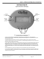
FX 2012T - 2.0 kW / 12 VDC / 120 VAC / 60 Hz (Sealed + Turbo / Americas)
FX 2524T - 2.0 kW / 24 VDC / 120 VAC / 60 Hz (Sealed + Turbo / Americas)
FX 3048T - 2.5 kW / 48 VDC / 120 VAC / 60 Hz (Sealed + Turbo / Americas)
VFX 2812 - 2.8 kW / 12 VDC / 120 VAC / 60 Hz (Ventilated / Americas)
VFX 3524 - 3.5 kW / 24 VDC / 120 VAC / 60 Hz (Ventilated / Americas)
VFX 3648 - 3.6 kW / 48 VDC / 120 VAC / 60 Hz (Ventilated / Americas)
FX 2012MT - 2.0 kW / 12 VDC / 120 VAC / 60 Hz (Sealed + Turbo / Mobile)
FX 2524MT - 2.0 kW / 24 VDC / 120 VAC / 60 Hz (Sealed + Turbo / Mobile)
FX 2532MT - 2.5 kW / 32 VDC / 120 VAC / 60 Hz (Sealed + Turbo / Mobile)
VFX 2812M - 2.8 kW / 12 VDC / 120 VAC / 60 Hz (Ventilated / Mobile)
VFX 3524M - 3.5 kW / 24 VDC / 120 VAC / 60 Hz (Ventilated / Mobile)
VFX 3232M - 3.2 kW / 32 VDC / 120 VAC / 60 Hz (Ventilated / Mobile)
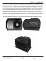
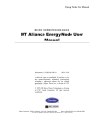
“T” stands for Turbo
“M” stands for Mobile
The “Sealed” version of the FX
The “Vented” version of the FX
The “Turbo Kit” that comes with the FX “T” series is shown on page 15
Please check our website at www.outbackpower.com for the latest product information
Installation & Programming Manual
FX & VFX Series Inverter/Charger System
900-0027-1
Page 1
Rev 7.2
08/26/05
Copyright 2003 OutBack Power Systems, Inc.
19009 62nd Ave NE, Arlington WA 98223 USA
Tel 360 435 6030
Fax 360 435 6019
Installation & Programming Manual
FX & VFX Series Inverter/Charger System
900-0027-1
Page 2
Rev 7.2
08/26/05
Copyright 2003 OutBack Power Systems, Inc.
19009 62nd Ave NE, Arlington WA 98223 USA
Tel 360 435 6030
Fax 360 435 6019
TABLE OF CONTENTS
IMPORTANT SAFETY INSTRUCTIONS ........................................................................................... 5
Installation Guidelines ....................................................................................................................... 5
General Precautions ........................................................................................................................... 6
Additional Notices .............................................................................................................................. 6
Personal Precautions While Working with Batteries...................................................................... 6
RATINGS.................................................................................................................................................. 7
MOUNTING ............................................................................................................................................. 9
COMPLETE OUTBACK INTEGRATED SYSTEMS ...................................................................... 10
AC WIRING CONNECTIONS............................................................................................................. 11
INDICATORS & CONTROL WIRING .............................................................................................. 12
DC BATTERY TERMINALS ................................................................................................................................ 13
EQUIPMENT GROUND TERMINALS............................................................................................................... 13
BATTERY TERMINAL COVERS ....................................................................................................................... 13
FX ACCESSORIES................................................................................................................................ 14
TURBO KIT INFORMATION............................................................................................................. 15
HUB COMMUNICATION MANAGER ............................................................................................. 16
FX SYSTEM CONFIGURATIONS ..................................................................................................... 17
Single FX System .............................................................................................................................. 17
Series or Series/Parallel Dual FX System....................................................................................... 18
Paralleled Dual FX System .............................................................................................................. 19
Series/Parallel Quad FX System ..................................................................................................... 20
Paralleled Quad FX System............................................................................................................. 21
3-Phase FX System ........................................................................................................................... 22
START-UP & OPERATION................................................................................................................. 23
BATTERY CHARGING INFORMATION......................................................................................... 24
BATTERY CHARGING SETPOINTS ................................................................................................................. 24
BATTERY EQUALIZATION................................................................................................................................ 24
RTS – THE REMOTE TEMPERATURE SENSOR............................................................................................ 24
BATTERY CHARGING SEQUENCE.................................................................................................................. 24
BATTERY CHARGING CONSTRAINTS........................................................................................................... 25
STACKING INFORMATION .............................................................................................................. 26
Classic, OutBack, and 3-Phase Stacking Methods ........................................................................ 26
X-240 AUTOTRANSFORMER CAPACITY ....................................................................................................... 26
STACKING INSTRUCTIONS ............................................................................................................. 27
Stacking Procedure .......................................................................................................................... 27
STACK PHASE ....................................................................................................................................................... 27
POWER SAVE LEVEL MASTER ADJUST ONLY ............................................................................................ 28
Copyright 2003 OutBack Power Systems, Inc.
19009 62nd Ave NE, Arlington WA 98223 USA
Tel 360 435 6030
Fax 360 435 6019
FX & VFX Series Inverter/Charger System
Installation & Programming Manual
900-0027-1
Rev 7.2
08/26/05
Page 3
POWER SAVE LEVEL SLAVE ADJUST ONLY................................................................................................ 28
System Examples .............................................................................................................................. 28
DUAL-STACKED SYSTEM USING “CLASSIC” STACKING ........................................................................ 28
STACKED SYSTEM USING OUTBACK’S “PARALLEL” STACKING........................................................ 28
STACKED SYSTEM USING OUTBACK’S “SERIES / PARALLEL” STACKING ...................................... 29
3-PHASE STACKED SYSTEM (3 FX’s ONLY).................................................................................................. 30
AUTOMATIC GENERATOR START INSTRUCTIONS ................................................................ 31
MOBILE FX INFORMATION ............................................................................................................ 32
General .............................................................................................................................................. 32
GROUND SWITCHING......................................................................................................................................... 32
STACKING MOBILE FX INVERTER/CHARGERS......................................................................................... 32
MAXIMUM AC INPUT CURRENT ..................................................................................................................... 32
Dual Input Transfer Switch Setup.................................................................................................. 33
MATE - SYSTEM CONTROLLER AND DISPLAY......................................................................... 34
Inverter Control ............................................................................................................................... 38
AC Input Control ............................................................................................................................. 39
MATE - MENU MAP ............................................................................................................................ 40
MATE SCREENS .................................................................................................................................. 42
Summary Screen .............................................................................................................................. 42
EXAMPLES ............................................................................................................................................................. 42
Status Screens ................................................................................................................................... 43
MODES MENU ....................................................................................................................................................... 43
METER MENU ....................................................................................................................................................... 44
BATTERY MENU................................................................................................................................................... 45
ERROR MENU........................................................................................................................................................ 46
WARNING MENU.................................................................................................................................................. 47
DISCONNECT MENU ........................................................................................................................................... 48
SELL MENU............................................................................................................................................................ 49
Setup Screens .................................................................................................................................... 50
SEARCH MENU ..................................................................................................................................................... 50
INPUT MENU.......................................................................................................................................................... 51
Advanced Screens............................................................................................................................. 52
INVERTER MENU ................................................................................................................................................. 53
CHARGER MENU.................................................................................................................................................. 54
GRID MENU............................................................................................................................................................ 55
GENERATOR MENU ............................................................................................................................................ 56
AUXILIARY MENU ............................................................................................................................................... 57
STACKING MENU................................................................................................................................................. 59
SELL MENU............................................................................................................................................................ 60
CALIBRATION MENU ......................................................................................................................................... 61
WIRE SIZES .......................................................................................................................................... 62
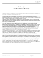
WARRANTY .......................................................................................................................................... 63
REGISTRATION................................................................................................................................... 65
Extended Warranty Application..................................................................................................... 65
Installation & Programming Manual
FX & VFX Series Inverter/Charger System
900-0027-1
Page 4
Rev 7.2
08/26/05
Copyright 2003 OutBack Power Systems, Inc.
19009 62nd Ave NE, Arlington WA 98223 USA
Tel 360 435 6030
Fax 360 435 6019
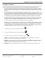
IMPORTANT SAFETY INSTRUCTIONS
Installation Guidelines
This manual contains important instructions for the OutBack FX series inverter/charger system with the software which allows classic
(two FX’s in series), parallel and series/parallel stacking of two to ten FX’s for higher power and/or higher voltage systems.
1
All of the AC wiring to the AC terminals is to be torqued to 30 inch-pounds (equivalent to 2.5 foot-pounds or 3.4 Nm).
Wiring to these terminals must meet requirements of the National Electric Code (NEC). The terminals will accept up to 6AWG.
Use copper conductors only with insulation rated for 75˚ C. See the AC WIRING CONNECTIONS section of this manual for more
information.
2
Torque the DC connections to 60 inch-pounds (equivalent to 5 foot-pounds or 6.8 Nm). Cables to these terminals must use
a crimp on type ring terminal or compression type lug. Cable must meet the requirements of the National Electrical Code. Use
of large gauge cables (2/0 or 4/0 AWG) or larger is advisable to reduce losses and ensure high performance of the FX. Cables of
too small a gauge can result in poor performance and even damage the FX. Keep the cables together as much as possible and
ensure that both cables pass through the same knockout and conduit fittings and to allow the inductive currents to cancel.
3
For equipment grounding hook up, see the system configuration sections in this manual. Non-mobile (“M”) FXs are intended to
be installed as part of a permanently grounded electrical system per the NEC. Mobile FXs include integral “Ground-switching”
mechanisms. Please refer to the MOBILE FX INFORMATION section of this manual for proper grounding instructions.
4
AC overcurrent protection for all connections must be provided by others as part of the installation.
5
DC battery circuit overcurrent protection must be provided by others as part of the installation. OutBack offers 100, 175 and 250
amp DC breakers (part number OBDC-XXX) which can be used with the FX. For “Mobile” installations, OutBack includes a stud
mounted fuse which can be connected directly to the positive DC terminal of the FX – it is available in 100, 175 and 250 amp
sizes (part number SMF-XXX). The stud mounted fuses require a 10mm hole in the battery terminal lug. US lugs are typically
3/8” diameter. Light filing may be required to insure proper fit of the nut shoulder into the lug hole.
6
The equipment ground on the inverter is marked with this symbol:
7
This inverter has a single phase output. It is marked with this symbol:
8
This inverter puts out a sine wave waveform. It is marked with this symbol:
9
CAUTION: To reduce the risk of fire, connect only to a circuit provided with 60 amp maximum branch-circuit overcurrent
protection in accordance with the National Electrical Code, ANSI/NFPA 70.
10
WARNING: To reduce the risk of fire, do not connect a single FX to both hot legs of a 120/240 VAC AC load center having multi
wire (common neutral) branch circuits connected. Use two FX’s wired in a series configuration or the addition of an X-240
autotransformer if you are connecting to a 120/240 VAC multi wire system.
11
IMPORTANT: Always install the battery terminal covers, even in systems that include the DCC (DC Compartment Cover).
Copyright 2003 OutBack Power Systems, Inc.
19009 62nd Ave NE, Arlington WA 98223 USA
Tel 360 435 6030
Fax 360 435 6019
FX & VFX Series Inverter/Charger System
Installation & Programming Manual
900-0027-1
Rev 7.2
08/26/05
Page 5
IMPORTANT SAFETY INSTRUCTIONS
General Precautions
1.
2.
3.
4.
5.
6.
7.
Before using the FX, read all instructions and cautionary markings on (1) the FX, (2) the batteries and (3) all appropriate sections
of this installation and operation manual.
CAUTION - To reduce risk of injury, charge only deep-cycle lead acid, lead antimony, lead calcium, gel cell or absorbed glass mat
type rechargeable batteries. Other types of batteries may burst, causing personal injury and damage.
The FX is approved for indoor mounting only and can be mounted in any position.
Do not disassemble the FX. Refer servicing to a qualified service center when service or repair is required. Incorrect re-assembly
may result in a risk of electric shock or fire.
To reduce risk of electric shock, disconnect all wiring before attempting any maintenance or cleaning. Turning off the FX may not
reduce this risk. Solar modules may produce hazardous voltages when exposed to light - cover them with opaque material before
servicing any connected equipment.
WARNING - WORKING IN THE VICINITY OF A LEAD ACID BATTERY IS DANGEROUS. BATTERIES GENERATE
EXPLOSIVE GASES DURING NORMAL OPERATION. Provide ventilation to outdoors from the battery compartment. The
battery enclosure should be designed to prevent accumulation and concentration of hydrogen gas in “pockets” at the top of the
enclosure. Vent the battery compartment from the highest point. A sloped lid can also be used to direct the flow of hydrogen to
the vent opening at the highest possible location.
NEVER charge a frozen battery.
8.
No terminals or lugs are required for hook-up of the AC wiring. AC wiring must be copper wire and rated for 75°C or higher.
Battery cables must be rated for 75°C or higher. Crimped and sealed copper ring terminal lugs with a 5/16” hole should be used
to connect the battery cables to the DC terminals of this FX. If using the stud mounted fuse, the positive lug must have a hole of
at least 10mm. Soldered cable lugs are also acceptable.
9. Torque all AC wiring connections to 30 inch-pounds (equivalent to 2.5 foot-pounds or 3.4 Nm).
10. Torque the DC connections to 60 inch-pounds (equivalent to 5 foot-pounds or 6.8 Nm).
11. Be careful with tools to reduce the risk of dropping metal objects onto batteries. It may short-circuit the batteries or other electrical
parts resulting in fire or explosion.
Additional Notices
1.
2.
3.
4.
For instructions on mounting, see the MOUNTING section of this manual.
For battery installation and maintenance: read the battery manufacturer's instructions prior to installation and operation.
All installations must comply with local and national electrical codes and standards.
GROUNDING INSTRUCTIONS – The FX should be connected to a grounded, permanent wiring system. For all installations, the
negative battery conductor should be bonded to the grounding system at one (and only one) point in the system. All installations
should comply with national and local codes and ordinances. Do not positive ground the FX !
Personal Precautions While Working with Batteries
1.
2.
3.
4.
5.
6.
7.
8.
9.
Someone should be within range of your voice to come to your aid.
Have plenty of fresh water and soap nearby in case battery acid contacts skin, clothing, or eyes.
Wear complete eye protection. Avoid touching eyes while working near batteries. Wash your hands with soap and warm water
when done.
If battery acid contacts skin or clothing, wash immediately with soap and water. If acid enters eye, immediately flood eye with
running cool water for at least 15 minutes and get medical attention immediately.
Baking soda neutralizes lead acid battery electrolyte. Keep a supply on hand in the area of the batteries.
NEVER smoke or allow a spark or flame in vicinity of a battery or generator.
Be extra cautious to reduce the risk of dropping a metal tool onto batteries. It could short-circuit the batteries or other electrical
parts that may result in fire or explosion.
Remove personal metal items such as rings, bracelets, necklaces, and watches when working with a battery. A battery can
produce a short circuit current high enough to weld a ring or the like to metal, causing severe burns.
If a remote or automatic generator start system is used, disable the automatic starting circuit and/or disconnect the generator from
its starting battery while servicing it to prevent starting while servicing.
Installation & Programming Manual
FX & VFX Series Inverter/Charger System
900-0027-1
Page 6
Rev 7.2
08/26/05
Copyright 2003 OutBack Power Systems, Inc.
19009 62nd Ave NE, Arlington WA 98223 USA
Tel 360 435 6030
Fax 360 435 6019
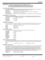
RATINGS
ATTENTION: All “FX” inverter/chargers are ETL listed to UL 1741.
All “Mobile” FX inverter/chargers are ETL listed to UL 458.
ETL is a Nationally Recognized Testing Laboratory (NRTL).
NOMINAL SYSTEM AC VOLTAGE:
This is the AC output voltage produced by an FX system. Each FX produces 120 VAC but multiple FXs can be configured in
parallel, series or 3-phase to produce different voltages between their AC output connections.
Single Phase
120 VAC at 60 Hz (VAC = volts AC, Hz = hertz)
Series Stacked
120 VAC at 60 Hz per AC output leg / 240VAC at 60Hz between the AC output legs
Parallel Stacked
120 VAC at 60 Hz on one AC output leg
Three Phase Stacked
120 VAC at 60 Hz per AC output leg / 208 VAC at 60 Hz between AC output legs (Y-connected)
RECOMMENDED DC VOLTAGE RANGE:
This is the DC battery voltage range to be used for operating the FX. The last two digits in the model number designate the
nominal DC voltage. Example: FX2024MT – 24V DC Voltage. The recommended battery voltage range is as follows.
12V Systems
11 – 16 VDC (VDC = volts DC)
24V Systems
22 – 32 VDC
32V Systems
29 – 43 VDC
48V Systems
44 – 64 VDC
MAXIMUM DC INPUT CURRENT:
This is the maximum DC current that the FX will draw from the battery when starting very large AC loads. It is not used for
sizing the DC disconnect or selecting DC cable gauge. It is used to select the minimum reasonable battery capacity.
12V FXs
600 ADC per FX (ADC = amps DC)
24V FXs
300 ADC per FX
32V FXs
225 ADC per FX
48V FXs
150 ADC per FX
RATED DC INPUT CURRENT:
This is the maximum continuous DC current that the FX will draw from the batteries when inverting.
FX2012(M)T
190 ADC (ADC = amps DC)
FX2524(M)T
120 ADC
FX2532(M)T
90 ADC
FX3048T
70 ADC
VFX2812(M)
265 ADC
VFX3524(M)
170 ADC
VFX3232(M)
115 ADC
VFX3648
85 ADC
AC INPUT OPERATING VOLTAGE RANGE:
This is the recommended AC input voltage range to be supplied to the FX. Voltages outside of this range may damage AC
loads connected to the FXs AC output terminals. This is only a recommendation, neither the FX’s defaults nor the set point
limits.
All FXs
90 – 150 VAC (VAC = volts AC)
Defaults = 108 – 140 VAC
MAXIMUM AC INPUT CURRENT:
An AC input source connected to the FX supplies power for two separate internal AC circuits – the AC transfer switch and the
battery charger. The AC transfer switch transfers the AC input power through the FX to the AC loads connected to the AC
output of the FX. The FX’s battery charger will “back off” when the combined amperage of the AC loads and the battery
charger exceeds the “AC Input Limit” (default of 28 AAC for Mobile FXs, 48 AAC for non-Moblie FXs). This “AC Input Limit”
can be adjusted so as not to overload a generator or trip a breaker that is connected to the AC input of the FX. If your
generator cannot continuously produce the “AC Input Limit” or you are connecting to an AC input source that has a breaker
that is rated for less than the “AC Input Limit”, please refer to the ADVANCED section to change this setting.
All “Mobile” FXs
30 AAC per FX (AAC = amps AC)
All Other FXs
60 AAC per FX (AAC = amps AC)
Copyright 2003 OutBack Power Systems, Inc.
19009 62nd Ave NE, Arlington WA 98223 USA
Tel 360 435 6030
Fax 360 435 6019
FX & VFX Series Inverter/Charger System
Installation & Programming Manual
900-0027-1
Rev 7.2
08/26/05
Page 7
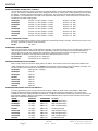
RATINGS
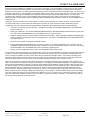
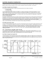
MAXIMUM CURRENT FOR BATTERY CHARGER:
The FX uses AC current from the AC input source to charge the battery. Due to heat constraints, the FX limits this amount of
current. The maximum and default values for this setting are shown below. Please refer to the programming section to adjust
this setting. The battery charger has an efficiency of about 90%. There are other factors like cable losses that may reduce
this efficiency. The maximum DC current that can be produced is also shown below. These maximum DC currents can only
be attained in the “Bulk” charging stage.
FX2012(M)T
AC Max = 12 AAC (Default = 10 AAC)
DC Max = 100 ADC
FX2524(M)T
AC Max = 14 AAC (Default = 12 AAC)
DC Max = 55 ADC
FX2532(M)T
AC Max = 14 AAC (Default = 12 AAC)
DC Max = 40 ADC
FX3048T
AC Max = 14 AAC (Default = 12 AAC)
DC Max = 35 ADC
VFX2812(M)
AC Max = 16 AAC (Default = 14 AAC)
DC Max = 125 ADC
VFX3524(M)
AC Max = 20 AAC (Default = 18 AAC)
DC Max = 85 ADC
VFX3232(M)
AC Max = 20 AAC (Default = 18 AAC)
DC Max = 60 ADC
VFX3648
AC Max = 20 AAC (Default = 18 AAC)
DC Max = 45 ADC
AC INPUT FREQUENCY RANGE:
This is the AC input source’s frequency range of which the FX will accept and stay connected. If the AC input source is out of
this range, the FX will not connect or stay connected.
All FXs
56 - 64 Hz
MAXIMUM AC OUTPUT CURRENT:
This is the amount of AC “Surge” current that the FX will supply. This amount of surge can only be supplies for a split second.
After this split second the FX lowers this surge limit. Depending on the size of the surge, the FX can be overloaded for a
minimum time of 5 seconds to a maximum time of 30 minutes. When passing an AC source through the FX via the AC
transfer switch, the maximum AC output fault current will be determined by the AC source.
All 12 VDC FXs
40 AAC per FX for 1 millisecond
All Other FXs
50 AAC per FX for 1 millisecond
MAXIMUM CONTINUOUS OUTPUT POWER:
Each FX has a maximum continuous output power it can deliver. This maximum continuous output power is hidden in the
model number of the FX. For instance, an FX2012MT has a maximum continuous output power of 2000VA (volt-amps). The
last two numbers (12 in this case) can be changed to 0’s because they refer to the battery voltage.
FX2012(M)T
2000 VA (VA = volt-amps)
FX2524(M)T
2500 VA
FX2532(M)T
2500 VA
FX3048T
3000 VA
VFX2812(M)
2800 VA
VFX3524(M)
3500 VA
VFX3232(M)
3200 VA
VFX3648
3600 VA
MAXIMUM OVERCURRENT PROTECTION AMPACITY:
This rating specifies the proper overcurrent protection ampacity. OBDC are panel mount circuit breakers. SMF are DC
terminal mounted fuses and should always be used in conjuncture with a disconnect mechanism. FX’s used in home
installations should use properly sized DC circuit breakers. An OBDC circuit breaker includes both overcurrent protection and
disconnection capability. SMFs are used primarily for marine installations where only DC overcurrent protection is required.
SMFs are included with all “Mobile” FXs.
MODEL
AMPACITY
DC BREAKER DC FUSE
FX2012(M)T
250 amps
OBDC-250
SMF-250 (Mobile Only)
FX2524(M)T
175 amps
OBDC-175
SMF-175 (Mobile Only)
FX2532(M)T
175 amps
OBDC-175
SMF-175 (Mobile Only)
FX3048T
100 amps
OBDC-100
Not Recommended
VFX2812(M)
250 amps
OBDC-250
SMF-250 (Mobile Only)
VFX3524(M)
250 amps
OBDC-250
SMF-250 (Mobile Only)
VFX3232(M)
175 amps
OBDC-175
SMF-175 (Mobile Only)
VFX3648
175 amps
OBDC-175
Not Recommended
Installation & Programming Manual
FX & VFX Series Inverter/Charger System
900-0027-1
Page 8
Rev 7.2
08/26/05
Copyright 2003 OutBack Power Systems, Inc.
19009 62nd Ave NE, Arlington WA 98223 USA
Tel 360 435 6030
Fax 360 435 6019
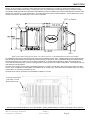
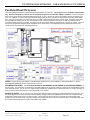
MOUNTING
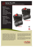
All FX’s can be mounted in any position. Better performance will be achieved if it is mounted in a location which allows for air to
circulate around the exterior of the casting. Locating the FX in a cool location will ensure the highest efficiency and power capacity.
The following drawings provide the mounting and overall dimensions of the FX with the DCC, ACA and DCA attached. All VFXs come
with the DCC and all FX “T”s come with the Turbo. The ACA and the DCA must be ordered separately. The first dimension is inches
and the second value in parenthesis is the metric value in millimeters.
DCC (or Turbo)
ACA
DCA
Depth out from Wall / Height up from Shelf: 11.87 inches (301 mm) / 12.87 INCHES (327mm) with Turbo installed
For installations where the FX may be exposed to water spray a sealed FX must be used. A sealed FX that may be exposed to water
spray should be mounted either with the base down (shelf mounting) or with the AC wiring compartment facing down (wall mounting).
This will minimize the entry of water into the AC wiring compartment. If mounted with the base down, water cannot be allowed to
accumulate around the FX’s base. There is a drainage system on the base of the FX to dispel condensation. If submerged, water can
enter this drain and cause failure.
The ACA can be used to connect the FX to the PS2AC, PS4AC or 2” conduit. The side of the ACA can be used to add an AC outlet
and one or two of OutBack’s AC rated OBDC circuit breakers (up to 70 amps max). When these items are added to the FX, it should
only be used in an area that is protected from rain.
The DCA can be used to connect the FX to the PS2DC, PS4DC or 2” conduit.
AC Wiring Compartment
(with Outlet or Circuit
Breaker Knock-Outs)
Side view of FX with FXA kit attached. The Turbo Kit adds 1” (25mm) additional height to achieve a total height of 12.87” (327mm)
Copyright 2003 OutBack Power Systems, Inc.
19009 62nd Ave NE, Arlington WA 98223 USA
Tel 360 435 6030
Fax 360 435 6019
FX & VFX Series Inverter/Charger System
Installation & Programming Manual
900-0027-1
Rev 7.2
08/26/05
Page 9
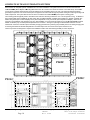
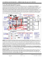
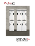
COMPLETE OUTBACK INTEGRATED SYSTEMS
Shown below are complete systems of OutBack FX’s for indoor installations. The system with four FX’s is shown mounted to the
OutBack PS4MP (Power System 4 Mounting Plate where the “4” in refers to the maximum number of FX’s that will fit). The PS4MP
comes with six 1x20mm thread forming screws for attaching FX’s and breaker boxes. The use of an external toothed star washer
(provided) is required on one screw on each piece of equipment in order to bite through the powder coating and ensure grounding of all
metal components. The system with two FX’s is shown mounted to the smaller PS2MP power system mounting plate.
The mounting plate will typically need to be bolted to the studs in a wall using at least four 1/4” or 5/16” lag bolts 2” long. In addition to
the mounting plate, these installations are also shown with an OutBack PS4DC or PS2DC (DC breaker box), PS4AC or PS2AC (AC
breaker box), DCAs (DC Conduit Adapter), DCCs (DC Compartment Cover), and ACAs (AC Compartment Adapter). When two or
more FX’s are installed in close proximity such as in this installation, it may be useful to install one or more DC-12 Fan Kits inside the
PS4DC or PS2DC (only one will fit) that will pressurize this enclosure – forcing air up through the DC Manifold and down over the
external fins of the FXs. This will improve the battery charging performance by reducing the possibility of the FX’s limiting charging due
to reaching their maximum allowed temperatures. The AUX output of the FX can be used to power the DC-12 Fan.
These components are designed to complete the installation to NEC code while offering flexibility for future expansion.
PS4AC
PS4DC
PS2DC
PS2AC
Installation & Programming Manual
FX & VFX Series Inverter/Charger System
900-0027-1
Page 10
Rev 7.2
08/26/05
Copyright 2003 OutBack Power Systems, Inc.
19009 62nd Ave NE, Arlington WA 98223 USA
Tel 360 435 6030
Fax 360 435 6019
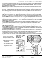
AC WIRING CONNECTIONS
The FX system and the other OutBack balance of system components are designed to make it easy to meet both local and National
Electrical Codes (NEC) installation requirements. If you are not familiar with the NEC, you should have the equipment installed by a
qualified renewable energy equipment electrician. Contact your dealer for information on qualified electricians. All wiring methods are
to be made in accordance with the National Electrical Code, ANSI/NFPA 70.
The FX includes an AC wiring compartment with both a removable cover and AC conduit plate. Depending on the type of installation,
the AC conduit plate may or may not be used.
MATE/HUB Jack
AC Terminal Block
“STATUS” LED’s
BATTERY TEMP Jack
“BATTERY” LED’s
Control Wiring
Terminal Block
Reads
“NEU/GROUND BOND”
on “Mobile” FXs
The AC terminal block is designed to accept up to 6 AWG (13.3mm2) wires. A typical installation will use THHN type wire. 6 AWG
(13.3mm2) wire is required in order to handle the 60 amp capacity of the non-Mobile FX’s AC transfer switch. 10 AWG (5.3 mm2) wire
or larger is required in order to handle the 30 amp capacity of the Mobile FX’s AC transfer switch. All AC wiring connected to the AC
terminal block must be rated for at least 75˚ C. Torque all of the set screws on the AC terminal block to 30 inch-pounds (equivalent to
2.5 foot-pounds or 3.4 Nm).
For a non-Mobile FX the AC hot input and hot output conductors should be supplied through 60 amp maximum AC branch rated circuit
breakers. The AC hot input conductor should be connected to the AC HOT IN terminal and the AC HOT OUT terminal, respectively.
The AC neutral input and AC neutral output conductors may be connected to the AC NEUTRAL IN and AC NEUTRAL OUT terminals or
a common Neutral bus. The AC NEUTRAL OUT terminal is common with the AC NEUTRAL IN terminal within the non-Mobile FX and
only one AC neutral connection is required to be connected to the FX if a separate AC neutral bus is installed. The ground wires of the
AC input and the AC output may be connected to the two CHASSIS GROUND terminals or a common Ground bus. The two CHASSIS
GROUND terminals are common within the non-Mobile FX so only one of them needs to be connected if a common Ground bus is
installed in the system.
For a Mobile FX the AC hot input and hot output conductors should be supplied through 30 amp maximum AC branch rated circuit
breakers. The AC hot input conductor should be connected to the AC HOT IN terminal and the AC HOT OUT terminal, respectively.
The AC neutral input conductor must be connected to the Mobile FX’s AC NEUTRAL IN terminal. The AC neutral output conductor
must be connected to the Mobile FX’s AC NEUTRAL OUT terminal. These two neutral terminals are not always connected within the
Mobile FX and are necessary for the proper functioning and protection of the Mobile FX’s ground-switching system. Connect the
ground conductors of the AC input and AC output to the CHASSIS GROUND terminal of the Mobile FX. If there is only one Mobile FX
in the system, leave the copper bus (provided) installed between the CHASSIS GROUND and NEU/GROUND BOND terminals. If
there is more than one Mobile FX in the system, remove the copper bus from every SLAVE FX.
Many installations will use the AC-IOB input/output bypass breaker assembly mounted in the PS2AC or PS4AC. This bypass assembly
allows the user to completely bypass the FX system for servicing or replacement. In “Normal” mode, the FXs AC hot outputs are
connected through the AC-IOB’s output breakers to the load bank. In “Bypass” mode, the AC source (generator or grid) is connected
through the AC-IOB’s bypass breakers to the load bank. In addition to the AC-IOB input/output bypass assembly, each FX has a
separate AC input breaker. When in “Bypass” mode these AC input breakers should be turned off to ensure no AC power is connected
to the FXs. After the FX has been powered down through the DC breaker, it can then be removed for servicing or replacement without
loss of AC power to the AC loads of the system.
NOTE: Non-Mobile FXs need only bypass the AC input hot conductors. Mobile FXs need to bypass both the AC input hot and AC input
neutral conductors.
Copyright 2003 OutBack Power Systems, Inc.
19009 62nd Ave NE, Arlington WA 98223 USA
Tel 360 435 6030
Fax 360 435 6019
FX & VFX Series Inverter/Charger System
Installation & Programming Manual
900-0027-1
Rev 7.2
08/26/05
Page 11
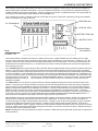
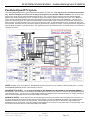
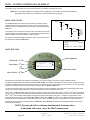
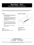
INDICATORS & CONTROL WIRING
The AC wiring compartment also encloses the following items; a 6-port terminal block, an RJ-11 jack, an RJ-45 jack, a set of three
“Battery” LEDs and a set of three “Status” LEDs. The 6-port terminal block contains ports for Inverter & On/Off, AUX + & AUX –, and
XCT + & XCT -. The RJ-11 “Battery Temp” jack accepts only OutBack’s “RTS” battery temperature sensor. Non-OutBack sensors may
fit, but if their thermister value is not identical to the RTS’s, your battery bank could be destroyed. The RJ-45 “MATE/HUB” jack accepts
the CAT-5 cable that is included with the MATE and the HUB. The “Battery” LEDs give a quick indication of the battery voltage. The
“Status” LEDs give a quick indication of whether the FX is inverting, has AC input power, or if an Error has occurred.
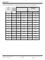
The “Battery” LEDs operate at the following voltage levels:
Nominal Battery Voltage
LED Color
12 VDC
24 VDC
Green
12.5 or higher
25.0 or higher
Yellow
11.5 to 12.5
23.0 to 25.0
Red
11.5 or lower
23.0 or lower
48 VDC
50.0 or higher
46.0 to 50.0
46.0 or lower
The “Status” LEDs operate under the following conditions:
LED Color
LED Action
LED Indicates
Green
Solid GREEN
Inverter ON
Flashing GREEN
Search Mode or Slave Power Save Mode
Off
Inverter OFF
Yellow
Solid YELLOW
AC Source is connected
Flashing YELLOW
AC Input Live – Waiting to connect to the FX
Off
No AC Input Present
Red
Solid RED
Error – An Error Message will be automatically displayed on the MATE
Flashing RED
Warning – A non-critical fault happened to the FX. The MATE can access this info.
INVERTER ON/OFF
The left two terminals of the 6-port terminal block marked INVERTER and ON/OFF can be used to control the inverter’s output.
Connecting the two terminals through a switch will allow control of the inverter output if a MATE is not available. A small jumper wire is
pre-installed into these two ports of the terminal block and must be removed in order to add the external switch. If the FX’s AC output is
off, check that the jumper wire is present and well connected. An installed switch overrides the control provided by the OutBack MATE.
If the switch is set to OFF, the MATE will not be able to turn ON the inverter. The switch cannot put the FX into Search mode.
AUXILIARY OUTPUT (AUX + / AUX -)
The Auxiliary output system uses the AUX + and AUX – terminals and is able to be programmed through the MATE to do a variety of
tasks. The default use for these terminals is to drive one 12-volt fan for external cooling. The power available at these terminals is 12
VDC at 1.0 amps (12 watts) maximum. These terminals should not be connected to any type of DC load which has a high inrush
current requirement. The FX includes internal electronic overcurrent protection for this 12 VDC output circuit which auto resets if it is
short circuited. No additional fuses are required. Use the OutBack FX Turbo Kit or DC12-FAN for cooling. For automatic or advanced
generator start functions, the Auxiliary Output can drive a 12V automotive relay for the 2-wire starting circuitry of a generator. OutBack
Power Systems does not support 3-wire start generators; however, a 3-wire to 2-wire conversion kit is available from other sources.
XCT + / XCT These terminals are not operational at this time.
BATTERY TEMP {REMOTE TEMPERATURE SENSOR (RTS)}
The OutBack FX has a 4 conductor “phone” RJ-11 modular jack located in the AC compartment for the connection of an optional
external battery temperature sensor, the RTS (sold separately), that allows for automatic adjustment of the battery charging process
based on the temperature of the battery. Battery manufacturers provide recommended charge voltages based on temperatures of 25˚C
/ 77˚F. With the RTS attached, the FX adjusts the battery voltage 0.03 volts per degree Celsius for every 12-volts of battery present.
When a HUB is used, the RTS must be plugged into the Master FX which must be plugged into port 1 of the HUB. If this is the case,
only one RTS is required for all devices plugged into the HUB. The RTS should be stuck to the side of a battery below the electrolyte
level so it can measure the temperature of the batteries. The wire from the RTS can be folded and routed underneath the transparent
gray plastic lexan cover of the AC wiring compartment to allow connection to the battery. There is a small indentation in the aluminum
casting between the battery terminals to allow for the wire to pass without affecting the sealing of the covers. When running additional
wires under the smoked lexan cover, it may be required to snip some lexan away to allow for wire routing. The lexan will not crack
when cutting or filing. IMPORTANT: Do not connect a different brand of battery temp sensor. It may cause battery failure!!!
MATE / HUB
The 8 conductor “Ethernet” RJ-45 modular jack allows direct connection of a MATE system controller and display to the FX using
standard CAT-5 type cabling. If multiple FX’s or a FX and a MX charge controller are both in the system, an OutBack HUB
communication manager is connected to this RJ-45 jack for stacking of the FX’s and for efficient system performance. The HUB acts
similarly to a computer hub to combine the communication signals of the devices together into a networked system. OutBack offers two
different HUB products at this time. The HUB-4 accepts up to four OutBack products and one MATE. The HUB-10 connects up to ten
OutBack products and one MATE. NOTE: Although the HUB has 2 ports for MATEs, only the 1st port is operational.
Installation & Programming Manual
FX & VFX Series Inverter/Charger System
900-0027-1
Page 12
Rev 7.2
08/26/05
Copyright 2003 OutBack Power Systems, Inc.
19009 62nd Ave NE, Arlington WA 98223 USA
Tel 360 435 6030
Fax 360 435 6019
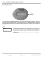
BATTERY - FX CABLING
DC BATTERY TERMINALS
The DC terminals are made from solid brass with a stainless steel threaded stud. The threads are M8 x 1.25. The black terminal is
negative and the red terminal is positive. DO NOT PUT ANY WASHERS BETWEEN THE TERMINAL MOUNTING SURFACE AND
THE ACTUAL BATTERY CABLE LUG. Place the lug, washers and nut in the following order: Lug, Flat Washer, Lock Washer, Nut.
TORQUE TO 60 INCH-POUNDS (5 FOOT POUNDS) MAXIMUM (6.77 NM). Mobile FXs come with a fuse for protection of the battery
cables connected to the FX. If used, the fuse must be mounted to the positive terminal (red). The hole of the battery cable lugs must
be at least 10mm to properly fit the fuse. If using a 3/8” hole, file this down to produce a 10mm hole. Place the lug, fuse and fuse nut
on the terminal in the following order: Fuse, Lug, Fuse Nut. TORQUE THE FUSE NUT TO 60 INCH-POUNDS (5 FOOT POUNDS)
MAXIMUM (6.77 NM). Too much torque on the fuse nut will cause the fuse nut to shatter! This will put your installation on hold. It is
recommended that a separate means of disconnecting the positive battery cable be included in systems that use fuses.
UL listed DC rated circuit breakers are available from OutBack Power Systems with amperages of 100, 175 and 250 amps DC. All of
the OutBack DC breakers come with threaded studs out the back for connection to ring type terminal lugs. ALWAYS INSTALL
BREAKERS OR FUSES WITHIN THE POSITIVE BATTERY CABLE.
OutBack also offers stud mounted fuses (SMF) for non-NEC code installations in 100, 175, and 250 amp sizes. These are the same
fuses included with the Mobile FX.
The minimum recommended cable size varies with the DC voltage. VFX2812, VFX2812M, FX2012T, FX2012MT, VFX3524 and
VFX3524M installations must use 4/0 AWG (120mm2) cable minimum. VFX3648, FX2524T, FX2524MT, and FX3048T installations
can use 2/0 AWG (70mm2) cable as long as the distances are short (less than 10 feet / 3 meters per cable). If longer distances are
required, increase the cable size to the next size as a minimum. Keep the cables together as much as possible for their entire length.
Tying or taping the cables together is also advisable.
EQUIPMENT GROUND TERMINALS
A set-screw type box lug is provided near the DC terminals to allow the connection of an equipment grounding conductor for the metal
chassis of the inverter. It is located behind the battery negative terminal on the top of the inverter casting. A green ground symbol
marks the location. When mounting an FX to a PS2MP or PS4MP, a star washer located under one of the four screws that connect the
FXs chassis to the mounting plate provides grounding of the FX to the mounting plate. Connection to the ground terminal is not required
if the star washer is used to connect the FX to the mounting plate and the mounting plate is grounded.
BATTERY TERMINAL COVERS
The battery terminal covers simply snap on. They are a little brittle, so use some care. Use a flat bladed screw driver blade in the slots
provided on the sides of the cover to pry the cap off. If the installation is exposed, DC conduit may be required. Connection of 2-inch
conduit is possible when the DCA option is added to the FX. Always install the Battery Terminal Covers, even in systems that have
an DCC or a Turbo included.
Battery Terminal Covers
Copyright 2003 OutBack Power Systems, Inc.
19009 62nd Ave NE, Arlington WA 98223 USA
Tel 360 435 6030
Fax 360 435 6019
FX & VFX Series Inverter/Charger System
Installation & Programming Manual
900-0027-1
Rev 7.2
08/26/05
Page 13
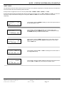
FX ACCESSORIES
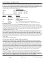
ACA (AC CONDUIT ADAPTER)
This plastic box slips into grooves on the AC end of the FX. This adapter extends
the AC wiring compartment to match the PS4AC or PS2AC. It also provides more
room for wiring than is available when using the supplied AC conduit plate.
There is a 2-inch TSC cut-out on the plastic box to allow it to be used with the
PS4AC or PS2AC disconnect enclosure or 2-inch conduit.
The ACA may also be used for mounting two breakers OBDC breakers (rated for
AC) and/or an AC outlet through the knockouts provided.
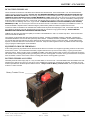
DCA (DC CONDUIT ADAPTER)
The DCA allows the connection of 2-inch TSC conduit to the FX. It fits on the
opposite end of the FX from the AC wiring compartment. The location of the 2inch conduit opening matches the 2-inch knockouts provided in the PS4DC or
PS2DC enclosure.
When installing an FX with a PS4DC or PS2DC disconnect enclosure, both the
DCA and DCC (or Turbo) are required.
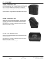
DCC (DC COMPARTMENT COVER)
The DCC covers the DC terminal area and allows a space which can be used to
mount other components such as a DC current shunt. The DCC can be used
with or without the DCA.
When installing an FX with a PS4DC or PS2DC disconnect enclosure, both the
DCA and DCC (or Turbo) are required.
The DCC is provided with all VFX inverter/chargers.
Installation & Programming Manual
FX & VFX Series Inverter/Charger System
900-0027-1
Page 14
Rev 7.2
08/26/05
Copyright 2003 OutBack Power Systems, Inc.
19009 62nd Ave NE, Arlington WA 98223 USA
Tel 360 435 6030
Fax 360 435 6019
TURBO KIT INFORMATION
The Turbo Kit is an addition that is either included or can be added to any sealed FX. Typically, the Turbo Kit adds 300-500 watts of
power to a sealed FX. This extra power is included in the model number for sealed FXs that come with Turbos. If the sealed FX did
not come with a Turbo and one is added, then the FX will be able to produce the extra 300-500 watts of power in addition to the power
that the model number indicates. Do not use the Turbo with a vented VFX! It will actually reduce the output power of the VFX!
The Turbo is highly recommended in hot climates or for installations that can use a few hundred watts of extra power. In hot climates or
when the FX is the primary charging device, the chances of the FX overheating are heightened. When the FX gets to its temperature
limits, it will back off the charging process to avoid overheating (and a shutdown of the FX). The Turbo Kit solves this problem by
directing air over the casting and its fins, thus causing better convection cooling of the FX.
The signal powering the Turbo Kit fan comes from the auxiliary output of the FX. The default setting of the auxiliary output is set to
“CoolFan” which starts the Turbo Kit automatically when the FX starts heating up.
The instructions for adding a Turbo Kit are included with the Turbo Kit or the FX. If you are also automatically starting a generator using
the auxiliary output, you can program the auxiliary output to “GenAlert” or use the Advanced Generator Start (AGS) system and parallel
the generator start wires with the Turbo Kit wires. When the generator is running the Turbo Kit is also running. This solution works
because the FX gets hottest when it is charging. If the paralleling of the generator and the Turbo Kit doesn’t work properly, adding a
470 uF (micro Farad) electrolytic capacitor (found at your local electronics shop) across the auxiliary output will solve this problem.
Copyright 2003 OutBack Power Systems, Inc.
19009 62nd Ave NE, Arlington WA 98223 USA
Tel 360 435 6030
Fax 360 435 6019
FX & VFX Series Inverter/Charger System
Installation & Programming Manual
900-0027-1
Rev 7.2
08/26/05
Page 15
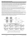
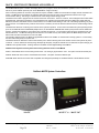
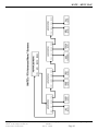
HUB COMMUNICATION MANAGER
The HUB communication manager allows the MATE to control and monitor a maximum of ten OutBack products. Currently the HUB
comes in two types. The HUB-4 can connect up to four Outback products (FX’s and/or MX-60’s). The HUB-10 (shown below) can
connect up to ten Outback products (FX’s and/or MX-60’s). The FX’s can be operated in a stacked or independent configuration. If the
FX’s are to be stacked, the HUB must be part of the system. In a stacked configuration, the Master FX must be plugged into port #1 of
the HUB. The Slave inverters must use the following ports (example: for 8 inverters and 2 MX-60’s, the Master must be plugged into
Port 1, and the seven Slaves must be plugged into Ports 2-8. The MX-60’s can use Ports 9&10). Future OutBack products will also be
compatible with the HUB. When using the HUB, the MATE must be plugged into the 1st MATE port of the HUB.
The HUB manages both the inter-FX communications and the MATE-FX communication.
When a HUB is used in conjuncture with the RTS, the RTS (Remote Temperature Sensor) must be plugged into the Master FX which
must be plugged into port 1 of the HUB. If this is the case, only one RTS is required for all devices plugged into the HUB.
When two or more FX’s are stacked in a series or parallel configuration, the system automatically turns off any excess slave FX’s to
save power and maximize conversion efficiency. This power save system is fully automatic and works with or without the MATE
connected to the system. Some programming is required when more than two FXs are stacked together. See the STACKING
INFORMATION section of this manual for more information.
Currently on 3-phase systems there is a limit of one FX per phase (totaling three FX’s). To convert the HUB into 3-phase mode, you
must move the jumper on the HUB to the “3-PH” position. See the HUB instruction manual for details.
One MATE system controller and display can be connected to the HUB. Although there are two Mate ports on the HUB, only the 1st
Mate port is currently operational. The MATE can be located up to 1000 feet (305 meters) from the HUB / system location. Cabling
from the HUB to the MATE is completed using standard CAT-5 type ethernet cable with RJ45 modular 8 conductor jacks. This wiring is
considered to be low voltage / limited energy circuitry. Refer to the MATE manual for more information on the MATE.
All cabling from the FX and MX60 communication ports to the HUB is made with CAT-5 type ethernet cabling. The maximum distance
from the HUB-4 to the FX or MX-60 should be less than 10 feet. OutBack includes two 3-foot (1 meter) and two 6-foot (2 meter) long
CAT-5 cables standard with the HUB-4. OutBack includes two 3-foot (1 meter) long and four 6-foot (2 meter) long CAT-5 cables
standard with the HUB-10. Check with your OutBack dealer for additional cables.
MATE
MX60
MX60
HUB-10
SLAVE
SLAVE
SLAVE
MASTER
SLAVE
SLAVE
SLAVE
SLAVE
A total of up to ten OutBack products plus one MATE displays can be used with a HUB-10 (shown above).
The HUB-4 will only accept four OutBack products plus one MATE.
NOTE: There is a limit of ten FX’s when operated as a stacked system.
Installation & Programming Manual
FX & VFX Series Inverter/Charger System
900-0027-1
Page 16
Rev 7.2
08/26/05
Copyright 2003 OutBack Power Systems, Inc.
19009 62nd Ave NE, Arlington WA 98223 USA
Tel 360 435 6030 Fax 360 435 6019
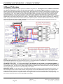
FX SYSTEM CONFIGURATIONS
The FX System Configuration section shows diagrams of some typical system configurations using the FX. These diagrams are for
non-Mobile FX installations only. Below these diagrams are notes for how to change each diagrams to accommodate a
Mobile installation. There are diagrams for a single FX, two FX’s in series or series/parallel (see NOTE below), two FX’s in parallel,
four FX’s in series/parallel (see NOTE below), four FX’s in parallel, and a 3-phase system. The diagrams show the proper breakers
and wiring for the AC side of the installations as well as connections to the HUB, MATE and X-240 (if applicable). Also included is
information on the maximum continuous power of the systems and proper DC breaker sizes. This information is dependent on whether
the FX’s are sealed or vented and on the system’s battery voltage.
NOTE: Stacking FX’s in series/parallel means that there are FX’s directly connected to two separate 120VAC output legs. These two
120VAC output legs produce 240VAC between them (the series portion). By connecting the X-240 autotransformer between the two
120VAC output legs, these legs are magnetically coupled (indirectly connected). This allows all of the FX’s to power either of the
120VAC output legs (the parallel portion). Series/parallel stacking requires the use of the X-240 autotransformer and must use
“OutBack” stacking programming.
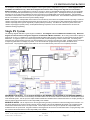
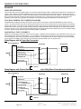
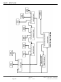
Single FX System
The following diagram illustrates a typical single FX installation. This diagram is for a non-Mobile FX installation only. Below this
diagram are notes for how to change this diagram to accommodate a Mobile installation. All AC wiring must handle a capacity of
50 amps AC or more. For ‘Mobile’ FX’s, a 30A input breaker should be used due to the maximum AC input pass-through rating of the
Mobile FX’s. A single FX system can continuously power 2-3.6KW of loads depending on which model is used. Connecting more
power than the continuous rating of the FX may cause breakers to trip or the FX to shut off its AC output. A MATE must be connected
to adjust any parameters or to display any meters. Once the FX has been programmed using the MATE, the MATE can be
disconnected. The programming will be saved within the FX’s non-volatile memory even if the FX is completely shut down.
NON-MOBILE FX NOTES: The AC OUTPUT NEUTRAL IS NOT BONDED TO THE CHASSIS OR THE GROUND TERMINAL of
the FX system. This connection is to be made by the installer either in the AC service entrance or within the AC load distribution panel
of the electrical system. The AC input, AC output and DC terminals are isolated from the metal chassis of the FX. Proper grounding of
these circuits and the chassis of the FX is the responsibility of the installer.
MOBILE FX NOTES: The AC input source to the FX (grid and/or generator) must have an internal neutral-ground connection. On
the above diagram the AC source’s neutral conductor must go directly to the FXs AC NEUTRAL IN terminal or to a separate neutral
busbar that is isolated from the FX’s AC output neutral. The AC output of the FX must go to a separate AC output busbar that is
isolated from the AC input neutral. A bypass mechanism must bypass the AC source’s hot and neutral wires. Proper grounding of the
DC circuit and the chassis of the FX is the responsibility of the installer.
Copyright 2003 OutBack Power Systems, Inc.
19009 62nd Ave NE, Arlington WA 98223 USA
Tel 360 435 6030
Fax 360 435 6019
FX & VFX Series Inverter/Charger System
Installation & Programming Manual
900-0027-1
Rev 7.2
08/26/05
Page 17
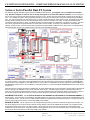
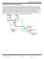
FX SYSTEM CONFIGURATION – SERIES OR SERIES/PARALLEL DUAL FX SYSTEM
Series or Series/Parallel Dual FX System
The following diagram illustrates a typical series FX installation using two FX’s. This diagram is for a non-Mobile FX installation
only. Below this diagram are notes for how to change this diagram to accommodate a Mobile installation. The AC wiring from
the AC source and to the AC loads must handle 50 amps AC or more. All other AC wiring must handle a capacity of 50 amps AC or
more. For a ‘Mobile’ FX system, 30A input breakers should be used due to the maximum AC input pass-through rating of the Mobile
FX’s. This type of FX system can continuously power 4-7.2KW of loads depending on which model is used. Connecting more power
than the continuous rating of the FX may cause breakers to trip or the FX to shut off its AC output. A HUB and a MATE must be
connected to stack these FX’s in series. The MATE must be connected to adjust any parameters or to display any meters. The slave
FX must be programmed through the MATE as a ‘Classic Slave’ (series stacking, no X-240) or as ‘OB Slave L2’ (series/parallel
stacking, X-240 included). Once the FX has been programmed using the MATE, the MATE can be disconnected. The programming
will be saved within the FX’s non-volatile memory even if the FX is completely shut down.
NOTES: The X-240 autotransformer (located at the top-middle of the diagram) should never be used in a system that is programmed
for “Classic” stacking. If an X-240 is connected between two 120 VAC output legs, program the top FX as Master (1-2PH MASTER)
and the lower FX as an OutBack L2 slave (OB SLAVE L2). If the X-240 is not included in the system program the top FX as Master (12PH MASTER) and the lower FX as an OutBack L2 slave (OB SLAVE L2). See the STACKING INFORMATION section of the manual
for more info.
When the FX’s are connected in series for 120/240 VAC, the X-240 autotransformer can be connected to the AC output to allow both of
the FX’s capacity to be available on either of the 120 VAC output circuits. This allows higher efficiency and better performance as
heavy 120 VAC loads are powered by both of the FX’s. The X-240 autotransformer also allows the master to power loads on either of
the 120 VAC output circuits with the slave off. This reduces the idle power consumption and improves the system efficiency.
NON-MOBILE FX NOTES: The AC OUTPUT NEUTRAL IS NOT BONDED TO THE CHASSIS OR THE GROUND TERMINAL of
the FX system. This connection is to be made by the installer either in the AC service entrance or within the AC load distribution panel
of the electrical system. The AC input, AC output and DC terminals are isolated from the metal chassis of the FX. Proper grounding of
these circuits and the chassis of the FX is the responsibility of the installer.
MOBILE FX NOTES: The AC input source to the FX (grid and/or generator) must have an internal neutral-ground connection. On
the above diagram the AC source’s neutral conductor must go directly to the FXs AC NEUTRAL IN terminal or to a separate neutral
busbar that is isolated from the FX’s AC output neutral. The AC output of the FX must go to a separate AC output busbar that is
isolated from the AC input neutral. A bypass mechanism must bypass the AC source’s hot and neutral wires. Proper grounding of the
DC circuit and the chassis of the FX is the responsibility of the installer.
Installation & Programming Manual
FX & VFX Series Inverter/Charger System
900-0027-1
Page 18
Rev 7.2
08/26/05
Copyright 2003 OutBack Power Systems, Inc.
19009 62nd Ave NE, Arlington WA 98223 USA
Tel 360 435 6030 Fax 360 435 6019
FX SYSTEM CONFIGURATION – PARALLELED DUAL FX SYSTEM
Paralleled Dual FX System
The following diagram illustrates a typical paralleled FX installation using two FX’s. This diagram is for a non-Mobile FX installation
only. Below this diagram are notes for how to change this diagram to accommodate a Mobile installation. The AC wiring from
the AC source and to the AC loads must handle 100 amps AC or more. All other AC wiring must handle a capacity of 50 amps AC or
more. For a ‘Mobile’ FX system, 30A input breakers should be used due to the maximum AC input pass-through rating of the Mobile
FX’s. This type of FX system can continuously power 4-7.2KW of loads depending on which model is used. Connecting more power
than the continuous rating of the FX may cause breakers to trip or the FX to shut off its AC output. A HUB and a MATE must be
connected to stack these FX’s in parallel. The MATE must be connected to adjust any parameters or to display any meters. Once the
FX has been programmed using the MATE, the MATE can be disconnected. The programming will be saved within the FX’s nonvolatile memory even if the FX is completely shut down.
NOTES: Program the top FX as Master (1-2PH MASTER) and the lower FX as an OutBack L1 Slave (OB SLAVE L1). See the
STACKING INFORMATION section of the manual for more info.
NON-MOBILE FX NOTES: The AC OUTPUT NEUTRAL IS NOT BONDED TO THE CHASSIS OR THE GROUND TERMINAL of
the FX system. This connection is to be made by the installer either in the AC service entrance or within the AC load distribution panel
of the electrical system. The AC input, AC output and DC terminals are isolated from the metal chassis of the FX. Proper grounding of
these circuits and the chassis of the FX is the responsibility of the installer.
MOBILE FX NOTES: The AC input source to the FX (grid and/or generator) must have an internal neutral-ground connection. On
the above diagram the AC source’s neutral conductor must go directly to the FXs AC NEUTRAL IN terminal or to a separate neutral
busbar that is isolated from the FX’s AC output neutral. The AC output of the FX must go to a separate AC output busbar that is
isolated from the AC input neutral. A bypass mechanism must bypass the AC source’s hot and neutral wires. Proper grounding of the
DC circuit and the chassis of the FX is the responsibility of the installer.
Copyright 2003 OutBack Power Systems, Inc.
19009 62nd Ave NE, Arlington WA 98223 USA
Tel 360 435 6030
Fax 360 435 6019
FX & VFX Series Inverter/Charger System
Installation & Programming Manual
900-0027-1
Rev 7.2
08/26/05
Page 19
FX SYSTEM CONFIGURATION – SERIES/PARALLEL QUAD FX SYSTEM
Series/Parallel Quad FX System
The following diagram illustrates a typical series/parallel FX installation using four FX’s. This diagram is for a non-Mobile FX
installation only. Below this diagram are notes for how to change this diagram to accommodate a Mobile installation. The AC
wiring from the AC source and to the AC loads must handle 120 amps AC or more. The AC wiring connected to the QUO 100A dual
bypass breakers must handle 100 amps AC or more. All other AC wiring must handle a capacity of 50 amps AC or more. For a
‘Mobile’ FX system, 30A input breakers should be used due to the maximum AC input pass-through rating of the Mobile FX’s. This type
of FX system can continuously power 8-14.4KW of loads depending on which model is used. Connecting more power than the
continuous rating of the FX may cause breakers to trip or the FX to shut off its AC output. A HUB, MATE and X-240 must be connected
to successfully stack these FX’s in series/parallel. The MATE must be connected to adjust any parameters or to display any meters.
Once the FX’s have been programmed using the MATE, the MATE can be disconnected. The programming will be saved within the
FX’s non-volatile memory even if the FX is completely shut down.
NOTES: Program the top FX as the Master (1-2PH MASTER), the first Slave as an Outback L1 slave (OB Slave L1), and the second
and third Slaves as OutBack L2 slaves (OB SLAVE L2). See the STACKING INFORMATION section of the manual for more info.
In systems that include three or more FX’s and must be series stacked, an X-240 autotransformer must be used. When the FX’s are
connected in series for 120/240 VAC, the X-240 can be connected to the two AC output legs to allow all of the FX’s capacity to be
available on either of the 120 VAC output circuits. This allows higher efficiency and better performance as heavy 120 VAC loads are
powered by more of the FX’s. The X-240 also allows the master to power loads on either of the 120 VAC output circuits with the slave
off. This reduces the idle power consumption and improves the system efficiency.
NON-MOBILE FX NOTES: The AC OUTPUT NEUTRAL IS NOT BONDED TO THE CHASSIS OR THE GROUND TERMINAL of
the FX system. This connection is to be made by the installer either in the AC service entrance or within the AC load distribution panel
of the electrical system. The AC input, AC output and DC terminals are isolated from the metal chassis of the FX. Proper grounding of
these circuits and the chassis of the FX is the responsibility of the installer.
MOBILE FX NOTES: The AC input source to the FX (grid and/or generator) must have an internal neutral-ground connection. On
the above diagram the AC source’s neutral conductor must go directly to the FXs AC NEUTRAL IN terminal or to a separate neutral
busbar that is isolated from the FX’s AC output neutral. The AC output of the FX must go to a separate AC output busbar that is
isolated from the AC input neutral. A bypass mechanism must bypass the AC source’s hot and neutral wires. Proper grounding of the
DC circuit and the chassis of the FX is the responsibility of the installer.
Installation & Programming Manual
FX & VFX Series Inverter/Charger System
900-0027-1
Page 20
Rev 7.2
08/26/05
Copyright 2003 OutBack Power Systems, Inc.
19009 62nd Ave NE, Arlington WA 98223 USA
Tel 360 435 6030 Fax 360 435 6019
FX SYSTEM CONFIGURATION – PARALLEDED QUAD FX SYSTEM
Paralleled Quad FX System
The following diagram illustrates a typical paralleled FX installation using four FX’s. This diagram is for a non-Mobile FX installation
only. Below this diagram are notes for how to change this diagram to accommodate a Mobile installation. The AC wiring from
the AC source and to the AC loads must handle 200 amps AC or more. The AC wiring connected to the QUO 100A dual bypass
breakers must handle 100 amps AC or more. All other AC wiring must handle a capacity of 50 amps AC or more. For a ‘Mobile’ FX
system, 30A input breakers should be used due to the maximum AC input pass-through rating of the Mobile FX’s. This type of FX
system can continuously power 8-14.4KW of loads depending on which model is used. Connecting more power than the continuous
rating of the FX may cause breakers to trip or the FX to shut off its AC output. A HUB and a MATE must be connected to stack these
FX’s in parallel. The MATE must be connected to adjust any parameters or to display any meters. Once the FX has been programmed
using the MATE, the MATE can be disconnected. The programming will be saved within the FX’s non-volatile memory even if the FX is
completely shut down.
NOTES: Program the top FX as Master (1-2PH MASTER) and the three lower FX’s as OutBack L1 Slaves (OB SLAVE L1). See the
STACKING INFORMATION section of the manual for more info.
NON-MOBILE FX NOTES: The AC OUTPUT NEUTRAL IS NOT BONDED TO THE CHASSIS OR THE GROUND TERMINAL of
the FX system. This connection is to be made by the installer either in the AC service entrance or within the AC load distribution panel
of the electrical system. The AC input, AC output and DC terminals are isolated from the metal chassis of the FX. Proper grounding of
these circuits and the chassis of the FX is the responsibility of the installer.
MOBILE FX NOTES: The AC input source to the FX (grid and/or generator) must have an internal neutral-ground connection. On
the above diagram the AC source’s neutral conductor must go directly to the FXs AC NEUTRAL IN terminal or to a separate neutral
busbar that is isolated from the FX’s AC output neutral. The AC output of the FX must go to a separate AC output busbar that is
isolated from the AC input neutral. A bypass mechanism must bypass the AC source’s hot and neutral wires. Proper grounding of the
DC circuit and the chassis of the FX is the responsibility of the installer.
Copyright 2003 OutBack Power Systems, Inc.
19009 62nd Ave NE, Arlington WA 98223 USA
Tel 360 435 6030
Fax 360 435 6019
FX & VFX Series Inverter/Charger System
Installation & Programming Manual
900-0027-1
Rev 7.2
08/26/05
Page 21
FX SYSTEM CONFIGURATION – 3 PHASE FX SYSTEM
3-Phase FX System
The following diagram illustrates a typical 3-phase FX installation using three FX’s. This diagram is for a non-Mobile FX installation
only. Below this diagram are notes for how to change this diagram to accommodate a Mobile installation. This system will
produce 120VAC per phase and 208VAC from phase to phase. At this time there can only be one FX per phase on a 3-phase system.
The AC wiring from the AC source and to the AC loads must handle 50 amps AC or more. All other AC wiring must handle a capacity
of 50 amps AC or more. For a ‘Mobile’ FX system, 30A input breakers should be used due to the maximum AC input pass-through
rating of the Mobile FX’s. This type of FX system can continuously power 6-10.8KW of loads depending on which model is used.
Connecting more power than the continuous rating of the FX may cause breakers to trip or the FX to shut off its AC output. A HUB and
a MATE must be connected to stack these FX’s in 3-phase. The MATE must be connected to adjust any parameters or to display any
meters. A jumper in the HUB must be moved to let the system operate in 3-phase. Check the HUB manual for instructions. Once the
FX has been programmed using the MATE, the MATE can be disconnected. The programming will be saved within the FX’s nonvolatile memory even if the FX is completely shut down.
NOTES: Program the top FX as Master (3PH MASTER) and the two lower FX’s as 3-phase Slaves (3PH SLAVE). See the
STACKING INFORMATION section of the manual for more info. The 3-phase system is a 120/208 VAC Y-connected power system.
The AC source must also be a 120/208 VAC Y-connected 3-phase source.
NON-MOBILE FX NOTES: The AC OUTPUT NEUTRAL IS NOT BONDED TO THE CHASSIS OR THE GROUND TERMINAL of
the FX system. This connection is to be made by the installer either in the AC service entrance or within the AC load distribution panel
of the electrical system. The AC input, AC output and DC terminals are isolated from the metal chassis of the FX. Proper grounding of
these circuits and the chassis of the FX is the responsibility of the installer.
MOBILE FX NOTES: The AC input source to the FX (grid and/or generator) must have an internal neutral-ground connection. On
the above diagram the AC source’s neutral conductor must go directly to the FXs AC NEUTRAL IN terminal or to a separate neutral
busbar that is isolated from the FX’s AC output neutral. The AC output of the FX must go to a separate AC output busbar that is
isolated from the AC input neutral. A bypass mechanism must bypass the AC source’s hot and neutral wires. Proper grounding of the
DC circuit and the chassis of the FX is the responsibility of the installer.
Installation & Programming Manual
FX & VFX Series Inverter/Charger System
900-0027-1
Page 22
Rev 7.2
08/26/05
Copyright 2003 OutBack Power Systems, Inc.
19009 62nd Ave NE, Arlington WA 98223 USA
Tel 360 435 6030 Fax 360 435 6019
START-UP & OPERATION
Once the FX system installation is completed, it is time to power the system. Leave the breakers on the AC side in the OFF position
until the FX’s are powered and programmed. Power the FX’s (and any MX-60 charge controllers) by switching the DC disconnect
breakers to the ON position. The LED’s (Light Emitting Diodes) in the AC compartment of each FX will begin to light. For each FX, one
“BATTERY” LED will be lit. This “BATTERY” LED should be either the green “FULL” LED or yellow “OK” LED. If the red “LOW” LED is
lit, check the battery voltage and the battery-to-FX cabling for reasons why the FX thinks the batteries are low. The other set of
“STATUS” LED’s will begin to light. The red “ERROR” LED may blink a few times, but this is just a symptom of powering the FX.
About 5 seconds to 10 seconds after power is applied, the green “INVERTER” LED should be lit and the “AC IN” and “ERROR” LED’s
should not be lit.
At this point, the FX is producing an AC output voltage, or inverting, hence the reason the “Inverter” LED is lit. If the user were to
connect AC loads to the FX, the FX would use battery power to produce AC power to power the loads. Before doing this, the
programming of the FX should be performed using the MATE. If applicable, this programming should include the following:
•
Choose the AC input type of grid or generator. Generator is the default. See the SETUP MENU page in the ADVANCED
section for more info.
•
Stacking of multiple FX’s. See the STACKING INFORMATION and the STACKING INSTRUCTION sections for proper setup
info. Also see the STACKING MENU in the ADVANCED section for programming info.
•
Adjust the charging set points using the battery manufacturers specification. See the BATTERY CHARGING INFORMATION
section to directions and familiarity of the FX’s charging process. Also see the CHARGER MENU in the ADVANCED section
for programming info.
•
Set the time and the date on the MATE (see MATE manual).
•
Program the Auxiliary output for the function you wish it to perform. If you wish to automatically start a generator, see the
AUTOMATIC GENERATOR START section of this manual (you may also need the MATE manual). In any case, also see the
AUXILIARY MENU in the ADVANCED section of this manual for programming info.
•
Perform any other programming that you wish in the ADVANCED section of this manual.
The FX system is now ready to perform per your specification. Switch the AC output breakers on with the bypass mechanism switched
to “Normal”. If there are X-240 breakers switch them on at this time. Next, switch on the AC input breakers. Provided that the AC
source to the FX’s is available, the yellow “AC IN” LED in the AC compartment will begin to blink. If the voltage of the utility grid or
generator is within 108 vac to 140 vac and the frequency is within 54 Hz to 66 Hz, the FX will connect to the utility grid or generator.
This process takes about 30 seconds and the “AC IN” LED will stop blinking and stay lit when connection occurs.
When the “AC IN” LED is lit, the AC transfer switch within the FX is activated and the utility grid or generator power is applied to the
loads. At this time the FX will perform a charge on the batteries. The charging process is different depending on whether the generator
has been started automatically or manually. The start of either charging process will “Bulk” (raise) the battery voltage until they reach
the “Absorb” voltage. The FX will maintain this “Absorb” voltage for the “Absorb Time Limit” (default of 1 hour). If the generator had
been automatically started, the generator will now be shut off. However, if the generator had been manually started the charging
process continues. After the “Absorb” stage, the FX goes into “Silent” mode, letting the battery voltage drop until it levels out. If the
battery voltage drops to the “Re-Float” voltage the FX will perform a “Float” charge. It raises the battery voltage to the “Float” voltage
and it then sustains this voltage for the “Float Time Period” (default of 1 hour). Once this hour is up, the FX will go back into “Silent”
mode, and again wait for the battery voltage to drop to “Re-Float”. This process of “Silent”, “Re-Float”, “Float, “Silent”, “Re-Float”, etc.
will continue until the generator is manually shut off.
Copyright 2003 OutBack Power Systems, Inc.
19009 62nd Ave NE, Arlington WA 98223 USA
Tel 360 435 6030
Fax 360 435 6019
FX & VFX Series Inverter/Charger System
Installation & Programming Manual
900-0027-1
Rev 7.2
08/26/05
Page 23
BATTERY CHARGING INFORMATION
A battery bank may last for over 10 years if properly cared for, but it can also be ruined in less than a month if not properly charged.
Batteries represent a large percentage of the cost of a system. Keeping your battery bank healthy is very important.
BATTERY CHARGING SETPOINTS
It is necessary for the system operator to gather the following information from the battery manufacturer:
•
The ‘Absorb’ Voltage
•
The ‘Float’ Voltage
•
The ‘Equalize’ Voltage
If you don’t obtain and enter this information into the MATE, you could be overcharging or undercharging the batteries. The FX’s
default charging settings are set to low values to protect from overcharging of the batteries so, to be safe, make the call. These
‘Absorb’, ‘Float’, and ‘Equalize’ voltage set points as well as the ‘Absorb Time Period’ should be programmed into the FX through the
MATE in the ADV/FX/CHARGER menu section. To access this section, refer to the “Menu Map” and “Charger Menu” located in the
“MATE SCREENS” section of this manual.
A Note on the Absorb Setting:
Some battery manufacturers recommend a low ‘Absorb’ voltage and a long ‘Absorb Time Period’, claiming that this will extend the life of
the batteries. This may be true, but remember that the longer the ‘Absorb Time Period’ the longer your generator will run. The cost for
gas and the wear on the generator may outweigh the projected loss of life on your batteries. Since most of the charge gets put back
into the batteries before they reach the ‘Absorb’ voltage, a higher ‘Absorb’ voltage may be better. This means more battery
maintenance (watering) and more gassing (always vent the batteries out of the building) but will save you money on gas and generator
repairs. Please ask the battery manufacturer for the maximum ‘Absorb’ voltage of the batteries.
BATTERY EQUALIZATION
In order to make sure the batteries stay healthy, they should not be discharged over 50% and should be regularly charged back to nearfull capacity. For flooded lead-acid batteries, full capacity is only achieved by equalizing the batteries. Sealed batteries should never
be equalized unless specifically recommended by the battery manufacturer. An ‘Equalize’ charge should be performed every one to six
months depending on how deep and how often your batteries get discharged. The FX will not automatically perform an ‘Equalize’
charge. The user must use the MATE to manually start an Equalize charge. Check with the battery manufacturer for proper
equalizing instructions.
RTS – THE REMOTE TEMPERATURE SENSOR
The “Temperature Compensated Battery Voltage” is on the MATE screen – Main / Status / FX / Batt / Down. When an RTS is
plugged into the system, the ‘Absorb’, ‘Float’ and ‘Equalize’ voltage set points are temperature compensated. The ‘Refloat’ voltage,
generator-start set points and all low-battery voltage initializations are not temperature compensated.
BATTERY CHARGING SEQUENCE
The following diagram shows the algorithm that the FX uses to charge the batteries. When an AC voltage source is connected to the
FX’s AC input terminals, the FX will connect in about 30 seconds (default setting) and pass the AC voltage from the AC source through
the FX’s AC transfer switch to the loads connected to the FX’s AC output terminals. When an AC voltage source connects to the FX, a
battery charging sequence begins.
Installation & Programming Manual
FX & VFX Series Inverter/Charger System
900-0027-1
Page 24
Rev 7.2
08/26/05
Copyright 2003 OutBack Power Systems, Inc.
19009 62nd Ave NE, Arlington WA 98223 USA
Tel 360 435 6030 Fax 360 435 6019
BATTERY CHARGING INFORMATION
The following bullets describe the steps in the battery charging sequence.
•
The first stage of the charging sequence is the “Bulk” stage. The FX uses as much AC current as possible from the AC input
source to raise the battery voltage to the “Absorb” voltage setting. See the “Maximum Current for Battery Charging” heading in
the RATINGS section for the FX’s default and maximum values of the AC current used for charging. The time period of the
“Bulk” stage will vary with the battery bank’s age, capacity, voltage and AC source.
•
Once the “Absorb” voltage has been reached, the FX will use the necessary AC current to sustain this voltage for the “Absorb
Time” (default of 1 hour). The AC current will decrease as the “Absorb” charge continues.
•
After the “Absorb Time Period”, the FX goes into “Silent” mode. The charger is turned off and the FX continues to monitor the
battery voltage. If a generator has been automatically started on a low voltage condition using AGS (see MATE manual), the
FX will automatically turn off the generator after the “Absorb Time Period”.
•
If a generator has been manually started or the utility grid is connected, the FX will let the battery voltage drop to the “Refloat”
voltage and then it will start a ‘Float’ charge.
•
The ‘Float’ stage will raise the battery voltage to the “Float Setpoint” for the “Float Time Limit”. The ‘Float’ stage is meant for
maintaining batteries that have DC loads connected to them. If there aren’t any DC loads on the batteries, the battery voltage
will usually remain above the “Refloat” voltage set point.
•
After the “Float Time Limit” (default of 1 hour), the FX goes back into ‘Silent’ mode and waits until the battery voltage drops to
the ‘Refloat’ voltage again. It then repeats the ‘Float’ charge for the “Float Time Period”. The FX will continue this cycle of
‘Silent’, ‘Refloat’ and ‘Float’ until the AC source is disconnected.
BATTERY CHARGING CONSTRAINTS
There are some settings and situations that affect the battery charging process. These settings and situations are described by the
following bullets.
•
Rated Continuous Current of the AC Input Source: This applies to generators only since the utility grid can produce power
levels much higher. This setting is for the maximum AC generator current (at 120 VAC) that the FX will accept before is turns
down its charger. This setting is called “AC/2 Gen Limit” and can be accessed through the MATE by following the path Main /
Setup / FX / Input / Down / Down. The rated continuous AC current of the generator should be set in this screen. When the
combined AC current used by the FX’s charger and the loads connected to the FX’s AC output exceed this “AC/2 Gen Limit”
the FX will reduce the AC current used for the charger to ensure that the generator is not overloaded.
•
Low AC Input Voltage: When the FX is connected to an AC input source, it passes through the AC input sources’ voltage and
current. The FX has minimum and maximum voltage settings for the AC input source to ensure that the AC input source does
not damage downstream loads with low or high voltage. If the FX is charging and passing through power, the AC input source
voltage can be dragged down to the FX’s low voltage limit. When this happens, the FX will back off the charger to sustain an
acceptable voltage. If the FX goes below the low voltage limit, it will disconnect from the AC input source and cease charging.
If you are experiencing low AC input voltage from a generator it is possible to adjust some generators to raise their voltage.
•
External “Dump Load” is Limiting Battery Voltage: Many systems include sources of power that vary depending on the
weather, such as wind turbines and micro-hydro systems. In high wind or water conditions, these power sources can produce
voltages above what the battery bank should handle. These systems often use “Dump Loads” to get rid of this extra power at
a particular battery “Dump” voltage. Sometimes the battery “Dump” voltage is below the FX’s ‘”Target” voltage (‘”Target’’
voltage refers to a voltage set point that the FX is trying to reach; like “Absorb”, “Float” or “Equalize”). If the “Dump” voltage is
below the “Target” voltage, the FX will never reach the “Target” because the “Dump Load” limits the battery voltage. The FX
will continue to try to charge the batteries to the “Target” voltage while the “Dump Load” will continue to “Dump” the FX’s
charging power. Since the FX wants to complete a charge, it will be stuck charging. This can cause a generator to run until it
runs out of gas or, if connected to the utility grid, it can cause a lot of unnecessary power consumption ($$$). To remedy this
situation, reduce the FX’s “Target” voltage to a value slightly below the “Dump Load” voltage or raise the “Dump Load” voltage
above the FX’s “Target” voltage (remember not to overcharge the batteries).
•
AC Input Voltage is Different on Different Legs: In systems that have multiple AC input legs (120/240 VAC split phase or
120/208 VAC three phase) there are often slightly different voltages present on each leg. This is more likely with generators
since their power is small compared to the utility grid. When the AC voltage on one leg is reduced to the FX’s AC input “Lower
Limit”, the FX(‘s) connected to that particular leg will reduce their charging current so as not to disconnect from the AC input
source. This is a similar situation as the “Low AC Input Voltage” bullet above but with multiple AC input legs. The other FXs
on the other AC input legs will not reduce their charging rates unless they too have reached a “Lower Limit” voltage condition.
•
Temperature Limit is Reached: Each FX has three temperature sensors that measure the temperature of the FX’s
capacitors, FETs, and transformer. These temperature sensors will indicate when a temperature has been reached that will
adversely affect the FX’s operation. At these temperatures, the FX will back off the charger to reduce the temperature to a
sustainable level. If you notice that the FX is not charging as hard as you think it should and the FX is very hot to the touch
(and it gets hot!) you can be assured that the FX is limiting the charge due to heat.
•
Battery Voltage “Target” is Reached: In a system that has only one FX, that FX will back off the charger when it reaches a
“Target” voltage (“Target” voltage is either “Absorb”, “Float” or “Equalize”). In a system with multiple FX’s, the “Slave” FX’s will
back off before the “Master” FX, leaving the “Master” FX to finish the charge.
Copyright 2003 OutBack Power Systems, Inc.
19009 62nd Ave NE, Arlington WA 98223 USA
Tel 360 435 6030
Fax 360 435 6019
FX & VFX Series Inverter/Charger System
Installation & Programming Manual
900-0027-1
Rev 7.2
08/26/05
Page 25
STACKING INFORMATION
Classic, OutBack, and 3-Phase Stacking Methods
OutBack Power Systems offers four different ways to stack multiple FX’s (up to 10 for single or split phase systems, only 3 for threephase systems). The first thing to consider is if you want all of the FX’s in parallel (FX’s on same AC Output Leg producing 120VAC
only), in series (FX’s divided between two AC Output Legs producing 120VAC on each Leg and 240VAC between the two Legs), or in
3-phase (maximum of three FX’s, one on each AC Output Leg, producing 120VAC on each Leg and 208VAC between each set of
Legs). A HUB-4 or HUB-10 must be included to stack FX’s.
If you choose to stack the FX’s in series, the second thing to consider is how many FX’s you will use. If you are series stacking three
to ten FX’s, you must use “OutBack” stacking and include an X-240 autotransformer. If you are series stacking only two FX’s, you can
choose between “Classic” stacking and “OutBack” stacking. Keep in mind that if you choose to series stack FX’s using “OutBack”
stacking, you must include an X-240 autotransformer in the system. Below is an explanation of each type of system.
The next four pages explain the Stacking menu and how to program the various types of stacked systems.
PARALLEL (OUTBACK): This stacking method pertains to a system that has two to ten FX’s all connected to the same 120VAC
Output Leg. The system can be programmed such that only one FX (the Master) stays “On” and the rest of the FX’s (the Slaves) are
asleep. The Slaves come on only when the power requirement is high enough that the Master FX calls on the Slave FX’s to help with
the load. It is also possible to program the system to keep any number of FX’s “On” while the remaining FX’s are asleep. The AC Input
source (usually a generator or utility grid) must be 120VAC or stepped-down to 120VAC form a 240VAC source using the X-240
autotransformer.
SERIES (CLASSIC): This stacking method pertain to a system that has only two FX’s and two 120VAC Output Legs that will produce
240VAC between them. In this system the Master FX and the Slave FX operate independently from each other. In other words, each
FX will power its own 120VAC Output Leg but if any 240VAC loads need to be powered both FX’s will be used. The AC Input source
(generator or grid) must be 240VAC for both Legs to be powered.
SERIES (OUTBACK): This stacking method pertains to a system that has two to ten FX’s connected to two 120VAC Output Legs that
will produce 240VAC between them. In this stacking method the FX’s will be connected to either of the two AC Output Legs (usually
half of the FX’s on each Leg). Connected between the AC Output Legs will be an X-240 autotransformer that gets installed in the
PSAC (or PS2AC). The X-240 can perform two operations that a “classically” stacked system cannot perform and can handle more
that two FX’s. First, it can produce 240VAC from one Leg if that 240VAC load is small enough. This saves power in the long run by
keeping the FX’s on the other Leg in “sleep” mode. Secondly, the X-240 allows each FX to power loads on the Leg of which it is not
directly connected. This allow the Master FX on Leg 1 to power loads on Leg 2 without “waking” and Slave FX’s unnecessarily. The
biggest advantage is that this system is very tolerant of imbalanced loads on the two 120 vac Legs on the AC output. By the magic of
the X-240 autotransformer, together with the control method used in the FX, the AC loads are balanced on the two Legs automatically.
This maximizes the efficiency of the FX system and allows larger loads to be operated without overloading one of the FX’s. The AC
Input source (generator or grid) must be 240VAC for both Legs to be powered and for no faults to occur.
3-PHASE: This stacking method pertains to a system that has three FX’s connected to three 120VAC Output Legs that will produce
208VAC between any two Legs of the 3-phase system. In this stacking method only three FX’s can be used. Each of the three FX’s
will be connected to its own 120VAC Output Leg. To set the system up properly an adjustment to the HUB is necessary. Within the
HUB is a jumper that needs to be changed in order for the system to operate correctly. See the HUB manual for instructions on this
procedure. The AC Input source (generator or grid) must be a 120VAC/208VAC 3-phase source connected to the AC Input terminals of
the three FX’s.
X-240 AUTOTRANSFORMER CAPACITY
The X-240 autotransformer option is rated at 4000 VA continuously and consumes about 12 watts. The PSAC and PS2AC enclosures
include mounting for this option and the PSAC (not the PS2AC) also includes a space to allow the addition of two 12 vdc powered 4
inch muffin fans to increase the continuous power rating of the X-240. This fan can be powered directly from the AUX output of an FX
when the AUX output function has been programmed for “COOLFAN” (default) mode. This enables the 12 vdc fan to turn on
automatically when the FX’s are powering heavy loads. With the additional air flow on the X240, it can handle a maximum of 6000 VA
continuously. The X-240 option includes a 25 amp, 2-pole circuit breaker which is rated for 100% continuous duty applications. It may
be necessary to use two X-240’s in systems that include more than four FX’s (depending on how much power needs to be transferred
from one AC Output Leg to the other AC Output Leg).
In the balancing transformer application with series stacked inverters, the X-240 is able to transfer up to 3000 VA from one of the 120
VAC output legs to the other 120 VAC output leg. Power higher than 3000 watts can be transferred through the X-240 for starting loads
that require large surges but should not be used on a continuous basis.
Installation & Programming Manual
FX & VFX Series Inverter/Charger System
900-0027-1
Page 26
Rev 7.2
08/26/05
Copyright 2003 OutBack Power Systems, Inc.
19009 62nd Ave NE, Arlington WA 98223 USA
Tel 360 435 6030 Fax 360 435 6019
STACKING INSTRUCTIONS
Stacking Procedure
This section will help inform you on how to set up stacking correctly and what the screens in the stacking menu mean. (Remember, for
3-phase stacking a jumper must be set to the 3-ph position in the HUB. See HUB manual for further information.) Make sure that the
FX’s connect to the lowest numbered ports of the HUB. First, turn off all AC breakers (the Bypass breaker can be left on). Next, turn
on all FX’s using their DC breakers and verify that the MATE recognizes all FX’s. You can verify this by watching the MATE go through
its boot-up sequence. The MATE’s boot-up sequence will show the following screens: (1) “G’day Mate!” (2) “OutBack Power Systems”
(3) Version (4) “HUB Found” (5) Hub ports and the OutBack devices connected to them. Screen (5) will allow you to verify that the
MATE sees all of the FX’s. If it doesn’t see all of the FX’s or if you aren’t sure, you can do one of two things. Either disconnect and
reconnect the MATE to the HUB or do a re-poll with the MATE. A re-poll on the MATE can be done by following the path MAIN /
SETUP / MATE / PG2 / COMM / REPOLL (see the MATE manual for proper operation of the MATE). Once you are sure that the
MATE recognizes all the FX’s connected to the HUB, you must access the “STACK” menu. This can be found on the MATE by
following the path MAIN / ADV / any button (this screen serves as a warning only) / PASSWORD (press the INC and DEC
buttons until the number is 141 and then press ENTER) / FX / PG2 / PG3 / STACK. You are now in the menu used for stacking
FX’s. Before continuing we will inform you on what each screen pertains to, the possible selections of that screen and how to choose
the next FX for proper programming.
STACK PHASE
The “Stack Phase” screen establishes which FX is the master and which FX’s follows the master’s commands. Each FX has a default
of “1-2ph Master” (one or two phase Master). The FX on port 1 of the HUB is always a Master (and usually the only Master), otherwise
the MATE will give a communication error. For a single phase or split (two) phase system, the FX in port 1 of the HUB should remain a
“1-2ph Master”. For a 3-phase system, the FX on port 1 of the HUB must be changed to a “3ph Master” (this procedure will be
explained soon). To select the next FX connected to the HUB, press the PORT button on the MATE. In the upper right-hand corner of
the MATE’s screen is the “port” indicator. It will display a “P” followed by a number indicating the port it is controlling (for example “P01”
indicates port 1, the Master FX’s port). Repeatedly pressing PORT on the MATE will cycle through the ports on the HUB that have FX’s
connected to them. Stop when you have reached a port that has an FX on it that needs to be a Slave. By pressing the INC (increase)
and DEC (decrease) buttons on the MATE, you can select the proper type of Slave that is appropriate for your system. Below are the
different selections in the STACK PHASE menu with a description of what they do.
1-2 PH MASTER: 1-2 PH MASTER is used for stand-alone (one) FX systems OR as the MASTER of a single phase or split
phase system. Set the stack phase of the FX you want as the master to ‘1-2 PH Master’ (if it isn’t already) and make sure it is in
port 1 of the HUB. It is acceptable to have every FX connected to the HUB be a “1-2ph Master”. If this is the case, each FX must
be connected to a separate AC Output Leg (both Hot and Neutral). The master FX is always considered to be the L1 phase.
CLASSIC SLAVE: If you have a system with two FX’s that you wish to produce 240VAC with but without an X-240
autotransformer, set the stack phase of the FX you want as the slave to “Classic Slave” and make sure it is in port 2 of the hub.
“Classic” stacking is meant for 120/240 vac systems where each FX handles their own 120 volt phase. The combination of the two
FX’s creates 240 volts to run 240 loads. If this FX is set to ‘Classic Slave’ then its output is 180 degrees out of phase from the
master and is considered to be the L2 phase. Classic stacking can only stack two FX’s and there is no load sharing which is
possible with ‘OutBack’ stacking.
OB SLAVE L1: Single Phase: If you have a system with two to ten FX’s and you wish to produce 120VAC on the same AC
Output Leg, set the stack phase of the FX’s you want as the slaves to “OB Slave L1” and make sure that they are in the lowest
numbered ports of the HUB. “OB Slave L1” is used for FX’s that run in parallel with the master. These FX’s are considered the L1
phase. Split Phase: Alternately, if you have a system with two to ten FX’s and an X-240 autotransformer and you wish to produce
120VAC on both AC Output Legs and also 240VAC between the two AC Output Legs then set the stack phase of the FX’s you
want as parallel slaves (Leg 1) to “OB Slave L1”. Make sure the slave FX’s are in the lowest numbered ports of the HUB. “OB
Slave L1” is used for FX’s that run in parallel with the master. OutBack’s X-240 autotransfromer must be included in the system to
use the split-phase stacking option. This FX is considered the L1 phase.
OB SLAVE L2: If you have a system with two to ten FX’s and an X-240 autotransformer and you wish to produce 120VAC on
both AC Output Legs and also 240VAC between the two AC Output Legs then set the stack phase of the FX’s you want as series
slaves (Leg 2) to “OB Slave L2”. Make sure the slave FX’s are in the lowest numbered ports of the HUB. “OB Slave L2” is used
for FX’s that run in series with the master. OutBack’s X-240 autotransfromer must be included in the system to use this stacking
option. This FX is considered L2 phase.
3PH MASTER: If you have a system with three (and only three) FX’s and you wish to produce 120VAC on three AC Output Legs
as well as 208VAC between each AC Output Leg, set the stack phase of the FX you want as the master to “3PH Master” and make
sure it is in port 1 of the HUB. The 3-phase stacking is similar to “Classic” stacking in the sense that each FX acts independently
and cannot help out other phases. The HUB also has a jumper on it that needs to be changed for 3-phase stacking (refer to the
HUB manual). This FX is considered phase A.
3PH SLAVE: If you have a system with three (and only three) FX’s and you wish to produce 120VAC on three AC Output Legs
as well as 208VAC between each AC Output Leg, set the stack phase of the 2 FX’s you want as the slaves to “3PH Slave” and
make sure they are in ports 2 and 3 of the HUB. There are no selections to differentiate between phases B and C. When you set
the jumper in the HUB for 3-phase, the HUB tells each slave which phase they are. “3PH slave” on HUB port 2 is considered
phase B. “3PH slave” on HUB port 3 is considered phase C.
Copyright 2003 OutBack Power Systems, Inc.
19009 62nd Ave NE, Arlington WA 98223 USA
Tel 360 435 6030
Fax 360 435 6019
FX & VFX Series Inverter/Charger System
Installation & Programming Manual
900-0027-1
Rev 7.2
08/26/05
Page 27
STACKING INSTRUCTIONS
Stacking Procedure (Continued)
The next two screens in the “Stack” menu on the MATE are the “POWER SAVE LEVEL MASTER ADJUST ONLY” and “POWER SAVE
LEVEL SLAVE ADJUST ONLY” screen. You can access these screens by pressing DOWN once or twice if you are currently on the
STACK PHASE screen. Since nobody (seriously, even here at OutBack) understands these screens the first 3-4 times they are
explained, we offer our best effort right here. These screens only make complete sense after you’ve read and understand both of them.
These two screens only pertain to systems that have “OB Slave L1” and “OB Slave L2” type slaves.
POWER SAVE LEVEL MASTER ADJUST ONLY
Only adjust the value on this screen if you wish to have one or more of the Slave FX’s AC outputs “On” at all times. This may be
necessary if you wish to have instantaneous power on Leg 2 or are having trouble starting large loads. The first thing to note is that this
screen pertains to the Master FX only and therefore you must be on port 1 (P01 in the upper right-hand corner of the MATE). Press
PORT on the MATE until you see P01 on the MATE. The number to the right of the screen is the “Slave Rank Designator”. The default
value for the Slave Rank Designator is zero (0) on every FX. By pressing INC on the MATE you can increment (by whole numbers) this
value. If this value is set to a number greater than zero then the Master FX will keep the Slave FX’s AC outputs “On” if they have a
“POWER SAVE LEVEL SLAVE ADJUST ONLY” value equal to or less than this number (for instance, if this value is set to “2” then all
the Slaves with “POWER SAVE LEVEL SLAVE ADJUST ONLY” values of “1” or “2” will have their AC outputs kept “On”). Any Slave
with a “POWER SAVE LEVEL SLAVE ADJUST ONLY” value greater than the Masters “POWER SAVE LEVEL MASTER ADJUST
ONLY” value will be “asleep” (AC output is “Off”) until the Master calls upon it to help with large loads.
POWER SAVE LEVEL SLAVE ADJUST ONLY
This screen allows you to assign the “Slave Rank” of the Slave FX’s in the system. The first thing to note is that this screen pertains to
the Slave FX’s only and therefore you must be on port 2 or greater on the MATE (shown in the upper right-hand corner of the MATE as
P02 or P03, etc.). Press PORT on the MATE until you see the port that you wish to program displayed on the MATE. The number to
the right of the screen is the “Slave Rank”. All Slave FX’s have “POWER SAVE LEVEL SLAVE ADJUST ONLY” (or “Slave Rank”)
default values of 1. If this value is not changed from 1 then one of two things will happen. First, if the Master FX has been
programmed with a value of 1 or greater in the “POWER SAVE LEVEL MASTER ADJUST ONLY” screen then all of the Slave FX’s
(with “Slave Rank” = 1) will remain “On” at all times. Second, if the Master FX has been programmed with a value of zero in the
“POWER SAVE LEVEL MASTER ADJUST ONLY” screen then all of the Slave FX’s will remain “Off” until the Master FX needs help
and calls for the Slave FX’s with “Slave Rank” equal to 1 to come “On”. This will turn on all of the Slaves. If your system includes more
than one Slave FX then will want to choose a different “Slave Rank” for each Slave FX. This allows them to come “On” one at a time
which saves power in the long run. To change the “Slave Rank” of a given Slave FX, press the PORT button on the MATE until the
Slave FX’s port appears in the upper right-hand corner of the MATE. Next, press INC to increase the value until it is what you desire.
Repeat this process for each Slave in the system. When a Slave FX has a “POWER SAVE LEVEL SLAVE ADJUST ONLY” value
greater than the Master FX’s “POWER SAVE LEVEL MASTER ADJUST ONLY” it will remain “Asleep” (and save about 18 watts).
When large loads are present, the Master FX will call out for “Slave Rank” = 1 to come “On” (unless it is already “On” due to the
“POWER SAVE LEVEL MASTER ADJUST ONLY” setting being 1 or greater). If the Master FX needs even more power then it will call
out for “Slave Rank” = 2 to come “On” and so on.
Using these three screens will allow you to stack your system in many different configurations. As an addition to the explanations
above, we have offered some examples of common systems outlined below.
System Examples
DUAL-STACKED SYSTEM USING “CLASSIC” STACKING
This type of system will include only two FX’s and must be set up as described here. Turn off all AC Output and AC Input breakers
before powering up FX’s. In a dual stack, I am assuming that the top FX is plugged into port 1 of the HUB and the 2nd FX down is
plugged into port 2 (the location of the FXs is not a rule, just for simplicity). Using the MATE, go to the stacking menu (explained earlier
in the “Stacking Instructions” section). You are now at the 1st stacking menu called “Stack Phase”. In the upper right hand corner of
the mate screen will always be the HUB port number of the FX you’re working with at the time. Let’s start out with the FX that’s on port
1. If something other than P01 appears in the upper right hand corner then press the PORT button until P01 appears. Set the “Stack
Phase” of the port 1 FX to “1-2 PH Master”. Press the PORT button and verify that the label in the upper right hand corner displays
P02. We are still in the “Stack Phase” menu but we are now talking to the FX on port 2. Push the INC button once to set the “Stack
Phase” to “Classic Slave”. Now you’ve set 1 FX (P02) to be in series with the master (P01). The next two screens in the STACK menu
do not apply to a Classically stacked system, so you need not worry about them. Have fun with your system!
STACKED SYSTEM USING OUTBACK’S “PARALLEL” STACKING
This type of system may have between 2 and 10 FX’s that will have their AC Outputs connected to the same Leg. We will be using a
Quad-Stacked (4 FX) system as an example. If you have less than four FX’s then any reference to FX’s on ports greater than the
amount of FX’s in your system will not apply to your system. If you have more than four FX’s then follow the natural pattern of
programming that will become apparent in this example.
In a quad stack, I am assuming that the top FX is plugged into port 1 of the HUB, the 2nd FX down is plugged into port 2, the 3rd FX
down is plugged into port 3, and the 4th FX down is plugged into port 4 (again, location of the FXs is not a rule, just for simplicity).
Installation & Programming Manual
FX & VFX Series Inverter/Charger System
900-0027-1
Page 28
Rev 7.2
08/26/05
Copyright 2003 OutBack Power Systems, Inc.
19009 62nd Ave NE, Arlington WA 98223 USA
Tel 360 435 6030 Fax 360 435 6019
STACKING INSTRUCTIONS
System Examples (Continued)
Using the MATE, go to the stacking menu (explained earlier in the “Stacking Instructions” section). You are now at the 1st stacking
menu called “Stack Phase”. In the upper right hand corner of the mate screen will always be the HUB port number of the FX you’re
working with at the time. Let’s start out with the FX that’s on port 1. If something other than P01 appears in the upper right hand corner
then press the PORT button until P01 appears. Set the “Stack Phase” of the port 1 FX to “1-2 PH Master”. Press the PORT button and
verify that the label in the upper right hand corner displays P02. We are still in the “Stack Phase” menu but we are now talking to the
FX on port 2. Push the INC button two times to set the “Stack Phase” to “OB Slave L1”. Press the PORT button again to talk to the FX
on port 3. Push the INC button two times to set the “Stack Phase” to “OB Slave L1”. Press the PORT button again to talk to the FX on
port 4. Push the INC button two times to set the “Stack Phase” to “OB Slave L1”. Now you’ve set 3 FX’s (P02-P04) to be in parallel
with the master (P01). If you have more FX’s in the system then program them as “OB Slave L1”.
Press the DOWN button 2 times to get into the “POWER SAVE LEVEL SLAVE ADJUST ONLY” menu. Press the PORT button until
P02 is displayed in the upper right corner of the screen. This menu pertains to the slaves only which is why we’re starting out with port
2. The setting from the factory should be already set to 1 which is the 1st rank slave. If it’s anything other than 1 appears press the INC
or DEC buttons to make it 1. Press the PORT button to talk to the port 3 FX. Press the INC button to change the “power save level
slave adjust only” to 2 which is the 2nd rank slave. Press the PORT button to talk to the port 4 FX. Press the INC button until the
setting is 3 for 3rd rank slave. Now you’ve set the rank for all the slaves. If you have more FX’s in the system then press the PORT
button to access the next FX and press INC until the number on the screen is 1 number less than the port number (i.e. if you are on
P05, the number on the screen should be 4).
Let’s back track a little by going to the “POWER SAVE LEVEL MASTER ADJUST ONLY” menu. Do this by pressing the DOWN
button, TOP button, then DOWN button. Verify that the screen you are on now is the “POWER SAVE LEVEL MASTER ADJUST
ONLY” screen and change the port to P01. Turn on all of your FX’s AC Output breakers. The master FX’s “Inverter” LED should be
solid and all the slaves “Inverter” LED’s should be blinking. Adjust the “POWER SAVE LEVEL MASTER ADJUST ONLY” from 0 to 1
and watch the 1st slave’s “Inverter” LED go solid. When the “Inverter” LED is on solid, this means that the inverter is on. When the
“Inverter” LED on the slave is blinking, this means the FX is asleep. Adjust the “POWER SAVE LEVEL MASTER ADJUST ONLY” to 2
nd
rd
and watch the 2 slave’s “Inverter” LED turn on. Adjust the “POWER SAVE LEVEL MASTER ADJUST ONLY” to 3 and watch the 3
slave’s “Inverter” LED turn on. If you have more than three slaves then keep increasing the value in the “POWER SAVE LEVEL
MASTER ADJUST ONLY” screen and verify that each slave’s “Inverter” LED comes on as expected. You have now verified that all
FX’s are stacked correctly so adjust the “POWER SAVE LEVEL MASTER ADJUST ONLY” back down to 0 and have fun with your
system!
STACKED SYSTEM USING OUTBACK’S “SERIES / PARALLEL” STACKING
This type of system may have between 2 and 10 FX’s that will have their AC Outputs connected to one of two Legs. I am assuming
that half of the FX’s will be connected to each AC Output Leg. Actually, it is acceptable to divide the FX’s between the two Legs in the
way you see fit, but at least one FX must be on each Leg. We will be using a Quad-Stacked (4 FX) system with two FX’s on each Leg
in this example. When we set an FX as “OB Slave L1” this indicates that it is in parallel (on the same Leg) with the master FX. When
we set an FX as “OB Slave L2” this indicates that it is in series (on the opposite Leg) with the master FX. If you have a different amount
of FX’s than the four FX’s in our example or if you are overloading one Leg of your system, then you might be putting the slave FX’s on
different Legs than what is shown in the example. We will try to alleviate any confusion when we get to the part of the process where
this is important. The sentences in italics are intended for instructions on systems that are different than the example.
nd
rd
In a quad stack, I am assuming that the top FX is plugged into port 1 of the HUB, the 2 FX down is plugged into port 2, the 3 FX
th
down is plugged into port 3, and the 4 FX down is plugged into port 4 (again, the location of the FXs is not a rule, just for simplicity).
st
Using the MATE, go to the stacking menu (explained earlier in the “Stacking Instructions” section). You are now at the 1 stacking
menu called “Stack Phase”. In the upper right hand corner of the mate screen will always be the HUB port number of the FX you’re
working with at the time. Let’s start out with the FX that’s on port 1. If something other than P01 appears in the upper right hand corner
then press the PORT button until P01 appears. Set the “Stack Phase” of the port 1 FX to “1-2 PH Master”. Press the PORT button and
verify that the label in the upper right hand corner displays P02. We are still in the “Stack Phase” menu but we are now talking to the
FX on port 2. Push the INC button two times to set the “Stack Phase” to “OB Slave L1”
If you have a system with only two FX’s or you wish to put the FX connected to port 2 in series with the master, push the INC button
one additional time (three times total) to set the “Stack Phase” to “OB Slave L2”.
Press the PORT button again to talk to the FX on port 3. Push the INC button three times to set the “Stack Phase” to “OB Slave L2”
If you wish to put the FX connected to port 3 in parallel with the master, push the INC button only two times to set the “Stack Phase” to
“OB Slave L1”.
Press the PORT button again to talk to the FX on port 4. Push the INC button three times to set the “Stack Phase” to “OB Slave L2”.
Again, if you wish to put the FX connected to port 3 in parallel with the master, push the INC button only two times to set the “Stack
Phase” to “OB Slave L1”. Any additional FX’s in the system can be programmed by pressing the PORT button to get to the next FX
and then press INC two times (“OB Slave L1”) for parallel stacking or press the INC button three times for series stacking. In this
example, we’ve set 1 FX (P02) to be in parallel with the master (P01) and 2 FX’s (P03 & P04) to be in series with the master.
Press the DOWN button 2 times to get into the “POWER SAVE LEVEL SLAVE ADJUST ONLY” menu. This menu allows you to set
the order in which the slave FX’s come “On”. Press the PORT button until P03 is displayed in the upper right corner of the screen.
We’re starting out with port 3 because the FX on port 3 is the first slave that is in series (“OB Slave L2”) with the master.
Copyright 2003 OutBack Power Systems, Inc.
19009 62nd Ave NE, Arlington WA 98223 USA
Tel 360 435 6030
Fax 360 435 6019
FX & VFX Series Inverter/Charger System
Installation & Programming Manual
900-0027-1
Rev 7.2
08/26/05
Page 29
STACKING INSTRUCTIONS
System Examples (Continued)
By making this FX the 1st rank slave, we are turning both Legs “On” directly, thus producing 240VAC without using the X-240.
If you have a system that is different from this example then press the PORT button until you get to a slave FX that is in series (“OB
Slave L2”) with the master.
On this screen the setting from the factory should be set to 1 which indicates the 1st rank slave. If it’s anything other than 1 then press
the DEC button until it becomes 1. Press the PORT button until you reach P02 to talk to the port 2 FX.
If you have a system that is different from this example then press the PORT button until you get to a slave FX that is in parallel (“OB
Slave L1”) with the master.
Press the INC button to change the “POWER SAVE LEVEL SLAVE ADJUST ONLY” to 2 which is the 2nd rank slave. Press the PORT
button twice to talk to the port 4 FX.
If you have a system that is different from this example then press the PORT button until you get to the next slave FX that is in series
(“OB Slave L2”) with the master.
Press the INC button until the setting is 3 for 3rd rank slave.
Any additional FX’s in the system can be programmed by pressing the PORT button to get to the next FX and then press INC until the
setting is 4 for the 4th rank slave. Continue this process, making sure each FX has its own “Slave Rank”, until you have set all FX’s.
Let’s back track a little by going to the “POWER SAVE LEVEL MASTER ADJUST ONLY” menu. Do this by pressing the DOWN
button, TOP button, then DOWN button. Verify that the screen you are on now is the “POWER SAVE LEVEL MASTER ADJUST
ONLY” screen and change the port to P01. Turn on all of your FX’s AC Output breakers. The master FX’s “Inverter” LED should be
solid and all the slaves “Inverter” LED’s should be blinking. Adjust the “POWER SAVE LEVEL MASTER ADJUST ONLY” from 0 to 1
st
and watch the 1 slave’s (port 3) “Inverter” LED go solid. When the “Inverter” LED is on solid, this means that the inverter is on. When
the “Inverter” LED on the slave is blinking, this means the FX is asleep. Adjust the “POWER SAVE LEVEL MASTER ADJUST ONLY”
to 2 and watch the 2nd slave’s (port 2) “Inverter” LED turn on. Adjust the “POWER SAVE LEVEL MASTER ADJUST ONLY” to 3 and
watch the 3rd slave’s (port 4) “Inverter” LED turn on. If you have more than three slaves then keep increasing the value in the “POWER
SAVE LEVEL MASTER ADJUST ONLY” screen and verify that each slave’s “Inverter” LED comes on as expected. You have now
verified that all FX’s are stacked correctly so adjust the “POWER SAVE LEVEL MASTER ADJUST ONLY” back down to 0 and have
fun with your system!
3-PHASE STACKED SYSTEM (3 FX’S ONLY)
This type of system will include only three FX’s and must be set up as described here. Turn off all AC Output and AC Input breakers
before powering up FX’s. In 3-phase stacking, I am assuming that the top FX is plugged into port 1 of the HUB, the 2nd FX down is
rd
plugged into port 2 and the 3 FX down is plugged into port 3 (This is not a rule, just for simplicity). The HUB has a jumper on it that
needs to be changed for 3-phase stacking (refer to the HUB manual). Using the MATE, go to the stacking menu (explained earlier in
the “Stacking Instructions” section). You are now at the 1st stacking menu called “Stack Phase”. In the upper right hand corner of the
mate screen will always be the HUB port number of the FX you’re working with at the time. Let’s start out with the FX that’s on port 1.
If something other than P01 appears in the upper right hand corner then press the PORT button until P01 appears. Set the “Stack
Phase” of the port 1 FX to “3ph Master”. The Master FX is considered phase A. Press the PORT button and verify that the label in the
upper right hand corner displays P02. We are still in the “Stack Phase” menu but we are now talking to the FX on port 2. Push the INC
button five times to set the “Stack Phase” to “3ph Slave”. Now you’ve set this FX (P02) as phase B, producing 208VAC between itself
and the master (P01). Press the PORT button again and verify that the label in the upper right hand corner displays P03. We are still
in the “Stack Phase” menu but we are now talking to the FX on port 3. Push the INC button five times to set the “Stack Phase” to “3ph
Slave”. Now you’ve set this FX (P03) as phase C, producing 208VAC between itself and the master (P01) and also 208VAC between
itself and the FX on phase B. The next two screens in the STACK menu do not apply to a 3-phase system, so you need not worry
about them. Remember that the AC input to a 3-phase system must be a 3-phase source (generator or grid). Have fun with your
system!
Installation & Programming Manual
FX & VFX Series Inverter/Charger System
900-0027-1
Page 30
Rev 7.2
08/26/05
Copyright 2003 OutBack Power Systems, Inc.
19009 62nd Ave NE, Arlington WA 98223 USA
Tel 360 435 6030 Fax 360 435 6019
AUTOMATIC GENERATOR START INSTRUCTIONS
The Aux output of the FX can be programmed to start a 2-wire gas or diesel generator automatically when the batteries need charging.
There are two separate ways to accomplish this function; AGS (Advanced Generator Start) and GenAlert. AGS is a function of the
MATE while GenAlert is a function of the FX.
AGS has more features and therefore it can start the generator under many different types of conditions. The AGS features include
Quiet Time, Voltage Start, Load Start, Must Run, and Exercise. Since AGS is a function of the MATE see the MATE manual for
instructions. NOTE: The MATE must have a Code revision of 3.30 or greater (found on the third start-up screen of the MATE).
GenAlert is another way to automatically start the generator. It is programmed through the MATE but it doesn’t have all of the features
that AGS has. It works on a voltage start system where the generator will start when the battery voltage reaches a certain voltage for a
specific period of time and stop when the battery voltage reaches a higher voltage for a different period of time. These voltages and
time periods are programmed through the MATE. If you wish to use the GenAlert option, follow the instructions below. NOTE: If both
AGS and GenAlert are programmed, AGS will be used.
Starting from the main menu, press the <ADV> button to get into the advanced menu (the “password” is 141, press <INC> until the
number reads 141 and then press <ENTER>). From the Advanced menu press the <PG2> button then the <PG3> button, then the
<AUX> button to get into the auxiliary menu. The first screen that comes up is the “aux output control” which tells the FX to keep the
aux output off, on, or automatically do what the auxiliary output function is. In this case we want to keep the default setting on “AUTO”.
Press the <DOWN> button to get into the “aux output function” menu. This is the menu where we tell the auxiliary output what function
we want it to be. In this case we want it to start a generator. The default setting is “CoolFan” so press the <DEC> button 3 times so the
display reads “GenAlert”. Now that the function is set to start a 2-wire start generator, the start and stop parameters need to be set.
Press the <DOWN> button to get into the “genalert on setpoint” menu. This menu adjusts the battery voltage set point to where you
want the generator to start at. The default setting is 11, 22, or 44 volts (depending on your FX) which you can adjust. Press the <INC>
or <DEC> buttons to change this setting.
Press the <DOWN> button to get into the “genalert on delay” menu. This menu adjusts the time you will allow the battery to be at the
“genalert on setpoint” voltage before starting the generator. The default setting is 4 minutes at the “genalert on setpoint” and the
generator will start. Press the <INC> or <DEC> buttons to change this setting.
Press the <DOWN> button to get into the “genalert off setpoint” menu. This menu adjusts the battery voltage set point to where you
want to stop the generator. The default setting is 14, 28, or 56 volts (depending on your FX) which you can adjust. Press the <INC> or
<DEC> buttons to change this setting.
Press the <DOWN> button to get into the “genalert off delay” menu. This menu adjusts the time you will allow the battery to be at the
“genalert off setpoint” before stopping the generator. The default setting is 9 minutes at the “genalert off setpoint” and the generator will
stop. Press the <INC> or <DEC> buttons to change this setting.
Even though you have set the off function for the generator, there are two other ways that the auxiliary output can stop the generator. If
the charger settings of the FX reach float or silent mode, that overrides the “genalert off setpoint” because the FX figures that the
batteries are charged. The generator will turn off based on whatever comes first, genalert off, float, or silent. If you want to stop the
generator based on float or silent, either extend the “genalert off delay” beyond what is capable of the charger to achieve or raise the
“genalert off setpoint” higher than the “absorb setpoint” (default of 14.4, 28.8, or 57.6 volts depending on your FX).
The following schematic shows how to hook up a relay that interfaces with the 2-wire start generator. 3-wire start generators require an
adapter like the Atkinson GSCM available at: www.atkinsonelectronics.com.
Here are a couple of relays to use.
Most 12V relays will work of generator
starting. Select one between 2 and 30
amp contacts.
1) Radio Shack SPST 30 amp Auto
Relay #275-226
2) Grainger 10 amp SPDT relay #5ZH14
MFR: Omron #G2R-1-S-DC12
The socket for this relay is….
Grainger #6C898
MFR: Omron #P2RF-05-E
Copyright 2003 OutBack Power Systems, Inc.
19009 62nd Ave NE, Arlington WA 98223 USA
Tel 360 435 6030
Fax 360 435 6019
FX & VFX Series Inverter/Charger System
Installation & Programming Manual
900-0027-1
Rev 7.2
08/26/05
Page 31
MOBILE FX INFORMATION
General
GROUND SWITCHING
How it works: With no AC input signal present, the FX inverter’s Neutral Output is tied to Chassis Ground and hence to the Boat or RV
Ground. This is similar to any Home installation where one conductor (Neutral for the US) must be grounded. When an AC input is
applied and the inverter allows it to transfer, the Neutral Output to Ground bond within the inverter is broken. The Neutral Output line is
then connected to the Input’s Neutral and also the Ground of the Input source. At this point the FX inverter is using the Ground
supplied by shore power or the generator as its Neutral to Ground bond and this Ground becomes the inverters Ground.
STACKING MOBILE FX INVERTER/CHARGERS
The Master will be configured normally where the AC Input’s Ground is connected to the bussed GND-NEU connection of the FX
inverter. The slave inverters must have the buss removed and the Ground of the AC Input must be connected directly to the Chassis
Ground of the inverter. The reason for this configuration is that if each inverter has a bussed Neutral to Ground bond and any inverter
transfers sooner than the rest, the remaining inverters will have a different Neutral to Ground bond (One to the mobile Ground rather
than shore Ground). In this case there will be multiple Neutral to Ground bonds and the GFP breaker may blow if a noticeable voltage
is present. By removing the Neutral to Ground buss this problem is eliminated.
MAXIMUM AC INPUT CURRENT
Mobile FX inverter/chargers limit the AC input current to 30 amps. Outback Power has decided to do this because they use only on of
the three poles of the input relay within the FX. In a non-mobile FX, all three poles are used and can therefore carry three times the
current (theoretically, since they are paralleled this limit decreases). The mobile FX uses two poles of this relay for ground switching,
so only one pole is available. Due to this fact, we recommend a 30 amp breaker for the AC input to the FX.
Relay Diagram with AC Input Not Connected
AC Terminal Block
Input Relay
Output Relay
HOT AC IN
NEUTRAL IN
CHASSIS GROUND
BUSS
NEU-GND BOND
NEUTRAL OUT
HOT AC OUT
Ground
Relay Diagram with Ground Switched (Connected to Utility/Shore Power Neutral and Ground)
AC Terminal Block
Input Relay
Output Relay
HOT AC IN
NEUTRAL IN
CHASSIS GROUND
BUSS
NEU-GND BOND
NEUTRAL OUT
HOT AC OUT
Ground
Installation & Programming Manual
FX & VFX Series Inverter/Charger System
900-0027-1
Page 32
Rev 7.2
08/26/05
Copyright 2003 OutBack Power Systems, Inc.
19009 62nd Ave NE, Arlington WA 98223 USA
Tel 360 435 6030 Fax 360 435 6019
MOBLIE FX INFORMATION
Dual Input Transfer Switch Setup
In many cases, systems will have the option of using either an onboard generator or the utility grid (shore power) as their AC input.
When this is the case, both the AC “Hot” and AC “Neutral” lines must be connected to the appropriate source. Currently, OutBack
Power Systems does not produce a product that will accomplish this function. Therefore, the consumer must purchase a device that
accomplishes this task. The simplest form of this device is a double-pole, double-throw switch. The words “double-pole” indicates that
there are two connections, one for AC “Hot” and one for AC “Neutral”. The words “double-throw” indicate that there are two sets of
poles that can be contacted. This switch must be rated to handle the maximum AC voltage and AC current that it will see. When using
a “Mobile” FX with an onboard generator and a connection that can be made to “shore power”, refer to the diagram below. The
“Mobile” FX’s AC input consists of a Hot (H), Neutral (N) and Neu/Ground Bond (G). The “Mobile” FX has an internal “GroundSwitching Contact” that will open when it connects to an AC input. This allows the FX to make the neutral-ground bond when an AC
input is not connected yet, when an AC input connects, the neutral-ground bond will be released by the FX and made by the AC input.
If the system is 120/240 VAC with 120/240 VAC inputs, a Triple-Pole Double-Throw Switch is required.
Copyright 2003 OutBack Power Systems, Inc.
19009 62nd Ave NE, Arlington WA 98223 USA
Tel 360 435 6030
Fax 360 435 6019
FX & VFX Series Inverter/Charger System
Installation & Programming Manual
900-0027-1
Rev 7.2
08/26/05
Page 33
MATE - SYSTEM CONTROLLER AND DISPLAY
The OutBack MATE system controller and display allows you to program, control, and monitor the operation of one or more FX’s as
well as any other OutBack products (such as the MX60 MPPT charge controller).
When connecting a MATE to more than one product is required, a HUB-4 or HUB-10 communication manager must be included in the
system. The MATE can be located up to 1000 feet (300 meters) from the FX system using standard 8 conductor CAT-5 type
communication cabling. This wiring is considered to be a low voltage / limited energy circuit.
The MATE can be used to program the FX and then removed in most cases. There are, however, some settings that are located within
the MATE itself. Settings that require the use of the MATE’s time and date (programmable through the MATE) are stored within the
MATE and, therefore, the MATE must be connected to the FX or HUB for these setting to work. All of the settings pertaining only to the
FX are stored in non-volatile memory inside of the FX itself. The battery can then be disconnected from the FX and the settings will not
be lost.
The MATE also allows for monitoring and control of the FX system’s operation. Some of the more advanced system operating modes
(such as the HIGH BATTERY TRANSFER (HBX) function, the ADVANCED GENERATOR START (AGS) function and the GRID USE
function) requires that a MATE be connected to the FX system all of the time. To use these functions properly, the MATE’s time and
date should be set. The MATE’s settings are also stored in non-volatile memory and a battery within the MATE keeps the time and
date current when disconnected from an FX or the HUB.
The operating software used in the MATE is upgradeable to allow for the addition of new features to existing systems. It can be easily
removed and exchanged by the system user.
The MATE includes an RS-232 PC serial communication port to allow monitoring and remote modem access of the system via phone
or internet. This PC software is currently being developed by third party companies and will soon be offered as an option through your
OutBack Power Systems dealer. Tracking software is available at www.RightHandEng.com/OutBack.
Outback Power Systems currently offers the following different versions of the MATE:
“MATE”: Basic MATE with an oval encasing shown below. The casing is grayish white in color. This option includes an RS-232 port.
“MATE2”: Black flush mount version of the MATE shown below. This option includes an RS-232 port.
“MATE2M”: Black flush mount version with a simplified menu designed specifically for the Mobile market. Includes RS-232 access.
OutBack MATE System Controllers
“MATE”
Installation & Programming Manual
“MATE 2” & “MATE 2M”
FX & VFX Series Inverter/Charger System
900-0027-1
Page 34
Rev 7.2
08/26/05
Copyright 2003 OutBack Power Systems, Inc.
19009 62nd Ave NE, Arlington WA 98223 USA
Tel 360 435 6030 Fax 360 435 6019
MATE - SYSTEM CONTROLLER AND DISPLAY
OUTBACK MATE
System Controller and Display
Inverter
LED Indicator
(green)
AC Input
LED Indicator
(yellow)
Dedicated
Inverter
Control
“HOT” Key
Dedicated
AC Input
Control
“HOT” Key
“Soft” Keys
Each one of the soft keys corresponds to a word
on the bottom line of the LCD display
The menu system displayed on the MATE will vary depending on the software version that the MATE was
programmed with at the time of manufacturing or during its last software upgrade. For your particular menu system,
consult your MATE manual.
The following pages show the portion of the menu structure that relates to the FX. Most of the menu will be
consistent no matter what type of FX you have purchased. The MATE displays that follow are from the most current
MATE being sold by OutBack Power Systems.
The DC voltage values (the letters “vdc” usually follow these values) shown in the following MATE displays will be the
default values for a 12V version of the FX. For the 24V version, multiply these values by 2. For the 48V version,
multiply these values by 4. This multiplication process must be performed for the incremental values as well. When
changing a voltage setting you will use the ‘increment’ (INC) or ‘decrement’ (DEC) buttons. For example, for a 12V
FX the increment value is 0.1V. A 24V FX has an incremental value of 0.2V and a 48V FX has an incremental value
of 0.4V.
All values displayed in the “Setup” and “Advanced” menus are the default values unless otherwise stated.
For “M” versions of the MATE (example: MATE 2”M”), only the “Status” and “Advanced” menus are the same as non“M” versions of the MATE. If you are using an “M” version of the MATE, please consult the MATE manual for proper
navigation and screen information.
Copyright 2003 OutBack Power Systems, Inc.
19009 62nd Ave NE, Arlington WA 98223 USA
Tel 360 435 6030
Fax 360 435 6019
FX & VFX Series Inverter/Charger System
Installation & Programming Manual
900-0027-1
Rev 7.2
08/26/05
Page 35
MATE – SYSTEM CONTROLLER AND DISPLAY
This section of the manual will cover how to use the buttons on the MATE to navigate the menus.
NOTE: The menu system displayed on the MATE will vary depending on the software version that the MATE was
programmed with at the time of manufacturing or during its last software upgrade.
MENU STRUCTURE
MAIN MENU
The OutBack MATE uses a branching menu structure to display various
OutBack products operation modes and status. The menus are divided by
product type and are categorized by type of setting or by information being
displayed.
An example of the menu structure is shown to the right. All the screens that
show AC meters are grouped together in one menu tree allowing the user to
find the required meter with a minimum of button presses.
The top line of the MATE display will show the ‘path’ to the current menu; in
this example it is STATUS/FX/METERS.
STATUS
SETUP
MX
FX
METERS
BATTERY
OUTPUT
VOLTAGE
INPUT
VOLTAGE
INVERTER
CURRENT
STATUS/FX/METERS--------output
120 vac
voltage
DOWN UP TOP PORT
MATE BUTTONS
Port Designation
Menu Path = 1st Line
Menu Item = 2nd Line
&
rd
3 Line
SETUP/FX/INPUT---P00
ac transfer
GEN
control
DOWN GRID GEN PORT
Menu Item Value
th
Menu Choices = 4 Line
The MATE uses a six button user interface to navigate the menus and to change set points of various OutBack products.
Two buttons are dedicated to the FX and are labeled AC IN and INV. These buttons are special in that they can be pressed at any time
anywhere in the MATE menu structure, and they take you to the same screens. For this reason they are referred to as ‘Hot’ keys. Many
common functions that need to be accessed often are found under the AC IN and INV button.
The four lower buttons under the LCD are called ‘soft’ keys and are used for navigating around the menus and changing values. Each
‘soft’ key has various functions dependent on the label directly above it on the lower line of the LCD.
The 1st line on the MATE usually displays the path or location of where you are in the menu system. The 2nd and 3rd lines of the MATE
usually give you a description of what meter is being displayed or what parameter is currently set in the MATE. The words to the left of
the 2nd and 3rd lines should be read together while ignoring the “Menu Item Value” to the right. For instance, the parameter on the
th
above MATE screen should be read “ac transfer control” whose value is GEN. The 4 line on the MATE is almost exclusively used
th
for labels to the four soft keys below. Each button below the 4 line of the MATE’s display corresponds to the word directly above it.
This manual will denote soft key button presses as <BUTTON>, where BUTTON corresponds with the label displayed on the screen
directly above the soft key.
NOTE: Pressing the left two buttons simultaneously from anywhere
in the menu will return you to the MAIN menu screen.
Installation & Programming Manual
FX & VFX Series Inverter/Charger System
900-0027-1
Page 36
Rev 7.2
08/26/05
Copyright 2003 OutBack Power Systems, Inc.
19009 62nd Ave NE, Arlington WA 98223 USA
Tel 360 435 6030 Fax 360 435 6019
MATE – SYSTEM CONTROLLER AND DISPLAY
‘SOFT’ KEYS
The four buttons under the LCD are referred to as the ‘soft’ keys. Their operation is dependent on what their label says. The label is the
word on the bottom line of the LCD directly above the button.
Soft keys used to navigate the menus are commonly labeled <UP>, <DOWN>, <NEXT>, <BACK>, or <TOP>.
Soft keys that change settings are labeled either with the change they will make, such as : <OFF>, <AUTO>, and <ON>, or if there are
more then a couple values that the setting can be changed to, <INC> and <DEC> are used to mean increase and decrease,
respectively.
SETUP/FX/INPUT---P00
ac transfer
GEN
control
DOWN GRID GEN PORT
In this example, pressing <DOWN> will take you to the next set point screen in
the SETUP/FX/INPUT menu.
SETUP/FX/INPUT---P00
Input setup
completed
TOP SETUP MAIN
In this example, pressing <TOP> will take you to the first screen in the
SETUP/FX/INPUT menu. <SETUP> will return you to the SETUP/FX screen,
and <MAIN> will take you back to the Main screen.
SETUP/FX/INPUT---P00
ac transfer
GEN
control
DOWN GRID GEN PORT
In this example, pressing <GRID> will change the FX AC transfer control to
GRID mode. Conversely, pressing <GEN> will change the FX AC transfer
control to GEN mode.
SETUP/FX/INPUT---P00
ac1/grid
60.0 aac
limit
DOWN INC DEC PORT
In this example, pressing <INC> or <DEC> will change the numerical value of
the ac1/grid limit setting.
ADV/FX/AUX-------P00
aux output
CoolFan
function
DOWN INC DEC PORT
Copyright 2003 OutBack Power Systems, Inc.
19009 62nd Ave NE, Arlington WA 98223 USA
Tel 360 435 6030
Fax 360 435 6019
In this example, there are multiple operating modes for the aux output function.
Pressing <INC> or <DEC> will cycle through the available modes.
FX & VFX Series Inverter/Charger System
Installation & Programming Manual
900-0027-1
Rev 7.2
08/26/05
Page 37
MATE – SYSTEM CONTROLLER AND DISPLAY
Inverter Control
INV
The OutBack MATE includes an INV “hot” key to allow direct control of the inverter from anywhere in the menu system. The INV key is
located on the right side of the MATE LCD display. Pressing the INV key takes you to the INVERTER CONTROL menu shown below.
A green LED indicator is located above the INV key which flashes when the inverter is either in the search or power save modes and is
on continuously when full AC output voltage is available from the inverter. When the inverter is turned off the green LED will not be
illuminated.
INV
INVERTER CONTROL
currently:
ON
OFF
OK
SRCH
ON
Pressing the INV key once brings up the INVERTER CONTROL screen. To turn the inverter
ON, press the key located below the word ON. Selecting SRCH will cause the inverter to begin
operating in the search mode as long as the AC load connected is smaller than allowed by the
programming of the search function. Selecting OFF turns off the inverters AC output signal.
Select OK to return to the point in the menu system from where you entered the INVERTER
CONTROL screen.
Installation & Programming Manual
FX & VFX Series Inverter/Charger System
900-0027-1
Page 38
Rev 7.2
08/26/05
Copyright 2003 OutBack Power Systems, Inc.
19009 62nd Ave NE, Arlington WA 98223 USA
Tel 360 435 6030 Fax 360 435 6019
MATE – SYSTEM CONTROLLER AND DISPLAY
AC Input Control
AC IN
The OutBack MATE includes a AC IN “hot” key to allow direct control of the AC input from anywhere in the menu system. The AC IN
key is located on the left side of the MATE’s LCD display. Above the AC IN key is a yellow LED indicator which flashes when an AC
source is available but not connected, and is on continuously when the AC source is connected. If no AC source is available the yellow
LED indicator will remain off. The screens shown on this page apply to the “MATE”, the “MATE B” and the “MATE 2” only.
AC IN
Pressing the AC IN key once brings up the AC INPUT CONTROL screen. USE enables the
inverter to connect to the AC source when it is available. DROP disconnects the AC source
but will allow it to be reconnected if the battery gets too low or the inverter is overloaded.
AC INPUT CONTROL
currently:
USE
DROP
USE
AC IN
AC IN
OK
GEN START CONTROL
currently:
MAN-OFF
OFF
AC IN
AUTO
ON
AC IN
OK
AC IN
CHARGER CONTROL
currently:
OFF
AUTO
AC IN
AC IN
AUTO
OK
AC IN
EQ
Pressing the AC IN key a third time brings up the CHARGER CONTROL screen. This allows
operation of the battery charger to be preset for when an AC source is available. In AUTO
mode the charger will start charging when an AC source connects to the FX or when the FX
decides the batteries need charging. In OFF mode the charger stays off but the AC source is
still passed through to the loads.
AC IN
CHARGER MODE CONTROL
global charger mode
BULK
Pressing the AC IN key a second time brings up the GEN START CONTROL screen. This
allows operation of the generator either manually or automatically using the Advanced
Generator Start (AGS) functions. The generators starting circuitry must be connected to the
AUX ports of the control terminal block (see pages 11 & 12) to use this screen to manually turn
the generator ON or OFF or to let the FX automatically perform the AGS functions. When the
AGS functions have not been programmed, the screen will show MAN-OFF indicating that the
generator is controlled manually and is OFF. Pressing the ON button will change the screen
into MAN-ON and the generator will turn ON. To put this screen in AUTO mode, you must
access the AGS SETUP menu. See your MATE manual for details.
OK
Pressing the AC IN key a fourth time brings up the CHARGER MODE CONTROL screen. This
screen allows the MATE to issue system wide (global) charger commands. Both OutBack MX
and FX products will respond to global charger commands if they are connected through the
HUB.
Pressing <BULK> brings up the BULK CONTROL screen, it will allow the user to start and/or
stop a bulk charge cycle manually by pressing <START> or <STOP> respectively.
BULK CONTROL
Pressing <EQ> brings up the EQUALIZE CONTROL screen.
START
STOP
OK
When <START> has been selected, two informational screens are displayed. The user then
must answer <YES> before an equalize charging cycle is allowed to begin.
Once the equalizing process has started, you can stop it at anytime by selecting <STOP> from
this same control screen.
Copyright 2003 OutBack Power Systems, Inc.
19009 62nd Ave NE, Arlington WA 98223 USA
Tel 360 435 6030
Fax 360 435 6019
FX & VFX Series Inverter/Charger System
Installation & Programming Manual
900-0027-1
Rev 7.2
08/26/05
Page 39
MATE - MENU MAP
Installation & Programming Manual
FX & VFX Series Inverter/Charger System
900-0027-1
Page 40
Rev 7.2
08/26/05
Copyright 2003 OutBack Power Systems, Inc.
19009 62nd Ave NE, Arlington WA 98223 USA
Tel 360 435 6030 Fax 360 435 6019
MATE – MENU MAP
Copyright 2003 OutBack Power Systems, Inc.
19009 62nd Ave NE, Arlington WA 98223 USA
Tel 360 435 6030
Fax 360 435 6019
FX & VFX Series Inverter/Charger System
Installation & Programming Manual
900-0027-1
Rev 7.2
08/26/05
Page 41
MATE SCREENS
Summary Screen
The OutBack MATE includes a SUMMARY screen to allow easy understanding of the FX operation. The display uses both words and
symbols to show what currently is happening in the system, along with a limited amount of numbers. This makes it easier for the
system user to understand where the power is flowing within the system. The first line of the summary screen displays “DCÅÆAC”
and is measured in kilowatts (kW). This is to indicate the approximate AC power that is being both produced and consumed by all the
FX’s connected to the MATE (multiple FX’s can be connected to one MATE through the HUB). Basically, it shows how much work the
FX’s are doing and relates to energy being transferred between the FX’s and the batteries. The second line of the summary screen
displays ”AC Load” and has a light bulb symbol that appears for every 500 watts of power per FX that is being delivered to the AC
loads (so 1 one light bulb equals 1kW when two inverters are used with a single MATE). The third line displays four different things
depending of the status of the AC input. It displays “No ACIN” when the FX doesn’t sense an AC source present. It displays “AC Drop”
when an AC source is present but not connected. It displays “Buying” when an AC source is connected and the FX is using the source
to charge or pass-through to the loads. Finally, it displays “Selling” when the FX is pushing power back into the AC source (Grid-Tie
FX’s only). In the third line, the symbol used to denote 500 watts or power per inverter is a dollar sign. The fourth line of the summary
screen provides information about the battery (limited to battery voltage at this time).
To access the summary screen, press the button under the label SUM from the MAIN screen. Included below are some examples of
different summary screens with an explanation of the information represented.
MAIN---------------6:54:42P
SUM STATUS SETUP ADV
↓
DCÅÆAC . . . 0.0kW
AC Load . . . . . .
No ACIN . . . . . .
Battery
12.8V
The MAIN screen is where the menu system starts. The four words in the bottom line of the
display correspond to the four buttons located below the display. The word in BOLD on the
bottom line indicates the selection used to advance the display to the next screen. Pressing
the left two buttons simultaneously from anywhere in the menu will return you to this screen.
To access the summary screen, select SUM from the MAIN screen. A typical summary screen
is shown here for a FX when the inverter is off and no AC source is connected.
The battery voltage is provided in the lower right corner of the display.
EXAMPLES
DCÅÆAC >>> . 1.4kW
AC Load ☼☼☼ . . . .
No ACIN . . . . . .
Battery
12.1V
DCÅÆAC . . .
AC Load ☼☼ . .
Buying $$ . .
Battery
0.0kW
. . .
. . .
12.6V
INVERTING: The FX is inverting and producing AC output voltage which is powering 1.4kW of
AC loads. No AC source is connected to the inverter.
PASS-THROUGH: An AC source has been connected and the AC loads are drawing power
from the AC source that is passing through the FX. The top line shows 0.0 kW indicating that
the charger is in SILENT mode and is not charging the batteries. Approximately 1.0 kW loads
are being powered from the AC source (assuming the system consists of one FX).
DCÅÆAC >>> . 1.7kW
AC Load ☼ . . . . .
Buying $$$$. . . .
Battery
13.4V
BUYING (CHARGING & PASS-THROUGH): The FX is buying (four $ ≈ 2.0kW) more power
than it is delivering to the loads (one ☼ ≈ 0.5kW). This is an indication that the FX is using the
excess power to charge the batteries. The charger is charging at a rate of 1.7 kW of AC power
going into the battery. The AC loads are low and are being powered from the AC source.
DCÅÆAC >>>>> 2.5kW
AC Load ☼☼☼☼☼ . . .
AC Drop . . . . . .
Battery
12.3V
AC DROP: The inverter is on and powering 2.5 kW of AC load from the batteries. The AC
source is available but DROP was selected in the AC INPUT CONTROL. This will also be
displayed when an AC source is available but not in use, such as during the initial time delay
period once an AC source has been connected.
DCÅÆAC >>>>
2.2kW
AC Load ☼ . . . . .
Selling $$$ . . . .
Battery
13.4V
Installation & Programming Manual
SELLING: The FX is selling power back to the utility grid at about 1.5kW. It is also supplying
about 0.5kW of AC loads. The FX is taking about 2.2kW of power from the batteries. This
excess battery power is coming from a different source (solar, wind, hydro, etc). This screen
will only appear on “Grid-Tie” FX’s.
FX & VFX Series Inverter/Charger System
900-0027-1
Page 42
Rev 7.2
08/26/05
Copyright 2003 OutBack Power Systems, Inc.
19009 62nd Ave NE, Arlington WA 98223 USA
Tel 360 435 6030 Fax 360 435 6019
MATE SCREENS
Status Screens
The STATUS screens allow the system user to check the operation of the FX system. Both AC and DC voltage and AC current meters
are provided to enable monitoring, adjustment and troubleshooting of the system operation.
MODES MENU
The MODES section lets the user view and change the various modes for a specific FX by pressing the PORT button to access a
specific FX. The modes include inverter, ac in, charger, auxiliary, and equalize. The operation of these modes can be changed by
selecting the CHANGE MODE option on the screen. This is helpful if the user wishes to quickly enable or disable a particular function
of a specific FX if necessary. If the system is “OutBack” stacked, only the Master’s modes, with the exception of the “Aux”, can be
changed.
MAIN---------------6:54:42P
SUM STATUS SETUP ADV
↓
STATUS-------------choose product:
FX
MX
↓
STATUS/FX/PAGE1---choose category:
MODES METER BATT PG2
↓
STATUS/FX/MODE--P00
inv control:
ON
CHANGE
DOWN STAT MODE PORT
↓
STATUS/FX/MODE--P00
ac in control:
USE
CHANGE
DOWN UP MODE PORT
↓
STATUS/FX/MODE--P00
chr control:
AUTO
CHANGE
DOWN UP MODE PORT
↓
STATUS/FX/MODE--P00
aux control:
AUTO
CHANGE
DOWN UP MODE PORT
↓
STATUS/FX/MODE--P00
eq enabled:
No
CHANGE
UP MODE PORT
The MAIN screen is where the menu system starts. The four words in the bottom line of the display
correspond to the four buttons located below the display. The word in BOLD on the bottom line
indicates the selection used to advance the display to the next screen. Pressing the left two buttons
simultaneously from anywhere in the menu will return you to this screen.
Selecting <STATUS> allows selection of the product type:
<FX>
FX inverter/charger system
MX
MX60 PV MPPT charge controller
<MODES>
METER
BATT
PG2
The INV CONTROL screen lets you see the status of the inverter function of the FX. Pressing the
STAT button returns you to the first page of the status menu. Pressing the CHANGE MODE button
opens a screen that gives the options of turning the inverter OFF, turning the inverter ON, or putting
the inverter into SEARCH. Pressing PORT will access the next FX if a HUB is present.
The AC IN CONTROL screen lets you see if the FX will accept an AC source at its input terminals.
Pressing the UP button returns you to the previous page of the MODES menu. Pressing the
CHANGE MODE button opens a screen that gives the options of rejecting an AC source by pressing
DROP or accepting an AC source by pressing USE. Pressing PORT will access the next FX if a
HUB is present.
The CHR CONTROL screen lets you see what mode the charger is in. Pressing the UP button
returns you to the previous page of the MODES menu. Pressing the CHANGE MODE button opens
a screen that gives the options of turning the charger OFF or putting the charger into AUTO where it
will follow the 5-stage charging algorithm. Pressing PORT will access the next FX if a HUB is
present.
The AUX CONTROL screen lets you see the status of the auxiliary output. Pressing the UP button
returns you to the previous page of the MODES menu. Pressing the CHANGE MODE button opens
a screen that gives the options of turning the Aux OFF, turning the Aux ON, or putting the Aux into
AUTO mode. In AUTO mode it will follow the “Aux Output Function” and its parameters that can be
set in the Advanced (ADV) menu. Pressing PORT will access the next FX if a HUB is present.
The EQ ENABLED screen lets you see if the FX is in an “equalize” charging cycle and can also start
or stop a cycle. Pressing the UP button returns you to the previous page of the MODES menu.
Pressing the CHANGE MODE button opens a screen that gives the options of START or STOP to
initiate or cancel an equalize charge. Pressing PORT will access the next FX if a HUB is present.
Copyright 2003 OutBack Power Systems, Inc.
19009 62nd Ave NE, Arlington WA 98223 USA
Tel 360 435 6030
Fax 360 435 6019
Shows status and allows adjustment of Inverter, AC input, Charger, Aux, and EQ
Provides the AC voltages and currents of the FX
Provides the battery voltage and charger set points and timers
Displays additional sections – ERRORS, WARNINGS and PG3
FX & VFX Series Inverter/Charger System
Installation & Programming Manual
900-0027-1
Rev 7.2
08/26/05
Page 43
MATE SCREENS
METER MENU
The METER section lets the user view the AC voltage and AC current meters as well as the software revision of the FX’s
microprocessor. The user can view the input and output AC voltages, as well as the input, inverter, charger and sell currents. This can
be used to verify that the FX is sensing voltages and currents and also helps discern what the FX is doing (like charging or inverting).
The software revision is helpful when troubleshooting. Some functions of certain software revisions are incompatible with older MATEs.
The values displayed are not defaults.
STATUS/FX/PAGE1----choose category:
MODES METER BATT PG2
↓
Invert
P00
inv 0.0kw zer 0.0kw
chg 0.0kw buy 0.0kw
DOWN
STATUS PORT
↓
STATUS/FX/METER—-P00
output
120 vac
voltage
DOWN UP TOP
PORT
↓
STATUS/FX/METER—-P00
input
120 vac
voltage
DOWN UP TOP
PORT
↓
STATUS/FX/METER—-P00
inverter
0.0 aac
current
DOWN UP TOP
PORT
↓
STATUS/FX/METER--P00
charger
0.0 aac
current
DOWN UP TOP
PORT
↓
STATUS/FX/METER--P00
input
0.0 aac
current
DOWN UP TOP
PORT
↓
STATUS/FX/METER—-P00
sell
0.0 aac
current
DOWN UP TOP
PORT
↓
STATUS/FX/METER—-P00
FX firmware
75
revision
DOWN UP TOP
PORT
↓
STATUS/FX/METER—---end of meter menu
UP
MODES
<METER>
BATT
PG2
Shows status and allows adjustment of Inverter, AC input, Charger, Aux, and EQ
Provides the AC voltages and currents of the FX
Provides the battery voltage and charger set points and timers
Displays additional sections – ERRORS, WARNINGS and PG3
This screen shows the mode and where power is flowing within the FX. The modes include Invert,
Charge, Pass Through, Support, and Sell. When the FX is in the Invert, Support, or Sell mode, the
inv 0.0kw meter will change. When the FX is in the Charge mode, the chg 0.0kw meter will change.
Only for Grid-Tie FX’s, the zer 0.0kw will change to sel 0.0kw and change when the FX is in the Sell
mode. The buy 0.0kw meter will change when the FX is either in Pass Through or Charge mode.
The OUTPUT VOLTAGE meter indicates the AC voltage on the AC output of the FX which is
available to power the AC loads. When the inverter is in the SEARCH mode, the AC output voltage
may not be the nominal output of 120 VAC. This is a normal condition – Increasing the AC load or
selecting ON from the INVERTER CONTROL menu screen will return the AC output voltage to
normal.
The INPUT VOLTAGE meter indicates the AC voltage on the AC input of the FX system from an AC
source, such as utility grid or back-up generator. When the FX is connected to an AC source, the
input AC voltage will equal the output AC voltage. If the FX is not connected to the AC source the
two voltages can differ significantly.
The INVERTER CURRENT meter indicates the amount of current being supplied to the AC loads
connected to the FX’s AC output terminals when the inverter is ON and no AC source is connected.
Each “aac” (amp AC) equals approximately 120 watts of load. When the FX system is connected to
an AC source, this meter will read 0.
The CHARGER CURRENT meter indicates the amount of AC current being used by the battery
charger of the FX. Each “aac” (amp AC) equals approximately 120 watts of charge. This meter will
read zero when the FX is not connected to an AC source.
The INPUT CURRENT meter indicates the total amount of current flowing into the AC input of the
FX. Some of this power may be used by the battery charger with the remainder flowing through the
AC transfer switch to the AC loads (Passing Thru). To estimate the amount of current being used by
the AC loads, subtract the CHARGER CURRENT value from the INPUT CURRENT value.
The SELL CURRENT meter indicates the amount of AC current that the FX is pushing back into the
utility grid. This screen is only operational on “Grid-Tie” FX models. Multiply this number by the
INPUT VOLTAGE to get the power being sold back to the utility grid.
This menu displays the FX FIRMWARE REVISION number for the software loaded into the FX’s
microcomputer. This may be required when troubleshooting or expanding your system. This is not
the same as the software version in the MATE.
Selecting TOP returns the user to the top of the STATUS/FX/METER menu section. Selecting
STATUS returns to the STATUS screen.
TOP STATUS
Installation & Programming Manual
FX & VFX Series Inverter/Charger System
900-0027-1
Page 44
Rev 7.2
08/26/05
Copyright 2003 OutBack Power Systems, Inc.
19009 62nd Ave NE, Arlington WA 98223 USA
Tel 360 435 6030 Fax 360 435 6019
MATE SCREENS
BATTERY MENU
The BATTERY menu section allows the user to check the status of the battery voltage and the battery charging process. Both the
actual battery voltage and the temperature compensated battery voltage are provided. The battery charging process set points are
displayed along with the associated timer for the charging process. No adjustments are allowed from this section. To change the battery
charger’s operation, go the ADVANCED programming section. The values displayed are not defaults.
STATUS/FX/PAGE1----MODES
Shows status and allows adjustment of Inverter, AC input, Charger, Aux, and EQ
choose category:
METER
Provides the AC voltages and currents of the FX
<BATT>
Provides the battery voltage and charger set points and timers
MODES METER BATT PG2
PG2
Displays additional sections – ERRORS, WARNINGS and PG3
↓
STATUS/FX/BATT---P00
battery
12.2 vdc
actual
DOWN
STATUS PORT
↓
STATUS/FX/BATT---P00
battery
12.2 vdc
temp compensated
DOWN UP
TOP PORT
↓
STATUS/FX/BATT---P00
absorb
14.4 vdc
set point
DOWN UP
TOP PORT
Selecting BATT displays the BATTERY ACTUALvoltage measured by the FX. If the RTS battery
temperature sensor is connected, then the actual battery voltage will probably not equal the
temperature compensated battery voltage. When charging, the FX uses the temperature
compensated battery voltage reading (next screen down) to obtain the charging voltages.
This menu displays the BATTERY TEMP COMPENSATED voltage which is used by the battery
charger for regulation. The Remote Temperature Sensor (RTS) must be connected to the Master FX
for temperature compensation. If the RTS is connected then this value will be higher than the
ACTUAL BATTERY VOLTAGE when the battery is hot and will be lower than the actual battery
voltage when the battery is cold. Refer to this value to verify the state of the charging process.
This is the battery charger set point for the absorb stage of the battery charging process. The
voltage will be held at the ABSORB SET POINT voltage level for the ABSORB TIME LIMIT period
that is set in the ADVANCED menu section. This value can only be changed in the ADVANCED
menu.
↓
STATUS/FX/BATT---P00
absorb
01.0 hrs
time remaining
DOWN UP
TOP PORT
↓
STATUS/FX/BATT---P00
float
13.6 vdc
set point
DOWN UP
TOP PORT
↓
STATUS/FX/BATT---P00
float
00.0 hrs
time remaining
DOWN UP
TOP PORT
↓
STATUS/FX/BATT---P00
refloat
12.2 vdc
set point
DOWN UP
TOP PORT
↓
STATUS/FX/BATT---P00
equalize
14.6 vdc
set point
DOWN UP
TOP PORT
↓
STATUS/FX/BATT---P00
equalize
00.0 hrs
time remaining
DOWN UP
TOP PORT
The ABSORB TIME REMAINING is the period of time remaining for the absorb cycle. When the FX
is performing an absorb charge this time value will start counting down once the absorb voltage has
been reached. When this value reaches 0.0 hrs, the FX will go into SILENT (charger turns off) mode
until the battery voltage drops to the REFLOAT voltage.
This is the battery charger set point for the float stage of the battery charging process. After finishing
the absorb charging stage the charger turns off and waits for the battery voltage to drop to the refloat
voltage set point before the charger begins to float the battery. The voltage will be held at the FLOAT
SET POINT voltage level for the float time period that is shown in the next screen down.
The FLOAT TIME REMAINING is the amount of time remaining for the float stage of the battery
charging process. The battery charger does not continuously float the batteries. It instead only floats
for the FLOAT TIME LIMIT period set in the ADVANCED menu section. Once the time period has
been met, the charger turns off (called SILENT on the SUMMARY screen). Only when the FX is in
the “Float” charging stage will the “float time remaining” value appear and start to count down.
The REFLOAT SET POINT is the battery voltage at which the battery charger will restart the float
charging process and hold it there for the FLOAT TIME PERIOD. This setting is compared with the
BATTERY ACTUAL voltage, not the BATTERY TEMP COMPENSATED voltage.
This is the battery charger set point for the equalize stage of the battery charging process. The
voltage will be held at the EQUALIZE SET POINT voltage level for the equalize time period that is
programmed in the ADVANCED menu section. The equalization process must be manually triggered
while an AC source is connected to the FX’s AC input. Equalize can be triggered by pressing the AC
IN button four times, pressing the EQ button then selecting START. EQ is not temp compensated.
The EQUALIZE TIME REMAINING is the amount of time remaining for the equalize stage of the
battery charging process. Once the EQUALIZE TIME period has been met, the charger turns off.
When the FX is in the “Equalize” charging stage, the “equalize time remaining” value appears and
starts to count down.
↓
STATUS/FX/BATT---P00
battery temp
255
(not in degrees C/F)
DOWN UP
TOP PORT
↓
STATUS/FX/BATT-----end of battery menu
UP TOP STATUS
The BATTERY TEMP is a reference value used by the battery charger when an RTS is connected to
the FX. A displayed value of 255 means the sensor is not connected or has been damaged. At
normal room temperatures a value around 130 ± 15 will be shown. As the battery temperature
increases, the value displayed will get lower and vice versa.
Selecting TOP returns the user to the top of the STATUS/FX/BATT menu section. Selecting
STATUS returns to the STATUS screen.
Copyright 2003 OutBack Power Systems, Inc.
19009 62nd Ave NE, Arlington WA 98223 USA
Tel 360 435 6030
Fax 360 435 6019
FX & VFX Series Inverter/Charger System
Installation & Programming Manual
900-0027-1
Rev 7.2
08/26/05
Page 45
MATE SCREENS
ERROR MENU
The ERROR section allows the user to check the cause of an error condition. When an error has occurred, the red error LED indicator
in the FX’s wiring compartment will be illuminated (not to be confused with a blinking “ERROR” LED that indicates a WARNING). If an
error occurs, the FX will cease operation and the MATE will display an error screen. Pressing <VIEW ERROR> from this screen brings
the user to the 1st screen of a list of error causes that will be available by pressing the DOWN button. The presence of the word “YES”
to the right of the appropriate cause indicates that this error has occurred. It is possible for multiple errors to occur simultaneously.
Check every error condition to make sure. An error can be cleared by pressing the <INV> button on the MATE and then turning the FX
<OFF> and then <ON>. The inverter automatically resets from over-temperature and low or high battery voltage conditions.
The MAIN screen is where the menu system starts. The four words in the bottom line of the
MAIN---------------6:54:42P
display correspond to the four buttons located below the display. The word in BOLD on the bottom
line indicates the selection used to advance the display to the next screen. Pressing the left two
SUM STATUS SETUP ADV
buttons simultaneously from anywhere in the menu will return you to this screen.
↓
Allows selection of the product type:
STATUS-------------choose product:
<FX>
FX inverter/charger system
MX
MX60 PV MPPT charge controller
FX
MX
↓
MODES
Status and allows adjustment of Inverter, AC input, Charger, Aux, and EQ
STATUS/FX/PAGE1----choose category:
METER
Provides the AC voltages and currents of the FX
BATT
Provides the battery voltage and charger set points and timers
MODES METER BATT PG2
<PG2>
Displays additional sections – ERRORS, WARNINGS and PG3
↓
PG1
Returns to page 1 of the STATUS section
STATUS/FX/PAGE2----choose category:
<ERROR>
Displays the different causes for errors and qualifies each cause with a Yes or No
WARN
Displays the different causes for warnings and qualifies each with a Yes or No
PG1 ERROR WARN PG3
PG3
Displays additional sections – reason for last DISCONNECT and SELL
↓
LOW AC OUTPUT VOLTAGE indicates that the inverter was not able to maintain adequate AC
STATUS/FX/ERROR—-P00
low ac output
No
output voltage (105 VAC or above) to power the loads connected. This is typically caused by the
voltage
load demanding more power than the inverter is able to deliver.
DOWN
STATUS PORT
↓
STATUS/FX/ERROR—-P00
STACKING ERROR DETECTED indicates that a problem has occurred with the communication
stacking
No
cabling between stacked FX’s, or if the FX’s are stacked incorrectly. Check the stacking
error detected
programming. If this condition persists contact your dealer for servicing instructions.
DOWN UP
TOP PORT
↓
INVERTER OVERTEMP indicates that the FX reached its maximum allowed operating temp. This
STATUS/FX/ERROR—-P00
can be caused by powering large AC loads or charging for too long. It can also be caused by
inverter
No
overtemp
restricting the amount of air which is able to flow around the casting or operation in high temp
DOWN UP TOP
PORT
environments. The FX will automatically reset and resume operation once it cools down.
↓
LOW BATTERY VOLTAGE indicates that the battery voltage dropped below the LOW BATTERY
STATUS/FX/ERROR—-P00
CUT-OUT VOLTAGE set point (default of 10.5 volts for a 12 volt FX) for 5 minutes. The inverter
low battery
No
voltage
will restart once the battery voltage exceeds the LOW BATTERY CUT-IN VOLTAGE set point
DOWN UP TOP
PORT
(default of 12.5 volts for a 12 volt FX) for 10 minutes.
↓
PHASE LOSS ERROR is not operational at this time. If a ‘Yes’ accompanies this Error, please
STATUS/FX/ERROR—-P00
disregard and look for other error causes.
phase loss
No
error
DOWN UP TOP
PORT
↓
STATUS/FX/ERROR—-P00
HIGH BATTERY VOLTAGE indicates that the battery voltage rose above the high battery voltage
high battery
No
level (default of 20 volts for a 12 volt FX) for 10 seconds. The inverter will restart once the battery
voltage
voltage drops below the high battery voltage (default of 20 volts for a 12 volt FX) for 1 second.
DOWN UP TOP
PORT
↓
AC OUTPUT SHORTED indicates that the inverter immediately reached its maximum current and
STATUS/FX/ERROR—-P00
ac output
No
shut down. This is usually caused by a short circuit condition (hence the AC OUTPUT SHORTED
shorted
label) but can also be caused by attempting to operate a load which far exceeds the inverter
DOWN UP TOP
PORT
output capability.
↓
AC OUTPUT BACKFEED indicates that another AC source of power was connected to the AC
STATUS/FX/ERROR—-P00
ac output
No
output of the FX. Usually this is an installation issue. It often occurs when there is an X-240
backfeed
transformer in the system that hasn’t been installed properly. Also, check that there are no
DOWN UP TOP
PORT
connections between the AC input and AC output circuitry.
↓
STATUS/FX/ERROR—-P00
Selecting TOP returns the user to the top of the STATUS/FX/ERROR menu section. Selecting
end of error menu
STATUS returns to the first page of the STATUS screen.
UP TOP STATUS
Installation & Programming Manual
FX & VFX Series Inverter/Charger System
900-0027-1
Page 46
Rev 7.2
08/26/05
Copyright 2003 OutBack Power Systems, Inc.
19009 62nd Ave NE, Arlington WA 98223 USA
Tel 360 435 6030 Fax 360 435 6019
MATE SCREENS
WARNING MENU
The WARNINGS section of the STATUS menu allows the user to check the cause of a warning condition for the FX. When a warning
condition has occurred, the red “ERROR” LED indicator in the FX’s wiring compartment will flash. The cause of the warning will not be
displayed on the MATE like an ERROR will. Instead, you must access this WARNINGS menu and scroll down the list to find out which
warning is present. This is indicated by the presence of a “YES” next to the appropriate cause listed. Once the cause for the warning is
no longer present, the display will change back to “NO” as shown below and the red LED will stop flashing. A warning will not shut the
FX down like an error will.
PG1
Returns to page 1 of the STATUS section
STATUS/FX/PAGE2----choose category:
ERROR
Displays the different causes for errors and qualifies each cause with a Yes or No
<WARN>
Displays the different causes for warnings and qualifies each with a Yes or No
PG1 ERROR WARN PG3
PG3
Displays additional sections – reason for last DISCONNECT and SELL
↓
AC IN FREQUENCY TOO HIGH indicates that the AC input connected to the FX is above the upper
STATUS/FX/WARN---P00
acin freq
No
limit of its frequency window and will not connect to the AC source if the frequency stays this high. If
too high
the frequency of the AC source is above 66 Hz, the FX will display this warning.
DOWN
STATUS PORT
↓
AC IN FREQUENCY TOO LOW indicates that the AC input connected to the FX is below the lower
STATUS/FX/WARN---P00
limit of its frequency window and will not connect to the AC source if the frequency stays this low. If
acin freq
No
too low
the frequency of the AC source is below 54 Hz, the FX will display this warning.
DOWN UP
TOP PORT
↓
STATUS/FX/WARN---P00
AC IN VOLTAGE TOO HIGH indicates that the AC source’s voltage is over the upper limit (default
acin voltage
No
is 140 VAC) of the FX’s voltage window. The FX will not connect to the AC source until the voltage
too high
drops below the upper limit.
DOWN UP
TOP PORT
↓
AC IN VOLTAGE TOO LOW indicates that the AC source’s voltage is below the lower limit (default
STATUS/FX/WARN---P00
acin voltage
No
is 108 VAC) of the FX’s voltage window. The FX will not connect to the AC source until the voltage
too low
rises above the lower limit.
DOWN UP
TOP PORT
↓
AC INPUT CURRENT EXCEEDS MAX indicates that the AC loads are drawing more current than
STATUS/FX/WARN---P00
the
AC INPUT LIMIT of the FX is programmed for. Exceeding this current limit for an extended
ac input
No
period
of time could cause the FX to fail, a generator to disconnect or a breaker to trip. Reduce the
current exceeds max
loads on the FX’s AC output to prevent damage and, for Mobile versions of the FX, make sure a
DOWN UP
TOP PORT
30A breaker (maximum) is used on the AC input line.
↓
STATUS/FX/WARN---P00
TEMPERATURE SENSOR FAULT indicates that one of the temperature sensors internally located
temperature
No
in the FX is not working correctly. The FX needs to be checked by a qualified repair technician.
sensor fault
The AIRTEMP, FETTEMP and CAPTEMP screens shown below can help with troubleshooting.
DOWN UP
TOP PORT
↓
INTERNAL COMMUNICATION ERROR DETECTED indicates that a communication problem has
STATUS/FX/WARN---P00
occurred between the MATE and the FX. This warning may occur if the communication lines
internal comm
No
between the FX and the MATE have been severed or disconnected. If this is the case, connect a
error detected
working cable and perform a “Re-Poll” of the system using the MATE. See the MATE manual for
DOWN UP
TOP PORT
instructions. If this does not solve the problem, call your dealer for assistance.
↓
INTERNAL FAN FAILURE DETECTED warns that the fan mounted above the transformer inside
STATUS/FX/WARN---P00
the FX has stopped working or is not functioning properly. This will eventually cause an INVERTER
internal fan
No
failure detected
OVERTEMP error if the cause of the fan failure is not fixed. Restart the FX and listen for the fan to
DOWN UP
TOP PORT
verify a fan failure. The fan should run for about 15 seconds on start-up.
↓
STATUS/FX/WARN---P00
AIRTEMP shows a numerical value that the FX understands as a temperature. The value comes
airtemp
206
from a sensor inside the FX that measures the temperature of the air (or transformer, depending
upon the FX’s serial number). This warning is given for troubleshooting purposes.
DOWN UP
PORT
↓
STATUS/FX/WARN---P00
FETTEMP shows a numerical value that the FX understands as a temperature. The value comes
fettemp
200
from a sensor inside the FX that measures the temperature of the FETs (Field Effect Transistors).
This warning is given for troubleshooting purposes.
DOWN UP
PORT
↓
CAPTEMP shows a numerical value that the FX understands as a temperature. The value comes
STATUS/FX/WARN---P00
captemp
203
from a sensor inside the FX that measures the temperature of the ripple capacitors. This warning is
given for troubleshooting purposes.
DOWN UP
PORT
↓
STATUS/FX/WARN-----Selecting TOP returns the user to the top of the STATUS/FX/WARN menu section. Selecting
end of warnings menu
STATUS returns to the STATUS screen to allow selection of another product.
UP
TOP STATUS
Copyright 2003 OutBack Power Systems, Inc.
19009 62nd Ave NE, Arlington WA 98223 USA
Tel 360 435 6030
Fax 360 435 6019
FX & VFX Series Inverter/Charger System
Installation & Programming Manual
900-0027-1
Rev 7.2
08/26/05
Page 47
MATE SCREENS
DISCONNECT MENU
The FX includes a section that displays the reason for last DISCONNECT from the AC source. This is helpful if the FX rejects the AC
source and the user wants an explanation and help on rectifying the problem. The FX will disconnect from an AC source if the AC
source falls out of the FX’s frequency or voltage ranges. If the AC source disconnects from the FX and none of the reasons for
disconnect are followed by a “Yes” it is possible that the AC source shut itself down (this is sometimes the case with smaller generators,
or generators with an internal temperature “shutdown” switch).
MAIN---------------6:54:42P
SUM STATUS SETUP ADV
↓
STATUS-------------choose product:
FX
MX
↓
STATUS/FX/PAGE1----choose category:
MODES METER BATT PG2
↓
STATUS/FX/PAGE2----choose category:
PG1 ERROR
WARN
PG3
↓
STATUS/FX/PAGE3----choose category:
PG2 DISCON SELL MAIN
↓
STATUS/FX/DISCON-P00
acin freq
No
too high
DOWN
STATUS PORT
↓
STATUS/FX/DISCON-P00
acin freq
No
too low
DOWN UP TOP
PORT
↓
STATUS/FX/DISCON-P00
acin voltage
No
> max
DOWN UP TOP
PORT
↓
STATUS/FX/DISCON-P00
acin voltage
No
< min
DOWN UP TOP
PORT
↓
STATUS/FX/DISCON---end of DISCON menu
UP
TOP STATUS
Installation & Programming Manual
The MAIN screen is where the menu system starts. The four words in the bottom line of the display
correspond to the four buttons located below the display. The word in BOLD on the bottom line
indicates the selection used to advance the display to the next screen. Pressing the left two buttons
simultaneously from anywhere in the menu will return you to this screen.
Allows selection of the product type:
<FX>
FX inverter/charger system
MX
MX60 PV MPPT charge controller
MODES
METER
BATT
<PG2>
Status and allows adjustment of Inverter, AC input, Charger, Aux, and EQ
Provides the AC voltages and currents of the FX
Provides the battery voltage and charger set points and timers
Displays additional sections – ERRORS, WARNINGS and PG3
PG1
ERROR
WARN
<PG3>
Returns to page 1 of the STATUS section
Displays the different causes for errors and qualifies each cause with a Yes or No
Displays the different causes for warnings and qualifies each with a Yes or No
Displays additional sections – reason for last DISCONNECT and SELL
PG2
<DISCON>
SELL
MAIN
Displays additional sections – ERRORS, WARNINGS and PG3
Displays the reason that the FX last disconnected from the AC source
Displays the code related to the reason for the last disconnection while selling
Returns the user to the MAIN menu
The ACIN FREQ TOO HIGH screen displays a “Yes” if the FX disconnected from the AC source due
to the frequency of the AC source exceeding 69 Hz. The MATE does not display the frequency of
the AC source, but this can be verified using an oscilloscope. If this message occurs and the AC
source is a generator, it may be possible to adjust the frequency of the generator.
The ACIN FREQ TOO LOW screen displays a “Yes” if the FX disconnected from the AC source due
to the frequency of the AC source being below 51 Hz. The MATE does not display the frequency of
the AC source, but this can be verified using an oscilloscope. If this message occurs and the AC
source is a generator, it may be possible to adjust the frequency of the generator.
The ACIN VOLTAGE > MAX screen indicates that the AC source’s voltage exceeded the maximum
AC voltage the FX allows (140 vac default). This value can be adjusted in the ADVANCED menu, in
the GRID or GEN sections (depending on your input type). The FX disconnects to protect the loads
from high voltage. If you expect significant voltage drop due to long cable runs, it may be safe to
raise the limit. This screen is not operational at this time.
The ACIN VOLTAGE < MIN screen indicates that the AC source’s voltage is below the minimum AC
voltage the FX allows (108 vac default). This value can be adjusted in the ADVANCED menu, in the
GRID or GEN sections (depending on your input type). The FX disconnects to protect the loads from
low voltage. If your AC source operates near this voltage limit, it could affect the charging function
(the FX backs off the charger if the AC voltage reaches the lower limit) and adjusting the limit lower
may be in order. This screen is not operational at this time.
Selecting TOP returns the user to the top of the STATUS/FX/DISCON menu section. Selecting
STATUS returns to the STATUS screen to allow selection of another product.
FX & VFX Series Inverter/Charger System
900-0027-1
Page 48
Rev 7.2
08/26/05
Copyright 2003 OutBack Power Systems, Inc.
19009 62nd Ave NE, Arlington WA 98223 USA
Tel 360 435 6030 Fax 360 435 6019
MATE SCREENS
SELL MENU
The SELL section of the STATUS menu has only one screen. This screen gives a number that refers to a reason the FX would stop
selling. OutBack Power Systems technicians use this number to quickly understand what the FX thinks is happening. The system user
should not be concerned about this number unless they are experiencing many unknown grid disconnects and they need
troubleshooting help. This screen is only operational with “Grid-Tie” FX’s.
MAIN---------------6:54:42P
SUM STATUS SETUP ADV
↓
STATUS-------------choose product:
FX
MX
↓
STATUS/FX/PAGE1----choose category:
MODES METER BATT PG2
↓
STATUS/FX/PAGE2----choose category:
PG1 ERROR
WARN
PG3
↓
STATUS/FX/PAGE3----choose category:
PG2 DISCON SELL MAIN
↓
STATUS/FX/SELL---P00
stop sell
14
reason
STATUS
PORT
The MAIN screen is where the menu system starts. The four words in the bottom line of the display
correspond to the four buttons located below the display. The word in BOLD on the bottom line
indicates the selection used to advance the display to the next screen. Pressing the left two buttons
simultaneously from anywhere in the menu will return you to this screen.
Allows selection of the product type:
<FX>
FX inverter/charger system
MX
MX60 PV MPPT charge controller
MODES
METER
BATT
<PG2>
Status and allows adjustment of Inverter, AC input, Charger, Aux, and EQ
Provides the AC voltages and currents of the FX
Provides the battery voltage and charger set points and timers
Displays additional sections – ERRORS, WARNINGS and PG3
PG1
ERROR
WARN
<PG3>
Returns to page 1 of the STATUS section
Displays the different causes for errors and qualifies each cause with a Yes or No
Displays the different causes for warnings and qualifies each with a Yes or No
Displays additional sections – reason for last DISCONNECT and SELL
PG2
DISCON
<SELL>
MAIN
Displays additional sections – ERRORS, WARNINGS and PG3
Displays the reason that the FX last disconnected from the AC source
Displays the code related to the reason for the last disconnection while selling
Returns the user to the MAIN menu
The STOP SELL REASON displays a numerical value that indicates a reason that the FX stopped
selling to the utility grid. It could indicate that the utility grid’s voltage or frequency is out of the
acceptable ranges or that the utility grid failed altogether. This screen is used for troubleshooting by
OutBack Power Systems technicians. Selecting STATUS returns the user to the beginning of the
STATUS menu. Selecting PORT selects the next FX on the HUB.
Copyright 2003 OutBack Power Systems, Inc.
19009 62nd Ave NE, Arlington WA 98223 USA
Tel 360 435 6030
Fax 360 435 6019
FX & VFX Series Inverter/Charger System
Installation & Programming Manual
900-0027-1
Rev 7.2
08/26/05
Page 49
MATE SCREENS
Setup Screens
The OutBack FX includes a SETUP menu to allow limited adjustment of some of the settings which may need to be accessed by the
system user.
SEARCH MENU
The SEARCH mode is an automatic system which reduces the power consumption of the FX during periods of no power demand. It is
primarily used for off-grid applications where the power is being generated by solar panels or other renewable energy sources and the
system user is concerned about conserving every possible watt of power. Properly setup and operated, SEARCH mode can save
considerable amounts of power compared to keeping an inverter in the ON mode 24 hours a day.
The FX includes a load detection method that is called “search mode” in which the inverter produces a pulsed AC output to detect the
magnitude of the AC load which is connected to the inverter AC output. Once a large enough load has been turned on, the inverter
resumes normal operation providing continuous AC power. If the AC load is reduced to a level below the SEARCH SENSITIVITY
setting, then the inverter turns off and the pulsed AC output (search mode) is resumed. The power saved by using the SEARCH
pulsing method comes both from the reduced consumption of the inverter itself and from the elimination of the power consumed by
“phantom” AC loads – appliances which consume power even though they are not operating. The SEARCH SENSITIVITY setting can
be adjusted to ignore small AC loads such as a VCR display, etc. Use of the search mode requires some tuning of the settings for the
particular loads connected and may not work well with some loads such as fluorescent lights with magnetic ballasts.
MAIN---------------6:54:42P
SUM STATUS SETUP ADV
↓
SETUP--------------choose product:
FX
MATE
↓
SETUP/FX-----------choose category:
SRCH INPUT
MAIN
↓
SETUP/FX/SEARCH—-P00
search
6
sensitivity
DOWN INC DEC PORT
↓
SETUP/FX/SEARCH—-P00
search
8 cycles
pulse length
DOWN INC DEC PORT
↓
SETUP/FX/SEARCH—-P00
search
60 cycles
pulse spacing
DOWN INC DEC PORT
↓
SETUP/FX/SEARCH----search setup
completed
TOP SETUP MAIN
Installation & Programming Manual
The MAIN screen is where the menu system starts. The four words in the bottom line of the
display correspond to the four buttons located below the display. The word in BOLD on the bottom
line indicates the selection used to advance the display to the next screen. Pressing the left two
buttons simultaneously from anywhere in the menu will return you to this screen.
Allows selection of the product type:
<FX>
FX inverter/charger system
MATE
MATE system display and user interface
The categories are then displayed for the settings which can be adjusted in the setup menu.
<SRCH>
Allows adjustment of the settings for the Search mode.
INPUT
Allows selection of the AC INPUT and current limit adjustment.
MAIN
Returns the display to the MAIN screen.
The SEARCH SENSITIVITY setting determines how much AC load (watts) is required to make the
FX switch from the ‘search’ mode to the normal inverter ‘on’ mode. Increasing the number (INC)
decreases the sensitivity (more watts must be turned ‘on’ to bring the FX out of ‘search’) while
decreasing the number (DEC) increases the sensitivity (less watts must be turned ‘on’ to bring the
FX out of ‘search’). Adjusting this setting to zero will effectively disable the search mode operation.
The SEARCH PULSE LENGTH setting determines the number of pulses produced by the inverter
in quick succession (actually AC cycles) which are used to the AC load that is connected. Some
AC loads do not draw much power from a single AC pulse – setting this value to 8 or more pulses
may allow the AC load to be detected more reliably. This setting has a range between 4 cycles
and 20 cycles in 1 cycle increments.
The SEARCH PULSE SPACING is the amount of time (in number of AC cycles) that the inverter
waits before producing additional AC pulses to sense a load. The larger this ‘search pulse spacing’
number is, the lower the power consumption of the FX, but the more noticeable the delay between
when the AC load is turned ‘on’ and when it actually comes ‘on’. This setting has a range between
4 cycles and 120 cycles (2 seconds) in 1 cycle increments.
Selecting TOP returns the user to the top of the SETUP/FX/SEARCH menu section. Selecting
SETUP returns you to the setup screen to allow selection of another product connected to the
MATE. Selecting MAIN returns the display to the MAIN screen.
FX & VFX Series Inverter/Charger System
900-0027-1
Page 50
Rev 7.2
08/26/05
Copyright 2003 OutBack Power Systems, Inc.
19009 62nd Ave NE, Arlington WA 98223 USA
Tel 360 435 6030 Fax 360 435 6019
MATE SCREENS
INPUT MENU
The other settings currently accessible to the system user in the SETUP menu involve the AC INPUT. The system user can specify
what type of AC INPUT is being used, whether it is a generator (GEN) or the utility grid (GRID). Following this are two screens, one for
GEN and one for GRID, that allow the user to adjust the maximum AC current that the FX will allow to enter before the FX backs off the
charger. If the charger has backed off all the way and the loads require more current than the AC1/Grid or AC2/Gen limits are set to,
the FX will produce a warning.
MAIN---------------6:54:42P
SUM STATUS SETUP ADV
↓
SETUP--------------choose product:
FX
MATE
↓
SETUP/FX-----------choose category:
SRCH INPUT
MAIN
↓
SETUP/FX/INPUT---P00
ac transfer
Gen
control
DOWN GRID GEN PORT
↓
SETUP/FX/INPUT---P00
ac1/grid
60.0 aac
limit
DOWN INC DEC PORT
↓
SETUP/FX/INPUT---P00
ac2/gen
30.0 aac
limit
DOWN INC DEC PORT
↓
SETUP/FX/INPUT-----input setup
completed
TOP SETUP MAIN
Copyright 2003 OutBack Power Systems, Inc.
19009 62nd Ave NE, Arlington WA 98223 USA
Tel 360 435 6030
Fax 360 435 6019
The MAIN screen is where the menu system starts. The four words in the bottom line of the
display correspond to the four buttons located below the display. The word in BOLD on the
bottom line indicates the selection used to advance the display to the next screen. Pressing the
left two buttons simultaneously from anywhere in the menu will return you to this screen.
Allows selection of the product type:
<FX>
FX inverter/charger system
MATE
MATE system display and user interface
The categories are then displayed for the settings which can be adjusted in the setup menu.
SRCH
Allows adjustment of the settings for the Search mode.
<INPUT>
Allows selection of the AC INPUT and current limit adjustment.
MAIN
Returns the display to the MAIN screen.
The AC TRANSFER CONTROL screen lets the user select the type of AC input which is
connected to the FX. This is used to choose the source of the AC input entering the FX. The
two choices are GRID for the utility grid or GEN for a generator. The settings for the AC source
are found in the advanced menu under the headings GRID and GEN (see next page).
The AC1/GRID LIMIT is the maximum amount of current that the FX will allow to be drawn by
AC loads and battery charger together from the utility grid. When this limit is reached the
charger will be “backed off” to keep from overloading the utility grid. This setting has a range
between 5.0 aac and 60.0 aac in 1.0 aac increments.
The AC2/GEN LIMIT is the maximum amount of current that the FX will allow to be drawn by
AC loads and battery charger together from the generator. When this limit is reached the
charger will be “backed off” to keep from overloading the generator. This setting has a range
between 5.0 aac and 60.0 aac in 1.0 aac increments.
Selecting TOP returns the user to the top of the SETUP/FX/INPUT menu section. Selecting
SETUP returns you to the setup screen to allow selection of another product connected to the
MATE. Selecting MAIN returns the display to the MAIN screen.
FX & VFX Series Inverter/Charger System
Installation & Programming Manual
900-0027-1
Rev 7.2
08/26/05
Page 51
MATE SCREENS
Advanced Screens
The ADVANCED menu section allows adjustment of all the settings involved with the operation of the FX. Changes made to these
settings are stored internally in non-volatile memory inside of the FX – the settings are not lost when the MATE is removed or battery
power is disconnected.
Some settings appear both in the SETUP and in the ADV menus. Changes made to these settings in one area will cause the same
changes to occur in the other area. The settings are provided in both menus to make it more convenient for the FX programmer by
giving access to all of the settings in the advanced menu.
Access to the settings in the advanced menu is restricted through the use of a password. This password is required to view and adjust
the settings. Once the password has been entered, all ADVANCED categories can be adjusted without having to re-enter the
password. If the advanced menu is exited and re-entered, the password must be re-entered, however. Use of the “Hot” keys AC IN
and INV is allowed from the advanced menu and selecting OK from these screens will return you to the same point in the advanced
menu.
The password for the FX is currently fixed to the same value for all of the FX’s.
PASSWORD CODE: 1 4 1
MAIN---------------6:54:42P
SUM STATUS SETUP ADV
↓
ADV/SETTINGS/WARNING
changes made could
adversely effect
system performance
↓
↓
↓
↓
ADV/PASSWORD-------enter the password:
132
ENTER INC DEC EXIT
↓
ADV----------------choose product:
FX
MX MATE MAIN
↓
ADV/FX/PAGE1-------choose category:
ADV
INV
PG1
GRID
CHGR
PG2
↓
ADV/FX/PAGE2-------choose category:
PG3
↓
ADV/FX/PAGE3-------choose category:
PG2
SELL
Selecting <ADV> brings up a warning message. Please read the message. Pressing any of the four
keys below the display advances the display to the password screen.
Entering the correct password number is done by pressing the <INC> key to increase the number
or the <DEC> key to decrease the number. Once the number shown matches the password code
(141), press the key below the word <ENTER>. To leave the advanced menu area without making
any changes, press EXIT.
Following the password screen is a screen that allows selection of the OutBack product type.
Selecting <FX> allows adjustment of the FX’s advanced programming. Selecting MX will allow
access to the advanced sections of any MX-60’s connected to the system (through a HUB). Selecting
MATE will allow access to the MATE’s advanced screens. Selecting MAIN returns the user to the
MAIN menu.
There are eight categories of settings in the FX:
INV
CHGR
GRID
GEN
GEN
PG4
↓
ADV/FX/PAGE3-------choose category:
PG3
AUX
The MAIN screen is where the menu system starts. The four words in the bottom line of the display
correspond to the four buttons located below the display. The word in BOLD on the bottom line
indicates the selection used to advance the display to the next screen. Pressing the left two buttons
simultaneously from anywhere in the menu will return you to this screen.
STACK
CAL
MAIN
AUX
STACK
SELL
CAL
Allows adjustment of the INVERTER settings and operation
Allows adjustment of the CHARGER settings and operation
Allows adjustment of the AC input settings and operation if the FX’s input is set to GRID
in the SETUP/FX/INPUT “ac transfer control” screen (see previous page)
Allows adjustment of the AC input settings and operation if the FX’s input is set to GEN in
the SETUP/FX/INPUT “ac transfer control” screen (see previous page)
Allows adjustment of the AUXILIARY output settings and operation
Allows adjustment of the master/slave settings for multi-FX systems
Allows adjustment of the Grid-Tie settings and operation
Allows adjustment of the voltage calibration measurements to improve operation
Selecting ADV will send the user back one screen to the “choose product” screen in the advanced
menu. PG2 will advance the user to page 2 of the advanced menu. PG3 will advance the user to
page 3 of the advanced menu. PG4 will advance the user to page 4 of the advanced menu.
Selecting MAIN will return the user to the MAIN screen.
Installation & Programming Manual
FX & VFX Series Inverter/Charger System
900-0027-1
Page 52
Rev 7.2
08/26/05
Copyright 2003 OutBack Power Systems, Inc.
19009 62nd Ave NE, Arlington WA 98223 USA
Tel 360 435 6030 Fax 360 435 6019
MATE SCREENS
INVERTER MENU
The INVERTER category of the advanced menu section allows adjustment of the inverter’s operation to match the AC load and battery
requirements. Specifically, this section allows adjustment of the search function, the low battery cut-out function, the FX’s AC output
voltage, and allows the user to reset the FX to its factory defaults.
ADV----------------choose product:
FX
MX MATE MAIN
↓
ADV/FX/PAGE1-------choose category:
INV
CHGR PG2
↓
ADV/FX/INVERTER—-P00
search
6
sensitivity
DOWN INC DEC
↓
ADV/FX/INVERTER—-P00
search
8 cycles
pulse length
DOWN INC DEC
↓
ADV/FX/INVERTER—-P00
search
60 cycles
pulse spacing
DOWN INC DEC
↓
ADV/FX/INVERTER—-P00
low battery 10.5 vdc
cut-out set point
DOWN INC DEC
↓
ADV/FX/INVERTER—-P00
low battery 12.5 vdc
cut-in set point
DOWN INC DEC
↓
ADV/FX/INVERTER—-P00
adjust
120 vac
output voltage
DOWN INC DEC
↓
ADV/FX/INVERTER----reset FX to factory
defaults
DOWN
MORE
↓
ADV/FX/INVERTER----inverter programming
completed
TOP
ADV MAIN
Once the password has been correctly entered, the ADV - CHOOSE PRODUCT menu is displayed.
Selecting <FX> allows adjustment of the FX’s advanced programming.
Selecting <INV> allows adjustment of the FX’s inverter set points and operation.
ADV
The SEARCH SENSITIVITY setting determines how much AC load is required to make the FX
switch from the ‘search’ mode to the normal inverter ‘on’ mode. Increasing the number (INC)
decreases the sensitivity (more power must be turned ‘on’ to bring the FX out of ‘search’) while
decreasing the number (DEC) increases the sensitivity (less power must be turned ‘on’ to bring the
FX out of ‘search’). Adjusting this setting to zero will effectively disable the search mode operation.
The SEARCH PULSE LENGTH setting determines the number of pulses produced by the inverter
in quick succession (actually AC cycles) which are used to detect level of AC load connected.
Some AC loads do not draw much power from a single AC pulse – setting this value to 8 or more
pulses may allow the AC load to be detected more reliably. This setting has a range between 4
cycles and 20 cycles in 1 cycle increments.
The SEARCH PULSE SPACING is the number of AC cycles that the inverter waits before
producing additional AC pulses. The larger this ‘search pulse spacing’ number is, the lower the
power consumption, but the more noticeable the delay becomes when an AC load is first turned on.
This setting has a range between 4 cycles and 120 cycles (2 seconds) in 1 cycle increments.
The LOW BATTERY CUT-OUT setting determines when the inverter will turn off to prevent over
discharge of the battery system. If an AC source is available and the AC INPUT was set to DROP,
the FX will change this setting to USE and connect to the AC source to save the batteries. A fixed
delay of 5 minutes is included to reduce nuisance inverter shutdowns. This setting has a range
between 9.0 vdc and 12.0 vdc in 0.1 vdc increments.
The LOW BATTERY CUT-IN setting determines when the inverter will turn back on after it had shut
off due to a low battery situation. A fixed delay of 10 minutes is provided to reduce the possibility of
the system cycling on and off. This setting has a range between 10.0 vdc and 14.0 vdc in 0.1 vdc
increments.
The ADJUST OUTPUT VOLTAGE setting allows the user to change the output voltage to a lower
or higher voltage. This may be necessary if some loads are far away from the FX or if some loads
are sensitive to higher voltages. This setting has a range between 110 vac and 125 vac in 1 vac
increments.
The RESET FX TO FACTORY DEFAULTS resets all of the settings in the FX back to the factory
default set points. THIS WILL CAUSE ALL OF THE PREVIOUS PROGRAMMING TO BE LOST.
Selecting MORE displays a screen that allows the user to select which port on the HUB that the FX
to be reset is on. Once the user has chosen the PORT of if there is not a HUB the user should
press NEXT to proceed. To complete the reset to factory defaults, the user must press 1 and then 2.
Selecting TOP returns the user to the top of the ADV/FX/INVERTER menu section. Selecting ADV
returns you to the advanced screen to allow selection of another product connected to the MATE.
Selecting MAIN returns the display to the MAIN screen.
Copyright 2003 OutBack Power Systems, Inc.
19009 62nd Ave NE, Arlington WA 98223 USA
Tel 360 435 6030
Fax 360 435 6019
FX & VFX Series Inverter/Charger System
Installation & Programming Manual
900-0027-1
Rev 7.2
08/26/05
Page 53
MATE SCREENS
CHARGER MENU
The CHARGER section allows for adjustment of the battery charger’s operation to match the requirements of the batteries used.
OutBack’s default battery charging set points may not be correct for the type of batteries being used. Please contact the battery
manufacturer for correct ABSORB, FLOAT and EQUALIZE voltages. See the BATTERY CHARGING INSTRUCTIONS section for
guidelines on how to set some of these values and for more information on the battery charging process.
ADV----------------choose product:
Once the password has been correctly entered, the ADV - CHOOSE PRODUCT is displayed.
Selecting <FX> allows adjustment of the FX’s advanced programming.
FX
MATE
↓
ADV/FX/PAGE1-------choose category:
Selecting <CHGR> allows adjustment of the battery charger set points and operation.
ADV
INV
CHGR PG2
↓
ADV/FX/CHARGER---P00
charger
18.0 aac
limit
DOWN INC DEC PORT
↓
ADV/FX/CHARGER---P00
absorb
14.4 vdc
setpoint
DOWN INC DEC PORT
↓
ADV/FX/CHARGER---P00
absorb
01.0 hrs
time limit
DOWN INC DEC PORT
↓
ADV/FX/CHARGER---P00
float
13.6 vdc
setpoint
DOWN INC DEC PORT
↓
ADV/FX/CHARGER---P00
float
01.0 hrs
time period
DOWN INC DEC PORT
↓
ADV/FX/CHARGER---P00
refloat
12.2 vdc
setpoint
DOWN INC DEC PORT
↓
ADV/FX/CHARGER---P00
equalize
14.6 vdc
setpoint
DOWN INC DEC PORT
↓
ADV/FX/CHARGER---P00
equalize
01.0 hrs
time period
DOWN INC DEC PORT
↓
ADV/FX/CHARGER-----charger programming
completed
TOP ADV MAIN
The CHARGER LIMIT is the maximum amount of AC current that will be used by the FX to charge the
batteries. In most systems this setting will not need to be changed. This setting has a range as low as
0.0 aac and as high as 12.0 aac to 20.0 aac (depending on the model) in 1.0 aac increments.
The ABSORB SET POINT is the voltage that the batteries will be charged to during the first stage of
the charging process. The BULK stage of charging raises the battery voltage to the ABSORB voltage
and allows the batteries to regain their charge. The ‘Absorb Time Limit’ must be long enough for the
batteries to regain 85% - 95% of their charge. This setting has a range between 13.0 vdc and 16.0 vdc
in 0.1 vdc increments.
The ABSORB TIME LIMIT can be adjusted to provide enough time at the ‘Absorb Setpoint’ to achieve
a fully recharged battery. For large battery banks a longer time may be required – small battery banks
may require a lower setting. This setting has a range between 0 hours and 24 hours in 0.1 hour
increments.
The FLOAT SET POINT is the voltage that the batteries will be ‘trickle’ charged to (manually started
generator only). This charge will finish the charging process by putting the last few percentage points
of charge into the batteries. This set point can be adjusted to match the specific requirements of the
batteries being charged. This setting has a range between 12.0 vdc and 15.0 vdc in 0.1 vdc increments.
The FLOAT TIME PERIOD can be adjusted to set the amount of time that the battery bank is held at
the ‘Float Setpoint’. For large battery banks a longer time may be required – smaller battery banks may
require a lower setting. Once the battery has been held at the ‘Float Setpoint’ for the ‘Float Time
Period’, the battery charger goes silent and provides no charge to the battery. This setting has a range
between 0 hours and 24 hours in 0.1 hour increments.
The REFLOAT SET POINT voltage is used to “trigger” the battery charger back into another FLOAT
cycle when the battery voltage falls to this set point. This can provide maintenance charging of
batteries and is also useful when intermittent DC loads are operated from a battery system and an AC
source is available. This setting has a range between 12.0 vdc and 13.0 vdc in 0.1 vdc increments.
The EQUALIZE SET POINT voltage can be set for a high voltage to de-stratify the batteries on
occasion. An equalization charge can be started through the AC IN “Hot” key. An AC source must be
connected in order to start an equalization charge. The batteries must be supervised throughout the
equalization process. Consult the battery supplier as to specific instruction on the battery equalizing
process. This setting has a range between 14.0 vdc and 17.0 vdc in 0.1 vdc increments.
The EQUALIZE TIME PERIOD can be adjusted to limit the amount of time that the battery is
equalized. The timer starts to advance once the battery voltage exceeds the absorb voltage set point.
Once the timer completes the equalize time period, the charger goes into the silent stage of the
charging process. This setting has a range between 0 hours and 24 hours in 0.1 hour increments.
Selecting TOP returns the user to the top of the ADV/FX/CHARGER menu section. Selecting ADV
returns you to the advanced screen to allow selection of another product connected to the MATE.
Selecting MAIN returns the display to the MAIN screen.
Installation & Programming Manual
FX & VFX Series Inverter/Charger System
900-0027-1
Page 54
Rev 7.2
08/26/05
Copyright 2003 OutBack Power Systems, Inc.
19009 62nd Ave NE, Arlington WA 98223 USA
Tel 360 435 6030 Fax 360 435 6019
MATE SCREENS
GRID MENU
The GRID category of the advanced menu section allows for adjustment of the AC input voltage window and time delays to match the
characteristics of the AC source if that AC source is the utility grid. This setting can be found in the SETUP/FX/INPUT menu. Only
“Grid-Tie” FX’s have a default of GRID as the AC source. All other FX types have an AC input default of GEN. If the users AC source
is the utility grid, return to the SETUP/FX/INPUT section (page 49) and change the ‘AC Transfer Control’ screen to GRID.
ADV----------------choose product:
FX
MATE
↓
ADV/FX/PAGE1-------choose category:
ADV
INV
PG2
↓
ADV/FX/PAGE2-------choose category:
Once the password has been correctly entered, the ADV - CHOOSE PRODUCT is displayed.
Selecting <FX> allows adjustment of the FX’s advanced programming.
Selecting <PG2> advances the user to the second page of the advanced menu.
CHGR
GRID
GEN PG3
↓
ADV/FX/GRID------P00
ac input
00.5 min
connect delay
DOWN INC DEC PORT
↓
ADV/FX/GRID------P00
ac1/grid
108 vac
lower limit
DOWN INC DEC PORT
↓
ADV/FX/GRID------P00
ac1/grid
140 vac
upper limit
DOWN INC DEC PORT
↓
ADV/FX/GRID------P00
ac1/grid
60.0 aac
input limit
DOWN INC DEC PORT
↓
ADV/FX/GRID------P00
ac1/grid
6 cycles
transfer delay
DOWN INC DEC PORT
↓
ADV/FX/GRID--------GRID programming
completed
TOP
ADV MAIN
Selecting <GRID> allows adjustment of the AC input set points and operation.
PG1
Copyright 2003 OutBack Power Systems, Inc.
19009 62nd Ave NE, Arlington WA 98223 USA
Tel 360 435 6030
Fax 360 435 6019
The AC INPUT CONNECT DELAY set point adjusts the time period of when the FX sees an
acceptable AC source to when it connects the AC loads to that source. This is useful to allow the
utility grid to become stable after a utility power outage. This setting has a range between 0.2
minutes to 15 minutes in 0.1 minute increments.
The AC1/GRID LOWER LIMIT set point allows adjustment of the minimum voltage that the AC
source is allowed to be in order for the FX to connect to that source. The FX will back off the
charger if the AC source is at this lower limit. If the AC source falls below this limit, the FX will
disconnect from the AC source until it is above this value. This setting has a range between 70
vac and 110 vac in 1 vac increments.
The AC1/GRID UPPER LIMIT set point allows adjustment of the maximum voltage that the AC
source is allowed to be in order for the FX to connect to that source. If the AC source exceeds
this value, the FX will disconnect from the AC source until it is below this value. This setting has a
range between 130 vac and 150 vac in 1 vac increments.
The AC1/GRID INPUT LIMIT sets the maximum amount of current the FX allows to be drawn
from the AC source. When the AC input current limit is reached, the power draw of the battery
charger is backed off to prevent overloading the AC source. If the AC loads exceed this limit, the
FX will give a warning and start blinking the red “ERROR” LED. This setting has a range between
5.0 aac and 60.0 aac in 1.0 aac increments.
The AC1/GRID TRANSFER DELAY is the amount of time that the AC input will remain connected
to the AC source when the AC input voltage drops below the AC1/GRID lower limit setting. Once
the AC voltage has risen above the AC1/GRID lower limit setting for the AC INPUT CONNECT
DELAY time period, the AC source will be reconnected. This setting has a range between 0
cycles and 240 cycles in 1 cycle increments.
Selecting TOP returns the user to the top of the ADV/FX/GRID menu section. Selecting ADV
returns you to the advanced screen to allow selection of another product connected to the MATE.
Selecting MAIN returns the display to the MAIN screen.
FX & VFX Series Inverter/Charger System
Installation & Programming Manual
900-0027-1
Rev 7.2
08/26/05
Page 55
MATE SCREENS
GENERATOR MENU
The GEN (generator) category of the advanced menu section allows for adjustment of the AC input voltage window and time delays to
match the characteristics of the AC source if that AC source is a generator. This setting can be found in the SETUP/FX/INPUT menu.
All OutBack Power System FX’s other than the “Grid-Tie” FX’s have a default of GEN (generator) as the AC source.
ADV----------------choose product:
FX
MATE
↓
ADV/FX/PAGE1-------choose category:
ADV
PG2
↓
ADV/FX/PAGE2-------choose category:
PG1
INV
Once the password has been correctly entered, the ADV - CHOOSE PRODUCT is displayed.
Selecting <FX> allows adjustment of the FX’s advanced programming.
Selecting <PG2> advances the user to the second page of the advanced menu.
CHGR
GEN PG3
↓
ADV/FX/GEN-------P00
ac input
00.5 min
connect delay
DOWN INC DEC PORT
↓
ADV/FX/GEN-------P00
ac2/gen
108 vac
lower limit
DOWN INC DEC PORT
↓
ADV/FX/GEN-------P00
ac2/gen
140 vac
upper limit
DOWN INC DEC PORT
↓
ADV/FX/GEN-------P00
ac2/gen
30.0 aac
input limit
DOWN INC DEC PORT
↓
ADV/FX/GEN-------P00
ac2/gen
60 cycles
transfer delay
DOWN INC DEC PORT
↓
ADV/FX/GEN-------P00
ac2/gen
OFF
support
DOWN OFF
ON PORT
↓
ADV/FX/GEN---------GEN programming
completed
TOP
ADV MAIN
Selecting <GEN> allows adjustment of the AC input set points and operation.
GRID
Installation & Programming Manual
The AC INPUT CONNECT DELAY set point adjusts the time period of when the FX sees an
acceptable AC source to when it connects the AC loads to that source. This is useful to allow a
generator to warm up. This setting has a range between 0.2 minutes to 15 minutes in 0.1 minute
increments.
The AC2/GEN LOWER LIMIT set point allows adjustment of the minimum voltage that the AC
source is allowed to be in order for the FX to connect to that source. The FX will back off the
charger if the AC source is at this lower limit. If the AC source falls below this limit, the FX will
disconnect from the AC source until it is above this value. This setting has a range between 70
vac and 110 vac in 1 vac increments.
The AC2/GEN UPPER LIMIT set point allows adjustment of the maximum voltage that the AC
source is allowed to be in order for the FX to connect to that source. If the AC source exceeds this
value, the FX will disconnect from the AC source until it is below this value. This setting has a
range between 130 vac and 150 vac in 1 vac increments.
The AC2/GEN INPUT LIMIT sets the maximum amount of current the FX allows to be drawn from
the AC source. When the AC input current limit is reached, the power draw of the battery charger
is backed off to prevent overloading the AC source. If the AC loads exceed this limit, the FX will
give a warning and start blinking the red “ERROR” LED. This setting has a range between 5.0 aac
and 60.0 aac in 1.0 aac increments.
The AC2/GEN TRANSFER DELAY is the amount of time that the AC input will remain connected
to the AC source when the AC input voltage drops below the AC2/GEN lower limit setting. Once
the AC voltage has risen above the AC2/GEN lower limit setting for the AC INPUT CONNECT
DELAY time period, the AC source will be reconnected. This setting has a range between 0
cycles and 240cycles in 1 cycle increments.
The AC2/GEN SUPPORT setting is not operational at this time.
Selecting TOP returns the user to the top of the ADV/FX/GEN menu section. Selecting ADV
returns you to the advanced screen to allow selection of another product connected to the MATE.
Selecting MAIN returns the display to the MAIN screen.
FX & VFX Series Inverter/Charger System
900-0027-1
Page 56
Rev 7.2
08/26/05
Copyright 2003 OutBack Power Systems, Inc.
19009 62nd Ave NE, Arlington WA 98223 USA
Tel 360 435 6030 Fax 360 435 6019
MATE SCREENS
AUXILIARY MENU
The AUX (auxiliary) section can be used to control external AC or DC loads, signal a generator start system, send a fault alarm signal,
or to run a fan. The AUX output provides a 12 vdc, 0.7 adc max signal on the AUX terminals located in the AC wiring compartment.
ADV/FX/PAGE1-------choose category:
ADV
PG2
↓
ADV/FX/PAGE2-------choose category:
PG1
INV
GRID
CHGR
PG3
↓
ADV/FX/PAGE3-------choose category:
GEN
PG2
AUX STACK PG4
↓
ADV/FX/AUX-------P00
aux output
AUTO
control
DOWN INC DEC PORT
↓
ADV/FX/AUX-------P00
aux output
AC Drop
function
DOWN INC DEC PORT
↓
ADV/FX/AUX-------P00
aux output DivertAC
function
DOWN INC DEC PORT
↓
ADV/FX/AUX-------P00
aux output DivertDC
function
DOWN INC DEC PORT
↓
ADV/FX/AUX-------P00
aux output Cool Fan
function
DOWN INC DEC PORT
↓
ADV/FX/AUX-------P00
aux output Vent Fan
function
DOWN INC DEC PORT
↓
ADV/FX/AUX-------P00
aux output
Fault
function
DOWN INC DEC PORT
↓
ADV/FX/AUX-------P00
aux output GenAlert
function
DOWN INC DEC PORT
↓
ADV/FX/AUX-------P00
aux output LoadShed
function
DOWN INC DEC PORT
↓
ADV/FX/AUX-------P00
aux output
Remote
function
DOWN INC DEC PORT
↓
Copyright 2003 OutBack Power Systems, Inc.
19009 62nd Ave NE, Arlington WA 98223 USA
Tel 360 435 6030
Once the password has been correctly entered, the ADV - CHOOSE CATEGORY: screen is
displayed. Selecting <PG2> shows a second screen of categories.
Fax 360 435 6019
Selecting <PG3> shows a third screen of categories.
Selecting <AUX> allows adjustment of the auxiliary output set points and operation. The AUX
OUTPUT CONTROL screen allows selection of the mode of the AUX output. Selecting INC or
DEC changes the mode between OFF, AUTO, and ON. Selecting OFF disables the AUX output
from operating. Selecting ON forces the AUX output to be ON regardless of the function selected.
Selecting AUTO in the AUX OUTPUT CONTROL screen allows the AUX output to automatically
perform the function that is selected in the AUX OUTPUT FUNCTION screens below.
Pressing <DOWN> allows the selection of the AUX OUTPUT FUNCTION. There are nine
functions in this section. The default setting is “Cool Fan” which is set to run a Turbo Kit without
any further programming. The function at the top of the menu is “AC Drop”. The user must press
<INC> three times in order to get to the top of the list of functions. From the top, one can press
<DEC> to cycle through the whole list of auxiliary functions. See the next page to adjust the
set points for the functions that have set points.
Selecting AC DROP enables the AUX output when an AC source is connected to the FX. When
the AC source ceases (due to a power outage, or a generator quitting) the Aux output will be
deactivated. This allows the user to attach an indicator to the AUX output to show the user when
an AC source is connected.
Selecting DIVERT AC or DIVERT DC enables the AUX output to function as a diversion
controller. This can be used to send excess power from a renewable energy source to a load.
This can allow control of sources such as wind turbines or hydro-generators. Two choices of
DIVERT are provided – ‘DivertDC’ and ‘DivertAC’. ‘DivertDC’ is used to divert power to DC loads
and ‘DivertAC’ is used to divert power to AC loads. The only difference is that the ‘DivertAC’
setting will turn off the AUX output if the inverter is overloaded. These settings have two set point
screens (see following page).
Selecting COOLFAN (default) enables the AUX output to function as a thermostatically operated
ventilation system controller. When the FX approaches an over temperature condition, the AUX
output will be energized. This can be used to power a small 12 vdc brushless “muffin” type fan,
the Turbo Kit, or can be used to control a larger cooling fan via a 12 vdc coil relay.
Selecting VENTFAN enables the AUX output to function as an automatic battery ventilation
system controller. The AUX output can provide 0.7 amps of power for connection to a 12 vdc
brushless “muffin” type fan. The fan will be automatically turned on when the voltage exceeds
the VENTFAN ON voltage set point. The fan can be set to operate intermittently by adjusting the
VENTFAN OFF TIME PERIOD. This setting has two set point screens (see following page).
Selecting FAULT enables the AUX output to function as an alarm output. When the FX enters
any of the error conditions, the AUX output is energized. This can be used to send an alarm
signal via radio, pager or telephone dialer. It also can be used to log error conditions by using it
to trigger an event recording device.
Selecting GENALERT enables the AUX output to function as a simple voltage controlled
generator start signal. ‘GenAlert’ can be used to “alert” the system user to start the generator
due to the battery voltage being low. GenAlert can also be used to connect a 2-wire type
generator through a 12 volt DC relay. Time delays for ON and OFF are adjustable. Using
‘Advanced Generator Start’ (AGS, a different generator start system) will override this and any
AUX function that is programmed on the port that AGS is set up on. GenAlert has four set point
screens (see following page).
Selecting LOADSHED enables the AUX output to function as a load management system. When
the battery voltage drops below the LOAD DISCONNECT set point for more than 3 seconds, the
AUX output is energized. Connecting a normally closed (NC) relay to the circuitry of non-vital
loads will disengage them with this function. LOADSHED will also occur when the FX
approaches an over-temperature condition or when the AC output voltage drops below 105 vac
for more than 3 seconds. There is a 3-minute fixed delay before the AUX output is de-energized.
This setting has one set point screen (see following page).
Selecting REMOTE enables the AUX output to be controlled by the MATE or a PC computer
connected to the MATE PC communication port. This function is currently not operational. It will
be operational in the future.
Press <DOWN> after selecting the AUX OUTPUT FUNCTION of your choice (it should be
showing on the screen). The AUX menu section is continued on the following page.
FX & VFX Series Inverter/Charger System
Installation & Programming Manual
900-0027-1
Rev 7.2
08/26/05
Page 57
MATE SCREENS
AUXILIARY MENU (CONTINUED)
This page contains to settings for some of the functions that can be chosen in the AUX OUTPUT FUNCTION screen described on the
previous page. The functions that do not have setting perform automatically as described on the previous page. There are voltage and
time period settings for ‘GenAlert’, ‘LoadShed’, ‘VentFan’, and ‘Diversion’.
The following displays allow the adjustment of the particular AUX OUTPUT FUNCTION that was selected on the previous screen in the
AUX menu section, if applicable.
ADV/FX/AUX-------P00
genalert
11.0 vdc
on setpoint
DOWN INC DEC PORT
↓
ADV/FX/AUX-------P00
genalert
4 min
on delay
DOWN INC DEC PORT
↓
ADV/FX/AUX-------P00
genalert
14.0 vdc
off setpoint
DOWN INC DEC PORT
↓
ADV/FX/AUX-------P00
genalert
9 min
off delay
DOWN INC DEC PORT
↓
ADV/FX/AUX-------P00
loadshed
11.0 vdc
off setpoint
DOWN INC DEC PORT
↓
ADV/FX/AUX-------P00
ventfan
13.0 vdc
on setpoint
DOWN INC DEC PORT
↓
ADV/FX/AUX-------P00
ventfan off
5 min
period
DOWN INC DEC PORT
↓
ADV/FX/AUX-------P00
diversion
14.6 vdc
on setpoint
DOWN INC DEC PORT
↓
ADV/FX/AUX-------P00
diversion
30 sec
off delay
DOWN INC DEC PORT
↓
ADV/FX/AUX---------aux output
setup completed
TOP ADV MAIN
Installation & Programming Manual
The GENALERT ON SET POINT is the battery voltage at which the FX will start counting down
the ‘GenAlert On Delay’ (see next screen). After the ‘GenAlert On Delay’ time has been reached,
the AUX output is energized and turns the generator on through a 12 vdc relay. This screen is
applicable if the AUX OUTPUT FUNCTION has been set to GENALERT. This setting has a range
between 10.0 vdc and 14.0 vdc in 0.1 vdc increments.
The GENALERT ON DELAY is the amount of time that the battery voltage must remain below the
GENALERT ON SET POINT voltage for the AUX output to become energized. This setting is
provided to allow for short periods of heavy load usage. This screen is applicable if the AUX
OUTPUT FUNCTION has been set to GENALERT. This setting has a range between 0 minutes
and 240 minutes in 1 minute increments.
The GENALERT OFF SET POINT is the battery voltage at which the FX will start counting down
the ‘GenAlert Off Delay’ (see next screen). After the ‘GenAlert Off Delay’ time has been reached,
the AUX output is de-energized and turns the generator off. This screen is applicable if the AUX
OUTPUT FUNCTION has been set to GENALERT. This setting has a range between 12.0 vdc
and 18.0 vdc in 0.1 vdc increments.
The GENALERT OFF DELAY is the amount of time that the battery voltage must remain above
the GENALERT OFF SET POINT voltage for the AUX output to become de-energized. This
setting is provided to allow for smaller battery banks that may attain higher voltages more quickly.
This screen is applicable if the AUX OUTPUT FUNCTION has been set to GENALERT. This
setting has a range between 0 minutes and 240 minutes in 1 minute increments.
The LOADSHED OFF SETPOINT is the battery voltage at which the AUX output is energized to
reduce the load on the FX system. Once the battery voltage has dropped below this setting for 3
seconds the AUX output will provide 12 vdc to power a DC coil relay to disconnect an AC load.
Once the LOADSHED function has been triggered it will remain on for a minimum of 3 minutes.
This screen is applicable if the AUX OUTPUT FUNCTION has been set to LOADSHED. This
setting has a range between 10.0 vdc and 14.0 vdc in 0.1 vdc increments.
The VENTFAN ON SETPOINT is the battery voltage at which the AUX output is energized to vent
a battery enclosure to prevent hydrogen gas from accumulating. When the battery voltage rises to
this setting’s value the AUX output is activated to power a 12 vdc fan. This screen is applicable if
the AUX OUTPUT FUNCTION has been set to VENTFAN. This setting has a range between 10.0
vdc and 16.0 vdc in 0.1 vdc increments.
The VENTFAN OFF PERIOD set point can be used to allow for intermittent operation of the battery
enclosure ventilation system. Setting the time period to 5 minutes will operate the fan at a 50%
duty cycle as the “on” time period is fixed at 5 minutes. Setting the VENTFAN OFF PERIOD to
zero will keep the fan on continuously when the battery voltage exceeds the VENTFAN ON voltage
set point. This screen is applicable if the AUX OUTPUT FUNCTION has been set to VENTFAN.
This setting has a range between 0 minutes and 30 minutes in 1 minute increments.
The DIVERSION ON SETPOINT enables the AUX output to function as a diversion controller.
This can be used to send excess power from a renewable energy source to a load. When the
battery voltage reaches this set point, the auxiliary output will be activated. This screen is
applicable if the AUX OUTPUT FUNCTION has been set to either DIVERT AC or DIVERT DC.
This setting has a range between 12.0 vdc and 16.0 vdc in 0.1 vdc increments.
The DIVERSION OFF DELAY is the amount of time that the AUX output will continue to be
energized after the battery voltage falls below the DIVERSION ON SETPOINT voltage. In cases
where the battery voltage is hovering around the DIVERSION ON SETPOINT voltage, the AUX
output won’t flicker. This screen is applicable if the AUX OUTPUT FUNCTION has been set to
either DIVERT AC or DIVERT DC. This setting has a range between 0 seconds and 240 seconds
in 1 second increments.
Selecting TOP returns the user to the top of the ADV/FX/AUX menu section. Selecting ADV
returns you to the advanced screen to allow selection of another product connected to the MATE.
Selecting MAIN returns the display to the MAIN screen.
FX & VFX Series Inverter/Charger System
900-0027-1
Page 58
Rev 7.2
08/26/05
Copyright 2003 OutBack Power Systems, Inc.
19009 62nd Ave NE, Arlington WA 98223 USA
Tel 360 435 6030 Fax 360 435 6019
MATE SCREENS
STACKING MENU
The STACK (stacking) section is used to program the stacking of the FX’s. An explanation of stacking can be found in the STACKING
INFORMATION and STACKING INSTRUCTIONS sections of this manual. The FX’s can be connected in series, parallel or 3-phase for
higher voltage and/or higher power. There are four types of stacking available; ‘Classic Stacking’, ‘OutBack Parallel Stacking’,
‘OutBack Series Stacking’ and ‘3-Phase Stacking’. The programming of the “master” and “slave” units must be completed with the
inverters OFF in order to prevent possible problems.
ADV/FX/PAGE1-------choose category:
ADV
PG2
↓
ADV/FX/PAGE2-------choose category:
PG1
INV
CHGR
PG3
↓
ADV/FX/PAGE3-------choose category:
PG2
GRID
Once the password has been correctly entered, the ADV - CHOOSE CATEGORY: screen is
displayed. Selecting <PG2> shows a second screen of categories.
Selecting <PG3> shows a third screen of categories.
GEN
STACK PG4
↓
ADV/FX/STACK-----P00
Stack 1-2ph Master
phase
DOWN INC DEC PORT
↓
ADV/FX/STACK-----P00
power save level
0
master adjust only
DOWN INC DEC PORT
↓
ADV/FX/STACK-----P00
power save level
1
slave adjust only
DOWN INC DEC PORT
↓
ADV/FX/STACK-------stacking setup
completed
TOP ADV MAIN
Selecting <STACK> allows adjustment of the stacking set points and operation.
AUX
The STACK PHASE screen sets the hierarchy of the FX’s. If the system is to be stacked, a HUB
must be included and the FX that is to be the MASTER must be plugged into port 1 of the HUB. The
default for every FX is ‘1-2ph Master’. Pressing PORT will select the next port that a FX is plugged
into. When the port for the FX has been chosen, press INC until the proper master or slave type
appears (1-2ph Master, Classic Slave, OB Slave L1, OB Slave L2, 3ph Master, or 3ph Slave).
The POWER SAVE LEVEL MASTER ADJUST ONLY is used to set the number of ‘slaves’ that will
remain ‘On’ when the system is operating at light load levels. The value corresponds to the rank of
the SLAVE. For example, setting this value to 2 allows all SLAVE’s with POWER SAVE LEVEL
SLAVE ADJUST ONLY (see next screen) values of 2 or less to stay on at all times. This setting is for
“OutBack Stacking” methods only (system with “OB Slave L1” or “OB Slave L2” slaves).
The POWER SAVE LEVEL SLAVE ADJUST ONLY is used to set a slave inverter’s priority for
operation when the total FX system is operating at medium to heavy loads. By setting each of the
slaves to a different number you can control the sequence that the slave inverters are turned on by
the master inverter. This setting is necessary for “OutBack Stacking” methods.
Selecting TOP returns the user to the top of the ADV/FX/STACK menu section. Selecting ADV
returns you to the advanced screen to allow selection of another product connected to the MATE.
Selecting MAIN returns the display to the MAIN screen.
Copyright 2003 OutBack Power Systems, Inc.
19009 62nd Ave NE, Arlington WA 98223 USA
Tel 360 435 6030
Fax 360 435 6019
FX & VFX Series Inverter/Charger System
Installation & Programming Manual
900-0027-1
Rev 7.2
08/26/05
Page 59
MATE SCREENS
SELL MENU
The SELL menu is used to set the functions that control the process of selling power back to the utility grid. This menu only pertains to
Grid-Tied FX’s. These functions include setting the voltage at which the FX sells back to the utility grid, setting the window in which the
Grid-Tie function operates, and to enable or disable the Grid-Tie function. The default values enable the FX to sell back to the utility
grid after the FX has completed a charge cycle. To disable this charge cycle, press the <AC IN> “hot” button four times, press
<BULK>, press <STOP> and then press <OK>. The FX waits 5 minutes after it has accepted the utility grid as an AC source and must
be above the “sell RE volts” (found in this menu) to start selling.
ADV/FX/PAGE1-------choose category:
ADV
PG2
↓
ADV/FX/PAGE2-------choose category:
PG1
INV
CHGR
PG3
↓
ADV/FX/PAGE3-------choose category:
PG2
GRID
AUX
Once the password has been correctly entered, the ADV - CHOOSE CATEGORY: screen is
displayed. Selecting <PG2> shows a second screen of categories.
Selecting <PG3> shows a third screen of categories.
GEN
PG4
↓
ADV/FX/PAGE4-------choose category:
Selecting <PG4> shows a fourth screen of categories.
STACK
SELL CAL MAIN
↓
ADV/FX/SELL------P00
sell re
12.8vdc
volts
DOWN INC DEC PORT
↓
ADV/FX/SELL------P00
grid tie
IEEE
window
DOWN IEEE USER PORT
↓
ADV/FX/SELL------P00
grid tie
GridTie
authority
DOWN INC DEC PORT
↓
ADV/FX/SELL-----selling setup
completed
TOP ADV MAIN
Selecting <SELL> allows adjustment of the Grid-tie and selling set points and operation.
PG3
Installation & Programming Manual
The SELL RE VOLTS (RE = Renewable Energy) screen allows the user to set the voltage at
which they would like to sell battery power back to the utility grid. If the battery voltage is above
the voltage shown on this screen and the FX isn’t charging then the FX will sell power back to
the utility grid. This setting has a range between 10.0 vdc and 15.0 vdc in 0.1vdc increments.
The GRID TIE WINDOW screen controls the voltage and frequency windows that the grid-tie
function operates in. If the FX repeatedly disconnects from the utility grid this value may need to
be changed. This function should not, I repeat, should not be changed without consulting
OutBack Power Systems first.
The GRID TIE AUTHORITY screen allows the user to turn on or off the selling function of the FX.
When the screen displays “GridTie” (default), the FX will sell power under the correct conditions.
Pressing DEC will change “GridTie” to “No Sell” and the selling function will be disabled.
Pressing INC will change the display back from “No Sell” to “GridTie”.
Selecting TOP returns the user to the top of the ADV/FX/SELL menu section. Selecting ADV
returns you to the advanced screen to allow selection of another product connected to the MATE.
Selecting MAIN returns the display to the MAIN screen.
FX & VFX Series Inverter/Charger System
900-0027-1
Page 60
Rev 7.2
08/26/05
Copyright 2003 OutBack Power Systems, Inc.
19009 62nd Ave NE, Arlington WA 98223 USA
Tel 360 435 6030 Fax 360 435 6019
MATE SCREENS
CALIBRATION MENU
The CAL (calibration) section is used in the factory or field to make fine adjustments in the operation of the FX. It is particularly useful
when multiple FX’s are connected together in the different stacking configurations to maximize the performance of the FX’s.
In most cases, the user will not need to adjust these settings from the factory default values.
ADV/FX/PAGE1-------choose category:
ADV
PG2
↓
ADV/FX/PAGE2-------choose category:
PG1
INV
CHGR
PG3
↓
ADV/FX/PAGE3-------choose category:
PG2
GRID
Selecting <PG3> shows a third screen of categories.
GEN
PG4
↓
ADV/FX/PAGE4-------choose category:
PG3
AUX
Once the password has been correctly entered, the ADV - CHOOSE CATEGORY: screen is
displayed. Selecting <PG2> shows a second screen of categories.
Selecting <PG4> shows a fourth screen of categories.
STACK
CAL MAIN
↓
ADV/FX/CALIBRATE-P00
vac input
120 vac
adjustment
DOWN INC DEC PORT
↓
ADV/FX/CALIBRATE-P00
vac output
120 vac
adjustment
DOWN INC DEC PORT
↓
ADV/FX/CALIBRATE-P00
battery vdc 12.8 vdc
adjustment
DOWN INC DEC PORT
↓
ADV/FX/CALIBRATION-calibration setup
completed
TOP ADV MAIN
Selecting <CAL> allows calibration of the AC input, AC output, and battery voltage set points.
SELL
The VAC INPUT ADJUSTMENT allows calibration of the AC input voltage. If the AC source is
measured and is different than the value read from the MATE, the user can adjust it to match the
measured value. This value can be raised by pressing the INC button. Conversely, this value can
be lowered by pressing the DEC button. The value can be raised or lowered up to 2 vac.
The VAC OUTPUT ADJUSTMENT allows calibration of the AC output voltage. If the AC output is
measured and is different than the value read from the MATE, the user can adjust the reading to
match the measured value. This value can be raised up to 2 vac by pressing the INC button and
lowered up to 2 vac by pressing the DEC button. NOTE: This only affects the MATE's voltage
display - See page 51 [ADJ. OUTPUT VOLTAGE] for actual adjustment of inverter VAC output.
The BATTERY VDC ADJUSTMENT allows calibration of the battery voltage. If the battery voltage
is measured and is different than the value read from the MATE, the user can adjust it to match the
measured value. This value can be raised by pressing the INC button. Conversely, this value can
be lowered by pressing the DEC button. The value can be raised or lowered up to 0.2 vdc for 12V
battery system, 0.4V for 24V battery systems, and 0.8V for 48Vbattery systems.
Selecting TOP returns the user to the top of the ADV/FX/CALIBRATION menu section. Selecting
ADV returns you to the advanced screen to allow selection of another product connected to the
MATE. Selecting MAIN returns the display to the MAIN screen.
END OF ADVANCED MENU SYSTEM
Copyright 2003 OutBack Power Systems, Inc.
19009 62nd Ave NE, Arlington WA 98223 USA
Tel 360 435 6030
Fax 360 435 6019
FX & VFX Series Inverter/Charger System
Installation & Programming Manual
900-0027-1
Rev 7.2
08/26/05
Page 61
WIRE SIZES
The following chart contains information on wire sizes, the DC resistance of the wires and the corresponding diameters and areas of
these wires. This information can be used to calculate the voltage drop of the wires or to find an equivalent wire size.
SIZE
(AWG)
DC
Resistance
in Ohms
CROSS-SECTIONAL AREA
APPROXIMATE
DIAMETER
(1000 feet)
MILLIMETERS
INCHES
MILLIMETERS
14
3.14
.0032
2.08
.078
1.98
12
1.98
.0051
3.31
.101
2.57
10
1.24
.0082
5.26
.126
3.20
8
0.78
.0130
8.37
.162
4.11
6
0.50
.0206
13.30
.215
5.46
4
0.31
.0328
21.15
.269
6.83
2
0.19
.0521
33.62
.337
8.56
1
0.15
.0657
42.41
.376
9.55
1/0
0.12
.0829
53.50
.423
10.74
2/0
0.10
.1045
67.43
.508
12.90
3/0
0.08
.1318
85.01
.576
14.63
4/0
0.06
.1662
107.20
.645
16.38
Copyright 2003 OutBack Power Systems, Inc.
19009 62nd Ave NE, Arlington WA 98223 USA
Tel 360 435 6030
INCHES
Fax 360 435 6019
FX & VFX Series Inverter/Charger System
Installation & Programming Manual
900-0027-1
Rev 7.2
08/26/05
Page 15
62
WARRANTY
OutBack Power Systems
Two Year Limited Warranty
OutBack Power Systems Inc. warrants that the products it manufactures will be free from defects in materials and workmanship for a
period of two (2) years subject to the conditions set forth below.
The limited warranty is extended to the original user and is transferable. The limited warranty term begins on the date of invoice to the
original user of the product. The limited warranty does not apply to any product or part thereof damaged by a) alteration or
disassembly, b) accident or abuse, c) corrosion, d) lightning, e) reverse polarity, f) repair or service provided by an unauthorized repair
facility, g) operation or installation contrary to instructions pertaining to the product.
OutBack Power Systems’ liability for any defective product or any part thereof shall be limited to the repair or replacement of the
product, at OutBack Power Systems’ discretion. OutBack Power Systems does not warrant or guarantee the workmanship performed
by any person or firm installing its products.
THIS LIMITED WARRANTY GIVES YOU SPECIFIC LEGAL RIGHTS, AND YOU MAY ALSO HAVE OTHER RIGHTS
THAT VARY FROM STATE TO STATE (OR JURISDICTION TO JURISDICTION). OUTBACK POWER SYSTEMS’
RESPONSIBILITY FOR MALFUNCTIONS AND DEFECTS IN HARDWARE IS LIMITED TO REPAIR AND REPLACEMENT
AS SET FORTH IN THIS LIMITED WARRANTY STATEMENT. ALL EXPRESS AND IMPLIED WARRANTIES FOR THE
PRODUCT, INCLUDING BUT NOT LIMITED TO ANY IMPLIED WARRANTIES OF AND CONDITIONS OF
MERCHANTABILITY AND FITNESS FOR A PARTICULAR PURPOSE, ARE LIMITED IN DURATION TO THE LIMITED
WARRANTY PERIOD SET FORTH ABOVE AND NO WARRANTIES, WHETHER EXPRESS OR IMPLIED, WILL APPLY
AFTER SUCH PERIOD. SOME STATES (OR JURISDICTIONS) DO NOT ALLOW LIMITATIONS ON HOW LONG AN
IMPLIED WARRANTY LASTS, SO THE ABOVE LIMITATION MAY NOT APPLY TO YOU.
OUTBACK POWER SYSTEMS DOES NOT ACCEPT LIABILITY BEYOND THE REMEDIES SET FORTH IN THIS LIMITED
WARRANTY STATEMENT OR LIABILITY FOR INCIDENTAL OR CONSEQUENTIAL DAMAGES, INCLUDING WITHOUT
LIMITATION ANY LIABILITY FOR PRODUCTS NOT BEING AVAILABLE FOR USE. SOME STATES (OR
JURISDICTIONS) DO NOT ALLOW THE EXCLUSION OR LIMITATION OF INCIDENTAL OR CONSEQUENTIAL
DAMAGES, SO THE ABOVE EXCLUSION OR LIMITATION MAY NOT APPLY TO YOU.
During the two year period beginning on the invoice date, OutBack Power Systems will repair or replace products covered under this
limited warranty that are returned to OutBack Power Systems’ facility or to an OutBack Power Systems authorized repair facility, or
that are repaired on site by an OutBack Power Systems authorized repair technician. To request limited warranty service, you must
contact OutBack Power Systems at 360-435-6030 within the limited warranty period. If limited warranty service is required, OutBack
Power Systems will issue a Return Material Authorization (RMA) Number. Mark the outside of the package with the RMA number
and include a copy of the purchase invoice in the package. You must ship the products back to OutBack Power Systems in their
original or equivalent packaging, prepay shipping charges, and insure the shipment or accept the risk of loss or damage during
shipment. OutBack Power Systems will ship the repaired or replacement products to you freight prepaid if you use an address in the
continental United States, where applicable. Shipments to other locations will be made freight collect.
Copyright 2003 OutBack Power Systems, Inc.
19009 62nd Ave NE, Arlington WA 98223 USA
Tel 360 435 6030
Fax 360 435 6019
FX & VFX Series Inverter/ Charger System
Installation & Programming Manual
900-0027-1
Rev 7.2
08/26/05
Page 63
Installation & Programming Manual
FX & VFX Series Inverter/Charger System
900-0027-1
Page 64
Rev 7.2
08/26/05
Copyright 2003 OutBack Power Systems, Inc.
19009 62nd Ave NE, Arlington WA 98223 USA
Tel 360 435 6030 Fax 360 435 6019
REGISTRATION
Your purchase of an OutBack Power Systems product is an important investment. Registering your products will help us maintain the
standard of excellence you expect from us in terms of performance, quality and reliability.
Please take a moment to register and provide us with some important information.
Name: ______________________________________________________________________________________________
Address: ____________________________________________________________________________________________
City, State, Zip Code: __________________________________________________________________________________
Country: _____________________________________________________________________________________________
Telephone Number: ____________________________________________________________________________________
E-mail: ______________________________________________________________________________________________
Sold by: _____________________________________________________________________________________________
Installer: _____________________________________________________________________________________________
Purchase Date: _______________________________________________________________________________________
Model Number:________________________________________________________________________________________
Serial Number: ________________________________________________________________________________________
Circle all that apply:
Off-Grid Installation
Residential Installation
North America Location
Utility Connected Installation
Commercial Installation
Other _______________________
____________________________________________________________________________________________________
Extended Warranty Application
OutBack Power Systems offers an optional three year extension to the standard two year limited warranty. Purchase of extended
warranty coverage is available on products listed below provided conditions shown are met. Extended warranty coverage must be
purchased within 90 days of the original sale of the product covered.
PRODUCT
Any FX Series Inverter/Charger
MX60
MATE
HUB 4
HUB 10
Product Covered
REQUIRED SURGE PROTECTION
AC Input; AC Output, DC Input
DC Input; DC Output
NA
NA
NA
Serial Number
Quantity
EXTENDED WARRANTY COST
$300.00
$100.00
$50.00
$35.00
$50.00
Extended Warranty Cost
Total
Send check or money order payable to OutBack Power Systems. Include a completed copy of this application and send to:
OutBack Power Systems
Extended Warranty Program
19009 62nd Ave NE
Arlington, WA 98223 USA
Copyright 2003 OutBack Power Systems, Inc.
19009 62nd Ave NE, Arlington WA 98223 USA
Tel 360 435 6030
Fax 360 435 6019
FX & VFX Series Inverter/ Charger System
Installation & Programming Manual
900-0027-1
Rev 7.2
08/26/05
Page 65