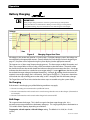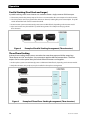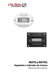
1
International Series GFX Inverter/Charger GFX1312E GFX1424E GFX1448E Operator’s Manual About OutBack Power Technologies OutBack Power Technologies is a leader in advanced energy conversion technology. Our products include true sine wave inverter/chargers, maximum power point tracking charge controllers, and system communication components, as well as circuit breakers, batteries, accessories, and assembled systems. Contact Information Telephone: Address: E-mail: Web Site: +1.360.435.6030 +1.360.618.4363 (Technical Support) +1.360.435.6019 (Fax) North America 5917 – 195th Street N.E., #7 Arlington, WA 98223 USA Address: Sales, Marketing, & Warranty 6115 – 192nd Street NE Arlington, WA 98223 USA [email protected] www.outbackpower.com Disclaimer UNLESS SPECIFICALLY AGREED TO IN WRITING, OUTBACK POWER TECHNOLOGIES (a) MAKES NO WARRANTY AS TO THE ACCURACY, SUFFICIENCY OR SUITABILITY OF ANY TECHNICAL OR OTHER INFORMATION PROVIDED IN ITS MANUALS OR OTHER DOCUMENTATION. (b) ASSUMES NO RESPONSIBILITY OR LIABILITY FOR LOSS OR DAMAGE, WHETHER DIRECT, INDIRECT, CONSEQUENTIAL OR INCIDENTAL, WHICH MIGHT ARISE OUT OF THE USE OF SUCH INFORMATION. THE USE OF ANY SUCH INFORMATION WILL BE ENTIRELY AT THE USER’S RISK. Warranty Summary OutBack Power Technologies warrants that the products it manufactures will be free from defects in materials and workmanship for a period of five (5) years subject to the conditions set forth in the warranty detail, found on page 55 of this manual. OutBack Power Technologies cannot be responsible for system failure, damages, or injury resulting from improper installation of their products. Notice of Copyright International Series GFX Operator’s Manual © February 2012 by OutBack Power Technologies. All Rights Reserved. Trademarks OutBack Power is a registered trademark of OutBack Power Technologies. Date and Revision February 2012, Revision B Part Number 900-0112-01-00 Rev B (for firmware revision 002.094.xxx) Important Safety Instructions READ AND SAVE THESE INSTRUCTIONS! This manual contains important safety instructions for the International Series GFX inverters. Read all instructions and cautionary markings on the inverter and on any accessories or additional equipment included in the installation. Failure to follow these instructions could result in severe shock or possible electrocution. Use extreme caution at all times to prevent accidents. Audience This manual is intended for anyone required to operate the GFX inverter. Operators must be familiar with all the safety regulations pertaining to operating this kind of equipment as dictated by local code. Operators must also have a complete understanding of this equipment’s features and functions. Do not use this product unless it has been installed by a qualified installer in accordance with the International Series GFX Installation Manual. Symbols Used WARNING: Hazard to Human Life This type of notation indicates that the hazard could be harmful to human life. CAUTION: Hazard to Equipment This type of notation indicates that the hazard may cause damage to the equipment. IMPORTANT: This type of notation indicates that the information provided is important to the installation, operation and/or maintenance of the equipment. Failure to follow the recommendations in such a notation could result in voiding the equipment warranty. General Safety WARNING: Limitations on Use This equipment is NOT intended for use with life support equipment or other medical equipment or devices. CAUTION: Equipment Damage Only use components or accessories recommended or sold by OutBack Power Technologies or its authorized agents. 900-0112-01-00 Rev B 1 Important Safety Instructions Definitions The following is a list of initials, terms, and definitions used in conjunction with this product. Table 1 Terms and Definitions Term Definition AC Alternating Current; refers to voltage produced by the inverter, utility grid, or generator AGS Advanced Generator Start AUX Inverter’s 12-volt auxiliary output CE Conformité Européenne; French for “European Conformity”; a marking on OutBack products indicating that they meet certain European Union requirements DC Direct Current; refers to voltage produced by the batteries or renewable source DVM Digital Voltmeter Grid-interactive, grid-intertie, grid-tie Utility grid power is available for use and the inverter is a model capable of returning (selling) electricity back to the utility grid HBX High Battery Transfer; a function of the remote system display IEEE Institute of Electrical and Electronics Engineers; refers to a series of standards and practices for the testing of electrical products LBCO Low Battery Cut-Out; set point at which the inverter shuts down due to low voltage LED Light-Emitting Diode; refers to indicators used by the inverter and the system display Off-grid Utility grid power is not available for use On-grid Utility grid power is available for use (does not imply grid-interactive capability) PV Photovoltaic RE Renewable Energy RTS Remote Temperature Sensor; accessory that measures battery temperature for charging System display Remote interface device (such as the MATE), used for monitoring, programming and communicating with the inverter; also called “remote system display” Utility grid The electrical service and infrastructure supported by the electrical or utility company; also called “mains”, “utility service”, or “grid” 2 900-0112-01-00 Rev B Table of Contents Important Safety Instructions ........................................................................1 Audience .................................................................................................................................................................................1 Symbols Used ........................................................................................................................................................................1 Definitions...............................................................................................................................................................................2 General Safety .......................................................................................................................................................................1 Introduction.................................................................................................7 Welcome to OutBack Power Technologies.................................................................................................................7 System Display and Controller ........................................................................................................................................8 Commissioning ............................................................................................9 Functional Test......................................................................................................................................................................9 Pre-startup Procedures ..................................................................................................................................................................9 Startup .................................................................................................................................................................................................9 Powering Down..............................................................................................................................................................................10 Adding New Devices.....................................................................................................................................................................10 Operation ..................................................................................................11 LED Indicators..................................................................................................................................................................... 11 Description of Functions ................................................................................................................................................ 13 Inverting............................................................................................................................................................................................13 Search ................................................................................................................................................................................................14 Input ...................................................................................................................................................................................................14 Generators........................................................................................................................................................................................16 Transfer..............................................................................................................................................................................................16 Input Support..................................................................................................................................................................................17 Battery Charging ............................................................................................................................................................................18 Equalization .....................................................................................................................................................................................22 Battery Temperature Compensation.......................................................................................................................................22 Selling ................................................................................................................................................................................................24 Multiple-Inverter Installations (Stacking)...............................................................................................................................25 Power Save Levels..........................................................................................................................................................................27 Auxiliary Terminals ........................................................................................................................................................................28 System Display-Based Functions................................................................................................................................. 30 Automatic Generator Start (AGS) .............................................................................................................................................30 High Battery Transfer (HBX)........................................................................................................................................................30 Grid Use Programming ................................................................................................................................................................30 Troubleshooting.........................................................................................31 Basic Troubleshooting..................................................................................................................................................... 31 Error Messages ................................................................................................................................................................... 37 Warning Messages............................................................................................................................................................ 38 Disconnect Messages ...................................................................................................................................................... 39 Selling or Charging Stopped......................................................................................................................................... 40 Specifications .............................................................................................43 900-0112-01-00 Rev B 3 Table of Contents Specifications for Model GFX1312E.............................................................................................................................43 Specifications for Model GFX1424E.............................................................................................................................44 Specifications for Model GFX1448E.............................................................................................................................45 Environmental Specifications ........................................................................................................................................46 Regulatory Specifications................................................................................................................................................46 Grid-Interactive Use ......................................................................................................................................................................46 Default Settings and Ranges..........................................................................................................................................47 Product Registration................................................................................... 53 Warranty ................................................................................................... 55 How to Arrange for Warranty Service .........................................................................................................................56 Contacting OutBack......................................................................................................................................................................56 Troubleshooting ............................................................................................................................................................................56 Return Material Authorization (RMA) .....................................................................................................................................56 Returning Product to OutBack..................................................................................................................................................57 Index......................................................................................................... 59 4 900-0112-01-00 Rev B Table of Contents List of Tables Table 1 Table 2 Table 3 Table 4 Table 5 Table 6 Table 7 Table 8 Table 9 Table 10 Table 11 Table 12 Table 13 Table 14 Table 15 Table 16 Table 17 Table 18 Table 19 Table 20 Table 21 Table 22 Terms and Definitions..................................................................................................................... 2 Battery LED Values..........................................................................................................................11 Status LED Quick Reference ........................................................................................................12 Basic Troubleshooting Steps ......................................................................................................31 Error Troubleshooting ...................................................................................................................37 Warning Troubleshooting............................................................................................................38 Disconnect Troubleshooting ......................................................................................................39 Stop Sell (and Charge) Reasons .................................................................................................40 Electrical Specifications (GFX1312E)........................................................................................43 Mechanical Specifications (GFX1312E) ...................................................................................43 Electrical Specifications (GFX1424E)........................................................................................44 Mechanical Specifications (GFX1424E) ...................................................................................44 Electrical Specifications (GFX1448E)........................................................................................45 Mechanical Specifications (GFX1448E) ...................................................................................45 Environmental Specifications for All Models........................................................................46 Interconnection Response to Voltage and Frequency .....................................................46 12-Volt Inverter Settings (MATE) ...............................................................................................47 24-Volt Inverter Settings (MATE) ...............................................................................................48 48-Volt Inverter Settings (MATE) ...............................................................................................49 12-Volt Inverter Settings (MATE3).............................................................................................50 24-Volt Inverter Settings (MATE3).............................................................................................51 48-Volt Inverter Settings (MATE3).............................................................................................52 List of Figures Figure 1 Figure 2 Figure 3 Figure 4 Figure 5 Figure 6 Figure 7 Figure 8 Figure 9 International Series GFX Inverter/Charger .............................................................................. 7 MATE3 and MATE System Display and Controller................................................................ 8 AC Wiring Compartment................................................................................................................ 9 LED Indicators...................................................................................................................................11 Charging Stages Over Time.........................................................................................................18 Repeated Charging Cycles...........................................................................................................21 OutBack HUB4 and MATE.............................................................................................................25 Example of Parallel Stacking Arrangement (Three Inverters) ........................................26 Example of Three-Phase Stacking Arrangement (Three Inverters) ..............................26 900-0112-01-00 Rev B 5 Introduction Welcome to OutBack Power Technologies Thank you for purchasing the OutBack International Series GFX Inverter/Charger. This product offers a complete power conversion system between batteries and AC power. It can provide backup power or complete off-grid service. ¾ Battery-to-AC inverting which delivers 230 Vac at 50 Hz ¾ AC-to-battery charging ¾ Rapid transfer between AC source and inverter output with minimal delay time ¾ Inverter load support for a small AC source ¾ 12-, 24-, and 48-volt inverters ¾ Wattages from 1.3 kVA to 1.4 kVA ¾ Stackable in parallel and three-phase configurations ¾ Uses energy from PV, wind, and other renewable resources. Use of OutBack FLEXmax charge controllers will optimize power production from PV sources. ¾ Grid-interactive capable ¾ CE compliant for off-grid use 2 pt./ flat head Figure 1 900-0112-01-00 Rev B International Series GFX Inverter/Charger 7 Introduction System Display and Controller The GFX inverters have no external controls. They can operate normally without an external control or interface. Basic modes and settings are pre-programmed at the factory. (See page 47 for default settings.) The MATE and MATE2 System Display and Controller (sold separately) are OutBack products designed to accommodate programming and monitoring of an OutBack power system. The MATE3 System Display and Controller (also sold separately) is an advanced system display that can interface with the GFX inverter. It has a simpler user interface and more options than the MATE or MATE2. It also has data logging and Web interface functions. Each system display provides the means to adjust the factory default settings to correctly match the installation where needed. It also provides the means to monitor system performance and troubleshoot fault or shutdown conditions. Once settings are modified, the system display can be removed from the installation. The settings are stored in the nonvolatile memory of the GFX inverter. However, it is highly recommended to include a system display as part of the system. This provides the means to monitor system performance and respond quickly should it be necessary to correct a fault or shutdown condition. The MATE3’s Configuration Wizard is capable of automatically configuring inverters to a series of preset values. This is often more efficient than attempting to manually program each setting in each inverter. Affected fields include system type, battery charging, and AC source configuration. (For more information, see the MATE3 Owner’s Manual). IMPORTANT: Some functions are not based in the inverter, but are part of the system display’s firmware. They will not function if the system display is removed. These functions are listed on page 30. For a detailed description of functions and programming, please see the manual for the system display. MATE3 Figure 2 8 MATE MATE3 and MATE System Display and Controller 900-0112-01-00 Rev B Commissioning Functional Test Pre-startup Procedures 1. 2. 3. 4. Ensure all DC and AC overcurrent devices are opened or turned off. Double-check all wiring connections. Inspect the work area to ensure tools or debris have not been left inside. Verify battery voltage using a digital voltmeter (DVM). Confirm the voltage is correct for the inverter model. Confirm the polarity. 5. Connect the system display (if present). CAUTION: Equipment Damage Incorrect battery polarity will damage the inverter. Excessive battery voltage also may damage the inverter. This damage is not covered by the warranty. Startup If steps are inapplicable, they can be omitted. However, it is highly recommended that all applicable steps be performed as below. If the results of a step do not match the description, see the Troubleshooting section on page 31. To start the system: 1. Close the main DC circuit breaker (or connect the fuse) from the battery bank to the inverter. Repeat for every inverter present. 2. Observe the LEDs in the AC wiring compartment. One of the three BATTERY LEDs should be illuminated — green, yellow, or red. Any of them are acceptable at this stage. (See page 11 for a description of the LEDs.) The INVERTER LED (green) may come on at this time. The fan will run briefly and the relay will click as a self-test. 3. The ERROR LED may flash briefly. If it remains illuminated or continues to flash during any step, proceed immediately to page 31 for troubleshooting. 4. Confirm that the system display is operational. (See the system display manual for a description of the menu items that appear on a correctly functioning display.) Continued on the next page... Figure 3 900-0112-01-00 Rev B AC Wiring Compartment 9 Commissioning continued from previous page.... 5. If the INVERTER LED (green) is not illuminated, turn on the inverter using the system display or external switch. 6. Check the STATUS LEDs. Confirm that the INVERTER LED (green) is illuminated. 7. Using a DVM, verify 230 Vac between the AC HOT OUT and AC NEUTRAL OUT terminals. Do not turn on any AC circuit breakers at this time. 8. Using the system display, perform all programming for stacking, battery charging, AC current, generator starting, and any other functions. Refer to the Description of Functions section beginning on page 13. Also refer to the system display manual and any other literature as needed. After programming is completed, perform the following steps: 1. If other inverters are on the system, use a DVM to verify correct voltage from AC HOT OUT on one inverter to the next. Parallel-stacked inverters should collectively read 0 Vac (although individually they should still read 230 Vac). Three-phase inverters should collectively read 400 Vac. 2. Close the AC output circuit breakers. If AC Bypass circuit breakers are present, place them in the normal (non-Bypass) position. Do not connect an AC input source or close any AC input circuits. 3. Use a DVM to verify correct voltage at the AC load panel. 4. Connect a small AC load and test for proper functionality. 5. Close the AC input circuit breakers and connect an AC source. 6. Check the STATUS LEDs. The AC IN LED (yellow) should flash. The INVERTER LED will remain illuminated for a short time. When the AC IN LED stays illuminated, the INVERTER LED should go dark. This means the inverter is no longer drawing on batteries, but is using the AC source. 7. If the battery charger has been enabled, confirm that it is charging by using the system display. The inverter will perform a full battery charge when first powered up. This may take several hours. If restarted after a temporary shutdown, the inverter may skip most or all of the charging cycle. 8. Test any other functions which have been enabled, such as generator start, selling, or search mode. International Series GFX inverters have a minimum one-minute delay before selling will begin. 9. Compare the DVM’s readings with the system display meter readings. If necessary, the system display’s readings can be calibrated to match the DVM more accurately. AC input voltage, AC output voltage, and battery voltage can be calibrated. Powering Down If steps are inapplicable, they can be omitted. However, it is highly recommended that all applicable steps be performed in the following order. To Power Down the System: 1. 2. 3. 4. Turn off all load circuits and AC input sources. Turn off all renewable energy circuits. Turn each inverter OFF using the system display or external switch. Turn off the main DC overcurrent device for each inverter. Adding New Devices When adding new devices to the system, first power down the system according to the preceding instructions. After adding new devices, perform another functional test, including programming. 10 900-0112-01-00 Rev B Operation LED Indicators AUX LED (see page 27) BATTERY LEDs STATUS LEDs Figure 4 LED Indicators BATTERY LEDS The battery LEDs show the approximate battery state. (See IMPORTANT note below.) The BATTERY LEDs are independent of STATUS LEDs. Any STATUS LED could accompany any BATTERY LED based on certain conditions. Common combinations are noted. ¾ A GREEN LED means the batteries have an adequate charge at that time. It does not always mean they are full. May be accompanied by a YELLOW STATUS LED when an AC source is charging. ¾ A YELLOW LED means the batteries are somewhat discharged. ¾ A RED LED means the batteries are greatly discharged and may require attention. May be accompanied by a RED STATUS LED to indicate a Low Battery ERROR. Table 2 Battery LED Values Color 12 Vdc Unit 24 Vdc Unit, ± 0.2 Vdc 48 Vdc Unit, ± 0.4 Vdc Battery Status GREEN 12.5 Vdc or higher 25.0 Vdc or higher 50.0 Vdc or higher ACCEPTABLE YELLOW 11.5 to 12.4 Vdc 23.0 to 24.8 Vdc 46.0 to 49.6 Vdc MARGINAL RED 11.4 Vdc or lower 22.8 Vdc or lower 45.6 Vdc or lower LOW NOTES: ¾ Gaps in the table (higher-voltage units) are due to the resolution of the inverter’s DC meter. ¾ These voltage settings are not the same as the Low Battery Cut-Out (LBCO) set point. (See pages 13 and 37.) The Battery LED settings cannot be changed. ¾ Voltages higher than shown in the GREEN row usually means that the batteries are charging. IMPORTANT: Battery voltage does not always indicate an accurate state of charge. It is accurate if batteries have been at rest for several hours at room temperature (25°C or 77°F, or as specified by the battery manufacturer). If they have any loads, a charging source, or are at another temperature, their voltage may not reflect their true state. The OutBack FLEXnet DC is a battery monitor which can provide accurate measurements. 900-0112-01-00 Rev B 11 Operation STATUS LEDS GREEN ¾ Solid: The inverter is ON and providing power. If accompanied by solid yellow LED, unit is selling power to the utility grid. (See page 24 for a description of the Sell function.) ¾ Flashing: The inverter has been turned ON but is idle. May be accompanied by the yellow LED. If not accompanied by the yellow LED, the unit is in inverting mode and is idle due to lack of demand. This can be because the unit is in Search mode. (See page 14 for a description of Search.) ¾ Off: Unit is OFF. It is not waiting to provide power. Any power present is from another source such as the utility grid or generator. (See Startup on page 9, or the system display manual, to turn the unit ON.) The unit may also be a slave that is in Power Save mode. If so, the master inverter may still be providing power to the system. (See page 27 for a description of Power Save.) YELLOW ¾ Solid: The AC source is connected and providing power. Unit may or may not be charging the batteries, depending on settings. May be accompanied by green LED. ¾ Flashing: The AC source is present but has not been accepted. If flashing continues, the unit is refusing the source. This can occur for the following reasons. ∼ The AC source may have quality issues. External diagnosis may be required. (See page 15 for a description of input criteria. See the system display manual for diagnosis using the meter displays.) ∼ In the system display, the AC Input menu is set to DROP. (See the system display manual for a description of the AC IN or AC INPUT hot key.) ∼ In the system display, the High Battery Transfer (HBX) feature or the Grid Use feature intentionally disconnected the inverter. (See the system display manual for a description of these modes.) ¾ Off: No AC source is detected. If a source is supposed to be present, confirm the voltage between AC HOT IN and AC NEUTRAL IN terminals. RED ¾ Solid: ERROR. Unit has shut down due to a critical problem which may be internal or external to the inverter. This LED is accompanied by an error message in the system display. See page 37 for a description of error messages. ¾ Flashing: WARNING. Unit has detected a non-critical problem but has not yet shut down. A warning does not always lead to a shutdown — if it does, it becomes an error. This LED is accompanied by a warning message in the system display. See page 37 for a description of warning messages. ¾ Off: No problems are detected. Table 3 Color GREEN State Solid GREEN Flashing GREEN Off Solid YELLOW YELLOW Flashing YELLOW Off Solid RED RED Flashing RED Off 12 Status LED Quick Reference Inverter State Notes Inverter is ON and providing power. Inverter is ON but standing by. Inverter is not providing power. If accompanied by YELLOW LED, unit is selling. Unit may be in Search mode. Unit is either OFF or has been replaced by an AC source (see next item). Unit may or may not be charging batteries, depending on settings. Unit may be programmed not to accept the source, or the source may have quality issues. If source is present, check AC input. To see error messages, see the system display manual. To see warning messages, see the system display manual. AC source connected and providing power. AC source present but not yet accepted. No AC source is detected. ERROR. Unit has shut down. See Troubleshooting. WARNING. Unit detected a problem but has not yet shut down. See Troubleshooting. No problems detected. 900-0112-01-00 Rev B Operation Description of Functions All items identified as settable or adjustable have set points which can be accessed using the remote system display. (See the system display manual for instructions on locating these set points.) The default settings and ranges of adjustment are listed near the end of this book, beginning on page 47. Each function is accompanied by a symbol representing the inverter and that function: DC TRANSFER AC IN AC OUT These items represent the input from the AC source, the output to the AC loads, DC functions (inverting, charging, etc), and the transfer relay. Arrows on each symbol represent current flow. The symbols for each function may have other features depending on the function. Inverting A GFX inverter uses a transformer and a high-frequency H-Bridge FET design to convert DC voltage from batteries into AC voltage that is usable by AC appliances. It will continue to do this as long as the batteries have sufficient energy. The batteries can be supplied or recharged from other sources, such as solar, wind, or hydroelectric power. The inverter requires batteries to operate. Other sources may not maintain DC voltages that are consistent enough for the inverter to operate reliably. CAUTION: Equipment Damage Do not substitute other DC sources in place of the batteries. High or irregular voltages may damage the inverter. It is normal to use other DC sources in conjunction with the batteries and the inverter, but not in place of the batteries. Certain features will affect the inverter’s operation. These features only operate when the inverter is generating AC power on its own. They do not function when the inverter is supplied by an AC source. ¾ Low Battery Cut-Out (LBCO): This function prevents the inverter from draining the batteries completely. When the DC voltage drops below a specified level for 5 minutes, the inverter will stop functioning. The system display will give a Low Battery Voltage or Low Battery V error. This is one of the Error messages described on page 37. This function is intended to protect both the batteries and the inverter’s output. (Continuing to invert on a low DC voltage may produce a distorted waveform.) This item is adjustable. ¾ Low Battery Cut-In (LBCI): The recovery point from Low Battery Cut-Out. When the voltage rises above this point for 10 minutes, the Low Battery error will clear and the inverter will function again. This is adjustable. ∼ Connecting an AC source to charge the batteries will also clear a Low Battery error. ¾ AC Output Voltage: The inverter’s AC output can be turned up or down by a certain amount to adjust for conditions. This item is adjustable. ¾ The inverter is also controlled by a high battery cut-out function. If the DC voltage rises above a certain level, the inverter will immediately stop functioning. The system display will give a High Battery Voltage or High Battery V error. This is one of the Error messages displayed on page 37. (If the voltage drops below this point, the inverter automatically recovers.) ∼ For a 12-volt inverter, this voltage is 17 volts. ∼ For a 24-volt inverter, the voltage is 34 volts ∼ For a 48-volt inverter, the voltage is 68 volts. The high battery cut-out voltages cannot be changed. 900-0112-01-00 Rev B This function is intended to protect the inverter’s output and loads. Continuing to invert on a high DC voltage may produce a distorted waveform. Note that the high battery cut-out does not alleviate the high battery condition itself; it is an external condition. 13 Operation Search An automated search circuit is available to minimize the power draw when no loads are present. When enabled, the inverter does not always deliver full output. The output is reduced to brief pulses with a delay between them. These pulses are sent down the output lines to see if a resistance is present. In effect, the pulses “search” for a load. If one is detected, the inverter’s output increases to full voltage so that it can power the load. When the load is turned off, the inverter “goes to sleep” and begins searching again. The sensitivity of Search mode is in increments of approximately 0.1 Aac. The default is 6 increments, or 0.6 Aac. A load which draws this amount or greater will “wake up” the inverter. NOTE: Due to changing load characteristics, these increments are only approximate and may not function exactly as listed. The pulse duration and the delay both have a time period that is measured in AC cycles. These two items and the load detection threshold are adjustable. ¾ Search mode can save a considerable amount of power, particularly in smaller systems with intermittent use. ¾ Search mode may not be useful in larger systems with loads that require continuous power (e.g., clocks, answering machines, fax machines). Search mode may cause nuisance shutdowns, or it may sleep so rarely that there is no benefit. ¾ Some devices may not be easily detectable by Search mode. Input When the GFX inverter input terminals are connected to a stable AC source, the inverter will synchronize itself with that source and use it as the primary source of AC power. (See “AC Source Acceptance” on page 15.) In this situation, the transfer relay will engage, linking the AC source directly with the inverter’s output. It can also use the source to charge batteries. (See “Transfer” on page 16 and “Battery Charging” on page 18.) ¾ Two sets of input criteria are available, one for the utility grid and one for a generator. Only one source can be selected at a time. In the MATE system display, the source is selected using the ac transfer control menu. In the MATE3 system display, it is selected using either the Inverter Input Select or the AC Input and Current Limit menus. See the system display manual for more information. (For other aspects of input selection, see the items below. Also see AC Current Settings on page 15.) Both grid and generator criteria are adjustable. ¾ The grid-interactive function can sell power using the input connection. (See the section entitled “Selling” on page 24.) In the MATE, this function only operates if grid is selected in the ac transfer control menu. It does not function if gen is selected. ¾ The Input Support feature can use battery power to assist a smaller AC source. (See the section entitled “Input Support” on page 17.) ¾ There are a number of considerations when selecting the type and size of an AC generator. (See the section entitled “Generators” on page 16.) ¾ The AC input current is used to power both loads and battery charging. The total should not exceed the size of the AC overcurrent device or AC source. These devices should be sized appropriately during planning. ¾ The loads powered by the inverter must not exceed the size of the inverter’s transfer relay. (See the section entitled “Transfer” on page 16.) CAUTION: Equipment Damage Current draw in excess of the inverter’s transfer relay rating can damage the transfer relay. This damage is not covered by warranty. 14 900-0112-01-00 Rev B Operation AC Current Settings The AC current settings control the amount of current that the inverter draws from the source(s). The amount of current is controlled by the grid or generator limit settings. These settings should be adjusted to match the size of the input circuit breaker or input conductor. In the system display, if the source is set to grid, the inverter uses the grid settings. If the source is set to gen, the inverter uses the generator settings. ¾ This is intended to protect a generator or source that may not be large enough to supply enough current for both charging and loads. If the combined charging and loads exceed this setting, the inverter will reduce its charge rate and give priority to the loads. If the loads exceed this number on their own, the charge rate will be reduced to zero. The inverter is capable of supporting the source with power from the batteries. See the section entitled “Input Support” on page 17. ¾ If multiple parallel inverters are installed with an AC source of limited amperage, the total combined amperage settings for all units must be less than the AC input circuit. The Configuration Wizard in the MATE3 can perform this calculation. However, the inverters do not perform this calculation. If the MATE3 or the Configuration Wizard are not used, it may be necessary to divide the input size by the number of inverters and assign an equal part of the amperage to each port. AC Source Acceptance The input source must meet the following specifications to be accepted: ¾ 230 Vac, ± 22 Vac (default setting), and ¾ 50 Hz, ± 5 Hz When these conditions are met, the inverter will close its transfer relay and accept the input source. This occurs after a delay which is specified below. If the conditions are not met, the inverter will not accept the source. If it was previously accepted and then rejected, the inverter will open the relay and return to inverting power from the batteries. ¾ If the source is set to grid, there is a connection delay of approximately 15 seconds. This time is not adjustable. ¾ If the source is set to gen, there is a connection delay with a default setting of 0.5 minutes. This is intended as a generator warmup period. This item is adjustable. NOTES: Several items, external to the inverter, may prevent the inverter from accepting AC power even if electrical conditions are met. One is the high-battery transfer (HBX) mode, which is operated by the system display. (See page 30 and the system display manual.) Another is the system display’s AC IN or AC INPUT hot key, which can turn off the input to all inverters. (See the system display manual.) The inverter has additional criteria that control whether it sells power. The inverter may accept AC power but refuse to sell if the acceptance criteria are met, but the grid-interactive criteria are not. (See the section entitled “Selling” on page 24.) 900-0112-01-00 Rev B 15 Operation Generators A generator should be sized to provide enough power for both loads and battery charging. ¾ The generator needs a single circuit which is sized to provide current to all inverters on a given phase or leg. ¾ It is usually recommended that the generator be sized at twice the wattage of the inverter system. Many generators may not be able to maintain AC voltage or frequency for long periods of time if they are loaded more than 80% of rated capacity. ¾ Using the MATE system display, it is recommended to set the AC source to gen when connecting a generator. If the setting is left on grid, the inverter’s internal settings will still be set for utility-grade power. Unless the generator delivers extremely high-quality power, it might not be accepted. (Alternately, the inverter might accept the generator and attempt to sell power back to it.) Changing to gen will remove the requirements for high-grade power and will prevent selling. The generator is required to have a stable output before its power is accepted by the inverter. Some generators with less stable or uneven outputs may not be accepted. When using capacitor-excited generators or self-excited induction generators, there can be side effects while using the Input Support feature (see page 17). These generators do not always deliver full output when operating in parallel with another source of power, such as the Input Support feature. The inverter’s battery charger may work erratically or at a low charge rate. It may be necessary to disable the Input Support feature. Consult the generator manufacturer if necessary. Transfer The inverter uses a transfer relay to alternate between the states of inverting and of accepting an AC source. Until the relay energizes, the AC HOT IN and AC HOT OUT terminals are electrically isolated from each other; when it closes, they become electrically common. When the relay changes states, the physical transfer delay is approximately 12 milliseconds. ¾ The AC NEUTRAL IN and AC NEUTRAL OUT terminals are electrically common regardless of the state of the relay. ¾ The relay contacts are limited to 30 amps per phase or leg. The continuous loads on that output should never exceed this number. When connected to an AC source, the inverter cannot limit the load current. An overload condition is possible. CAUTION: Equipment Damage Current draw in excess of the inverter’s transfer relay rating can damage the transfer relay. This damage is not covered by warranty. The inverter does not filter or clean up the power from the AC source. The voltage and power quality received by the output loads is the same as that of the source. If the voltage or quality do not meet the inverter’s input limits (see page 15), it will disconnect and return to the inverting mode. ¾ If the AC source meets the inverter’s requirements but is irregular, any fluctuations will be transferred to the loads. If the loads are sensitive, it may be necessary to improve the quality of the AC source. ¾ For a smoother transition, it may be useful to raise the inverter’s lower acceptance limit. The default setting is 208 Vac. A higher setting will cause the inverter to transfer sooner in the event of a quality problem. In a stacked system, slaves are ordered to transfer at the same time as the master. If a slave does not sense an AC source, it will suffer a Phase Loss Error (see page 37). The slave will continue inverting. 16 900-0112-01-00 Rev B Operation Input Support A system display is required to control this function. When this function is enabled, the inverter limits the current draw from an AC source, augmenting it with additional current from the batteries when necessary. This helps prevent overloading a small AC circuit or generator during short-term use. Initially the AC source current is used for both loads and battery charging. In the MATE system display, the ac1/grid limit or ac2/gen limit settings control the maximum AC draw. In the MATE3 system display, these settings are made by the Grid Input AC Limit and Gen Input AC Limit menu items. If the AC draw exceeds the setting, the inverter reduces its charge rate to give priority to the loads. ¾ The charge rate will be reduced as much as necessary to support the loads. If the loads equal the amperage setting, the charge rate will be zero. ¾ If the AC loads exceed the amperage setting, the charger will begin operating in reverse. It will take power from the batteries and use it to support the incoming AC current. IMPORTANT: If the AC loads exceed the amperage limit setting, the inverter will drain the batteries. If the loads are sustained, the batteries may discharge to the point of Low Battery Cut-Out and the inverter may shut down with a Low Battery error. (See pages 13 and 37.) To prevent the loss of backup power, load use should be planned accordingly. In the MATE system display, this feature is activated by the ac2/gen support menu item, located in the ADVANCED menus. In the MATE3 system display, it is activated by the Input Support menu item, located in the AC Input and Current Limit menu. (See the system display manual.) ¾ Although the menu is titled “ac2/gen support” in the MATE, it functions equally well whether the AC source is a generator or the utility grid. ¾ Choose between generator or grid criteria using the MATE’s ac transfer control menu. The default is grid. The <GRID> and <GEN> soft keys will toggle between these respective options. ¾ The default selection is on. It can be switched off using the <OFF> soft key. The MATE’s ac transfer control menu must be selected to gen in order to do this. In current models, if ac transfer control is set to grid, the support feature cannot be disabled. 900-0112-01-00 Rev B 17 Operation Battery Charging IMPORTANT: Battery charger settings need to be correct for a given battery type. Always follow battery manufacturer recommendations. Making incorrect settings, or leaving them at factory default settings, may cause the batteries to be undercharged or overcharged. Voltage Absorption Set Point Absorption Float Set Point Float Timer Sell RE Set Point Sell RE Silent No Charge Sell RE Float Refloat Set Point Silent Bulk Time Figure 5 Charging Stages Over Time All voltages in this section are given for a 12-volt system. For higher-voltage systems, the voltage can be multiplied by the appropriate amount. (Factory defaults for each voltage are shown beginning on page 47.) Set points can be adjusted using the system display (see the appropriate manual). The inverter uses a “three-stage” battery charging process. The three stages are Bulk, Absorption, and Float. These stages follow a series of steps, which are marked on the chart above. The points where the dark line intersects the vertical dotted line indicate a change from one step to the next. A circle indicates that the inverter has switched to a new target voltage. A square indicates that the inverter has reached the target voltage (a horizontal dotted line). A triangle indicates that the inverter has acquired a new target voltage, but is still inactive. (See Figure 6 on page 21.) The process shown here also includes the step of selling power to the utility, as this is integrally tied with the battery charger. The Target Points and Time Limits cited under various steps are settable using the system display. No Charging If the inverter is not charging, any of the following conditions may apply: ¾ The unit is inverting or not connected to a qualified AC source. ¾ The unit is connected to an AC source but is in a mode or stage that does not use the charger. (Silent mode is one example.) ¾ The unit is connected to an AC source but the charger has been turned off. Bulk Stage This stage activates the charger. This is the first stage in the three-stage charge cycle. It is a constant-current stage which drives the battery voltage up. This stage typically leaves the batteries at 75% to 90% of their capacity, depending on conditions. Target point: absorb setpoint or Absorb Voltage setting. The default is 14.4 Vdc (in a 12-volt system). 18 900-0112-01-00 Rev B Operation The initial DC current is the maximum current the charger can deliver. It will begin at the charger’s specified maximum, but will gradually decrease as the voltage increases. This is a tradeoff in wattage and is normal for the charger. Absorption Stage This is the second stage of charging. It is a constant-voltage stage. Current varies as needed to maintain the voltage, but will typically decrease to a very low number over time. This “tops off the tank”, leaving the batteries at essentially 100% of capacity. Target point: absorb setpoint or Absorb Voltage setting. Time limit: absorb time limit or Absorb Time setting. This timer counts down from the inception of the Absorption stage until it reaches zero. The timer can be viewed. (See the system display manual.) For multiple inverters only: The charging of multiple stacked inverters is synchronized and is governed by the master. When the master inverter reaches the end of Absorption (and other stages), the slaves will exit Absorption as well, even if their timers have not expired. The remaining time for the slaves will be retained in the timer for each inverter. The Absorption timer does not reset to zero when AC power is disconnected or reconnected. It only resets to zero if it runs out, or if an external STOP BULK command is sent. The rest of the time, it retains any remaining time. It adds more time to the Absorption period whenever the batteries fall below a certain voltage. (See page 21 for more information on how the timer works.) If the voltage exceeds the Absorption voltage setting (usually due to another charging source), the inverter(s) can sell current to the loads (or the source) in an effort to bring the voltage down to the set point. This will reduce the inverter’s draw from the AC source. Sell This is not a charging stage and is only used once the batteries are recharged. Sell is a constant-voltage mode of operation. The inverter cannot import current to charge the batteries to this value, but it can export any excess current to hold them at a constant voltage. (Usually excess current comes into the batteries from a PV array, wind turbine, or similar renewable source.) Target point: sell re volts or Sell Voltage setting. The default setting is 13.0 Vdc (in a 12-volt system). This setting is typically lower than the Float voltage setting. Although the batteries are not discharged, they are maintained at a somewhat lower voltage so that the maximum amount of power can be exported. Excess power is sent first to any loads on the inverter’s output, in what is known as “zeroing”. If the exported power exceeds the loads, the remainder is sold back to the utility grid, using the inverter’s AC input terminals. The unit will maintain this activity for as long as excess power is available. If excess power is not available, the battery voltage will drop below the Sell voltage and the unit will leave this stage. See page 24 for more notes on the Sell function. 900-0112-01-00 Rev B 19 Operation Silent This is not a charging stage, but a quiescent period between stages. The inverter remains on the AC source, but the charger is inactive. It enters this condition upon completing the Absorption stage, or when there is not enough energy to sustain selling. The term “Silent” is also used in the context of stacking inverters and Power Save levels. See page 27. In Silent, the batteries are not in significant use by the inverter, but they are also not being charged. The battery voltage will naturally decrease when not maintained by another means such as a renewable source. Target point: refloat setpoint or Re-Float Voltage setting, which activates the charger again. The default setting is 12.5 Vdc (in a 12-volt system). NOTE: If the MATE’s ac transfer control menu is set to gen, the charger skips both Sell and Silent, and proceeds directly to Float stage. The same is true if the MATE3’s charger control menu is set to on. (It will remain in Float until a new charge cycle is required, possibly through loss of AC power.) If ac transfer control is set to grid (or if charger control is set to off), the charger goes through Silent as noted and proceeds to Float only when the batteries drop to the Refloat voltage level. (See pages 14 and 15 for more information on this function.) Float Stage This is the third stage of charging. It is a constant-voltage stage. Current varies as needed to maintain the voltage, but typically drops to a low number. This stage offsets the batteries’ tendency to self-discharge (as well as the draw of any other DC loads), and maintains them at 100% of capacity. Target point: float setpoint or Float Voltage setting. The default setting is 13.6 Vdc (in a 12-volt system). Time limit: float time period or Float Time setting. If the voltage exceeds the Float voltage setting (usually due to another charging source), the inverter can sell current to the loads (or the source) in an effort to bring the voltage down to the set point. This will reduce the inverter’s draw from the AC source. Float Timer This is part of Float stage and is not a separate stage of charging. On the chart, it is marked as a separate step to note that the timer only begins running upon reaching the Float set point. It does not begin running at the beginning of Float stage. (The Float timer is reset to its maximum amount whenever the batteries drop to the Refloat voltage.) Repeated Silent The unit re-enters the Silent mode as it did on page 20. The unit remains on the AC source, but the charger is inactive. Target point: refloat setpoint or Re-Float Voltage setting, which activates the charger again. The default setting is 12.5 Vdc (in a 12-volt system). The unit will continue cycling between Float and Silent for as long as the AC source is present. However, if excess DC power is available and the batteries rise above the Sell RE set point, the unit can re-enter Sell and begin selling the excess as described above. The unit can only re-enter Sell when none of the timers are active. If any of the timers have accumulated time while in Silent, the unit will enter the highest stage with accumulated time and proceed from that point. 20 900-0112-01-00 Rev B Operation Voltage Absorption Absorption Set Point Absorption Float Set Point Sell RE Set Point Sell RE Sell RE Refloat Set Point Rebulk Point AC Loss No Charge Silent Float Float Timer Bulk Bulk Time Figure 6 Repeated Charging Cycles New Charging Cycle If the AC source is lost or disconnected, the unit will return to inverting mode if enabled. The battery voltage will begin to decrease due to loads or natural loss. When the AC source is restored, the inverter will return to the charging cycle. If the batteries drop below the Rebulk voltage (see below), the inverter will restart the cycle, beginning at Bulk stage. (See the triangle symbol in Figure 6.) If the batteries do not drop below Rebulk, the charger will not enter the Bulk stage and will return to its previous stage. New Absorption Stage When entering the second stage, Absorption, the charger will not necessarily run through its full duration. The timer will count down whatever time remains from the previous cycle, or whatever time it has accumulated since then. Absorption Timer The Absorption timer does not reset to its maximum like the Float timer does. Instead, the timer counts upward (gaining time) whenever the battery voltage drops below the Rebulk point. This means that the Absorption period may not always be the same, depending on how much time it has acquired. In a 12-volt system, the Rebulk voltage is 12.2 Vdc. (All voltages in this section are given for a 12-volt system.) This is a fixed setting and cannot be changed. For as long as the inverter remains below this voltage, the Absorption timer will gain an equal amount of time. This dictates the duration of the Absorption stage. Note that in Figure 6 the duration of time spent below the Rebulk voltage is the same as the subsequent Absorption period (as shown by the small arrows). If the battery voltage drops below 12.0 Vdc (in a 12-volt system), the timer increments (counts upward) at double the normal rate. For example, if the batteries spent 8 minutes below this voltage, 16 minutes would be added to the Absorption timer. Similarly, if the battery voltage drops below 11.8 Vdc (in a 12-volt system), the timer increments at quadruple the normal rate. The Absorption timer continues this behavior even if the charger is still on. For example, if the charger is in Float stage and there is a significant battery drain, the charger may not be able to maintain the batteries at the Float voltage. Once the batteries fall below the Rebulk point, the Absorption timer will begin accumulating time. (However, the accumulation will be minor, as this will also cause the charger to re-enter the Bulk stage.) The timer will stop incrementing when it reaches the absorb time limit or Absorb Time setting. This is the maximum duration of the Absorption stage. This means that regardless of the voltage, the timer 900-0112-01-00 Rev B 21 Operation will always run for the full Absorption period if the batteries dropped below the appropriate voltage for that amount of time. If significant battery drain caused them to drop below the set points for doubling or quadrupling the rate, it may run for the full Absorption period even after a lesser amount of time. The rest of the charging stages will proceed as described on the previous few pages. Equalization Equalization is a controlled overcharge that is part of regular battery maintenance. Equalization brings the batteries to a much higher voltage than usual and maintains this high voltage for a period of time. This has the result of removing inert compounds from the battery plates and reducing stratification in the electrolyte. This process must be started manually using the system display. The inverter cannot be programmed for automatic battery equalization. This is a safety measure. Equalization follows the same pattern as standard three-stage charging, as shown in Figure 5. However, instead of the Absorption voltage set points, it is controlled by the equalize set point or Equalize Voltage settings in the system display. The time is controlled by the equalize time period or Equalize Time setting. Equalization is normally performed only on flooded lead-acid batteries. The schedule for equalization varies with battery use and type, but it is usually performed every few months. If performed correctly, this process can extend battery life by a considerable amount. Equalization is not normally performed on nickel-technology batteries or any sort of sealed battery. CAUTION: Battery Damage ¾ Do not equalize any sealed battery types (VRLA, AGM, Gel, or other) unless approved by the manufacturer. Some batteries may suffer severe damage from equalization. ¾ Contact the battery manufacturer for recommendations on equalization voltage, duration, schedule, and/or advisability. Always follow manufacturer recommendations for equalization. Battery Temperature Compensation Battery performance will change when the temperature varies above or below room temperature (77°F or 25°C). Temperature compensation is a process that adjusts battery charging to correct for these changes. When a battery is cooler than room temperature, its internal resistance goes up and the voltage changes more quickly. This makes it easier for the charger to reach its voltage set points. However, while accomplishing this process, it will not deliver all the current that the battery requires. As a result, the battery will tend to be undercharged. Conversely, when a battery is warmer than room temperature, its internal resistance goes down and the voltage changes more slowly. This makes it harder for the charger to reach its voltage set points. It will continue to deliver energy as time passes until the charging set points are reached. However, this tends to be far more than the battery requires, meaning it will tend to be overcharged. 22 900-0112-01-00 Rev B Operation The inverter, when equipped with the Remote Temperature Sensor (RTS), will compensate for changes in temperature. The RTS is attached to a single battery near the center of the bank, to achieve a representative temperature. If installed in a multiple-inverter system, only a single RTS is necessary. It must plug into the master inverter and will control the charging of all slaves and all charge controllers. (See the International Series GFX Installation Manual to locate the RTS port.) This process is automatic. When charging, an inverter system with an RTS will increase or decrease the charge voltage by 5 mV per degree Celsius per battery cell. This setting affects the Absorption, Float, and Equalization set points. The Sell RE and Refloat set points are not temperature compensated. The Equalization set points are not compensated in OutBack charge controllers. ¾ In a 12 Vdc system (6 cells, 2 volts each), this means 0.03 volts per degree Celsius above or below 25°C. Maximum compensation is ± 0.6 Vdc. ¾ In a 24 Vdc system (12 cells, 2 volts each), this means 0.06 volts per degree Celsius above or below 25°C. Maximum compensation is ± 1.2 Vdc. ¾ In a 48 Vdc system (24 cells, 2 volts each), this means 0.12 volts per degree Celsius above or below 25°C. Maximum compensation is ± 2.4 Vdc. Examples: ¾ A 12 Vdc system with batteries at 10°C will compensate its charging to 0.45 Vdc higher than the set points. ¾ A 24 Vdc system with batteries at 35°C will compensate its charging to 0.6 Vdc lower than the set points. ¾ A 48 Vdc system with batteries at 15°C will compensate its charging to 1.2 Vdc higher than the set points. 900-0112-01-00 Rev B 23 Operation Selling IMPORTANT: Selling power to the utility company requires the authorization of the local electric jurisdiction. How the local utility company handles this will depend on their policies on this issue. Some may pay for power sold; others may issue credit. Some policies may prohibit the use of this mode. Please check with the utility company and obtain their permission before using this mode. The GFX inverters are grid-interactive. This means that in addition to using power from the utility grid for charging and loads, these models can also convert excess battery power and sell it to the utility grid. This is known as the “grid-tie” or “Sell” feature. Excess battery power usually comes from renewable energy sources, such as PV arrays, hydroelectric turbines, and wind turbines. ¾ The operation of the Sell feature is referenced heavily in the Battery Charging section, as it is integrally tied with the battery charger. In fact, selling is occasionally referred to as “charging in reverse”. Where the charger draws power from the AC input and puts it into the batteries, the Sell feature removes power from the batteries (or the DC system) and returns it to the AC input. ¾ The Sell feature can only operate while the utility grid power is stable and within certain limits. If the AC voltage or frequency vary outside these limits, the inverter will stop selling. It may not disconnect from the utility grid. If the inverter stops selling, the system display will show the reason (page 40 has a list of reasons). ¾ The inverter’s grid-interactive limits are specified on page 46. The AC source acceptance limits are specified on page 15. These numbers are often not the same. ¾ Once the AC voltage and frequency become acceptable, the inverter has a minimum one-minute delay before selling will begin. Upon initial connection to the utility grid, the inverter may be required to perform a full battery charge. This may delay the operation of the sell feature. ¾ In the MATE system display, the key set point is sell re volts. In the MATE3, it is Sell Voltage. (See the system display manual to change this set point.) When the charger enters the Sell stage (see pages 18 and 19), it uses sell re volts or Sell Voltage as a reference point. When a renewable source of energy raises the voltage above this point, the inverter exports power to bring the voltage back down or prevent it from rising further. The Sell feature only functions when excess DC (renewable) power is available. ∼ ∼ The inverter cannot import AC power to raise the voltage to the sell re volts or Sell Voltage set point. The Sell feature can use other set points than sell re volts or Sell Voltage. If the charger is in a different stage, such as Absorption or Float, it uses the Absorption or Float voltage as reference points. As long as the renewable energy exceeds the voltage for that stage, it sells exactly the same as noted above. ¾ When power is returned to the utility grid, it is possible to completely reverse the utility meter. The net result would be to sell power to the utility company. However, this depends on whether there are other loads in the system. Loads on the main panel (not on the inverter’s output) may consume this power as fast as it is generated, preventing the meter from running backwards. In this case, the result of selling would be to reduce the consumption of AC power, not reverse it. ¾ The maximum amount of power an inverter can sell is not equal to its specified output wattage. It can exceed the specified wattage under some conditions, usually temporarily. (Its maximum output is 30 amps.) ∼ ∼ 24 However, output will vary with inverter temperature, battery type, and other conditions. The inverter should not be expected to sell 100% of its specified output wattage continuously. Even though it may be able to do so, this may leave it too hot to perform other functions (such as starting heavy loads if they are needed during a utility outage). A good guideline is that the renewable source should be sized to continuously deliver no more than 85% of the inverter’s specified wattage (per inverter, in a multi-inverter system). This recommendation is specifically for the inverter’s Sell feature. In some cases, the source may be sized larger to account for environmental conditions or the presence of DC loads. This depends on individual site requirements. 900-0112-01-00 Rev B Operation Multiple-Inverter Installations (Stacking) Multiple inverters in a single system can support larger loads than a single inverter can handle. Installing inverters in this configuration is called “stacking”. Stacking inverters does not refer to physically placing one on top of another. It refers to how they are wired within the system and then programmed to coordinate activity. Stacking allows all units to work together as one system. Each inverter is programmed to power an individual phase of the system and to operate at certain times. This order is assigned using a system display, such as the OutBack MATE or MATE3. (Stacking the GFX inverters requires a MATE with firmware revision 4.1.6 or above.) Examples of stacking configurations include “parallel” and “three-phase” configurations. Stacking requires an OutBack HUB product, as well as a system display. A system of four or fewer units may use the HUB4. Systems of up to ten units require the HUB10. All interconnections are made using CAT5 non-crossover cable. (See the International Series GFX Installation Manual for more stacking instructions.) Each inverter needs to be assigned a status — “master” or “slave”. The master is the primary and most heavily used unit. Slave inverters provide assistance when the loads are more than the master can handle alone. Programming involves using the system display to assign a status and stacking value to the inverter on each port. See the system display and HUB manuals for programming instructions. HUB4 Additional Ports Figure 7 Port 1 MATE Port MATE OutBack HUB4 and MATE IMPORTANT: ¾ The master inverter must always be connected to port 1 on the HUB. Connecting it elsewhere, or connecting a slave to port 1, will result in backfeed or output voltage errors which will shut the system down immediately. ¾ Installing multiple inverters without stacking them (or stacking them incorrectly) will result in similar errors and shutdown. ¾ Although stacking allows greater capacity, the loads, wiring, and overcurrent devices must still be sized appropriately. Additional terminations and bus bars may be required. Overloading may cause circuit breakers to open or the inverters to shut down. CAUTION: Equipment Damage The inverters in a stacked system should all be the same DC voltage, wattage, and model. Do not stack inverters of different wattages. 900-0112-01-00 Rev B 25 Operation Parallel Stacking (Dual-Stack and Larger) In parallel stacking, two or more inverters are stacked to create a single, common 230 Vac output. ¾ The master provides the primary output. The slaves are connected to the same output and assist the master. ¾ The slave inverters can be programmed to activate on demand, reducing idle-power consumption. They will remain off until the loads exceed a certain threshold. ¾ A two-inverter system can continuously power 2.6 to 2.8 kVA of loads, depending on the inverter model. ¾ Up to ten inverters may be installed in a parallel arrangement. The example on this page shows three inverters. 1.3 kVA 230 Vac Figure 8 1.3 kVA 230 Vac 1.3 kVA 230 Vac 3.9 kVA 230 Vac Example of Parallel Stacking Arrangement (Three Inverters) Three-Phase Stacking In three-phase stacking, three inverters are stacked to create three separate 230 Vac output legs. These outputs are 120° out of phase. Any two outputs produce 400 Vac between them. The three outputs can be used to power three-phase loads when all inverters work together. ¾ A three-phase system can continuously power 3.9 kVA to 4.2 kVA of loads, depending on the inverter model. ¾ Only three inverters, one per phase, may be installed in a three-phase arrangement. Figure 9 26 1.3 kVA 230 Vac 1.3 kVA 230 Vac 1.3 kVA 230 Vac 1.3 kVA 230 Vac 1.3 kVA 230 Vac 1.3 kVA 230 Vac 3.9 kVA 400 Vac Example of Three-Phase Stacking Arrangement (Three Inverters) 900-0112-01-00 Rev B Operation Power Save Levels Depending on the model, each inverter consumes approximately 20 watts of idle power while it remains on, even if it is not actively inverting or charging. The Power Save function allows the option to put some or all slave inverters into a quiescent state known as Silent mode. This mode minimizes the inverter’s idle consumption. The inverters will come on again when the loads require power. (The term “Silent” is also used in the context of battery charging. See page 20.) ¾ The master inverter remains active unless specifically ordered to turn off. It does not enter Silent mode. ¾ When the majority of the inverter’s wattage is consumed by loads, the master turns on one or more slaves for assistance. When the load drops back to a lesser wattage (as detected by the master), the slaves return to Silent mode. ¾ The order in which slaves turn on (or return to Silent mode) is controlled by programming in the system display. The slaves are given a “rank”, or level number. The lower the number, the sooner a slave will be turned on. IMPORTANT: It is important to use the system display to set up the Power Save menus for any system with multiple inverters, regardless of system type. The Power Save feature itself is only usable by systems with inverters that have been programmed as OB Slave L1. However, many other system types have internal priorities that are controlled by the power save level settings. Failing to set these correctly may cause erratic or unusual behavior. In the MATE system display, the power save level menus contain two screens. These are master adjust only and slave adjust only. Both screens have a settable range of values. In the MATE3, these items are located in the Inverter Stacking menu and are named Master Power Save Level and Slave Power Save Level. (See the system display manual for more information.) ¾ The first screen, master adjust only or Master Power Save Level, must only be used when port P01 is selected with the <PORT> soft key. This should be the master inverter. Although the screen is still visible when other (slave) ports are available, it should not be programmed when other ports are selected. The range of rank numbers is 0 to 7. The default value is 0. The master is normally left at this value. ¾ The second screen, slave adjust only or Slave Power Save Level, must only be used when ports other than P01 are selected. Although the screen is still visible when the P01 (master) port is selected, it should not be programmed for P01. The range of rank numbers is 1 to 15. The default value for all ports is 1. ¾ The ranks are prioritized so that lower-numbered ranks turn on sooner and higher ranks turn on later. The lowest-ranked unit will not go silent and will remain on unless ordered otherwise. The lowest-ranked unit is expected to be the master. The priorities are the same across both screens; thus, if P01 (master) is set at 0 and P02 (slave) is set at 1, the slave will turn on later. Since the master adjust only or Master Power Save Level is the only one that goes to 0, it is easy to ensure that all other units besides the master go silent. ¾ It is highly recommended to rank the slave inverters in order (1, 2, 3, 4, etc.). Leaving the master at 0 automatically makes the master’s full wattage instantly available. If a slave is prioritized higher than the master (by raising the master level to 2 and the slave to 1, for example), that slave will not go silent. This will keep the power save mode from functioning. In general, if the slave settings have not been programmed correctly, the master may override them and begin turning on unnecessary slaves, defeating the purpose of the Power Save feature. ¾ It is also recommended that slaves do not share rank numbers. If, for example, multiple slaves were all ranked at 1, they would all come on at the same time. Once they came on, the divided load would cause the master to detect a minimal load on its output, so it would shut off all the slaves, at which point the master would read a high load again. This could quickly escalate into a rapid on/off cycling of inverters and could cause long-term system problems. 900-0112-01-00 Rev B 27 Operation Auxiliary Terminals The inverter’s AUX terminals provide a 12 Vdc output that can deliver up to 0.7 Adc to control external loads. The AUX LED (see page 11) illuminates when this output is present. Typical loads include signaling a generator to start, sending a fault alarm signal, or running a small fan to cool the inverter. See the International Series GFX Installation Manual for more information on hooking up the AUX terminals. See the system display manual for instructions on programming this feature. The inverter has a series of automatic AUX functions built into it which are accessed using the system display. The system display and other devices also have programming, such as AGS, that can control the AUX output. To avoid conflicts, this menu should be turned off when the AGS function is active. (See page 30.) There are nine functions, each geared toward a different application. They may not appear in the same order as shown here. ¾ Cool Fan activates the AUX output when the inverter reaches a high internal temperature. It is intended to operate a small external fan for additional cooling. This is the default setting. See the Warning Troubleshooting table on page 37 for a description of the fan criteria. ∼ This function does not have settable parameters. ¾ DivertDC activates the AUX output to divert excess renewable energy to a DC load, such as a resistor, a heater, or a fuel cell. When battery output rises above a settable high voltage level, the AUX output is activated after a settable delay. The AUX output operates a larger relay, which allows current to flow from the batteries to a dedicated DC load when energized. (This is illustrated in the International Series GFX Installation Manual.) Diversion is usually used to regulate battery charging. The resistor must be sized to dissipate all of the energy from the renewable source if necessary. ∼ DivertDC and DivertAC use the same settable DC voltage and time parameters. ¾ DivertAC activates the AUX output to divert excess renewable energy to an AC load, usually an AC device powered by the inverter itself. When battery voltage rises above a settable high voltage level, the AUX output is activated after a settable delay. The AUX output operates a larger relay, which allows current to flow from the batteries to a dedicated AC load when energized. Diversion is usually used to regulate battery charging. The AC device is usually wired to the output or load panel and must be left on. It must be sized to dissipate all of the energy from the renewable source if necessary. Diversion will deactivate following a delay when a low DC voltage setting is reached. ∼ Divert AC and Divert DC use the same settable DC voltage and time parameters. ∼ During variable conditions, the AUX output is activated no more than once per minute. This prevents rapid nuisance cycling of the AC load in the event of rapidly changing conditions. Divert AC should not be used as the sole source of battery regulation. If the inverter shuts down or fails, the batteries could suffer severe damage. This function should be supported by an external regulator. ∼ If the inverter shuts down due to overload, the AUX output will also deactivate. If the inverter load exceeds 12.5 Aac, the AUX output will deactivate to prevent an overload condition. ∼ If either the FETs or the capacitors (see page 37) become too hot, the AUX will deactivate due to diminished inverter wattage capacity. ¾ AC Drop activates the AUX output whenever the inverter disconnects from an AC source. It can activate a light (or alarm) to show that the utility grid has failed or that a generator has shut off. Alternately, it could be used to show that the source is operating. ∼ This function does not have settable parameters. ¾ Vent Fan activates the AUX output in response to high battery voltage. It can run a small fan to ventilate the battery compartment to eliminate gases that result from battery charging. Vent Fan runs for one minute. It then stops for a delay period before running again for another minute. ∼ 28 This function has settable DC voltage and settable time delay parameters. 900-0112-01-00 Rev B Operation ¾ Fault activates the AUX output when the inverter shuts down due to an error condition (see page 37). It can activate a light or alarm to show that the inverter has failed. With the appropriate devices, it could send an alarm signal through a radio, pager, or telephone dialer. ∼ ∼ This function does not have settable parameters. This function is not triggered by Phase Loss Error, as Phase Loss Error does not shut down the inverter. ¾ Gen Alert is used as a controller for an AC generator with a remote start feature, although it has limited functionality. (The generator recharges batteries using the inverter’s battery charger.) When the battery voltage falls to a low set point for a settable delay, the AUX output is activated. The AUX output is used to energize a relay. The relay contacts then operate the remote start/stop circuit on the generator. (This is illustrated in the International Series GFX Installation Manual.) The AUX output will be deactivated once the battery voltage rises to a high voltage setting for a settable delay period. ∼ This function has settable voltage and time parameters. ∼ Gen Alert control logic is located in the inverter. It has the advantage of functioning when the system display is removed. However, it may not completely charge the batteries and does not have all the advantages of the Advanced Generator Start (AGS) feature that is found in the system display. For many users, the AGS function may prove more useful than Gen Alert. Gen Alert, however, could be used as a literal “Generator Alert”, a signal to the user to manually start a generator. ¾ Load Shed activates the AUX function to perform load management. When battery voltage drops below a certain level, the AUX output is activated. The AUX output energizes a normally closed (NC) relay, which is connected to non-vital loads. When the relay is energized, the loads are disengaged to conserve battery power. Load Shed will also occur when the inverter enters a high-temperature condition or when the AC output voltage drops below 210 Vac for more than three seconds. After these conditions have cleared, there is a three-minute fixed delay before the AUX output is deactivated. ∼ This function has a settable DC voltage parameter. ¾ Remote allows the AUX output to be activated in response to manual or automatic commands external to the inverter, such as the system display’s AGS function. It is strongly recommended to select Remote when the AUX output is controlled by AGS or similar functions. This will prevent software conflicts. Note that even if this menu is set to off, the AUX output may still be triggered by an external function such as AGS (see page 30). 900-0112-01-00 Rev B 29 Operation System Display-Based Functions Advanced Generator Start (AGS) As noted under the Gen Alert feature (see page 28), the system is capable of starting a generator. Gen Alert simply starts and stops the generator based on battery voltage. For more advanced control, the inverter system can use the Advanced Generator Start (AGS) feature, which runs through the entire three-stage charging cycle. It can start according to battery voltage, inverter load, time of day, and other criteria. It has a quiet time feature which restricts the generator from starting at inconvenient times. Additional features are also available. Because this is an advanced function with capabilities beyond the inverter’s Gen Alert, the control logic for AGS is based in the system display, not the inverter. See the system display manual for more information on programming and using the AGS mode. High Battery Transfer (HBX) In HBX mode, the system is connected to an AC source such as the utility grid; however, it will use battery power as the first priority. The AC source is locked out until needed. In this mode, the system runs on battery-supplied power for as long as the batteries can be sustained. It is expected that the system will be supplied by renewable sources such as PV power. When the batteries become depleted, the system reconnects to the AC source to operate the loads. The batteries may be recharged using the renewable source. When the batteries are recharged to a high voltage, the system transfers back to the batteries as the primary source (hence the name High Battery Transfer). NOTE: It is recommended to turn the inverter’s charger off. The intent of HBX mode is to use only the renewable source for charging batteries. Renewable charging is the motivator for returning to battery (and renewable) operation. Any use of the inverter’s charger interferes with this priority. (Conflicts between the charger and HBX mode may also keep it from charging effectively.) Because this is a system-wide function and not a function of individual inverters, the control logic for HBX is based in the system display. See the system display manual for more information. Grid Use Programming The inverter system is capable of connecting to, or disconnecting from, the utility grid based on time of day. It can also be programmed to connect at different times on weekdays and on weekends. Because this is a system-wide function and not a function of individual inverters, the control logic for Grid Use is based in the system display. See the system display manual for more information. 30 900-0112-01-00 Rev B Troubleshooting Basic Troubleshooting This list is organized in order of common symptoms, with a series of possible causes. Each possible cause also has inverter LEDs which may be unusual for that mode of operation. (LEDs which are normal, and LEDs on the system display, are not shown.) Each possible cause also shows possible troubleshooting remedies, including system display checks where appropriate. NOTE: The phrase “MATE system display only” also includes the MATE2 system display. This item is intended to differentiate it from the MATE3, which has different content. Table 4 Basic Troubleshooting Steps Symptom Unusual LEDs Possible Cause Possible Remedy All LEDs off, including battery LEDs No DC voltage. Use a DC voltmeter to check the voltage directly on the DC terminals. If not present, the problem is external. If present, the inverter could be damaged. Contact OutBack Technical Support (see inside front cover of this manual). Inverter LED off Jumper JP1 missing. See the Installation Manual for the location of JP1. Confirm the jumper is present. If missing, replace the jumper. Or follow the Installation Manual instructions to install an external switch. Inverter LED off Unit defaulted off (No system display present; initial install; JP1 confirmed present). The inverter may have been given an OFF command in the factory. With DC present, use narrow pliers to remove jumper JP1 from its pins. Once removed, install it again. This is the equivalent of “jiggling the switch.” Inverter LED off Inverter set to OFF. MATE system display only: Set to ON with the INV hot key. No LEDs. No AC output (will not invert). MATE3 system display only: Set to ON with the INVERTER hot key. Inverter LED flashes Inverter set to Search or SRCH (Search mode). MATE system display only: If constant power is required, set to ON with the INV hot key. MATE3 system display only: Set to ON with the INVERTER hot key. (If this setting was intentional, then no action is required.) 900-0112-01-00 Rev B 31 Troubleshooting Table 4 Basic Troubleshooting Steps Symptom Unusual LEDs Possible Cause Possible Remedy One or more inverters will not invert while others do (in multi-inverter system). Inverting LED not illuminated on questionable unit Unit is slave and is in Power Save mode. MATE system display only: Check Power Save levels in the ADV/FX/STACK menu and test with loads. Determine if the inverter comes on at the appropriate levels. MATE3 system display only: Check Power Save levels in the Inverter Stacking menu and test with loads. Determine if the inverter comes on at the appropriate levels. (If this setting was intentional, then no action is required.) AC IN LED off No AC input. See “Will not connect to AC” category below. AC IN LED normal Charger set to OFF. MATE system display only: Check the Charger Control screen with the AC IN hot key and set to ON or AUTO. Will not charge. MATE3 system display only: Check the Charger Mode screen with the CHARGER hot key and set to On or Auto. (If this setting was intentional, then no action is required.) Low charge rate. AC IN LED normal Charge complete or nearly complete. Check the DC voltage and charging stage using the system display, if present. Confirm with DC voltmeter. AC IN LED normal System display’s DC meter reads significantly higher than actual battery voltage. Check the DC voltage on the inverter’s DC terminals. If different from the system display reading, the inverter could be damaged. Otherwise, check the DC voltage on batteries with a voltmeter. If different from the reading on the inverter, this could be a DC connection problem. AC IN LED normal Generator type does not work well in conjunction with Input Support feature (see page 16). MATE system display only: Turn off the ac2/gen support function in the ADV/FX/GEN menu. The ac transfer control must be set to gen in order to do this. In current models, if ac transfer control is set to grid, the support function cannot be disabled. MATE3 system display only: Turn off the Input Support function in the AC Input and Current Limit menu. Reduced power sold to the utility grid. 32 AC IN LED normal High output loads. If total loads and charge exceed input setting, charge will decrease to give priority to loads. Turn off some of the output loads and test the charge rate again. None AC source voltage is driven high when the inverter sells large amounts of power. When the inverter senses a rise in grid voltage while selling, it reduces the sell current, to avoid forcing the voltage to unacceptable levels. Check AC input voltage while selling. The inverter may be behaving correctly. 900-0112-01-00 Rev B Troubleshooting Table 4 Basic Troubleshooting Steps Symptom Unusual LEDs Possible Cause Possible Remedy None (AC IN LED is illuminated) Inverter priority MATE system display only: Check Stop Sell Reasons screen (STATUS/FX/SELL). The inverter may be behaving correctly. MATE3 system display only: Check Sell Status screen with Grid Status soft key. The inverter may be behaving correctly. None (AC IN LED is illuminated) Will not sell power to the utility grid. AC source does not meet requirements. Verify grid voltage and frequency. Determine if they are within the inverter’s approved limits. If not, the inverter is behaving correctly. Contact the utility company if necessary. MATE and MATE3 system display: The program selections for limits are IEEE or USER. None (AC IN LED and Inverter are illuminated) High output loads will consume power before it is returned to the utility grid. Turn off some output loads and observe the sell function. None (AC IN LED is illuminated) Inverter has been set to accept a generator. Inverter will not intentionally sell to a generator. MATE system display only: Set ac transfer control to grid. MATE3 system display only: Set Input Type to Grid in the AC Input and Current Limit menu. None (AC IN LED is illuminated) Sell function has been disabled. MATE system display only: Set grid tie authority to GridTied (ADV/FX/SELL) MATE3 system display only: Set Grid-Tie Enable to Y. AC IN LED off No AC input. Check the AC voltage on the inverter’s input terminals. If not present, the problem is external. If present, the inverter could be damaged. Contact OutBack Technical Support (see inside front cover of this manual). AC IN LED flashes Inverter set to disconnect from AC. MATE system display only: Change the AC Input Control setting from DROP to USE with the AC IN hot key. Will not connect to the AC source. (Continued on next page) MATE3 system display only: Change the AC Input Mode setting from DROP to USE with the AC INPUT hot key. (If this setting was intentional, then no action is required.) 900-0112-01-00 Rev B 33 Troubleshooting Table 4 Basic Troubleshooting Steps Symptom Unusual LEDs Possible Cause Possible Remedy AC IN LED flashes HBX mode has disconnected from AC. MATE system display only: Check the AC IN hot key screen to see if HBX mode is in use. (Continued) MATE3 system display only: Check the AC Input Mode setting with the AC INPUT hot key. In either case, if activated prematurely, check the HBX settings. (If this setting was intentional, then no action is required.) Will not connect to the AC source. AC IN LED flashes Grid use function has disconnected from AC. If activated prematurely: (MATE system display only) Check both ADV/MATE/GRIDUSE menu settings and clock settings. (MATE3 system display only) Check both Grid Use Time menu settings and clock settings. (If this setting was intentional, then no action is required.) AC IN LED flashes AC source does not meet requirements. MATE system display only: Check STATUS/FX/DISCON for the reason for disconnection. MATE3 system display only: Check the Last AC Disconnect screen with the AC INPUT hot key for the reason for disconnection. In either case, if the unit never originally connected, check the Warning menu. Confirm the source voltage and frequency. Inverter clicks repeatedly. AC output voltage rises or drops to unusual levels with every click. AC IN LED switches between continuous and flashing. Inverter LED remains illuminated. Inverter’s output has been connected to its input. Voltage shifts are the result of trying to match its own voltage. Disconnect the wires from the inverter’s AC input terminals or AC output terminals, or both. If the problem immediately disappears, it is an external wiring issue. The inverter’s AC HOT IN and AC HOT OUT must remain isolated from each other. AC IN LED switches between continuous and flashing. Inverter LED turns on and off with each cycle. Low AC input voltage. Can be caused by weak AC source, or by faulty input connection. Test AC HOT IN and NEUTRAL IN connections with AC voltmeter. If low or fluctuating, this is an external problem. AC IN LED switches between continuous and flashing. Inverter LED turns on and off with each cycle. (Generator only) Inverter has been set to sell to utility grid but has been connected to a generator. Unit will drive the generator voltage up to disconnection, then reconnect to the generator and try again. MATE system display only: Set ac transfer control menu to gen. This will keep it from selling. MATE3 system display only: Set Input Type to Gen in the AC Input and Current Limit menu. This will keep it from selling. 34 900-0112-01-00 Rev B Troubleshooting Table 4 Basic Troubleshooting Steps Symptom Unusual LEDs Possible Cause None (Solid AC IN LED is replaced with solid Inverter LED) Erratic AC source voltage. Possible Remedy Check AC voltage on the inverter’s input terminals. If not consistent, the problem is external. AC source voltage may have dipped or hovered at a low enough point to crash a sensitive load before the inverter could take over. MATE system display only: This can happen if ac1/grid lower limit or ac2/gen lower limit were turned down to accommodate a problematic AC source. MATE3 system display only: This can happen if Lower Voltage Limit setting were turned down to accommodate a problematic AC source in either the Grid AC Input Voltage Limits or Gen AC Input Voltage Limits menus. In either case, to make the inverter respond sooner, raise the lower limit setting. (If this setting was intentional, then no action is required.) Inverter LED flashes Loads drop out or crash during transfer. Inverter set to SRCH (Search mode). The unit will take a moment to come out of Search mode after transferring. MATE system display only: If constant power is required, set to ON with the INV hot key. (If this setting was intentional, then no action is required.) MATE3 system display only: Set to ON with the INVERTER hot key. (If this setting was intentional, then no action is required.) 900-0112-01-00 Rev B None (Solid AC IN LED is replaced with solid Inverter LED) Loads sensitive to inverter’s minimal transfer time. This product is not an uninterruptible power supply. Certain loads (such as highly sensitive computers) may not respond well to the inverter’s 12 ms transfer time. It may be necessary to put a true UPS on the inverter’s output. Inverter LED flickers; Error LED Loads too large. The unit can transfer more power than it can invert. If loads are oversized, the unit will falter or crash when switching to batteries. Reduce the size of the loads. Inverter LED flickers; Error LED Undersized battery cables. Battery cables that are smaller than recommended will cause a significant voltage drop when switching to batteries, acting like either an overload or a low-battery condition. Size all cables correctly. 35 Troubleshooting Table 4 Basic Troubleshooting Steps Symptom Unusual LEDs Possible Cause Possible Remedy Generator, external fan, etc. fails to start when triggered by AUX output. Amber AUX LED is on AUX output is not connected, or is not delivering 12-volt output. Test the generator or device to confirm functionality. Test the AUX+ and AUX– terminals with a DC voltmeter. If voltage is present with the AUX LED on, then there is an external connection problem. If voltage is not present with the AUX LED on, the AUX circuit may be damaged. Contact OutBack Technical Support (see inside front cover of this manual). Unit reads AC input, even though no source is present. AC IN LED flashes Internal transfer relay may be damaged. Disconnect AC input wires and turn inverter on. Test the AC HOT IN and NEUTRAL IN connections with an AC voltmeter. If voltage appears there, the transfer relay may be jammed. Contact OutBack Technical Support (see inside front cover of this manual). Inverter output is being fed with an external AC source that is out of phase. Disconnect AC output wires. Turn the inverter off and then on. If the problem clears, reconnect the AC output wires. If the problem recurs when reconnected, an external AC source is connected to the output. Inverter hums loudly. System display may show messages for high battery voltage, low battery voltage, or backfeed error. Error LED Inverter has been incorrectly stacked with another unit on the same output. All units come defaulted as master. Check HUB ports and make certain the master inverter is plugged into port 1. MATE system display only: Check stacking settings in the ADV/FX/STACK menu. Only one master is allowed per system on a single output. MATE3 system display only: Check stacking settings in the Inverter Stacking menu. Only one master is allowed per system on a single output. 36 900-0112-01-00 Rev B Troubleshooting Error Messages An error message is caused by a critical fault. In most cases when this occurs, the unit will shut down and the inverter’s ERROR LED (see page 11) will illuminate. See the system display manual for instructions on viewing errors. One or more messages will display yes in the MATE system display; Y in the MATE3. If a message says no (or N), it is not the cause of the error. Error screens can only display errors; they cannot clear them. It is possible to clear an error by resetting the inverter. The inverter must be turned off, and then on, to reset it. Other possible steps are shown below (although it is still necessary to reset the inverter). Table 5 Error Troubleshooting Message Message (MATE) (MATE3) Causes Possible Remedy low ac output voltage Low Output Voltage Inverter’s AC regulation cannot be maintained under high load conditions. Check loads and measure current draw. Remove loads as necessary. stacking error detected Stacking Error Programming problem among stacked units. (Often occurs if there is no master.) Can also occur when ac output backfeed occurs. Check stacking programming and designation of master. (See page 25.) inverter overtemp Over Temperature Inverter has exceeded its maximum allowed operating temperature. Shut off the inverter to reduce the temperature, or add external cooling. low battery voltage Low Battery V DC voltage is below Low Battery Cut-Out (LBCO) set point. If this error accompanies other errors, treat those conditions as appropriate. This error can be triggered by other causes. It can appear along with low ac output voltage, ac output shorted, or ac output backfeed errors. If it occurs by itself: Recharge the batteries. The error will clear automatically if an external AC source is connected and the inverter’s charger comes on. A slave was ordered to transfer to AC by the master, but no AC is present. The unit continues inverting. This is the only “Error” that is not accompanied by a shutdown. Check the AC voltage on the inverter input terminals. If AC voltage is not present, problem is external. If AC voltage is present, the unit may be damaged. Contact OutBack Technical Support (see inside front cover of this manual). high battery High Battery V voltage DC voltage exceeded acceptable level (specified on page 13). Check the charging source. This problem is usually the result of external charging. This error will clear automatically if conditions are removed. ac output shorted AC Output Shorted Inverter exceeded its maximum surge current due to severe overload. Check the loads and wiring. This issue is usually the result of a wiring problem (a short), as opposed to a poorly-sized load. ac output backfeed AC Output Backfeed Usually indicates another AC power source (out of phase with the inverter) was connected to the unit’s AC output. Disconnect the AC OUT wires from the inverter. Check the wires (not the inverter) with an AC voltmeter. If an AC source is present, shut it off. phase loss error Phase Loss 900-0112-01-00 Rev B Check for output backfeed from external source. Disconnect output if necessary. 37 Troubleshooting Warning Messages A warning message is caused by a non-critical fault. When this occurs, the unit will not shut down, but the ERROR LED (see page 11) will flash. See the system display manual for instructions on viewing warnings. One or more messages will display yes in the MATE system display; Y in the MATE3. If a message says no (or N), it is not the cause of the inverter’s warning. Some warnings can become errors if left unattended. Frequency and voltage warnings are meant to warn of a problematic AC source. Often the inverter will disconnect from the source. This will occur if the condition lasts longer than the inverter’s transfer delay settings. If the inverter disconnects, the warning will display as long as the source is present, accompanied by a Disconnect message. (See next page.) Warning screens can only display warnings; they cannot clear them. The way to correct the fault may be obvious from the message. Message Table 6 Warning Troubleshooting Definition Possible Remedy acin freq too high The AC source is above the upper acceptable frequency limit (55 Hz) and prevents connection. Check the AC source. If it is a generator, reduce its speed. acin freq too low The AC source is below the lower acceptable frequency limit (45 Hz) and prevents connection. Check the AC source. If it is a generator, increase its speed. acin voltage too high The AC source is above the upper acceptable voltage limit (252 Vac default setting) and prevents connection. Check the AC source. The inverter’s range is adjustable. However, this will accommodate an AC problem, not fix it. acin voltage too low The AC source is below the lower acceptable voltage limit (208 Vac default setting) and prevents connection. Check the AC source. Check the AC wiring. The inverter’s acceptance range is adjustable. However, this will accommodate an AC problem, not fix it. acin input current exceeds max AC loads are drawing more current from the AC source than allowed by the input setting. Check the loads. Oversized loads can open circuit breakers. If they exceed the inverter’s transfer relay size, the relay can be damaged. temperature sensor fault An internal inverter temperature sensor may be malfunctioning. This is indicated by an unusual airtemp, fettemp, or captemp reading. Check sensor readings (see below). The numeric values represent electronic counts between 0 and 255.1 internal comm error detected Probable failure on inverter’s control board. Despite the name, this is not an inverter-defined error and is not accompanied by a shutdown. Unit may require repair. Contact OutBack Technical Support (see inside front cover of this manual). internal fan failure detected The inverter’s internal cooling fan is not operating properly. Lack of cooling may result in derated inverter output wattage. Turn the battery disconnect off, and then on, to determine if the fan self-tests, then contact OutBack Technical Support for the next step. Meanwhile, run the inverter at reasonable levels or apply external cooling. airtemp1 Displays a code representing the air temperature within the inverter. fettemp1 Displays a code representing the temperature of the FETs (Field Effect Transistors) and heat sink. captemp1 Displays a code representing the temperature of the inverter’s ripple capacitors. Lower counts stand for higher temperatures, and higher counts mean lower temperatures. Room temperature is 210 – 220. The internal fan runs at 142 and stops at 164. A count of either 0 or 255 is a defective sensor. Contact OutBack Technical Support if necessary (see inside front cover of this manual). 1These values are in digital counts, not degrees. The values are used for troubleshooting purposes. 38 900-0112-01-00 Rev B Troubleshooting Disconnect Messages Disconnect screens explain the reason that the inverter rejected an AC source. The unit returns to inverting mode (if turned on). The ERROR LED (see page 11) will not illuminate for a disconnect message, although it may flash for a concurrent warning following the disconnect. (See previous section.) If the AC source is removed, the warning and the LED will be blank, but the cause of the last disconnect will remain. See the system display manual for instructions on viewing disconnect messages. One or more messages in this menu will display yes in the MATE system display; Y in the MATE3. If a message says no (or N), it is not the cause of the disconnection. Disconnect screens only display the reason for the disconnection; they cannot correct it. It is usually the result of external conditions, not an inverter fault. A few settings can be changed to accommodate problems with the AC source. Disconnect messages are not the same as the Stop Sell Reasons (see next page), although they may be caused by the same circumstances. A grid-interactive unit can stop selling and still remain connected to the utility grid. Table 7 Disconnect Troubleshooting Message Definition Possible Remedy acin freq too high The unit disconnects if the AC source exceeds 55 Hz. Check AC source. If it is a generator, reduce speed. acin freq too low The unit disconnects if the AC source drops below 45 Hz. Check AC source. If it is a generator, increase speed. acin voltage > max The unit disconnects if the AC source exceeds 252 Vac (default value). Check AC source. The inverter’s acceptance range is adjustable. However, this will accommodate an AC problem, not fix it. acin voltage < min The unit disconnects if the AC source drops below 208 Vac (default value). Check AC source. The inverter’s acceptance range is adjustable. However, this will accommodate an AC problem, not fix it. 900-0112-01-00 Rev B 39 Troubleshooting Selling or Charging Stopped This screen displays a code number that identifies the status of the inverter’s charging or selling functions. In the MATE, this screen is titled “Stop Sell Reasons”, even though it also refers to charging. If the inverter has stopped selling or charging unexpectedly, this screen may help identify the reason. The code numbers do not usually identify inverter failures. More often they are used by a normally functioning inverter to identify external conditions that are preventing selling or charging. (If nothing has stopped, the code will indicate that as well.) See the system display manual for instructions on viewing these messages. The acceptable limits for AC source voltage and frequency are displayed on page 46. If the AC source exceeds these limits, the inverter will stop selling and display the appropriate code. After the source returns to the acceptable range, the system display will begin a 1-minute timer. When the timer expires, the inverter will begin selling power again. If the AC source is unstable, it may become unacceptable before the timer expires. This may cause the timer to continually reset. It is possible for brief fluctuations to occur that are too fast to be seen on a DVM. If this happens, the appropriate code will still appear on the system display for a short time to help troubleshoot the problem. Selling current tends to raise the AC voltage by a few volts. If the utility grid has a higher voltage than nominal, selling may raise the voltage to an unacceptable level. The inverter will compensate for this effect by automatically reducing the amount of current it sells. Additionally, undersized wires or bad connections can result in local voltage problems. If code 5 is accompanied by voltage changes that do not appear at the main utility connection, check the wiring. Table 8 Stop Sell (and Charge) Reasons Code Definition 40 0 The inverter is selling power to the grid. 1 The inverter is charging batteries. 2 The inverter is designated as 3p Classic B or 3p Classic C. It has been commanded to stop charging or selling, usually because the master has gone silent. To find the exact cause, check the “Stop Sell Reason” on the master. 3 A 1-minute reconnect timer is in effect for selling. This timer takes effect as soon as the AC source becomes acceptable. 4 The AC source voltage is below the acceptable limit for selling. Once it is restored, the display will change to code 3 and start the 1-minute timer. This code will also appear if the AC source fails or is completely disconnected. 5 The AC source voltage is above the acceptable limit for selling. Once it is restored, the display will change to code 3 and start the 1-minute timer. 6 The AC source frequency is below the acceptable limit for selling. Once it is restored, the display will change to code 3 and start the 1-minute timer. 7 The AC source frequency is above the acceptable limit for selling. Once it is restored, the display will change to code 3 and start the 1-minute timer. 900-0112-01-00 Rev B Troubleshooting Table 8 Stop Sell (and Charge) Reasons 8 The inverter has been commanded to disconnect from the AC source by the user or by a programmed setting. It cannot charge or sell. 9 The inverter has detected an “island” condition. The AC source frequency is unstable. The inverter cannot sell. 10 The inverter has lost synchronization with the AC source. This is usually the result of a rapidlychanging frequency. The inverter cannot sell. 11 The inverter went into an overcurrent condition while attempting to sell. This is usually caused by incorrect wiring, incorrect programming, or an unstable AC source. 12 The inverter's battery voltage sensor has detected an inappropriate voltage (> 17 or < 2 Vdc in a 12-volt system), and the inverter cannot sell. This is an internal voltage measurement which may indicate a failure. The inverter may require service. 13 The AC2 (generator) input has been selected. The battery voltage is above the target point (see page 24), but the inverter cannot sell to the AC2 input. 14 The sell function has been manually turned off. The battery voltage is above the target point (see page 24), but the inverter is prevented from selling. 15 The inverter has been designated as OB Slave L1 and is under direct control of the master inverter. It will display this code regardless of conditions. To determine its status, check the “Stop Sell Reason” on the master. 16 The inverter’s Input Support feature is operating (see page 17). It cannot charge or sell while supporting. 17 The charger has been turned off. The battery voltage is below the inverter’s target voltage for the current stage of operation (absorption, float, etc.). The charger programming recognizes the need to finish the cycle, but is disabled. 18 The battery voltage is below all the inverter’s target voltages for charging stages, but has not fallen to the Refloat or Rebulk voltages. 19 The battery voltage is exactly equal to the inverter’s target voltage for the current stage of operation (absorption, float, sell, etc.). When the inverter achieves its target voltage, no more work (charging or selling) is required. The inverter has gone silent. 900-0112-01-00 Rev B 41 Specifications Specifications for Model GFX1312E Table 9 Electrical Specifications (GFX1312E) Specification Value Nominal DC Input Voltage Continuous Output Power at 25°C AC Output Voltage AC Output Frequency Continuous AC Output Current at 25°C Waveform Efficiency (Typical) Total Harmonic Distortion (Typical) Output Voltage Regulation Maximum Output Current (1 ms peak) Maximum Output Current (100 ms RMS) Overload Capability (100 ms surge) Overload Capability (5 second) Overload Capability (30 minute) Idle Consumption - Invert mode, no load Idle Consumption - Search Mode AC Input Voltage Range (Adjustable) AC Input Frequency Range AC Input Current (Maximum) Grid-Interactive Voltage Range (Default) Grid-Interactive Frequency Range (Default) Battery Charger Maximum AC Input Battery Charger Max Continuous DC Output DC Input Voltage Range DC Input Current at Rated Power Maximum DC Input Current on Surge Auxiliary Output 12 Vdc 1300 VA 230 Vac 50 Hz 5.65 Aac True Sinewave 90% 2% ± 2% 28 Aac 20 Aac 4600 VA 2900 VA 1800 VA 18 Watts 6 Watts 140 to 280 Vac 45 to 55 Hz 30 Aac 208 to 252 Vac 48 to 52 Hz 6 Aac 70 Adc 10.5 to 17 Vdc 130 Adc 460 Adc 12 Vdc, 0.7 Adc Table 10 Mechanical Specifications (GFX1312E) Specification Value Inverter Dimensions (H x W x L) Shipping Dimensions (H x W x L) Inverter Weight Shipping Weight Accessory Ports Non-volatile Memory Neutral-Ground Bond Switching Turbo Fan Chassis Type 33 cm (13”) x 21 cm (8.25”) x 41 cm (16.25”) 55 cm (21.75”) x 33 cm (13”) x 56 cm (22”) 22.5 kg (49.6 lb) 25.6 kg (56.4 lb) RJ11 and RJ45 Yes No No Sealed 900-0112-01-00 Rev B 43 Specifications Specifications for Model GFX1424E Table 11 Electrical Specifications (GFX1424E) Specification Value Nominal DC Input Voltage Continuous Output Power at 25°C AC Output Voltage AC Output Frequency Continuous AC Output Current at 25°C Waveform Efficiency (typical) Total Harmonic Distortion (typical) Output Voltage Regulation Maximum Output Current (1 ms peak) Maximum Output Current (100 ms RMS) Overload Capability (100 ms surge) Overload Capability (5 second) Overload Capability (30 minute) Idle Consumption - Invert mode, no load Idle Consumption - Search Mode AC Input Voltage Range (Adjustable) AC Input Frequency Range AC Input Current (Maximum) Grid-Interactive Voltage Range (Default) Grid-Interactive Frequency Range (Default) Battery Charger Maximum AC Input Battery Charger Max Continuous DC Output DC Input Voltage Range DC Input Current at Rated Power Maximum DC Input Current on Surge Auxiliary Output 24 Vdc 1400 VA 230 Vac 50 Hz 6.09 Aac True Sinewave 92% 2% ± 2% 28 Aac 20 Aac 4600 VA 2900 VA 2000 VA 18 Watts 6 Watts 140 to 280 Vac 45 to 55 Hz 30 Aac 208 to 252 Vac 48 to 52 Hz 6 Aac 40 Adc 21.0 to 34.0 Vdc 70 Adc 230 Adc 12 Vdc, 0.7 Adc Table 12 Mechanical Specifications (GFX1424E) Specification Value Inverter Dimensions (H x W x L) Shipping Dimensions (H x W x L) Inverter Weight Shipping Weight Accessory Ports Non-volatile Memory Neutral-Ground Bond Switching Turbo Fan Chassis Type 33 cm (13”) x 21 cm (8.25”) x 41 cm (16.25”) 55 cm (21.75”) x 33 cm (13”) x 56 cm (22”) 22.5 kg (49.6 lb) 25.6 kg (56.4 lb) RJ11 and RJ45 Yes No No Sealed 44 900-0112-01-00 Rev B Specifications Specifications for Model GFX1448E Table 13 Electrical Specifications (GFX1448E) Specification Value Nominal DC Input Voltage Continuous Output Power at 25°C AC Output Voltage AC Output Frequency Continuous AC Output Current at 25°C Waveform Efficiency (Typical) Total Harmonic Distortion (Typical) Output Voltage Regulation Maximum Output Current (1 ms peak) Maximum Output Current (100 ms RMS) Overload Capability (100 ms surge) Overload Capability (5 second) Overload Capability (30 minute) Idle Consumption - Invert mode, no load Idle Consumption - Search Mode AC Input Voltage Range (Adjustable) AC Input Frequency Range AC Input Current (Maximum) Grid-Interactive Voltage Range (Default) Grid-Interactive Frequency Range (Default) Battery Charger Maximum AC Input Battery Charger Max Continuous DC Output DC Input Voltage Range DC Input Current at Rated Power Maximum DC Input Current on Surge Auxiliary Output 48 Vdc 1400 VA 230 Vac 50 Hz 6.09 Aac True Sinewave 93% 2% ± 2% 28 Aac 20 Aac 4600 VA 2900 VA 2000 VA 18 Watts 6 Watts 140 to 280 Vac 45 to 55 Hz 30 Aac 208 to 252 Vac 48 to 52 Hz 6 Aac 20 Adc 42.0 to 68.0 Vdc 35 Adc 115 Adc 12 Vdc, 0.7 Adc Table 14 Mechanical Specifications (GFX1448E) Specification Value Inverter Dimensions (H x W x L) Shipping Dimensions (H x W x L) Inverter Weight Shipping Weight Accessory Ports Non-volatile Memory Neutral-Ground Bond Switching Turbo Fan Chassis Type 33 cm (13”) x 21 cm (8.25”) x 41 cm (16.25”) 55 cm (21.75”) x 33 cm (13”) x 56 cm (22”) 22.5 kg (49.6 lb) 25.6 kg (56.4 lb) RJ11 and RJ45 Yes No No Sealed 900-0112-01-00 Rev B 45 Specifications Environmental Specifications Table 15 Environmental Specifications for All Models Specification Value Rated Temperature Range (meets all specifications) 0°C to 50°C (32°F to 122°F) –40°C to 60°C (–40°F to 140 °F ) –40°C to 60°C (–40°F to 140°F ) Operational Temperature Range (functions, but does not necessarily meet all specifications) Storage Temperature Range Regulatory Specifications The International Series GFX inverters are CE compliant for off-grid use. Grid-Interactive Use Inverters intended for grid-interactive use must comply with established local standards which provide regulation for acceptable output voltage ranges, acceptable output frequency, total harmonic distortion (THD) and anti-islanding performance when the inverter is exporting power to a utility source. The OutBack grid-interactive models are validated through compliance testing. The following specifications refer to exporting power to a simulated utility source of less than 1% voltage total harmonic distortion (THD). ¾ The THD of the root mean square (RMS) current is less than 5%. ¾ The output of the GFX inverter exceeds the minimum power factor of 0.85 with a typical power factor of 0.96 or better. ¾ All International Series GFX inverters are tested to comply with Table 16. Table 16 Interconnection Response to Voltage and Frequency Voltage Range (AC Volts) V < 115 115 ≤ V < 202.4 202.4 to 253 253 < V < 276 V ≥ 276 IEEE setting IEEE setting User setting User setting Frequency (Hz) Allowed Time (Seconds) Measured Time (Seconds) 50 50 50 50 0.16 2.00 No interruption 1.00 50 > 51 < 49 > 52 < 48 0.16 0.16 0.16 1.00 1.00 0.020 0.155 No interruption 0.157 Instantaneous, but 0.137 seconds to zero current 0.098 0.102 0.605 0.656 The acceptance ranges are selected using the system display. The options are IEEE and USER. The default setting is USER. ¾ The IEEE option allows a range of 206 to 250 Vac at 49 to 51 Hz. ¾ The USER option is not a fixed setting. It follows the ac1/grid lower limit and ac1/grid upper limit settings as shown on the tables beginning on page 47. The default is a range of 208 to 252 Vac at 48 to 52 Hz. Reconnection delay is 12 seconds after restoration of acceptable conditions. Sell delay is one minute. These settings are not adjustable. 46 900-0112-01-00 Rev B Specifications Default Settings and Ranges (viewed in MATE) Table 17 12-Volt Inverter Settings (MATE) Item Default Minimum search sensitivity (see page 14 for increments) search pulse length search pulse spacing ac transfer control ac1/grid limit ac2/gen limit low battery cut-out (LBCO) low battery cut-in (LBCI) adjust output voltage charger limit absorb voltage absorb time limit float voltage float time period refloat voltage equalization voltage equalization time period ac1/grid lower limit ac1/grid upper limit ac1/grid input limit ac1/grid transfer delay gen input connect delay ac2/gen lower limit ac2/gen upper limit ac2/gen input limit ac2/gen transfer delay ac2/gen support aux output control 6 8 60 AC cycles Grid 25 Aac 25 Aac 10.5 Vdc 12.5 Vdc 230 Vac 5 Aac 14.4 Vdc 1.0 hours 13.6 Vdc 1.0 hours 12.5 Vdc 14.6 Vdc 1.0 hours 208 Vac 252 Vac 25 Aac 6 AC cycles 0.5 minutes 208 Vac 252 Vac 25 Aac 6 AC cycles ON AUTO Cool Fan 0 4 4 AC cycles Field Search Input Inverter Charger Grid Generator (Gen) aux output function Auxiliary (AUX) Stacking Power Save Sell Calibration (Cal) genalert on voltage genalert on delay genalert off set point genalert off delay load shed off voltage vent fan on set point vent fan off period diversion on voltage diversion off delay stack phase master adjust only slave adjust only sell re volts grid tie window grid tie authority vac input adjustment1 vac output adjustment1 battery vdc adjustment2 Maximum 11 Vdc 4 minutes 14 Vdc 9 minutes 11 Vdc 13 Vdc 5 minutes 14.6 Vdc 30 seconds 50 20 120 AC cycles Grid or Gen 2.5 Aac 30 Aac 2.5 Aac 30 Aac 9 Vdc 12 Vdc 10 Vdc 14 Vdc 210 Vac 250 Vac 0 Aac 6 Aac 13 Vdc 16 Vdc 0.0 hours 24.0 hours 12 Vdc 15 Vdc 0.0 hours 24.0 hours 12 Vdc 13 Vdc 14 Vdc 17 Vdc 0.0 hours 24.0 hours 140 Vac 220 Vac 250 Vac 280 Vac 2.5 Aac 30 Aac 0 AC cycles 240 AC cycles 0.2 minutes 15 minutes 140 Vac 220 Vac 250 Vac 280 Vac 2.5 Aac 30 Aac 0 AC cycles 240 AC cycles ON or OFF ON, OFF, or AUTO Cool Fan, DivertDC, DivertAC, AC Drop, Vent Fan, Fault, GenAlert, LoadShed, or Remote 10 Vdc 14 Vdc 0 minutes 240 minutes 12 Vdc 18 Vdc 0 minutes 240 minutes 10 Vdc 14 Vdc 10 Vdc 16 Vdc 0 minutes 30 minutes 12 Vdc 16 Vdc 0 seconds 240 seconds Master 0 1 13 Vdc User GridTie 236 236 2 Master, OB Slave L1, 3p Classic B, 3p Classic C 0 7 1 15 10 Vdc 15 Vdc IEEE or User GridTie or No Sell 220 254 220 254 0 4 1 These values are in digital counts, not volts. Lower counts stand for higher voltages, and higher counts mean lower voltages. One count equals approximately 1 Vac. The range of adjustment is 15 Vac above nominal and 17 Vac below nominal. 2 These values are in digital counts, not volts. One count equals 0.1 Vdc. The range of adjustment is 0.2 Vdc above or below nominal. 900-0112-01-00 Rev B 47 Specifications Table 18 24-Volt Inverter Settings (MATE) Item Default Minimum Maximum search sensitivity (see page 14 for increments) 6 0 50 8 60 AC cycles 4 4 AC cycles 20 120 AC cycles Field Search search pulse length search pulse spacing ac transfer control Input Inverter Charger Grid Generator (Gen) Auxiliary (AUX) Stacking Power Save Grid Grid or Gen ac1/grid limit 25 Aac 2.5 Aac 30 Aac ac2/gen limit 25 Aac 2.5 Aac 30 Aac low battery cut-out (LBCO) 21 Vdc 18 Vdc 24 Vdc low battery cut-in (LBCI) 25 Vdc 20 Vdc 28 Vdc adjust output voltage 230 Vac 210 Vac 250 Vac charger limit absorb voltage absorb time limit float voltage float time period refloat voltage equalization voltage equalization time period 5.5 Aac 28.8 Vdc 1.0 hours 27.2 Vdc 1.0 hours 25 Vdc 29.2 Vdc 1.0 hours 0 Aac 26 Vdc 0.0 hours 24 Vdc 0.0 hours 24 Vdc 28 Vdc 0.0 hours 6 Aac 32 Vdc 24.0 hours 30 Vdc 24.0 hours 26 Vdc 34 Vdc 24.0 hours ac1/grid lower limit 208 Vac 140 Vac 220 Vac ac1/grid upper limit 252 Vac 25 Aac 250 Vac 2.5 Aac 280 Vac 30 Aac ac1/grid transfer delay 6 AC cycles 0 AC cycles 240 AC cycles gen input connect delay ac2/gen lower limit ac2/genupper limit ac2/gen input limit ac2/gen transfer delay ac2/gen support 0.5 minutes 208 Vac 252 Vac 25 Aac 0.2 minutes 140 Vac 250 Vac 2.5 Aac 15 minutes 220 Vac 280 Vac 30 Aac 6 AC cycles ON 0 AC cycles ac1/grid input limit 240 AC cycles ON or OFF aux output control AUTO aux output function Cool Fan genalert on voltage genalert on delay genalert off set point genalert off delay load shed off voltage vent fan on set point vent fan off period diversion on voltage diversion off delay 22 Vdc 4 minutes 28 Vdc 9 minutes 22 Vdc 26 Vdc 5 minutes 29.2 Vdc 30 seconds ON, OFF, or AUTO Cool Fan, DivertDC, DivertAC, AC Drop, Vent Fan, Fault, GenAlert, LoadShed, or Remote 20 Vdc 28 Vdc 0 minutes 240 minutes 24 Vdc 36 Vdc 0 minutes 240 minutes 20 Vdc 28 Vdc 20 Vdc 32 Vdc 0 minutes 30 minutes 24 Vdc 32 Vdc 0 seconds 240 seconds Master Master, OB Slave L1, 3p Classic B, 3p Classic C stack phase master adjust only 0 0 7 slave adjust only 1 1 15 sell re volts grid tie window grid tie authority 26 Vdc User GridTie 20 Vdc Sell Calibration (Cal) vac input adjustment3 vac output adjustment3 battery vdc adjustment4 236 236 2 220 220 0 30 Vdc IEEE or User GridTie or NoSell 254 254 4 3 These values are in digital counts, not volts. Lower counts stand for higher voltages, and higher counts mean lower voltages. One count equals approximately 1 Vac. The range of adjustment is 15 Vac above nominal and 17 Vac below nominal. 4 These values are in digital counts, not volts. One count equals 0.2 Vdc. The range of adjustment is 0.4 Vdc above or below nominal. 48 900-0112-01-00 Rev B Specifications Table 19 48-Volt Inverter Settings (MATE) Item Default Minimum Maximum search sensitivity (see page 14 for increments) 6 0 50 8 60 AC cycles 4 4 AC cycles 20 120 AC cycles Field Search search pulse length search pulse spacing ac transfer control Input Inverter Charger Grid Generator (Gen) Auxiliary (AUX) Stacking Power Save Grid Grid or Gen ac1/grid limit 25 Aac 2.5 Aac 30 Aac ac2/gen limit 25 Aac 2.5 Aac 30 Aac low battery cut-out (LBCO) 42 Vdc 36 Vdc 48 Vdc low battery cut-in (LBCI) 50 Vdc 40 Vdc 56 Vdc adjust output voltage 230 Vac 210 Vac 250 Vac charger limit absorb voltage absorb time limit float voltage float time period refloat voltage equalization voltage equalization time period 5.5 Aac 57.6 Vdc 1.0 hours 54.4 Vdc 1.0 hours 50 Vdc 58.4 Vdc 1.0 hours 0 Aac 52 Vdc 0.0 hours 48 Vdc 0.0 hours 48 Vdc 56 Vdc 0.0 hours 6 Aac 64 Vdc 24.0 hours 60 Vdc 24.0 hours 52 Vdc 68 Vdc 24.0 hours ac1/grid lower limit 208 Vac 140 Vac 220 Vac ac1/grid upper limit 252 Vac 25 Aac 250 Vac 2.5 Aac 280 Vac 30 Aac ac1/grid transfer delay 6 AC cycles 0 AC cycles 240 AC cycles gen input connect delay ac2/gen lower limit ac2/genupper limit ac2/gen input limit ac2/gen transfer delay ac2/gen support 0.5 minutes 208 Vac 252 Vac 25 Aac 0.2 minutes 140 Vac 250 Vac 2.5 Aac 15 minutes 220 Vac 280 Vac 30 Aac 6 AC cycles ON 0 AC cycles ac1/grid input limit 240 AC cycles ON or OFF aux output control AUTO aux output function Cool Fan genalert on voltage genalert on delay genalert off set point genalert off delay load shed off voltage vent fan on set point vent fan off period diversion on voltage diversion off delay 44 Vdc 4 minutes 56 Vdc 9 minutes 44 Vdc 52 Vdc 5 minutes 58.4 Vdc 30 seconds ON, OFF, or AUTO Cool Fan, DivertDC, DivertAC, AC Drop, Vent Fan, Fault, GenAlert, LoadShed, or Remote 40 Vdc 56 Vdc 0 minutes 240 minutes 48 Vdc 72 Vdc 0 minutes 240 minutes 40 Vdc 56 Vdc 40 Vdc 64 Vdc 0 minutes 30 minutes 48 Vdc 64 Vdc 0 seconds 240 seconds Master Master, OB Slave L1, 3p Classic B, 3p Classic C stack phase master adjust only 0 0 7 slave adjust only 1 1 15 sell re volts grid tie window grid tie authority 52 Vdc User GridTie 40 Vdc Sell Calibration (Cal) vac input adjustment15 vac output adjustment5 battery vdc adjustment26 236 236 2 220 220 0 60 Vdc IEEE or User GridTie or No Sell 254 254 4 5 These values are in digital counts, not volts. Lower counts stand for higher voltages, and higher counts mean lower voltages. One count equals approximately 1 Vac. The range of adjustment is 15 Vac above nominal and 17 Vac below nominal. 6 These values are in digital counts, not volts. One count equals 0.4 Vdc. The range of adjustment is 0.8 Vdc above or below nominal. 900-0112-01-00 Rev B 49 Specifications Default Settings and Ranges (viewed in MATE3) Table 20 Field 12-Volt Inverter Settings (MATE3) Item Sensitivity (see page 14 for increments) Search Pulse Length Pulse Spacing Default Minimum Maximum 6 0 50 8 60 AC cycles 4 4 AC cycles 20 120 AC cycles Input Type Input Support Grid Input AC Limit Gen Input AC Limit Charger AC Limit Grid Y 25 Aac 25 Aac 5 Aac 2.5 Aac 2.5 Aac 0 Aac 30 Aac 30 Aac 6 Aac LowerVoltage Limit 208 Vac 140 Vac 220 Vac Upper Voltage Limit 252 Vac 250 Vac 280 Vac Transfer Delay 6 AC cycles 0 AC cycles 240 AC cycles Gen AC Input Voltage Limits LowerVoltage Limit Upper Voltage Limit Transfer Delay Connect Delay 208 Vac 252 Vac 6 AC cycles 0.5 minutes 140 Vac 250 Vac 0 AC cycles 0.2 minutes 220 Vac 280 Vac 240 AC cycles 15 minutes AC Output AC Output 230 Vac 210 Vac 250 Vac Low Battery Cut-Out Voltage Cut-In Voltage 10.5 Vdc 12.5 Vdc 9 Vdc 10 Vdc 12 Vdc 14 Vdc AC Input and Current Limit Grid AC Input Voltage Limits Battery Charger Battery Equalize Auxiliary Output Absorb Voltage 14.4 Vdc 13 Vdc 16 Vdc (Absorb) Time 1.0 hours 0.0 hours 24.0 hours Float Voltage 13.6 Vdc 12 Vdc 15 Vdc (Float) Time 1.0 hours 0.0 hours 24.0 hours Re-Float Voltage 12.5 Vdc 12 Vdc 13 Vdc Equalize Voltage (Equalize) Time 14.6 Vdc 1.0 hours 14 Vdc 0.0 hours 17 Vdc 24.0 hours Aux Mode Cool Fan (Load Shed) Enable Voltage (Gen Alert) ON Voltage (Gen Alert ON) Delay (Gen Alert) OFF Voltage (Gen Alert OFF) Delay (Vent Fan) Enable Voltage (Vent Fan) Off Period (Divert DC or AC) Enable Voltage (Divert DC or AC) Off Delay Inverter Stacking Stack Mode Master, OB Slave L1, 3p Classic B , 3p Classic C Grid Tie Enable Sell Voltage Grid Tie Window Y 13 Vdc IEEE 10 Vdc Input Voltage7 Output Voltage7 Battery Voltage8 -1 -1 0.0 -3 -3 -0.2 Grid-Tie Sell 8 Master 0 1 Master Adjust Only Slave Adjust Only 7 11 Vdc 11 Vdc 4 minutes 14 Vdc 9 minutes 13 Vdc 5 minutes 14.6 Vdc 30 seconds Remote, Load Shed, Gen Alert, Fault, Vent Fan, Cool Fan, Divert DC, Divert AC, or AC Drop 10 Vdc 14 Vdc 10 Vdc 14 Vdc 0 minutes 240 minutes 12 Vdc 18 Vdc 0 minutes 240 minutes 10 Vdc 16 Vdc 0 minutes 30 minutes 12 Vdc 16 Vdc 0 seconds 240 seconds 0 1 Power Save Calibrate Grid or Gen Y or N 7 15 Y or N 15 Vdc IEEE or user 1 1 0.2 These values represent an adjustable setting with a total range of 4 Vac. The default value of -1 means the calibration will subtract 1 volt from the measured value. The range of settings allow up to 1 volt to be added to the measured value, or up to 3 volts to be subtracted from it. The result is also displayed. These values represent an adjustable setting with a range of ± 0.2 Vdc from the measured value. The range of settings allow up to 0.2 volts to be either added or subtracted from the measured value. The result is also displayed. 50 900-0112-01-00 Rev B Specifications Table 21 Field 24-Volt Inverter Settings (MATE3) Item Sensitivity (see page 14 for increments) Search Pulse Length Pulse Spacing AC Input and Current Limit Grid AC Input Voltage Limits Default Minimum Maximum 6 0 50 8 60 AC cycles 4 4 AC cycles 20 120 AC cycles Input Type Input Support Grid Input AC Limit Gen Input AC Limit Charger AC Limit Grid Y 25 Aac 25 Aac 5.5 Aac Grid or Gen Y or N 2.5 Aac 2.5 Aac 0 Aac 30 Aac 30 Aac 6 Aac LowerVoltage Limit 208 Vac 140 Vac 220 Vac 252 Vac 250 Vac 280 Vac Transfer Delay 6 AC cycles 0 AC cycles 240 AC cycles Gen AC Input Voltage Limits LowerVoltage Limit Upper Voltage Limit Transfer Delay Connect Delay 208 Vac 252 Vac 6 AC cycles 0.5 minutes 140 Vac 250 Vac 0 AC cycles 0.2 minutes 220 Vac 280 Vac 240 AC cycles 15 minutes AC Output AC Output 230 Vac 210 Vac 250 Vac Low Battery Cut-Out Voltage Cut-In Voltage 21 Vdc 25 Vdc 18 Vdc 20 Vdc 24 Vdc 28 Vdc Battery Charger Battery Equalize Auxiliary Output Upper Voltage Limit Absorb Voltage 28.8 Vdc 26 Vdc 32 Vdc (Absorb) Time 1.0 hours 0.0 hours 24.0 hours Float Voltage 27.2 Vdc 24 Vdc 30 Vdc (Float) Time 1.0 hours 0.0 hours 24.0 hours Re-Float Voltage 25 Vdc 24 Vdc 26 Vdc Equalize Voltage (Equalize) Time 29.2 Vdc 1.0 hours 28 Vdc 0.0 hours 34 Vdc 24.0 hours Aux Mode Cool Fan (Load Shed) Enable Voltage (Gen Alert) ON Voltage (Gen Alert ON) Delay (Gen Alert) OFF Voltage (Gen Alert OFF) Delay (Vent Fan) Enable Voltage (Vent Fan) Off Period (Divert DC or AC) Enable Voltage (Divert DC or AC) Off Delay Inverter Stacking Stack Mode Power Save Master Adjust Only Slave Adjust Only Grid-Tie Sell Calibrate 9 10 22 Vdc 22 Vdc 4 minutes 28 Vdc 9 minutes 26 Vdc 5 minutes 29.2 Vdc 30 seconds Remote, Load Shed, Gen Alert, Fault, Vent Fan, Cool Fan, Divert DC, Divert AC, or AC Drop 20 Vdc 28 Vdc 20 Vdc 28 Vdc 0 minutes 240 minutes 24 Vdc 36 Vdc 0 minutes 240 minutes 20 Vdc 32 Vdc 0 minutes 30 minutes 24 Vdc 32 Vdc 0 seconds 240 seconds Master Master, OB Slave L1, 3p Classic B , 3p Classic C 0 1 0 1 Grid Tie Enable Sell Voltage Grid Tie Window Y 23.6 Vdc IEEE 20 Vdc Input Voltage9 Output Voltage9 Battery Voltage10 -1 -1 0.0 -3 -3 -0.4 7 15 Y or N 30 Vdc IEEE or user 1 1 0.4 These values represent an adjustable setting with a total range of 4 Vac. The default value of -1 means the calibration will subtract 1 volt from the measured value. The range of settings allow up to 1 volt to be added to the measured value, or up to 3 volts to be subtracted from it. The result is also displayed. These values represent an adjustable setting with a range of ± 0.4 Vdc from the measured value. The range of settings allow up to 0.4 volts to be either added or subtracted from the measured value (in increments of 0.2 Vdc). The result is also displayed. 900-0112-01-00 Rev B 51 Specifications Table 22 Field 48-Volt Inverter Settings (MATE3) Item Sensitivity (see page 14 for increments) Search Pulse Length Pulse Spacing AC Input and Current Limit Grid AC Input Voltage Limits Default Minimum Maximum 6 0 50 8 60 AC cycles 4 4 AC cycles 20 120 AC cycles Input Type Input Support Grid Input AC Limit Gen Input AC Limit Charger AC Limit Grid Y 25 Aac 25 Aac 5.5 Aac Grid or Gen Y or N 2.5 Aac 2.5 Aac 0 Aac 30 Aac 30 Aac 6 Aac AC1/Grid Lower Limit 208 Vac 140 Vac 220 Vac 252 Vac 250 Vac 280 Vac AC1/Grid Transfer Delay 6 AC cycles 0 AC cycles 240 AC cycles Gen AC Input Voltage Limits LowerVoltage Limit Upper Voltage Limit Transfer Delay Connect Delay 208 Vac 252 Vac 60 AC cycles 0.5 minutes 140 Vac 250 Vac 0 AC cycles 0.2 minutes 220 Vac 280 Vac 240 AC cycles 15 minutes AC Output AC Output 230 Vac 210 Vac 250 Vac Low Battery Cut-Out Voltage Cut-In Voltage 42 Vdc 50 Vdc 36 Vdc 40 Vdc 48 Vdc 56 Vdc Battery Charger Battery Equalize Auxiliary Output AC1/Grid Upper Limit Absorb Voltage 57.6 Vdc 52 Vdc 64 Vdc (Absorb) Time 1.0 hours 0.0 hours 24.0 hours Float Voltage 54.4 Vdc 48 Vdc 60 Vdc (Float) Time 1.0 hours 0.0 hours 24.0 hours Re-Float Voltage 50 Vdc 48 Vdc 26 Vdc Equalize Voltage (Equalize) Time 58.4 Vdc 1.0 hours 56 Vdc 0.0 hours 68 Vdc 24.0 hours Aux Mode Cool Fan (Load Shed) Enable Voltage (Gen Alert) ON Voltage (Gen Alert ON) Delay (Gen Alert) OFF Voltage (Gen Alert OFF) Delay (Vent Fan) Enable Voltage (Vent Fan) Off Period (Divert DC or AC) Enable Voltage (Divert DC or AC) Off Delay Inverter Stacking Stack Mode Power Save Master Adjust Only Slave Adjust Only Grid-Tie Sell Calibrate 11 12 44 Vdc 44 Vdc 4 minutes 56 Vdc 9 minutes 52 Vdc 5 minutes 58.4 Vdc 30 seconds Remote, Load Shed, Gen Alert, Fault, Vent Fan, Cool Fan, Divert DC, Divert AC, or AC Drop 40 Vdc 56 Vdc 40 Vdc 56 Vdc 0 minutes 240 minutes 48 Vdc 72 Vdc 0 minutes 240 minutes 40 Vdc 64 Vdc 0 minutes 30 minutes 48 Vdc 64 Vdc 0 seconds 240 seconds Master Master, OB Slave L1, 3p Classic B , 3p Classic C 0 1 0 1 Grid Tie Enable Sell Voltage Grid Tie Window Y 47.2 Vdc IEEE 40 Vdc Input Voltage11 Output Voltage11 Battery Voltage12 -1 -1 0.0 -3 -3 -0.8 7 15 Y or N 60 Vdc IEEE or user 1 1 0.8 These values represent an adjustable setting with a total range of 4 Vac. The default value of -1 means the calibration will subtract 1 volt from the measured value. The range of settings allow up to 1 volt to be added to the measured value, or up to 3 volts to be subtracted from it. The result is also displayed. These values represent an adjustable setting with a range of ± 0.8 Vdc from the measured value. The range of settings allow up to 0.8 volts to be either added or subtracted from the measured value (in increments of 0.4 Vdc). The result is also displayed. 52 900-0112-01-00 Rev B Product Registration The purchase of an OutBack Power Technologies product is an important investment. Registering the products will help us maintain the standard of excellence expected in terms of performance, quality and reliability. Please take a moment to register and provide us with some important information. Registration can be done as follows: ¾ Go to the following website. 10Hhttp://www.outbackpower.com/resources/warranty/ or ¾ Fill out the information on this form (pages 53 and 54) and return a paper copy using a postal service to the following address: OutBack Power Technologies Attn: Warranty Registration 5917 – 195th Street N.E., #7 Arlington, WA 98223 USA Be sure to keep a copy for your records. SYSTEM OWNER Name Address City, State, Postal Code or Zip Code Country Telephone Number E-mail SYSTEM PURCHASE Product Model Number Product Serial Number Sold by Purchase Date 900-0112-01-00 Rev B 53 Product Registration INSTALLATION INFORMATION System Install/Commission Date System Array Size System Array Nominal Voltage Type of PV Modules System Battery Bank Size (Amp-Hours) Brand and Model of Batteries Does this system include an auxiliary AC generator? If yes, please specify brand and model of generator INSTALLER INFORMATION Contractor Number Installer Name Installer Address Installer City, State, Postal or Zip Code, Country Installer Telephone/E-mail Please check ALL factors affecting purchase decision: 54 Grid-Interactive Capability Product Reputation Back-up Capability Reputation of OutBack Power Technologies Value Outdoor Installation Option Looks Other 900-0112-01-00 Rev B Warranty 5-Year Limited Warranty for GFX Products OutBack Power Technologies, Inc. (“OutBack”) provides a five-year (5) limited warranty (“Warranty”) against defects in materials and workmanship for its GFX Series inverter products (“Product”) if installed in fixed location applications. The term of this Warranty begins on the Product(s) initial purchase date, or the date of receipt of the Product(s) by the end user, whichever is later. This must be indicated on the invoice, bill of sale, and/or warranty registration submitted to OutBack. This Warranty applies to the original OutBack Product purchaser, and is transferable only if the Product remains installed in the original use location. The warranty does not apply to any Product or Product part that has been modified or damaged by the following: ¾ ¾ ¾ ¾ ¾ ¾ ¾ ¾ ¾ ¾ ¾ ¾ ¾ Installation or Removal; Alteration or Disassembly; Normal Wear and Tear; Accident or Abuse; Corrosion; Lightning; Repair or service provided by an unauthorized repair facility; Operation or installation contrary to manufacturer product instructions; Fire, Floods or Acts of God; Shipping or Transportation; Incidental or consequential damage caused by other components of the power system; Any product whose serial number has been altered, defaced or removed; Any other event not foreseeable by OutBack. OutBack’s liability for any defective Product, or any Product part, shall be limited to the repair or replacement of the Product, at OutBack’s discretion. OutBack does not warrant or guarantee workmanship performed by any person or firm installing its Products. This Warranty does not cover the costs of installation, removal, shipping (except as described below), or reinstallation of Products or parts of Products. THIS LIMITED WARRANTY IS THE EXCLUSIVE WARRANTY APPLICABLE TO OUTBACK PRODUCTS. OUTBACK EXPRESSLY DISCLAIMS ANY OTHER EXPRESS OR IMPLIED WARRANTIES OF ITS PRODUCTS, INCLUDING BUT NOT LIMITED TO ANY IMPLIED WARRANTIES OF MERCHANTABILITY OR FITNESS FOR A PARTICULAR PURPOSE. OUTBACK ALSO EXPRESSLY LIMITS ITS LIABILITY IN THE EVENT OF A PRODUCT DEFECT TO REPAIR OR REPLACEMENT IN ACCORDANCE WITH THE TERMS OF THIS LIMITED WARRANTY AND EXCLUDES ALL LIABILITY FOR INCIDENTAL OR CONSEQUENTIAL DAMAGES, INCLUDING WITHOUT LIMITATION ANY LIABILITY FOR PRODUCTS NOT BEING AVAILABLE FOR USE OR LOST REVENUES OR PROFITS, EVEN IF IT IS MADE AWARE OF SUCH POTENTIAL DAMAGES. IF YOU ARE A CONSUMER THAT PURCHASED THIS PRODUCT IN A MEMBER STATE OF THE EUROPEAN UNION, YOU MAY HAVE ADDITIONAL STATUTORY RIGHTS UNDER DIRECTIVE 1999/44/EC. THESE RIGHTS MAY VARY FROM EU MEMBER STATE TO EU MEMBER STATE. SOME STATES (OR JURISDICTIONS) MAY NOT ALLOW THE EXCLUSION OR LIMITATION OF WARRANTIES OR DAMAGES, SO THE ABOVE EXCLUSIONS OR LIMITATIONS MAY NOT APPLY TO YOU. 900-0112-01-00 Rev B 55 Warranty How to Arrange for Warranty Service During the warranty period beginning on the invoice date, OutBack Power Technologies will repair or replace products covered under this limited warranty that are returned to OutBack Power Technologies’ facility or to an OutBack Power Technologies authorized repair facility, or that are repaired on site by an OutBack Power Technologies authorized repair person. IMPORTANT: For full Warranty description, see previous page. Contacting OutBack To request warranty service, contact OutBack Technical Support at +1.360.435.6030 or direct at +1.360.618.4363 or [email protected]. To ensure warranty coverage, this contact must be within the effective warranty period. If service is required, the OutBack Technical Support representative will issue a Return Material Authorization (RMA) number. Troubleshooting In the event of a Product failure, the customer will need to work with an OutBack Technical Support representative to perform the necessary troubleshooting. This is a required step before a return can be performed. Troubleshooting requires a qualified technician to be present at the site of the Product, with a quality voltmeter that measures both DC and AC. The OutBack representative will request voltmeter readings, Product error messages, and other information. Many, many problems can be resolved on-site. If the customer is not willing or able to provide these readings (or is not willing or able to visit the site), and the Product is found to have no problems upon return, OutBack may choose to charge additional labor and handling fees up to $180.00 U.S. Return Material Authorization (RMA) A request for an RMA number requires all of the following information: 1. Product model and serial number; 2. 3. Proof-of-purchase in the form of a copy of the original Product purchase invoice or receipt confirming the Product model number and serial number; Description of the problem; and 4. Shipping address for the repaired or replacement equipment. Upon receiving this information, the OutBack representative can issue an RMA number. 56 900-0112-01-00 Rev B Warranty Returning Product to OutBack After receiving the RMA number, the customer must pack the Product(s) authorized for return, along with a copy of the original purchase invoice and product registration, in the original Product shipping container(s) or packaging providing equivalent or reasonable protection. The RMA number must be written on the outside of the packaging where it is clearly visible. If Product is within the warranty period, OutBack will cover prepaid shipping with prior arrangement. The Product(s) must be shipped back to OutBack Power Technologies in their original or equivalent packaging, to the following address: OutBack Power Technologies RMA # ____________________ 6115 192nd Street NE Arlington, WA 98223 USA The customer must insure the shipment, or accept the risk of loss or damage during shipment. If a shipping box is needed for return of a Product, OutBack will, upon request, send a shipping box. IMPORTANT: OutBack is not responsible for shipping damage caused by improperly packaged Products, the repairs this damage might require, or the costs of these repairs. If, upon receipt of the Product, OutBack determines the Product or Product part is defective and that the defect is covered under the terms of this Warranty, OutBack will then and only then ship a repaired or replacement Product or Product part to the purchaser freight prepaid, non-expedited, using a carrier of OutBack’s choice, where applicable. If Product fails in ninety (90) or fewer days from original purchase date, OutBack will replace with a new Product. If Product fails after ninety (90) days and up to expiration of warranty, OutBack will, at its discretion, either repair and return a Product, or ship a replacement Product. OutBack will determine whether a Product is to be repaired or replaced in accordance with Product age and model. OutBack will authorize advance shipment of a replacement based on Product age and model. In cases where an OutBack dealer or distributor replaces a Product more than ninety (90) days old with a new Product, OutBack will NOT compensate that dealer or distributor with new stock unless the exchange was authorized in advance by OutBack. Out of Warranty If Product is out of warranty, OutBack will repair and return Product for a fee. Alternately, if applicable, OutBack will advance-ship replacement parts for a fee upon request. If a shipping box is needed for return of out-of-warranty Product, OutBack will send a shipping box upon request. The customer is responsible for paying shipping to OutBack. The warranty period of any repaired or replacement Product or Product part is ninety (90) days from the date of shipment from OutBack, or the remainder of the initial warranty term, whichever is greater. This Warranty is void for any Product that has been modified by the customer without authorization by OutBack. A Product with a voided warranty will be treated the same as one with an expired warranty. 900-0112-01-00 Rev B 57 Warranty This page intentionally left blank. 58 900-0112-01-00 Rev B Index A E Absorption Stage...............................................................19 AC Current Settings ..........................................................15 AC Input................................................................................14 AC Source Acceptance.....................................................15 Adding New Devices ........................................................10 AGS.................................................................................... 2, 30 Audience ................................................................................1 Automatic Generator Start.............................................30 AUX Control.........................................................................28 AUX Functions Cool Fan ..........................................................................28 DivertAC..........................................................................28 Fault..................................................................................29 GenAlert...................................................................29, 30 LoadShed........................................................................29 Remote ............................................................................29 Auxiliary Terminals............................................................28 Equalization.........................................................................22 B Battery Charging................................................................18 Battery Charging Graph ...........................................18, 20 Battery LEDs ........................................................................11 Bulk Stage ............................................................................18 C Charging Absorption Stage.........................................................19 Bulk Stage.......................................................................18 Float Stage .....................................................................20 Float Timer .....................................................................20 New Bulk.........................................................................21 None.................................................................................18 Sell.....................................................................................19 Silent ................................................................................20 Cool Fan................................................................................28 D F Factory Default Settings...........................................47, 50 Features ..................................................................................7 Float Stage ...........................................................................20 Functional Test.....................................................................9 Functions AC Input Limit ...............................................................14 AC Transfer.....................................................................16 Battery Charging..........................................................18 Inverting..........................................................................13 LBCO.................................................................................13 Search ..............................................................................14 Selling .......................................................................19, 24 Support ...........................................................................17 Functions, Description of................................................13 G GenAlert.........................................................................29, 30 Generators ................... 15, 16, 17, 30, 32, 34, 36, 38, 39 Grid Use Programming....................................................30 Grid-Interactive ...................................................... 2, 24, 46 H HBX...........................................................................................2 High Battery Transfer (HBX) ...........................................30 HUB ........................................................................................25 I Input AC Current Settings.....................................................15 AC Source Acceptance...............................................15 Input Support .....................................................................17 Inverting ...............................................................................13 Definitions..............................................................................2 Diversion Control...............................................................28 DVM......................................................................................2, 9 900-0112-01-00 Rev B 59 Index L LBCO..................................................................................2, 13 LED Indicators .................................................... 2, 9, 10, 11 Battery LEDs ..................................................................11 Status LEDs ....................................................................12 Levels, Power Save............................................................27 LoadShed.............................................................................29 M MATE .............................................. 8, 25, 27, 31, 37, 38, 47 MATE2..................................................................................... 8 MATE3................................................... 8, 27, 31, 37, 38, 50 P Parallel Stacking ................................................................26 Power Save..........................................................................27 Powering Down.................................................................10 R Registration.........................................................................53 Regulatory ...........................................................................46 Remote System Display ..............................................8, 25 Remote Temperature Sensor (RTS) .........................2, 22 S Safety....................................................................................... 1 General.............................................................................. 1 Search ...................................................................................14 Selling ..................................................................... 19, 24, 40 Silent......................................................................................20 Specifications Electrical ........................................................... 43, 44, 45 Environmental..............................................................46 Grid-Interactive ............................................................46 Mechanical ...................................................... 43, 44, 45 Regulatory .....................................................................46 60 Stacking................................................................................25 Parallel.............................................................................26 Three-Phase...................................................................26 Status LEDs...............................................................9, 10, 12 Support, Input....................................................................17 Symbols Used....................................................................... 1 System Display..........2, 8, 25, 27, 30, 31, 37, 38, 39, 40 System Display Functions AGS...................................................................................30 Grid Use Programming..............................................30 HBX...................................................................................30 T Temperature Compensation.........................................22 Terms and Definitions ....................................................... 2 Test........................................................................................... 9 Three-Phase Stacking ......................................................26 Three-Stage Charging .....................................................18 Timers Absorption.............................................................. 19, 21 Equalize ..........................................................................22 Float .................................................................................20 Transfer Relay .....................................................................16 Troubleshooting......................................................... 31, 56 Charging Stopped.......................................................40 Disconnect Messages.................................................39 Error Messages .............................................................37 Selling Stopped............................................................40 Symptoms and Remedies.........................................31 Warning Messages......................................................38 U Utility Grid....................... 2, 15, 17, 24, 30, 32, 34, 39, 46 W Warranty...............................................................................55 How to Arrange for Service......................................56 RMA..................................................................................56 900-0112-01-00 Rev B Index 900-0112-01-00 Rev B 61 North America: 5917 – 195th Street N.E., #7 Arlington, WA 98223 USA +1.360.435.6030 900-0112-01-00 Rev B