1
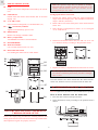
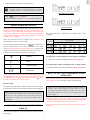
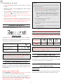
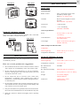
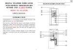
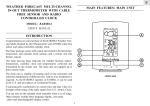
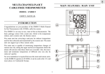
GB JUMBO RF WALL CLOCK WITH INDOOR - OUTDOOR THERMOMETER MODEL NO.: JMR828A Instruction Manual INTRODUCTION A6 Congratulations on purchasing the Jumbo RF Wall Clock with Indoor-Outdoor Thermometer (JMR828A). The JMR828A is a multifunctional radio frequency (RF) controlled clock. It is designed to automatically synchronize its current time and date when brought within range of the radio signal generated from the U.S Atomic clock. A1 A2 Also, this unit displays outdoor and indoor temperature. Included in this package is a remote thermo-sensor. Place the thermo-sensor in a sheltered outdoor location within a 100 feet (30 meters) radius of the main unit and it will transmit outdoor temperature readings to the JMR828A. A3 DESCRIPTION OF PARTS A A1 MAIN UNIT Extra-large liquid crystal display (LCD) • Displays the time, date and day-of-the-week A2 A5 A4 A7 A15 ] Low- battery indicator (remote sensor) A8 A12 A11 Activates when the remote-sensor battery power is low A9 A10 A13 A14 [ ] Radio-reception signal Indicates the condition of radio reception A3 [ ] Low-battery indicator Activates when the battery power is low A4 A5 [ Bottom line of LCD Displays indoor temperature /date / outdoor temperature A6 [ CHANNEL ] Toggles between different channels A7 A11 [°C/°F] Slide Switch [ CLOCK ] button Toggles between Degree Celsius (°C) or Degree Fahrenheit (°F) temperature display unit Toggles between “seconds” and day-of-the-week displays or activates the calendar-clock setting mode A8 [ A12 [ RESET ] Button ] UP button Resets the unit by returning all settings to their default values Increases the value of a setting A9 [ ZONE ] button A13 Battery Compartment Toggles among the 4 US time-zones: Pacific (P), Mountains (M), Central (C) or Eastern (E) Accommodates two UM-3 or AA-size 1.5V batteries A14 Table Stand A10 [ THERMO ] button For placing the unit on a flat surface Retrieves temperature information A15 Wall-Mount Hole For mounting the unit on a wall 1 GB B REMOTE THERMO SENSOR B1 LCD Note: The effective range may be limited by building materials and the position of either the main unit or the remote thermo-sensor unit. Try various set-up arrangements for best result. Displays the current temperature monitored by the remote unit B2 B3 LED indicator Setting up the thermo-sensor unit: Flashes when the remote unit transmits data to the main display unit 1. Position the remote sensor within the signal transmission range of the main display unit. The maximum transmission range is 100 feet (30 metres). °C/°F slide switch 2. Remove the screws of the battery door on the remote thermosensor unit. Selects between Centigrade (°C) and Fahrenheit (°F) B4 [ ] Low-battery indicator 3. Select display of temperature in either °C or °F using the °C/°F slide switch. Appears when the battery power is low B5 RESET button ˚C Returns all settings to default values B6 CHANNEL Accommodates two UM-3 or AA size batteries B7 BATTERY DOOR B8 Wall-mount holder ˚F 1 2 3 RESET Battery compartment 4. Install into the thermo-sensor unit, two UM-3 or "AA" size 1.5V batteries strictly according to the polarities shown. Use to mount remote sensor on a wall B9 Removable table-stand For standing the remote unit on a flat surface B4 2 B1 B3 B2 B5 5. Replace the battery compartment door and secure its screws. B6 Note: Though the sensor is splash proof and is meant for use outside, it should be placed away from direct sunlight, rain, or snow. Once the batteries have been inserted into the remote thermosensor unit, batteries can now be inserted into the main unit. B7 BATTERY INSTALLATION : MAIN UNIT This unit requires two (2) UM-3 or “AA” size batteries for operation. B8 How to insert batteries into the main unit: B9 1. Press the door tab and click-open the door. 2. Insert the batteries strictly according to the polarities shown therein. BATTERY INSTALLATION AND REMOTE THERMO-SENSOR SETUP Follow this step-by-step procedure for installing batteries and setting up the remote-sensor unit. Successful setup should ensure that temperature signals are properly received. UM3 AA 2 UM3 AA GB 3. Replace the door so that it clicks into place. Note: If not disposed of properly, batteries can be harmful. Protect the environment by taking exhausted batteries to authorized disposal stations. day-of-the-week display ] Low-battery indicator Note: [ Replace the batteries when the Low-battery indicator lights up. ABOUT RADIO RECEPTION “second” display The JMR828A is a radio frequency (RF) controlled clock. When located within radio signal range from the U.S Atomic Clock , the clock time will automatically synchronize with time-signal transmission. The benefit of a RF controlled clock is that highlyaccurate time is maintained and manual adjustments to the time and date are not required. The day-of-the-week is displayed as an abbreviation in three languages. When the batteries are first installed, the JMR828A will automatically search for a radio signal. Day-of-the-week Language When in search mode, the antenna icon [ ] will blink. This process takes between two (2) and (10) minutes. After initial search and synchronization with the Atomic clock, short periodic reception-signal scans will commence several times a day. Monday Tuesday Wed. Thursday Friday Saturday Sunday English Spanish French The antenna icon indicates the quality of reception. STRONG To change the “seconds” display to the day-of-the-week display: 1. When the “seconds” are displayed, press [CLOCK] once. WEAK To change the day-of-the-week display to the “seconds” display: NO RECEPTION 1. When the day-of-the-week is displayed, press [CLOCK] once. RECEIVING HOW TO SET THE CALENDAR CLOCK MANUALLY To deactivate the auto-reception of the radio signal, press and hold [ZONE] for 2 seconds and the antenna icon will disappear. ] for 2 To enable this auto-reception again, press and hold [ seconds. The antenna icon will re-appear. When the unit is outside of the radio signal generated from the U.S Atomic Clock, the unit may require manual setting. Interference Reception can be affected by a number of factors. For best reception, place the device away from metal objects and electrical appliances. Note: The RF controlled mechanism overrides manual settings unless auto-reception of radio signal is being deactivated. If manual settings are made, the clock will periodically adjust the time to what is indicated by the radio signal. Note: Interference from sources such as TV sets can affect the signal. If, after batteries have been inserted for ten minutes, the radio signal is not received, then set the time manually (see section: How To Set The Calendar Clock Manually). It is highly unlikely you should ever have the desire (or need ) to manually set the clock time, year, month or date of the JMR828A when it is within signal range of the Atomic clock. However, in the event this becomes necessary please review the following. SECONDS AND DAY-OF-THE-WEEK DISPLAY The “second” and the day-of-the-week share the same section of the display. 3 GB To manually set the clock: Note: 1. Press [CLOCK] and hold for two seconds. The hour will start to flash. Reasons for not receiving a signal from the remote thermo sensor may include: 2. Enter the correct hour using the [ increase the value. 1. The batteries of the remote sensor, the main unit, or both may be low. Low-battery icons should indicate that battery power is low and the batteries require changing. ] button. Hold to rapidly 3. Press [CLOCK] to confirm and proceed to set the minute. Again, use the [ ] button to select the correct minute. • When the temperature falls below freezing point, the batteries will freeze. Frozen batteries will have a lower voltage and result in a lower transmission radius. 4. Press [CLOCK] to proceed to set the year, month, day and language for day - of - week. 5. When finished, press [CLOCK]. The time and date are now set. 2. The transmission range is too far. 6. To select the U.S. time - zone, press [ZONE] to toggle among Pacific(P), Mountains (M), Central(C) or Eastern (E). • Shorten the distance. 3. The transmission path is cluttered with obstacles and interference. TEMPERATURE DISPLAY • Shorten the distance or reposition the remote sensor or the main unit. This unit displays temperature in °C or °F TEMPERATURE TREND INDICATORS The temperature-trend indicator show the trends of the collected remote temperature readings for the past half hour. Arrows indicate a rising, steady or falling trend. temperature display The remote outdoor temperature display has a kinetic-wave display. The kinetic-wave display shows the signal-receiving status by the main unit. The are three possible forms. Arrow indicator TEMP Temperature Trend The unit is in searching mode. Temperature readings are securely registered. Rising TEMP Steady TEMP Falling Note : If the reading goes above or below the measuring range of the remote unit (stated in specification), the display will show "HHH" or "LLL". No signals HOW TO RESET THE UNIT NOTE: JMR828A can also scan for max 3 different remote temperature channels. To do so, simply press the CHANNEL button once to switch to the different channel. Press [RESET] to return all settings to the factory values. The button is used when the unit is not operating in a favorable way, such as in the rare case of a malfunction. SENSOR TRANSMISSION STATUS HOW TO WALL MOUNT OR USE TABLE STAND If blanks "----" appear on the remote temperature display of the main, then the unit is not receiving a signal from the remote thermo sensor. The user may be able to receive a signal by doing a signal search. MAIN UNIT Remote Sensor Signal Search: Flip the table stand open to place the unit on a steady, flat surface. Or use the recessed hole on the back to mount it on a wall. Press [THERMO] and [CHANNEL] together for 2 seconds. The unit will search for a remote thermo-sensor signal. If the unit still cannot receive a signal, check the batteries to ensure they are properly installed and have ample power. Try repositioning the units as they might be having a temperature transmission block due to signal interference. 4 GB Wall-mount Table Stand SPECIFICATIONS MAIN UNIT Clock Functions : Auto synchronizes current time and date by Radio signal from the U.S. Atomic Clock Calendar : Day of week in English / French / Spanish Current month / day format Clock Time : 12-hour format Accuracy : +/- 0.5 second/day (when RF is disabled) General specification REMOTE THERMO SENSOR This sensor comes with a wall-mount holder and a removable stand. Use either to hold the unit in place. Wall-mount Radio Control Table Stand Power : Two (2) UM-3 or “AA” size 1.5V battery Unit Dimension : 10.51x8.03x1.42 inches (267x204x36mm) Unit Weight : approx. 23.28 ounces (660 gms.) (without batteries) 2 Indoor Temperature Measurement Temperature Measuring Range : 23°F to 122°F (-5°C to 50 °C) Temperature Resolution : 32.2 °F(0.1 °C) MAINTENANCE REMOTE THERMO SENSOR When handled properly, this unit is engineered to give you years of satisfactory service. Here are several product-care suggestions: 1. Do not immerse the unit in water. If the unit comes in contact with a liquid, dry it immediately with a soft lint-free cloth. Remote Temperature Measuring Range : -4°F to 140°F (-20°C to 60 °C) Temperature resolution : 32.2 °F(0.1 °C) RF Transmission Frequency : 433 MHz RF Transmission Range : Maximum 100 feet (30 meters) 2. Do not clean the unit with abrasive or corrosive materials. Abrasive cleaning agents may scratch the plastic parts and corrode the electronic circuit. 3. Do not subject the unit to excessive force, shock, dust, temperature, or humidity. Such treatment may result in malfunction, a shorter electronic life span, damaged batteries, or distorted parts. 4. Do not tamper with the unit’s internal components. Doing so will terminate the unit’s warranty and may cause damage. The unit contains no user-serviceable parts. 5. Only use new batteries as specified in this instruction manual. Do not mix new and old batteries as the old batteries may leak. 6. Read this instruction manual thoroughly before operating the unit. 5 Power : Two (2) UM-3 or “AA” 1.5V battery Weight : 3.53 ounces (100gms) (without batteries) Dimension : 3.62x2.36x.83 inches (92x60x21mm) GB NOTE ON COMPLIANCE CUSTOMER ASSISTANCE Warning: Changes or modifications to this unit not expressly approved by the party responsible for compliance could void the user's authority to operate the equipment. Should you require assistance regarding this product and its FCC : 800-853-8883 or via email at [email protected]. Our customer care department is available 24-7-365. operation, please contact our customer care department at NOTE: This equipment has been tested and found to comply with the limits for a Class B digital device, pursuant to Part 15 of the FCC Rules. These limits are designed to provide reasonable protection against harmful interference in a residential installation. This equipment generates, uses and can radiate radio frequency energy and, if not installed and used in accordance with the instructions, may cause harmful interference to radio communications. WARRANTY This product is warranted to be free of manufacturing defects for a period of 3 months from date of retail purchase. Defective product should be directed to the place of retail purchase for exchange. However, there is no guarantee that interference will not occur in a particular installation. If this equipment does cause harmful interference to radio or television reception, which can be determined by turning the equipment off and on, the user is encouraged to try to correct the interference by one or more of the following measures: Should this not be possible, contact our customer care department for assistance and a return material authorization. No returns may be made without a return authorization. Please retain your retail receipt as you may be asked to provide a copy of it for proof of date purchased. o Reorient or relocate the receiving antenna. This warranty does not cover product subjected to abuse, misuse, accidental damage or tampering. o Increase the separation between the equipment and receiver. Upon return of the defective product, Oregon Scientific will at its discretion, replace the product with either a new or a tested reconditioned product. Should the product be out of warranty, the consumer may purchase directly from Oregon Scientific a replacement at reasonable cost plus shipping and handling. o Connect the equipment into an outlet on a circuit different from that to which the receiver is needed. o Consult the dealer of an experienced radio/TV technician for help. Company Name: Oregon Scientific, Inc. Address: 19861 SW 95th Place, Tualatin, Oregon 97062, USA Website address: www.oregonscientific.com. Name and model number of the product: Jumbo RF wall Clock with indoor - outdoor Thermometer JMR828A CAUTION — The content of this manual is subject to change without further notice. — Due to printing limitation, the displays shown in this manual may differ from the actual display. — The contents of this manual may not be reproduced without the permission of the manufacturer. 6 7 GB GB MODEL: JMR828A JUMBO RF WALL CLOCK WITH INDOOR-OUTDOOR THERMOMETER Instruction Manual **** Mode D'emploi **** Bedienungsanleitung **** Manuale di Istruzioni **** Instrucciones de Funcionamiento 8